EP4215307A1 - Welding apparatus for button-type secondary battery - Google Patents
Welding apparatus for button-type secondary battery Download PDFInfo
- Publication number
- EP4215307A1 EP4215307A1 EP21892211.0A EP21892211A EP4215307A1 EP 4215307 A1 EP4215307 A1 EP 4215307A1 EP 21892211 A EP21892211 A EP 21892211A EP 4215307 A1 EP4215307 A1 EP 4215307A1
- Authority
- EP
- European Patent Office
- Prior art keywords
- probes
- welding
- base
- jig
- electrode tab
- Prior art date
- Legal status (The legal status is an assumption and is not a legal conclusion. Google has not performed a legal analysis and makes no representation as to the accuracy of the status listed.)
- Pending
Links
Images




Classifications
-
- B—PERFORMING OPERATIONS; TRANSPORTING
- B23—MACHINE TOOLS; METAL-WORKING NOT OTHERWISE PROVIDED FOR
- B23K—SOLDERING OR UNSOLDERING; WELDING; CLADDING OR PLATING BY SOLDERING OR WELDING; CUTTING BY APPLYING HEAT LOCALLY, e.g. FLAME CUTTING; WORKING BY LASER BEAM
- B23K26/00—Working by laser beam, e.g. welding, cutting or boring
- B23K26/02—Positioning or observing the workpiece, e.g. with respect to the point of impact; Aligning, aiming or focusing the laser beam
- B23K26/03—Observing, e.g. monitoring, the workpiece
-
- B—PERFORMING OPERATIONS; TRANSPORTING
- B23—MACHINE TOOLS; METAL-WORKING NOT OTHERWISE PROVIDED FOR
- B23K—SOLDERING OR UNSOLDERING; WELDING; CLADDING OR PLATING BY SOLDERING OR WELDING; CUTTING BY APPLYING HEAT LOCALLY, e.g. FLAME CUTTING; WORKING BY LASER BEAM
- B23K26/00—Working by laser beam, e.g. welding, cutting or boring
- B23K26/20—Bonding
- B23K26/21—Bonding by welding
-
- B—PERFORMING OPERATIONS; TRANSPORTING
- B23—MACHINE TOOLS; METAL-WORKING NOT OTHERWISE PROVIDED FOR
- B23K—SOLDERING OR UNSOLDERING; WELDING; CLADDING OR PLATING BY SOLDERING OR WELDING; CUTTING BY APPLYING HEAT LOCALLY, e.g. FLAME CUTTING; WORKING BY LASER BEAM
- B23K26/00—Working by laser beam, e.g. welding, cutting or boring
- B23K26/20—Bonding
- B23K26/21—Bonding by welding
- B23K26/22—Spot welding
-
- B—PERFORMING OPERATIONS; TRANSPORTING
- B23—MACHINE TOOLS; METAL-WORKING NOT OTHERWISE PROVIDED FOR
- B23K—SOLDERING OR UNSOLDERING; WELDING; CLADDING OR PLATING BY SOLDERING OR WELDING; CUTTING BY APPLYING HEAT LOCALLY, e.g. FLAME CUTTING; WORKING BY LASER BEAM
- B23K26/00—Working by laser beam, e.g. welding, cutting or boring
- B23K26/02—Positioning or observing the workpiece, e.g. with respect to the point of impact; Aligning, aiming or focusing the laser beam
- B23K26/04—Automatically aligning, aiming or focusing the laser beam, e.g. using the back-scattered light
-
- B—PERFORMING OPERATIONS; TRANSPORTING
- B23—MACHINE TOOLS; METAL-WORKING NOT OTHERWISE PROVIDED FOR
- B23K—SOLDERING OR UNSOLDERING; WELDING; CLADDING OR PLATING BY SOLDERING OR WELDING; CUTTING BY APPLYING HEAT LOCALLY, e.g. FLAME CUTTING; WORKING BY LASER BEAM
- B23K31/00—Processes relevant to this subclass, specially adapted for particular articles or purposes, but not covered by any single one of main groups B23K1/00 - B23K28/00
- B23K31/12—Processes relevant to this subclass, specially adapted for particular articles or purposes, but not covered by any single one of main groups B23K1/00 - B23K28/00 relating to investigating the properties, e.g. the weldability, of materials
- B23K31/125—Weld quality monitoring
-
- B—PERFORMING OPERATIONS; TRANSPORTING
- B23—MACHINE TOOLS; METAL-WORKING NOT OTHERWISE PROVIDED FOR
- B23K—SOLDERING OR UNSOLDERING; WELDING; CLADDING OR PLATING BY SOLDERING OR WELDING; CUTTING BY APPLYING HEAT LOCALLY, e.g. FLAME CUTTING; WORKING BY LASER BEAM
- B23K37/00—Auxiliary devices or processes, not specially adapted for a procedure covered by only one of the other main groups of this subclass
- B23K37/04—Auxiliary devices or processes, not specially adapted for a procedure covered by only one of the other main groups of this subclass for holding or positioning work
- B23K37/0426—Fixtures for other work
- B23K37/0435—Clamps
- B23K37/0443—Jigs
-
- G—PHYSICS
- G01—MEASURING; TESTING
- G01N—INVESTIGATING OR ANALYSING MATERIALS BY DETERMINING THEIR CHEMICAL OR PHYSICAL PROPERTIES
- G01N27/00—Investigating or analysing materials by the use of electric, electrochemical, or magnetic means
- G01N27/02—Investigating or analysing materials by the use of electric, electrochemical, or magnetic means by investigating impedance
- G01N27/04—Investigating or analysing materials by the use of electric, electrochemical, or magnetic means by investigating impedance by investigating resistance
- G01N27/20—Investigating the presence of flaws
-
- H—ELECTRICITY
- H01—ELECTRIC ELEMENTS
- H01M—PROCESSES OR MEANS, e.g. BATTERIES, FOR THE DIRECT CONVERSION OF CHEMICAL ENERGY INTO ELECTRICAL ENERGY
- H01M10/00—Secondary cells; Manufacture thereof
- H01M10/04—Construction or manufacture in general
- H01M10/0404—Machines for assembling batteries
-
- H—ELECTRICITY
- H01—ELECTRIC ELEMENTS
- H01M—PROCESSES OR MEANS, e.g. BATTERIES, FOR THE DIRECT CONVERSION OF CHEMICAL ENERGY INTO ELECTRICAL ENERGY
- H01M10/00—Secondary cells; Manufacture thereof
- H01M10/04—Construction or manufacture in general
- H01M10/0422—Cells or battery with cylindrical casing
- H01M10/0427—Button cells
-
- H—ELECTRICITY
- H01—ELECTRIC ELEMENTS
- H01M—PROCESSES OR MEANS, e.g. BATTERIES, FOR THE DIRECT CONVERSION OF CHEMICAL ENERGY INTO ELECTRICAL ENERGY
- H01M50/00—Constructional details or processes of manufacture of the non-active parts of electrochemical cells other than fuel cells, e.g. hybrid cells
- H01M50/10—Primary casings; Jackets or wrappings
- H01M50/102—Primary casings; Jackets or wrappings characterised by their shape or physical structure
- H01M50/109—Primary casings; Jackets or wrappings characterised by their shape or physical structure of button or coin shape
-
- H—ELECTRICITY
- H01—ELECTRIC ELEMENTS
- H01M—PROCESSES OR MEANS, e.g. BATTERIES, FOR THE DIRECT CONVERSION OF CHEMICAL ENERGY INTO ELECTRICAL ENERGY
- H01M50/00—Constructional details or processes of manufacture of the non-active parts of electrochemical cells other than fuel cells, e.g. hybrid cells
- H01M50/10—Primary casings; Jackets or wrappings
- H01M50/147—Lids or covers
- H01M50/148—Lids or covers characterised by their shape
- H01M50/153—Lids or covers characterised by their shape for button or coin cells
-
- H—ELECTRICITY
- H01—ELECTRIC ELEMENTS
- H01M—PROCESSES OR MEANS, e.g. BATTERIES, FOR THE DIRECT CONVERSION OF CHEMICAL ENERGY INTO ELECTRICAL ENERGY
- H01M50/00—Constructional details or processes of manufacture of the non-active parts of electrochemical cells other than fuel cells, e.g. hybrid cells
- H01M50/50—Current conducting connections for cells or batteries
- H01M50/528—Fixed electrical connections, i.e. not intended for disconnection
-
- H—ELECTRICITY
- H01—ELECTRIC ELEMENTS
- H01M—PROCESSES OR MEANS, e.g. BATTERIES, FOR THE DIRECT CONVERSION OF CHEMICAL ENERGY INTO ELECTRICAL ENERGY
- H01M50/00—Constructional details or processes of manufacture of the non-active parts of electrochemical cells other than fuel cells, e.g. hybrid cells
- H01M50/50—Current conducting connections for cells or batteries
- H01M50/531—Electrode connections inside a battery casing
-
- B—PERFORMING OPERATIONS; TRANSPORTING
- B23—MACHINE TOOLS; METAL-WORKING NOT OTHERWISE PROVIDED FOR
- B23K—SOLDERING OR UNSOLDERING; WELDING; CLADDING OR PLATING BY SOLDERING OR WELDING; CUTTING BY APPLYING HEAT LOCALLY, e.g. FLAME CUTTING; WORKING BY LASER BEAM
- B23K2101/00—Articles made by soldering, welding or cutting
- B23K2101/36—Electric or electronic devices
-
- B—PERFORMING OPERATIONS; TRANSPORTING
- B23—MACHINE TOOLS; METAL-WORKING NOT OTHERWISE PROVIDED FOR
- B23K—SOLDERING OR UNSOLDERING; WELDING; CLADDING OR PLATING BY SOLDERING OR WELDING; CUTTING BY APPLYING HEAT LOCALLY, e.g. FLAME CUTTING; WORKING BY LASER BEAM
- B23K2101/00—Articles made by soldering, welding or cutting
- B23K2101/36—Electric or electronic devices
- B23K2101/38—Conductors
-
- Y—GENERAL TAGGING OF NEW TECHNOLOGICAL DEVELOPMENTS; GENERAL TAGGING OF CROSS-SECTIONAL TECHNOLOGIES SPANNING OVER SEVERAL SECTIONS OF THE IPC; TECHNICAL SUBJECTS COVERED BY FORMER USPC CROSS-REFERENCE ART COLLECTIONS [XRACs] AND DIGESTS
- Y02—TECHNOLOGIES OR APPLICATIONS FOR MITIGATION OR ADAPTATION AGAINST CLIMATE CHANGE
- Y02E—REDUCTION OF GREENHOUSE GAS [GHG] EMISSIONS, RELATED TO ENERGY GENERATION, TRANSMISSION OR DISTRIBUTION
- Y02E60/00—Enabling technologies; Technologies with a potential or indirect contribution to GHG emissions mitigation
- Y02E60/10—Energy storage using batteries
-
- Y—GENERAL TAGGING OF NEW TECHNOLOGICAL DEVELOPMENTS; GENERAL TAGGING OF CROSS-SECTIONAL TECHNOLOGIES SPANNING OVER SEVERAL SECTIONS OF THE IPC; TECHNICAL SUBJECTS COVERED BY FORMER USPC CROSS-REFERENCE ART COLLECTIONS [XRACs] AND DIGESTS
- Y02—TECHNOLOGIES OR APPLICATIONS FOR MITIGATION OR ADAPTATION AGAINST CLIMATE CHANGE
- Y02P—CLIMATE CHANGE MITIGATION TECHNOLOGIES IN THE PRODUCTION OR PROCESSING OF GOODS
- Y02P70/00—Climate change mitigation technologies in the production process for final industrial or consumer products
- Y02P70/50—Manufacturing or production processes characterised by the final manufactured product
Definitions
- the present invention relates to a welding device for a button-type secondary battery, and more particularly, to a welding device which is capable of welding an electrode tab of an electrode assembly to an electrode tab by using a laser, wherein, after performing the welding by measuring a resistance value at a welding point, whether welding defects occur is quickly checked.
- a button-type battery commonly used as a coin-type battery or a button-type battery has a thin button shape and is widely used in various devices such as remote controllers, clocks, toys, computer parts, and the like.
- Such a button-type battery is mainly manufactured as a non-rechargeable primary battery, but is also widely manufactured as a secondary battery that is chargeable and dischargeable as miniaturized devices are developed.
- the button-type secondary battery also has a structure in which an electrode assembly and an electrolyte are embedded in a case to repeatedly perform charging and discharging, like the button-type secondary battery or the cylindrical or pouch-type secondary battery.
- the button-type secondary battery has a different property in that a structure is more simple, and a can has a low height, but is structurally similar in that a jelly roll-type electrode assembly is mounted inside the can.
- the button-type secondary battery is manufactured in the form in which the electrode assembly is embedded in the can formed by coupling an upper can to a lower can.
- the electrode assembly is manufactured by winding a separator, a negative electrode, a separator, and a positive electrode, which are in a stacked state, around a core.
- the electrode assembly has a structure a center hole is formed at a center after the core is removed and is manufactured so that electrode tabs (a negative electrode tab and a positive electrode tab) protrude upward and downward, respectively.
- electrode tabs a negative electrode tab and a positive electrode tab
- the electrode tab disposed at an upper side is the positive electrode tab
- the electrode tab disposed at a lower side is the negative electrode tab. That is, when the electrode assembly is embedded, the upper can and the lower can are coupled and sealed so that the upper can and the lower can are electrically insulated from each other.
- the upper can is connected to the positive electrode tab to form a positive electrode
- the lower can is connected to the negative electrode tab to form a negative electrode.
- FIG. 1a which illustrates a state in which the electrode tab is welded to the upper can in a process of assembling the button-type secondary battery according to the related art
- a state in which an electrode assembly 3 is mounted in a lower can 2 so that a negative electrode tab 3b of electrode tabs 3a and 3b according to the related art is disposed in a center hole laser is irradiated to weld the negative electrode tab 3b on a bottom surface inside the lower can 2, and the positive electrode 3a is withdrawn to the outside and then is welded to an inner surface of the can 1 that is an upper can.
- the can 1 is press-fitted into an upper portion of the lower can 2 and then coupled.
- a resistance value between the electrode tab 3a and the can 1 varies in magnitude according to a length of a bead generated at the welded portion during the welding.
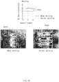
- FIG. 1b which illustrates a shape of the bead during weak welding and a shape of the bead during normal welding and a graph showing a difference in internal resistance during the weak welding and the normal welding
- a contact area between the electrode tab 3a and the can 1 increases, and thus, DC resistance that is internal resistance between the electrode tab 3a and the can 1 relatively decrease.
- the contact area between the electrode tab 3a and the can 1 is reduced, and thus, the magnitude of the DC resistance relatively increases.
- a main object of the present invention is to provide a welding device for a button-type secondary battery, which is capable of determining whether welding defects occur immediately after welding is performed using a phenomenon, in which a magnitude of an internal resistance varies according to welding quality as described above.
- the present invention for achieving the above object provides a welding device for a button-type, which welds an electrode tab protruding from an electrode assembly to a can in which the electrode assembly is mounted, the welding device including: a base configured to support a bottom surface of the can when an inner surface of the can faces an upper side, and the electrode tab is in contact with the inner surface of the can; a jig disposed on the base to fix the electrode tab on the base and having an opening hole through which laser for welding the electrode tab to the can passes; a laser irradiation device configured to irradiate the laser to the opening hole when the jig fixes the electrode tab to the can; and four probes mounted on the base or the jig, wherein two probes of the probes are connected to a power source so that current flows to welding portions of the can and the electrode tab when the probes are in contact with the welding portions, and remaining two probes are connected to a voltmeter to measure voltages at the welding portions to be in contact with the welding portions.
- the electrode tab is a positive electrode tab, and the can is an upper can.
- the electrode tab may be a negative electrode tab, and the can may be a lower can.
- Two probes of the four probes may be installed on the jig, and two probes of the four probes may be installed on the base.
- a gap between the two probes through which the current flows may be greater than that between the two probes connected to the voltmeter.
- the two probes through which the current flows may be mounted on the jig, and the two probes connected to the voltmeter may be mounted on the base, or the two probes through which the current flows may be mounted on the base, and the two probes connected to the voltmeter may be mounted on the jig.
- the probes may be disposed to be spaced a predetermined distance from a point at which the laser is irradiated.
- the jig may be capable of ascending and descending to approach the base when descends and to be away from the base when ascends.
- Each of the probes may be provided as a pogo pin that overcomes elastic force of a spring therein and is pressed.
- the welding device may further include a controller that calculates resistance of each of the welding portions by calculating the current supplied from the power source and the voltage measured by the voltmeter, and compares the calculated resistance with input data to determine whether welding defects occur.
- the probes When the probes are mounted on the base or the jig, the probes may be mounted to be electrically insulated from the base and the jig.
- the probes may be disposed to be spaced a predetermined distance from a point at which the laser is irradiated to prevent the heat damage by the laser from occurring.
- the jig may be configured to ascend and descend so as to approach the base when descends and to be away from the base when ascends, thereby measuring the resistance of the secondary batteries having various sizes.
- the probe may be provided as the pogo pin that overcomes the internal elastic force of the spring and is pressed, so that the probe is in contact with the surfaces of the electrode tab and the can at the appropriate pressure without leaving the scratch on the surfaces.
- the controller that determines whether the welding defects occur by comparing the calculated resistance with the data that is input in advance may be further provided to more quickly determine whether the welding defects occur.
- the present invention relates to a welding device for a button-type secondary battery, which is capable of determining whether defects in welding quality occur by applying power between an electrode tab (positive electrode tab) and a can (upper can) to calculate internal resistance and comparing numerical values of the internal resistance after the welding is performed using a phenomenon in which magnitude of the internal resistance varies according to the welding quality.
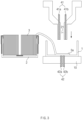
- FIG. 2 is a simplified view illustrating a welding device for a button-type secondary battery according to the present invention
- FIG. 3 is a view illustrating a state before a can and an electrode tab are seated on the welding device illustrated in FIG. 2
- a jig descends
- FIG. 4 is a view illustrating a state in which the jig descends, and laser is irradiated in the state of FIG. 2 .
- a welding device for a button-type secondary battery provided in this embodiment is provided to weld an electrode tab 3a protruding from an electrode assembly to a can 1 in which the electrode assembly 3 is mounted, and includes a base 10, a jig 20, a laser irradiation device 30, and four probes 40 (41 and 42).
- the electrode tab 3a is a positive electrode tab
- the can 1 is an upper can.
- the electrode tab may be a negative electrode tab
- the can may be a lower can according to a welding position.
- the base 10 is provided in a flat plate shape having a predetermined thickness to support a bottom surface of the can 1 when the electrode tab 3a is in contact with an inner surface of the can 1 and also has a structure in which a plurality of holes are punched vertically so that the probes 42 (42a and 42b) are inserted.
- the jig 20 is disposed on the base 10 to press the electrode tab 3a disposed on the base 10 with a load, and an opening hole 21 is formed so that the laser for welding the electrode tab 3a to the can 1 passes therethrough.
- a size and shape of the jig 20 are not limited, a lower end seated on the electrode tab 3a has a size that is enough to be seated on the electrode tab 3a and has a sufficient thickness to prevent thermal damage during the laser irradiation. Also, it has a structure in which the plurality of holes are punched so that the probes 41 (41a and 41b) are inserted.
- the laser irradiation device 30 irradiates the laser in a state in which an output and an irradiation path are controlled so that a welding bead is formed with a predetermined width and length.
- the two probes 41 (41a and 41b) of the probes 40 are connected to a power source 50 to be in contact with welding portions of the can 1 and the electrode tab 3a so that current flows to the welding portions, and the remaining two probes 42 (42a and 42b) are connected to a voltmeter 60 to measure voltages at the welding portions to be in contact with the welding portions.
- resistance at the welding point may be calculated by Ohm's law.
- FIG. 6 which illustrates a change in DC resistance and separation strength according to a length of the bead
- the output of the laser irradiated from the laser irradiation device 30 and the resistance value to a movement distance are higher than reference values, it may be determined as defective welding, and if the resistance value is within a predetermined reference value range, it may be determined as normal welding.
- the welding device for the button-type secondary battery may include a controller 70 that calculates the resistance of the welding portion by calculating the current supplied from the power source 50 and the voltage measured by the voltmeter 60, and compares the calculated resistance with input data to determine whether the welding defects occur.
- the two probes of the four probes 40 in this embodiment are installed on the jig 20, and the two probes are installed on the base 10 so that the resistance is measured at four points.
- a gap d1 between the two probes 41a and 41b through which the current flows is provided to be wider than a gap d2 between the two probes 42a and 42b connected to the voltmeter 60.
- the distance between the probes 41a, 41b, 42a, 42b are constantly maintained in the vertical direction (i.e., it is preferable that all of a gap between the probes 41a and 42a, a gap between the probes 42a and 42b, and a gap between probes 42b and 41b among the probes are constant).
- a voltage may be measured through the probes 42a and 42b mounted on the lower base 10.
- the resistance at the points (the welded points) that are in contact with the probes 40 may be calculated.
- the two probes 41a and 41b through which the current flows are mounted on the jig 20, and the two probes 42a and 42b connected to the voltmeter 60 are mounted on the base 10.
- the two probes 41a and 41b through which the current flows are mounted on the base 10, and the two probes 42a and 42b connected to the voltmeter 60 may be mounted on the jig 20.
- the probes 42a and 42b mounted on the base 10 are disposed to be spaced a predetermined distance from the point at which the laser is irradiated to prevent thermal damage from occurring by the welding. That is, the laser welding point is preferably determined between the probes 42a and 42b mounted on the base 10.
- the jig 20 may be configured to ascend and descend so as to approach the base 10 when descends and to be away from the base 10 when ascends.
- the probes 40 are mounted on the base 10 or the jig 20, it is preferable that the probes 40 are mounted to be electrically insulated from the base 10 or the jig 20 (for example, the probes are mounted in a state of being coupled to an insulating gasket on an outer surface that is in contact with the jig or the base or in a state of being coated with an insulating layer).
- Embodiment 2 a probe provided as a pogo pin is provided as Embodiment 2.
- a probe which is commonly called a pogo pin, is a probe that is provided with a spring mounted therein and is contactable with an elastic force applied therein.
- the probe is mainly used when examining an electronic circuit or a semiconductor chip.
- each of the probes 40 (41 and 42) provided in this embodiment includes a body 45 in a hollow pipe shape, a spring 44 inserted into the body 45, a first probe pin 43 having a portion inserted into one side of the body 45 and having an end fixed to one end of the spring 44, and a second probe pin 46 configured to support the other end of the spring 44 and having a portion inserted into the other side of the body 45.
- the first probe pin 43 and the second probe pin 46 are prevented from being separated from the body 45 and are coupled to press the spring 40 so that the spring is pressed by a predetermined distance (inserted into the body).
- any one of the first probe pin 43 and the second probe pin 46 is electrically connected to a power source 50 or a voltmeter 60 for applying current, and the other is disposed to be in contact with an electrode tab 3a or a can 1.
- the jig 20 when the jig 20 is disposed on the electrode tab 3a and the can 1 in a state in which the electrode tab 3a and the can 1 are seated on the base 10, in the probes 41 and 42 having the above-described pogo pin structure, since the probe pins 43 and 46 are retracted by the pressing of the spring 44, the stable contact of the electrode tab 3a and the can 1 while maintaining the electrical connection may be secured.
- the spring 44 is made of a metal having electrical conductivity so that the first probe pin 43 and the second probe pin 46 are electrically connected, and an insulating layer may be applied to an outer surface of the body 45 so as to be insulated from the base 10 and the jig 20.
- the welding device for the button-type secondary battery of the present invention having the technical properties as described above may determine immediately whether welding defects occur after the welding is performed by measuring resistance between the electrode tab 3a and the can 1.
- the probes 40 may be disposed to be spaced a predetermined distance from a point at which laser is irradiated, thereby preventing thermal damage from occurring by the laser.
- the jig 20 may be configured to ascend and descend so as to approach the base 10 when descends and to be away from the base 10 when ascends, thereby measuring the resistance of the secondary batteries having various sizes.
- the probe 40 may be provided as a pogo pin that overcomes internal elastic force of the spring and is pressed, so that the probe is in contact with the surfaces of the electrode tab 3a and the can 1 at the appropriate pressure without leaving scratch on the surfaces.
- a controller 70 that determines whether the welding defects occur by comparing the calculated resistance with the data that is input in advance may be further provided to more quickly determine whether the welding defects occur.
- the probes 40 may be mounted to be electrically insulated from the base 10 or the jig 20, thereby preventing the measured values from being changed by the external factors.
Landscapes
- Engineering & Computer Science (AREA)
- Physics & Mathematics (AREA)
- Optics & Photonics (AREA)
- Chemical & Material Sciences (AREA)
- Chemical Kinetics & Catalysis (AREA)
- Electrochemistry (AREA)
- General Chemical & Material Sciences (AREA)
- Mechanical Engineering (AREA)
- Plasma & Fusion (AREA)
- Manufacturing & Machinery (AREA)
- Quality & Reliability (AREA)
- Life Sciences & Earth Sciences (AREA)
- Pathology (AREA)
- Immunology (AREA)
- General Physics & Mathematics (AREA)
- General Health & Medical Sciences (AREA)
- Biochemistry (AREA)
- Analytical Chemistry (AREA)
- Health & Medical Sciences (AREA)
- Connection Of Batteries Or Terminals (AREA)
- Laser Beam Processing (AREA)
Abstract
Description
- The present application claims the benefit of the priority of
Korean Patent Application No. 10-2020-0149609, filed on November 10, 2020 - The present invention relates to a welding device for a button-type secondary battery, and more particularly, to a welding device which is capable of welding an electrode tab of an electrode assembly to an electrode tab by using a laser, wherein, after performing the welding by measuring a resistance value at a welding point, whether welding defects occur is quickly checked.
- A button-type battery commonly used as a coin-type battery or a button-type battery has a thin button shape and is widely used in various devices such as remote controllers, clocks, toys, computer parts, and the like.
- Such a button-type battery is mainly manufactured as a non-rechargeable primary battery, but is also widely manufactured as a secondary battery that is chargeable and dischargeable as miniaturized devices are developed.
- Also, the button-type secondary battery also has a structure in which an electrode assembly and an electrolyte are embedded in a case to repeatedly perform charging and discharging, like the button-type secondary battery or the cylindrical or pouch-type secondary battery.
- Particularly, the button-type secondary battery has a different property in that a structure is more simple, and a can has a low height, but is structurally similar in that a jelly roll-type electrode assembly is mounted inside the can.
- The button-type secondary battery is manufactured in the form in which the electrode assembly is embedded in the can formed by coupling an upper can to a lower can.
- The electrode assembly is manufactured by winding a separator, a negative electrode, a separator, and a positive electrode, which are in a stacked state, around a core. Thus, the electrode assembly has a structure a center hole is formed at a center after the core is removed and is manufactured so that electrode tabs (a negative electrode tab and a positive electrode tab) protrude upward and downward, respectively. Typically, when the electrode tab is seated in the lower can, the electrode tab disposed at an upper side is the positive electrode tab, and the electrode tab disposed at a lower side is the negative electrode tab. That is, when the electrode assembly is embedded, the upper can and the lower can are coupled and sealed so that the upper can and the lower can are electrically insulated from each other. Here, the upper can is connected to the positive electrode tab to form a positive electrode, and the lower can is connected to the negative electrode tab to form a negative electrode.
- As illustrated in
FIG. 1a , which illustrates a state in which the electrode tab is welded to the upper can in a process of assembling the button-type secondary battery according to the related art, in a state in which anelectrode assembly 3 is mounted in alower can 2 so that anegative electrode tab 3b ofelectrode tabs negative electrode tab 3b on a bottom surface inside thelower can 2, and thepositive electrode 3a is withdrawn to the outside and then is welded to an inner surface of thecan 1 that is an upper can. After the welding is performed in a state in which thecan 1 is disposed on thebase 6 so that the inner surface thereof faces an upper side, thecan 1 is press-fitted into an upper portion of thelower can 2 and then coupled. - When the welding is performed in the state in which the
positive electrode tab 3a is disposed on the inner surface of thecan 1, in a state in which ajig 7 having a pipe shape presses and fix the positive electrode tab, if the laser is irradiated from alaser irradiation device 5 through a hole of thejig 7, thepositive electrode tab 3a is melted and welded to thecan 1. - A resistance value between the
electrode tab 3a and thecan 1 varies in magnitude according to a length of a bead generated at the welded portion during the welding. - That is, referring to
FIG. 1b , which illustrates a shape of the bead during weak welding and a shape of the bead during normal welding and a graph showing a difference in internal resistance during the weak welding and the normal welding, when the normal welding is performed to a sufficient length to form a bead having a long length, a contact area between theelectrode tab 3a and thecan 1 increases, and thus, DC resistance that is internal resistance between theelectrode tab 3a and the can 1 relatively decrease. However, when the sufficient bead is not formed, and the weak welding is performed, the contact area between theelectrode tab 3a and thecan 1 is reduced, and thus, the magnitude of the DC resistance relatively increases. - Therefore, a main object of the present invention is to provide a welding device for a button-type secondary battery, which is capable of determining whether welding defects occur immediately after welding is performed using a phenomenon, in which a magnitude of an internal resistance varies according to welding quality as described above.
- The present invention for achieving the above object provides a welding device for a button-type, which welds an electrode tab protruding from an electrode assembly to a can in which the electrode assembly is mounted, the welding device including: a base configured to support a bottom surface of the can when an inner surface of the can faces an upper side, and the electrode tab is in contact with the inner surface of the can; a jig disposed on the base to fix the electrode tab on the base and having an opening hole through which laser for welding the electrode tab to the can passes; a laser irradiation device configured to irradiate the laser to the opening hole when the jig fixes the electrode tab to the can; and four probes mounted on the base or the jig, wherein two probes of the probes are connected to a power source so that current flows to welding portions of the can and the electrode tab when the probes are in contact with the welding portions, and remaining two probes are connected to a voltmeter to measure voltages at the welding portions to be in contact with the welding portions. In the present invention, it has been described that the electrode tab is a positive electrode tab, and the can is an upper can. However, if the jig is insertable into a center hole of the electrode assembly, the electrode tab may be a negative electrode tab, and the can may be a lower can.
- Two probes of the four probes may be installed on the jig, and two probes of the four probes may be installed on the base.
- A gap between the two probes through which the current flows may be greater than that between the two probes connected to the voltmeter.
- Alternatively, the two probes through which the current flows may be mounted on the jig, and the two probes connected to the voltmeter may be mounted on the base, or the two probes through which the current flows may be mounted on the base, and the two probes connected to the voltmeter may be mounted on the jig.
- The probes may be disposed to be spaced a predetermined distance from a point at which the laser is irradiated.
- The jig may be capable of ascending and descending to approach the base when descends and to be away from the base when ascends.
- Each of the probes may be provided as a pogo pin that overcomes elastic force of a spring therein and is pressed.
- The welding device may further include a controller that calculates resistance of each of the welding portions by calculating the current supplied from the power source and the voltage measured by the voltmeter, and compares the calculated resistance with input data to determine whether welding defects occur.
- When the probes are mounted on the base or the jig, the probes may be mounted to be electrically insulated from the base and the jig.
- The welding device for the button-type secondary battery of the present invention having the technical properties as described above may determine immediately whether welding defects occur after the welding is performed by measuring the resistance between the electrode tab and the can.
- The probes may be disposed to be spaced a predetermined distance from a point at which the laser is irradiated to prevent the heat damage by the laser from occurring.
- The jig may be configured to ascend and descend so as to approach the base when descends and to be away from the base when ascends, thereby measuring the resistance of the secondary batteries having various sizes.
- The probe may be provided as the pogo pin that overcomes the internal elastic force of the spring and is pressed, so that the probe is in contact with the surfaces of the electrode tab and the can at the appropriate pressure without leaving the scratch on the surfaces.
- The controller that determines whether the welding defects occur by comparing the calculated resistance with the data that is input in advance may be further provided to more quickly determine whether the welding defects occur.
- The probes may be mounted to be electrically insulated from the base or the jig, thereby preventing the measured values from being changed by the external factors.
-
-
FIG. 1a is a view illustrating a state in which an electrode tab is welded to an upper can in a process of assembling a button-type secondary battery according to a related art. -
FIG. 1b is a view illustrating a shape of a bead during weak welding and a shape of the bead during normal welding and a graph showing a difference in internal resistance during the weak welding and the normal welding. -
FIG. 2 is a simplified view illustrating a welding device for a button-type secondary battery according to the present invention. -
FIG. 3 is a view illustrating a state before a can and an electrode tab are seated on the welding device illustrated inFIG. 2 , and a jig descends. -
FIG. 4 is a view illustrating a state in which the jig descends, and laser is irradiated in the state ofFIG. 2 . -
FIG. 5 is a view illustrating a state in which a probe having a pogo pin structure is disassembled. -
FIG. 6 is a graph illustrating a change of DC resistance and separation strength according to a length of a bead. - Hereinafter, preferred embodiments of the present invention will be described in detail with reference to the accompanying drawings in such a manner that the technical idea of the present invention may easily be carried out by a person with ordinary skill in the art to which the invention pertains. The present invention may, however, be embodied in different forms and should not be construed as limited to the embodiments set forth herein.
- In order to clearly describe the present invention, parts irrelevant to the description are omitted, and the same reference numerals are assigned to the same or similar components throughout the specification.
- Also, terms or words used in this specification and claims should not be restrictively interpreted as ordinary meanings or dictionary-based meanings, but should be interpreted as meanings and concepts conforming to the scope of the present invention on the basis of the principle that an inventor can properly define the concept of a term to describe and explain his or her invention in the best ways.
- The present invention relates to a welding device for a button-type secondary battery, which is capable of determining whether defects in welding quality occur by applying power between an electrode tab (positive electrode tab) and a can (upper can) to calculate internal resistance and comparing numerical values of the internal resistance after the welding is performed using a phenomenon in which magnitude of the internal resistance varies according to the welding quality.
- Hereinafter, embodiments according to the present invention will be described with reference to the accompanying drawings.
-
FIG. 2 is a simplified view illustrating a welding device for a button-type secondary battery according to the present invention,FIG. 3 is a view illustrating a state before a can and an electrode tab are seated on the welding device illustrated inFIG. 2 , and a jig descends, andFIG. 4 is a view illustrating a state in which the jig descends, and laser is irradiated in the state ofFIG. 2 . - A welding device for a button-type secondary battery provided in this embodiment is provided to weld an
electrode tab 3a protruding from an electrode assembly to acan 1 in which theelectrode assembly 3 is mounted, and includes abase 10, ajig 20, alaser irradiation device 30, and four probes 40 (41 and 42). In the present invention, it is assumed that theelectrode tab 3a is a positive electrode tab, and thecan 1 is an upper can. However, the electrode tab may be a negative electrode tab, and the can may be a lower can according to a welding position. - The
base 10 is provided in a flat plate shape having a predetermined thickness to support a bottom surface of thecan 1 when theelectrode tab 3a is in contact with an inner surface of thecan 1 and also has a structure in which a plurality of holes are punched vertically so that the probes 42 (42a and 42b) are inserted. - The
jig 20 is disposed on the base 10 to press theelectrode tab 3a disposed on the base 10 with a load, and anopening hole 21 is formed so that the laser for welding theelectrode tab 3a to thecan 1 passes therethrough. Although a size and shape of thejig 20 are not limited, a lower end seated on theelectrode tab 3a has a size that is enough to be seated on theelectrode tab 3a and has a sufficient thickness to prevent thermal damage during the laser irradiation. Also, it has a structure in which the plurality of holes are punched so that the probes 41 (41a and 41b) are inserted. - When the
jig 20 fixes theelectrode tab 3a to thecan 1, thelaser irradiation device 30 irradiates the laser through theopening hole 21 to melt theelectrode tab 3a so as to be welded to the surface of thecan 1. - The
laser irradiation device 30 irradiates the laser in a state in which an output and an irradiation path are controlled so that a welding bead is formed with a predetermined width and length. - In addition, two
probes base 10, and twoprobes jig 20, i.e., a total of four probes 40 (41 and 42) are mounted on thebase 10 and thejig 20, respectively. - The two probes 41 (41a and 41b) of the
probes 40 are connected to apower source 50 to be in contact with welding portions of thecan 1 and theelectrode tab 3a so that current flows to the welding portions, and the remaining two probes 42 (42a and 42b) are connected to avoltmeter 60 to measure voltages at the welding portions to be in contact with the welding portions. - Since the input current and voltage are known, resistance at the welding point may be calculated by Ohm's law.
- That is, as illustrated in
FIG. 6 , which illustrates a change in DC resistance and separation strength according to a length of the bead, it is seen that the longer the welded length, that is, the bead length, the lower the DC resistance value, and the separation strength between theelectrode tab 3a and thecan 1 increases. - Therefore, if the output of the laser irradiated from the
laser irradiation device 30 and the resistance value to a movement distance are higher than reference values, it may be determined as defective welding, and if the resistance value is within a predetermined reference value range, it may be determined as normal welding. - Therefore, the welding device for the button-type secondary battery provided in this embodiment may include a
controller 70 that calculates the resistance of the welding portion by calculating the current supplied from thepower source 50 and the voltage measured by thevoltmeter 60, and compares the calculated resistance with input data to determine whether the welding defects occur. - When the resistance value is high, and thus, it is confirmed that the welding defects occur, the
controller 70 may be interlocked or communicate with thelaser irradiation device 30 so that the laser is additionally irradiated to the welded point and/or in the vicinity of the welded point. - As described above, the two probes of the four
probes 40 in this embodiment are installed on thejig 20, and the two probes are installed on the base 10 so that the resistance is measured at four points. Here, a gap d1 between the twoprobes probes voltmeter 60. Here, it is preferable that the distance between theprobes probes probes probes - Thus, while the current flows between the
probes upper jig 20, a voltage may be measured through theprobes lower base 10. Here, the resistance at the points (the welded points) that are in contact with theprobes 40 may be calculated. -
FIGS. 2 to 4 , the twoprobes jig 20, and the twoprobes voltmeter 60 are mounted on thebase 10. Alternatively, the twoprobes base 10, and the twoprobes voltmeter 60 may be mounted on thejig 20. - In addition, the
probes base 10 are disposed to be spaced a predetermined distance from the point at which the laser is irradiated to prevent thermal damage from occurring by the welding. That is, the laser welding point is preferably determined between theprobes base 10. - Furthermore, the
jig 20 may be configured to ascend and descend so as to approach the base 10 when descends and to be away from the base 10 when ascends. In addition, when theprobes 40 are mounted on the base 10 or thejig 20, it is preferable that theprobes 40 are mounted to be electrically insulated from the base 10 or the jig 20 (for example, the probes are mounted in a state of being coupled to an insulating gasket on an outer surface that is in contact with the jig or the base or in a state of being coated with an insulating layer). - In the present invention, a probe provided as a pogo pin is provided as
Embodiment 2. - Typically, a probe, which is commonly called a pogo pin, is a probe that is provided with a spring mounted therein and is contactable with an elastic force applied therein. In general, the probe is mainly used when examining an electronic circuit or a semiconductor chip.
- Referring to
FIG. 5 , which illustrates an exploded view of the probe having the pogo pin structure, each of the probes 40 (41 and 42) provided in this embodiment includes abody 45 in a hollow pipe shape, aspring 44 inserted into thebody 45, afirst probe pin 43 having a portion inserted into one side of thebody 45 and having an end fixed to one end of thespring 44, and asecond probe pin 46 configured to support the other end of thespring 44 and having a portion inserted into the other side of thebody 45. - Here, the
first probe pin 43 and thesecond probe pin 46 are prevented from being separated from thebody 45 and are coupled to press thespring 40 so that the spring is pressed by a predetermined distance (inserted into the body). - Also, any one of the
first probe pin 43 and thesecond probe pin 46 is electrically connected to apower source 50 or avoltmeter 60 for applying current, and the other is disposed to be in contact with anelectrode tab 3a or acan 1. - Thus, when the
jig 20 is disposed on theelectrode tab 3a and thecan 1 in a state in which theelectrode tab 3a and thecan 1 are seated on thebase 10, in theprobes spring 44, the stable contact of theelectrode tab 3a and thecan 1 while maintaining the electrical connection may be secured. - The
spring 44 is made of a metal having electrical conductivity so that thefirst probe pin 43 and thesecond probe pin 46 are electrically connected, and an insulating layer may be applied to an outer surface of thebody 45 so as to be insulated from thebase 10 and thejig 20. - The welding device for the button-type secondary battery of the present invention having the technical properties as described above may determine immediately whether welding defects occur after the welding is performed by measuring resistance between the
electrode tab 3a and thecan 1. - The
probes 40 may be disposed to be spaced a predetermined distance from a point at which laser is irradiated, thereby preventing thermal damage from occurring by the laser. - The
jig 20 may be configured to ascend and descend so as to approach the base 10 when descends and to be away from the base 10 when ascends, thereby measuring the resistance of the secondary batteries having various sizes. - The
probe 40 may be provided as a pogo pin that overcomes internal elastic force of the spring and is pressed, so that the probe is in contact with the surfaces of theelectrode tab 3a and thecan 1 at the appropriate pressure without leaving scratch on the surfaces. - A
controller 70 that determines whether the welding defects occur by comparing the calculated resistance with the data that is input in advance may be further provided to more quickly determine whether the welding defects occur. - The
probes 40 may be mounted to be electrically insulated from the base 10 or thejig 20, thereby preventing the measured values from being changed by the external factors. - While the embodiments of the present invention have been described with reference to the specific embodiments, it will be apparent to those skilled in the art that various changes and modifications may be made without departing from the spirit and scope of the invention as defined in the following claims.
-
- 10:
- Base
- 20:
- Jig
- 30:
- Laser irradiation device
- 40:
- Probe
- 50:
- Power source
- 60:
- Voltmeter
- 70:
- controller
Claims (10)
- A welding device for a button-type, which welds an electrode tab protruding from an electrode assembly to a can in which the electrode assembly is mounted, the welding device comprising:a base configured to support a bottom surface of the can when an inner surface of the can faces an upper side, and the electrode tab is in contact with the inner surface of the can;a jig disposed on the base to fix the electrode tab on the base and having an opening hole through which laser for welding the electrode tab to the can passes;a laser irradiation device configured to irradiate the laser to the opening hole when the jig fixes the electrode tab to the can; andfour probes mounted on the base or the jig,wherein two probes of the probes are connected to a power source so that current flows to welding portions of the can and the electrode tab when the probes are in contact with the welding portions, and remaining two probes are connected to a voltmeter to measure voltages at the welding portions to be in contact with the welding portions.
- The welding device of claim 1, wherein two probes of the four probes are installed on the jig, and two probes of the four probes are installed on the base.
- The welding device of claim 2, wherein a gap between the two probes through which the current flows is greater than that between the two probes connected to the voltmeter.
- The welding device of claim 3, wherein the two probes through which the current flows are mounted on the jig, and the two probes connected to the voltmeter are mounted on the base.
- The welding device of claim 3, wherein the two probes through which the current flows are mounted on the base, and the two probes connected to the voltmeter are mounted on the jig.
- The welding device of claim 2, wherein the probes are disposed to be spaced a predetermined distance from a point at which the laser is irradiated.
- The welding device of claim 1, wherein the jig is capable of ascending and descending to approach the base when descends and to be away from the base when ascends.
- The welding device of any one of claims 1 to 7, wherein each of the probes is provided as a pogo pin that overcomes elastic force of a spring therein and is pressed.
- The welding device of claim 8, further comprising a controller that calculates resistance of each of the welding portions by calculating the current supplied from the power source and the voltage measured by the voltmeter, and compares the calculated resistance with input data to determine whether welding defects occur.
- The welding device of claim 8, wherein, when the probes are mounted on the base or the jig, the probes are mounted to be electrically insulated from the base and the jig.
Applications Claiming Priority (2)
| Application Number | Priority Date | Filing Date | Title |
|---|---|---|---|
| KR1020200149609A KR102825913B1 (en) | 2020-11-10 | 2020-11-10 | Welding apparatus for button-type secondary battery |
| PCT/KR2021/015610 WO2022103041A1 (en) | 2020-11-10 | 2021-11-01 | Welding apparatus for button-type secondary battery |
Publications (2)
| Publication Number | Publication Date |
|---|---|
| EP4215307A1 true EP4215307A1 (en) | 2023-07-26 |
| EP4215307A4 EP4215307A4 (en) | 2024-01-17 |
Family
ID=81602492
Family Applications (1)
| Application Number | Title | Priority Date | Filing Date |
|---|---|---|---|
| EP21892211.0A Pending EP4215307A4 (en) | 2020-11-10 | 2021-11-01 | WELDING DEVICE FOR A BUTTON TYPE SECONDARY BATTERY |
Country Status (6)
| Country | Link |
|---|---|
| US (1) | US20230405717A1 (en) |
| EP (1) | EP4215307A4 (en) |
| JP (1) | JP7553008B2 (en) |
| KR (1) | KR102825913B1 (en) |
| CN (1) | CN116472138B (en) |
| WO (1) | WO2022103041A1 (en) |
Families Citing this family (2)
| Publication number | Priority date | Publication date | Assignee | Title |
|---|---|---|---|---|
| WO2024009287A2 (en) * | 2022-07-08 | 2024-01-11 | 주식회사 엘지에너지솔루션 | Apparatus for manufacturing secondary battery, and method for manufacturing secondary battery using same |
| DE102024000658A1 (en) * | 2024-02-28 | 2025-08-28 | Mercedes-Benz Group AG | Device for pressing two components to be welded and method for welding |
Family Cites Families (17)
| Publication number | Priority date | Publication date | Assignee | Title |
|---|---|---|---|---|
| KR100241029B1 (en) * | 1995-12-30 | 2000-03-02 | 이구택 | Welding quality determination device and method |
| JPH09330695A (en) * | 1996-06-07 | 1997-12-22 | Fuji Photo Film Co Ltd | Welding quality determination method and apparatus |
| JP3751869B2 (en) | 2001-10-09 | 2006-03-01 | 松下電器産業株式会社 | Flat battery and manufacturing method thereof |
| CN101911273B (en) * | 2008-01-02 | 2012-06-13 | 中村敏幸 | Integral formed probe and method of manufacturing the same |
| JP2010205701A (en) | 2009-03-06 | 2010-09-16 | Hitachi Maxell Ltd | Flat secondary battery |
| KR101047818B1 (en) * | 2009-04-27 | 2011-07-08 | 에스케이이노베이션 주식회사 | Resistance welding control device and method for lithium secondary battery |
| JP5697093B2 (en) | 2011-05-25 | 2015-04-08 | 日本アビオニクス株式会社 | Hybrid welding apparatus and hybrid welding method |
| JP2014151360A (en) | 2013-02-13 | 2014-08-25 | Toyota Motor Corp | Welding quality inspection method |
| JP6484137B2 (en) * | 2014-11-26 | 2019-03-13 | 株式会社日本マイクロニクス | Probe and contact inspection device |
| KR101775217B1 (en) * | 2015-05-11 | 2017-09-05 | 주식회사 엘지화학 | Welding Apparatus For Electrode Tab Of Cylindrical Type Secondary Battery And Method For Manufacturing Cylindrical Type Secondary Battery |
| KR102094210B1 (en) * | 2016-02-12 | 2020-03-27 | 주식회사 엘지화학 | Battery Cell Having Electrode Tabs and Electrode Lead Laser-welded to Each Other |
| KR102090787B1 (en) | 2017-01-11 | 2020-03-18 | 주식회사 엘지화학 | Jig assembly for laser welding |
| KR101915151B1 (en) * | 2017-03-31 | 2018-11-05 | 주식회사 오킨스전자 | Method for assembling probe pin using spot welding and system for electro-resistance welding therefor |
| KR102242248B1 (en) * | 2017-05-02 | 2021-04-20 | 주식회사 엘지화학 | Welding inspection device and inspection method for secondary battery |
| JP6988335B2 (en) * | 2017-09-29 | 2022-01-05 | 株式会社豊田自動織機 | Welded part forming method |
| CN111354914B (en) * | 2020-04-24 | 2024-03-22 | 福建南平延平区南孚新能源科技有限公司 | Traceless welding method and welding structure and products of button battery pole shell and electrode tab |
| US11850673B2 (en) | 2020-04-24 | 2023-12-26 | Fujian Nanping Yanping District Nanfu New Energy Technology Co., Ltd. | Button cell and method for welding electrode tabs to a pole shell of the button cell |
-
2020
- 2020-11-10 KR KR1020200149609A patent/KR102825913B1/en active Active
-
2021
- 2021-11-01 EP EP21892211.0A patent/EP4215307A4/en active Pending
- 2021-11-01 US US18/029,837 patent/US20230405717A1/en active Pending
- 2021-11-01 CN CN202180075343.2A patent/CN116472138B/en active Active
- 2021-11-01 WO PCT/KR2021/015610 patent/WO2022103041A1/en not_active Ceased
- 2021-11-01 JP JP2023520065A patent/JP7553008B2/en active Active
Also Published As
| Publication number | Publication date |
|---|---|
| KR102825913B1 (en) | 2025-06-27 |
| CN116472138A (en) | 2023-07-21 |
| JP2023545262A (en) | 2023-10-27 |
| CN116472138B (en) | 2025-11-28 |
| US20230405717A1 (en) | 2023-12-21 |
| WO2022103041A1 (en) | 2022-05-19 |
| JP7553008B2 (en) | 2024-09-18 |
| EP4215307A4 (en) | 2024-01-17 |
| KR20220063584A (en) | 2022-05-17 |
Similar Documents
| Publication | Publication Date | Title |
|---|---|---|
| CN102244225B (en) | Battery pack and form the method for this battery pack | |
| KR101798688B1 (en) | Function test jig of battery cell | |
| US20230405717A1 (en) | Welding device for button-type secondary battery | |
| JP7540840B2 (en) | Welding condition inspection device | |
| JP3364677B2 (en) | Rechargeable battery inspection device | |
| CN102412445A (en) | Terminal contact part included in jig for charging and discharging of secondary battery and jig including same | |
| JP7536195B2 (en) | Welding quality inspection device and welding quality inspection method | |
| KR102886358B1 (en) | Jog for measuring impedance of a battery cell including a pressing jig and device for measuring impedance of a battery cell including the same | |
| JP2025155662A (en) | Battery cell characteristic measuring tool for secondary batteries and measuring device including the same | |
| US12584875B2 (en) | Device and method for inspecting welded state for cylindrical secondary battery | |
| JP4720221B2 (en) | Manufacturing method of secondary battery | |
| KR102554402B1 (en) | Calibration appratus and method thereof | |
| KR20150037313A (en) | Apparatus for measuring electric leakage voltage | |
| KR102238196B1 (en) | Short circuit detection device of battery | |
| KR20210050394A (en) | Inspection device and inspection method for secondary battery | |
| JP2019121468A (en) | Sealed battery | |
| KR102544388B1 (en) | apparatus for inspecting insulation of cylindrical secondary battery | |
| KR102783140B1 (en) | Measuring device for mechanical thermal and electrochemical properties | |
| US12517187B2 (en) | Method of evaluating power storage device, jig set, and method of producing power storage device | |
| US11777181B2 (en) | Metal plate for resistance welding and resistance welding method using the same | |
| KR101639734B1 (en) | Rechargeable battery | |
| KR20190090306A (en) | Battery pack | |
| KR20250072831A (en) | Inspection device of electrode assembly and inspection method using the same | |
| CN113937428A (en) | Battery, battery preparation method, battery detection method and electronic equipment | |
| KR200198027Y1 (en) | structure for a measuring instrument Volt / Ampere in battery |
Legal Events
| Date | Code | Title | Description |
|---|---|---|---|
| STAA | Information on the status of an ep patent application or granted ep patent |
Free format text: STATUS: THE INTERNATIONAL PUBLICATION HAS BEEN MADE |
|
| PUAI | Public reference made under article 153(3) epc to a published international application that has entered the european phase |
Free format text: ORIGINAL CODE: 0009012 |
|
| STAA | Information on the status of an ep patent application or granted ep patent |
Free format text: STATUS: REQUEST FOR EXAMINATION WAS MADE |
|
| 17P | Request for examination filed |
Effective date: 20230419 |
|
| AK | Designated contracting states |
Kind code of ref document: A1 Designated state(s): AL AT BE BG CH CY CZ DE DK EE ES FI FR GB GR HR HU IE IS IT LI LT LU LV MC MK MT NL NO PL PT RO RS SE SI SK SM TR |
|
| A4 | Supplementary search report drawn up and despatched |
Effective date: 20231214 |
|
| RIC1 | Information provided on ipc code assigned before grant |
Ipc: H01M 50/147 20210101ALI20231208BHEP Ipc: B23K 101/38 20060101ALI20231208BHEP Ipc: B23K 26/22 20060101ALI20231208BHEP Ipc: B23K 101/36 20060101ALI20231208BHEP Ipc: H01M 10/04 20060101ALI20231208BHEP Ipc: H01M 50/153 20210101ALI20231208BHEP Ipc: H01M 50/531 20210101ALI20231208BHEP Ipc: H01M 50/528 20210101ALI20231208BHEP Ipc: B23K 31/12 20060101ALI20231208BHEP Ipc: B23K 37/04 20060101ALI20231208BHEP Ipc: B23K 26/03 20060101ALI20231208BHEP Ipc: B23K 26/04 20140101AFI20231208BHEP |
|
| DAV | Request for validation of the european patent (deleted) | ||
| DAX | Request for extension of the european patent (deleted) |