EP4215148B1 - Post part for a dental implant and dental implant - Google Patents
Post part for a dental implant and dental implant Download PDFInfo
- Publication number
- EP4215148B1 EP4215148B1 EP22210093.5A EP22210093A EP4215148B1 EP 4215148 B1 EP4215148 B1 EP 4215148B1 EP 22210093 A EP22210093 A EP 22210093A EP 4215148 B1 EP4215148 B1 EP 4215148B1
- Authority
- EP
- European Patent Office
- Prior art keywords
- post part
- contact pin
- post
- main
- abutment
- Prior art date
- Legal status (The legal status is an assumption and is not a legal conclusion. Google has not performed a legal analysis and makes no representation as to the accuracy of the status listed.)
- Active
Links
- 239000004053 dental implant Substances 0.000 title claims description 30
- 238000010348 incorporation Methods 0.000 claims 1
- 239000007943 implant Substances 0.000 description 33
- 238000013461 design Methods 0.000 description 20
- 238000003780 insertion Methods 0.000 description 17
- 230000037431 insertion Effects 0.000 description 17
- 210000000214 mouth Anatomy 0.000 description 12
- 230000002349 favourable effect Effects 0.000 description 10
- 230000008901 benefit Effects 0.000 description 9
- 239000011505 plaster Substances 0.000 description 6
- 239000000919 ceramic Substances 0.000 description 5
- 230000000694 effects Effects 0.000 description 5
- 238000004519 manufacturing process Methods 0.000 description 5
- 230000005540 biological transmission Effects 0.000 description 4
- 230000001055 chewing effect Effects 0.000 description 4
- 238000010276 construction Methods 0.000 description 4
- 230000007246 mechanism Effects 0.000 description 4
- 238000010079 rubber tapping Methods 0.000 description 4
- 238000005452 bending Methods 0.000 description 3
- 230000008859 change Effects 0.000 description 3
- 239000000463 material Substances 0.000 description 3
- 229910052751 metal Inorganic materials 0.000 description 3
- 239000002184 metal Substances 0.000 description 3
- 230000035515 penetration Effects 0.000 description 3
- 230000003068 static effect Effects 0.000 description 3
- 210000001519 tissue Anatomy 0.000 description 3
- 238000012546 transfer Methods 0.000 description 3
- IJGRMHOSHXDMSA-UHFFFAOYSA-N Atomic nitrogen Chemical compound N#N IJGRMHOSHXDMSA-UHFFFAOYSA-N 0.000 description 2
- OKTJSMMVPCPJKN-UHFFFAOYSA-N Carbon Chemical compound [C] OKTJSMMVPCPJKN-UHFFFAOYSA-N 0.000 description 2
- RTAQQCXQSZGOHL-UHFFFAOYSA-N Titanium Chemical compound [Ti] RTAQQCXQSZGOHL-UHFFFAOYSA-N 0.000 description 2
- QCWXUUIWCKQGHC-UHFFFAOYSA-N Zirconium Chemical compound [Zr] QCWXUUIWCKQGHC-UHFFFAOYSA-N 0.000 description 2
- 229910045601 alloy Inorganic materials 0.000 description 2
- 239000000956 alloy Substances 0.000 description 2
- 238000007743 anodising Methods 0.000 description 2
- 210000000988 bone and bone Anatomy 0.000 description 2
- 229910052799 carbon Inorganic materials 0.000 description 2
- 238000006243 chemical reaction Methods 0.000 description 2
- 239000011248 coating agent Substances 0.000 description 2
- 238000000576 coating method Methods 0.000 description 2
- 238000005520 cutting process Methods 0.000 description 2
- 230000005484 gravity Effects 0.000 description 2
- 230000035876 healing Effects 0.000 description 2
- 238000005304 joining Methods 0.000 description 2
- 239000002655 kraft paper Substances 0.000 description 2
- 238000000034 method Methods 0.000 description 2
- 210000004400 mucous membrane Anatomy 0.000 description 2
- 229920001296 polysiloxane Polymers 0.000 description 2
- 230000002829 reductive effect Effects 0.000 description 2
- 230000002441 reversible effect Effects 0.000 description 2
- 238000007789 sealing Methods 0.000 description 2
- 239000010936 titanium Substances 0.000 description 2
- 229910052719 titanium Inorganic materials 0.000 description 2
- 229910052726 zirconium Inorganic materials 0.000 description 2
- 241000894006 Bacteria Species 0.000 description 1
- 206010065687 Bone loss Diseases 0.000 description 1
- 206010006326 Breath odour Diseases 0.000 description 1
- 206010061218 Inflammation Diseases 0.000 description 1
- VYPSYNLAJGMNEJ-UHFFFAOYSA-N Silicium dioxide Chemical compound O=[Si]=O VYPSYNLAJGMNEJ-UHFFFAOYSA-N 0.000 description 1
- 229910001069 Ti alloy Inorganic materials 0.000 description 1
- NRTOMJZYCJJWKI-UHFFFAOYSA-N Titanium nitride Chemical compound [Ti]#N NRTOMJZYCJJWKI-UHFFFAOYSA-N 0.000 description 1
- 229910001093 Zr alloy Inorganic materials 0.000 description 1
- VCRLKNZXFXIDSC-UHFFFAOYSA-N aluminum oxygen(2-) zirconium(4+) Chemical compound [O--].[O--].[Al+3].[Zr+4] VCRLKNZXFXIDSC-UHFFFAOYSA-N 0.000 description 1
- 239000005557 antagonist Substances 0.000 description 1
- 244000052616 bacterial pathogen Species 0.000 description 1
- 230000015572 biosynthetic process Effects 0.000 description 1
- 238000005352 clarification Methods 0.000 description 1
- 230000008878 coupling Effects 0.000 description 1
- 238000010168 coupling process Methods 0.000 description 1
- 238000005859 coupling reaction Methods 0.000 description 1
- 125000004122 cyclic group Chemical group 0.000 description 1
- 239000002978 dental impression material Substances 0.000 description 1
- 230000001419 dependent effect Effects 0.000 description 1
- 230000008021 deposition Effects 0.000 description 1
- 238000011161 development Methods 0.000 description 1
- 238000010586 diagram Methods 0.000 description 1
- 229910003460 diamond Inorganic materials 0.000 description 1
- 239000010432 diamond Substances 0.000 description 1
- AAOVKJBEBIDNHE-UHFFFAOYSA-N diazepam Chemical compound N=1CC(=O)N(C)C2=CC=C(Cl)C=C2C=1C1=CC=CC=C1 AAOVKJBEBIDNHE-UHFFFAOYSA-N 0.000 description 1
- 238000006073 displacement reaction Methods 0.000 description 1
- 239000012530 fluid Substances 0.000 description 1
- 210000003128 head Anatomy 0.000 description 1
- 229910052739 hydrogen Inorganic materials 0.000 description 1
- 239000001257 hydrogen Substances 0.000 description 1
- 125000004435 hydrogen atom Chemical class [H]* 0.000 description 1
- 230000004054 inflammatory process Effects 0.000 description 1
- 230000002401 inhibitory effect Effects 0.000 description 1
- 238000009434 installation Methods 0.000 description 1
- 230000010354 integration Effects 0.000 description 1
- 230000003993 interaction Effects 0.000 description 1
- 238000000465 moulding Methods 0.000 description 1
- 210000005036 nerve Anatomy 0.000 description 1
- 229910052757 nitrogen Inorganic materials 0.000 description 1
- TWNQGVIAIRXVLR-UHFFFAOYSA-N oxo(oxoalumanyloxy)alumane Chemical compound O=[Al]O[Al]=O TWNQGVIAIRXVLR-UHFFFAOYSA-N 0.000 description 1
- RVTZCBVAJQQJTK-UHFFFAOYSA-N oxygen(2-);zirconium(4+) Chemical compound [O-2].[O-2].[Zr+4] RVTZCBVAJQQJTK-UHFFFAOYSA-N 0.000 description 1
- 230000000149 penetrating effect Effects 0.000 description 1
- 238000005498 polishing Methods 0.000 description 1
- 230000008092 positive effect Effects 0.000 description 1
- 238000002360 preparation method Methods 0.000 description 1
- 230000008569 process Effects 0.000 description 1
- 230000009467 reduction Effects 0.000 description 1
- 229910052710 silicon Inorganic materials 0.000 description 1
- 239000010703 silicon Substances 0.000 description 1
- 229910052814 silicon oxide Inorganic materials 0.000 description 1
- 210000004872 soft tissue Anatomy 0.000 description 1
- 210000002023 somite Anatomy 0.000 description 1
- 230000006641 stabilisation Effects 0.000 description 1
- 238000011105 stabilization Methods 0.000 description 1
- 239000000126 substance Substances 0.000 description 1
- 238000012360 testing method Methods 0.000 description 1
- WFKWXMTUELFFGS-UHFFFAOYSA-N tungsten Chemical compound [W] WFKWXMTUELFFGS-UHFFFAOYSA-N 0.000 description 1
- 229910052721 tungsten Inorganic materials 0.000 description 1
- 239000010937 tungsten Substances 0.000 description 1
- 229910001928 zirconium oxide Inorganic materials 0.000 description 1
Images


Classifications
-
- A—HUMAN NECESSITIES
- A61—MEDICAL OR VETERINARY SCIENCE; HYGIENE
- A61C—DENTISTRY; APPARATUS OR METHODS FOR ORAL OR DENTAL HYGIENE
- A61C8/00—Means to be fixed to the jaw-bone for consolidating natural teeth or for fixing dental prostheses thereon; Dental implants; Implanting tools
- A61C8/0048—Connecting the upper structure to the implant, e.g. bridging bars
- A61C8/005—Connecting devices for joining an upper structure with an implant member, e.g. spacers
- A61C8/0065—Connecting devices for joining an upper structure with an implant member, e.g. spacers with expandable or compressible means
-
- A—HUMAN NECESSITIES
- A61—MEDICAL OR VETERINARY SCIENCE; HYGIENE
- A61C—DENTISTRY; APPARATUS OR METHODS FOR ORAL OR DENTAL HYGIENE
- A61C8/00—Means to be fixed to the jaw-bone for consolidating natural teeth or for fixing dental prostheses thereon; Dental implants; Implanting tools
- A61C8/0012—Means to be fixed to the jaw-bone for consolidating natural teeth or for fixing dental prostheses thereon; Dental implants; Implanting tools characterised by the material or composition, e.g. ceramics, surface layer, metal alloy
- A61C8/0013—Means to be fixed to the jaw-bone for consolidating natural teeth or for fixing dental prostheses thereon; Dental implants; Implanting tools characterised by the material or composition, e.g. ceramics, surface layer, metal alloy with a surface layer, coating
-
- A—HUMAN NECESSITIES
- A61—MEDICAL OR VETERINARY SCIENCE; HYGIENE
- A61C—DENTISTRY; APPARATUS OR METHODS FOR ORAL OR DENTAL HYGIENE
- A61C8/00—Means to be fixed to the jaw-bone for consolidating natural teeth or for fixing dental prostheses thereon; Dental implants; Implanting tools
- A61C8/0018—Means to be fixed to the jaw-bone for consolidating natural teeth or for fixing dental prostheses thereon; Dental implants; Implanting tools characterised by the shape
- A61C8/0022—Self-screwing
-
- A—HUMAN NECESSITIES
- A61—MEDICAL OR VETERINARY SCIENCE; HYGIENE
- A61C—DENTISTRY; APPARATUS OR METHODS FOR ORAL OR DENTAL HYGIENE
- A61C8/00—Means to be fixed to the jaw-bone for consolidating natural teeth or for fixing dental prostheses thereon; Dental implants; Implanting tools
- A61C8/0018—Means to be fixed to the jaw-bone for consolidating natural teeth or for fixing dental prostheses thereon; Dental implants; Implanting tools characterised by the shape
- A61C8/0028—Pins, needles; Head structures therefor
-
- A—HUMAN NECESSITIES
- A61—MEDICAL OR VETERINARY SCIENCE; HYGIENE
- A61C—DENTISTRY; APPARATUS OR METHODS FOR ORAL OR DENTAL HYGIENE
- A61C8/00—Means to be fixed to the jaw-bone for consolidating natural teeth or for fixing dental prostheses thereon; Dental implants; Implanting tools
- A61C8/0018—Means to be fixed to the jaw-bone for consolidating natural teeth or for fixing dental prostheses thereon; Dental implants; Implanting tools characterised by the shape
- A61C8/0037—Details of the shape
-
- A—HUMAN NECESSITIES
- A61—MEDICAL OR VETERINARY SCIENCE; HYGIENE
- A61C—DENTISTRY; APPARATUS OR METHODS FOR ORAL OR DENTAL HYGIENE
- A61C8/00—Means to be fixed to the jaw-bone for consolidating natural teeth or for fixing dental prostheses thereon; Dental implants; Implanting tools
- A61C8/0048—Connecting the upper structure to the implant, e.g. bridging bars
- A61C8/005—Connecting devices for joining an upper structure with an implant member, e.g. spacers
- A61C8/006—Connecting devices for joining an upper structure with an implant member, e.g. spacers with polygonal positional means, e.g. hexagonal or octagonal
-
- A—HUMAN NECESSITIES
- A61—MEDICAL OR VETERINARY SCIENCE; HYGIENE
- A61C—DENTISTRY; APPARATUS OR METHODS FOR ORAL OR DENTAL HYGIENE
- A61C8/00—Means to be fixed to the jaw-bone for consolidating natural teeth or for fixing dental prostheses thereon; Dental implants; Implanting tools
- A61C8/0048—Connecting the upper structure to the implant, e.g. bridging bars
- A61C8/005—Connecting devices for joining an upper structure with an implant member, e.g. spacers
- A61C8/0066—Connecting devices for joining an upper structure with an implant member, e.g. spacers with positioning means
-
- A—HUMAN NECESSITIES
- A61—MEDICAL OR VETERINARY SCIENCE; HYGIENE
- A61C—DENTISTRY; APPARATUS OR METHODS FOR ORAL OR DENTAL HYGIENE
- A61C8/00—Means to be fixed to the jaw-bone for consolidating natural teeth or for fixing dental prostheses thereon; Dental implants; Implanting tools
- A61C8/0048—Connecting the upper structure to the implant, e.g. bridging bars
- A61C8/005—Connecting devices for joining an upper structure with an implant member, e.g. spacers
- A61C8/0069—Connecting devices for joining an upper structure with an implant member, e.g. spacers tapered or conical connection
-
- A—HUMAN NECESSITIES
- A61—MEDICAL OR VETERINARY SCIENCE; HYGIENE
- A61C—DENTISTRY; APPARATUS OR METHODS FOR ORAL OR DENTAL HYGIENE
- A61C8/00—Means to be fixed to the jaw-bone for consolidating natural teeth or for fixing dental prostheses thereon; Dental implants; Implanting tools
- A61C8/0048—Connecting the upper structure to the implant, e.g. bridging bars
- A61C8/005—Connecting devices for joining an upper structure with an implant member, e.g. spacers
- A61C8/0074—Connecting devices for joining an upper structure with an implant member, e.g. spacers with external threads
Definitions
- the invention relates to a post part of a dental implant that can be inserted into a jawbone, as well as to a dental implant comprising such a post part.
- Dental implants are known in many different forms. They are usually inserted into the jawbone in place of an extracted or lost tooth in order to hold a prosthetic part or a crown that serves as a tooth replacement after a healing phase of three to four months.
- a dental implant is usually designed as a suitably shaped metal body, with the post part usually being inserted into the jawbone at the intended location by screwing it in.
- the post part usually has a self-tapping screw thread at the apical end, with which the post part is inserted into the appropriately prepared implant bed.
- Such a dental implant is usually basically constructed in two parts and comprises the post part intended for insertion into the jawbone and an associated abutment part to which the dental prosthesis intended as a prosthesis or the like can be attached.
- the post part and also the head or abutment part are usually made of metal or a ceramic, in particular titanium, zirconium, a titanium alloy, zirconium alloy, a titanium-containing alloy, a zirconium-containing alloy, a zirconium oxide-aluminium oxide ceramic or a ceramic that contains either zirconium oxide or aluminum oxide or has at least one of the ceramics as a main component.
- ceramics can be used that are based on silicon or silicon oxide and contain, for example, nitrogen, hydrogen, carbon or tungsten.
- the post part is usually provided with a thread on its outside, which can be used as a self-tapping or can be designed as a non-self-tapping thread.
- the post part is usually anchored in an appropriately prepared implant bed in the jawbone.
- the design of the thread provided in the outer area of the post part is usually designed for high primary stability of the arrangement and an even transmission of the forces that occur when the dental implant is masticated into the jawbone.
- the abutment part which is usually fitted with a crown, another prosthetic device or the like on its upper part in a known manner, is usually screwed to the post part using a suitably selected connecting screw.
- the thread of the connecting screw is usually screwed into an associated internal thread of the post part.
- the screw head of the connecting screw presses the abutment part onto the post part via a countersunk face.
- the abutment part can also be pressed into the post part and only fixed using a clamp, or fixed using cementing/bonding.
- a contact pin is usually molded onto the mounting part, which can be inserted into an associated molded recess in the post part in a form-fitting manner.
- the mounting part can then be inserted into the molded recess in the post part via the contact pin, with mechanical fixing then usually taking place by tightening the connecting screw.
- the contact pin can also be molded onto the post part and the molded recess can be installed in the mounting part in a reverse arrangement.
- the bending angle usually provided in this context is generally in a range between 10° and 30°, but can also be up to 45°-60°.
- the spatial and geometric information of the remaining teeth for example antagonists, teeth mesial and distal to the insertion site
- the mucous membrane and the post part or implant or the mounted abutment part must be recorded in such systems for the manufacture of the crown, bridge or other prostheses.
- This spatial and geometric information is necessary in order to manufacture the crown, bridge or the like with a precise fit and anatomically optimized.
- an impression is usually made of the oral situation, preferably from silicone or another dental impression material.
- This impression is preferably cast with plaster or another dental model material.
- This plaster model is thus a duplicate of the patient's oral situation. It provides the dentist and/or dental technician with information about the position of the remaining teeth, the mucous membrane and the inserted post part or implant.
- impression posts made of metal and/or plastic are preferably inserted and/or screwed onto the inserted post parts or implants.
- the impression is then made in the mouth, preferably with silicone.
- the impression post either remains on the implant when the impression is taken or is removed with the impression.
- the impression post or abutment post must be placed in the impression and connected to a laboratory implant.
- This laboratory implant has the same or a similar geometric shape as the inserted post part or implant in terms of the connection and geometrically in the direction of the impression post or abutment post.
- the implant system used has an index
- the prosthetic restoration of the implant or implants is planned and manufactured based on this plaster model.
- the rotational position of the abutment on the implant plays a decisive role here.
- the implant system used has an index
- the positioning options for the abutment on the laboratory implant are limited. With a hexagonal connection, there are six positioning options. With an implant system without an index, all positions between 0° and 360° can be used.
- a fitting is usually carried out in the patient's mouth. During this fitting or the final integration of the prosthetic denture The dentist must integrate the abutment and all other prosthetic elements in the patient's mouth in the same position as on the plaster model.
- the correct rotational alignment of the denture in the patient's mouth after treatment is of particular importance.
- the actual treatment i.e. the insertion of the abutment part with the denture into the patient's mouth by connecting it to the ingrown post part, should usually be kept as short as possible in order not to place too much strain on the patient during treatment.
- the abutment part of such an implant system can be made up of several parts, whereby the parts forming the abutment part are basically designed to be freely rotatable relative to one another.
- the correct alignment of the abutment part and thus the denture can be carried out and suitably prepared in the laboratory by taking a suitable picture of the oral situation.
- the abutment part After the abutment part has been completed in the laboratory by joining the parts in the correct orientation, it can then be inserted into the patient's mouth on the basis of a previously made indexing.
- the contact pin with which the assembled abutment part is inserted into the post part is usually suitably indexed and designed in multiple symmetry, so that only a comparatively small number of possible orientations can be selected during insertion and thus the correct setting of the spatial alignment is possible in a particularly simple manner during insertion.
- Such implant systems with a multi-part design of the abutment part are known, for example, from the EN 10 2006 018 726 known.
- DE19753577 discloses a dental implant with a post part and with an associated abutment part.
- the multi-part design of the abutment part can also result in an excessively high or long construction of the abutment part in such implant systems, so that such an implant system may not be suitable for use in all therapeutically required locations due to space constraints.
- Another design goal for such implant systems is to ensure that the mechanical contact between the abutment part and the post part is relatively tight, in order to prevent germs or similar from penetrating the inner implant area. This is intended to keep the risk of inflammation of the tissue around the dental implant as low as possible, particularly in the tissue areas that are no longer easily accessible from the outside.
- the invention is therefore based on the object of designing a dental implant of the above-mentioned type or its components in such a way that, on the one hand, a suitable indexing of the implant is made possible in a particularly simple and reliable manner, while on the other hand, a particularly high degree of tightness between the superstructure part and the post part should be made possible even with a low construction height.
- the post part is designed according to the features of claim 1 or 2 and/or the dental implant is designed according to the features of claim 3 or 4.
- the connection between the post part and the structure is conical.
- the cross section of the contact pin and the cross section of the molded recess associated with it should each have at least three main directions in which the radius each assumes a relative maximum value, with the outer contour of the cross section being selected such that it has exactly one tangent at each point.
- the outer contour is selected such that it is intersected by any straight line at a maximum of two points and corresponds to an oval segment between each two main directions.
- the invention is based on the consideration that, particularly with regard to the complete coverage of possible insertion scenarios, the height of the abutment part as such should be kept particularly low by the abutment part being designed as a single piece.
- the specification of a suitable cross-section of the contact pin and the associated shaped recess in the post part a corresponding alignment of the structural part must be ensured.
- the radius of the cross section of the contact pin and accordingly of the corresponding shaped recess in the post part i.e.
- the radius or distance of the outer contour of the cross-sectional area from its central or midpoint, in particular the center of gravity, in relation to a rotation or pivoting about it should not be constant, but should have maximum values in at least three main directions.
- the respective maximum value of the radius depending on the angle of rotation around the center or center of gravity of the cross-sectional area can be the absolute maximum or highest value of the radius or also a local or relative maximum value of the radius, where the radius assumes a larger value in the respective main direction than in immediately adjacent orientations.
- the outer contour of the cross-sectional area of the contact pin and the mold recess are selected appropriately between the main directions mentioned.
- the outer contour is essentially designed to be corner-free, so that in the cross section every point of the outer contour has exactly one tangent.
- a particularly high level of tightness can be achieved by making the outer contour bulging or curved outwards or arched in the segments between the main directions.
- This design ensures that when the contact pin is inserted into the mold recess, molding errors, such as production-related local contour deviations or the like between the cross sections are compensated for by tensions and the resulting local deformations and the cross sections adjust to one another.
- the outwardly curved or bulbous design of the contour segments results in an analogy to a criterion of a surface oval, namely that any straight line intersects the respective cross-sectional area at a maximum of two points.
- the outer contour of the cross-section is also chosen in such a way that it corresponds to an oval segment in the areas between two main directions.
- the outer contour in the segments also meets the second criterion of a surface oval between two main directions, namely that there is exactly one tangent for each point of the contour segment.
- the outer contour in the respective segment therefore has a comparatively smooth course without the formation of corners.
- the dental implant is also designed in such a way that the contact pin formed onto the abutment part and the molded recess associated with it in the post part are each completely formed in the cross-sectional contour, avoiding corners.
- the respective cross-section also meets the second criterion of a surface oval at the points of the outer contour in the respective main directions, namely that there is exactly one tangent for these points, and thus forms an oval as a whole.
- the outer contour also has a rounded course in the respective main directions.
- the cross section of the contact pin and accordingly also of the associated mold recess should, in a particularly advantageous development, be designed in the form of a two- or multi-fold symmetry.
- a two-fold symmetry can be achieved by making the cross section advantageously elliptical, whereas a three-fold symmetry can be achieved by making the cross section in an alternative advantageous configuration as a trioval.
- the contours of the cross sections are advantageously selected in such a way that the ratio of minimum diameter to maximum diameter of the ellipse or oval is at least 0.7 and at most 0.94, preferably at least 0.8 and at most 0.87.
- these parameters can also be specified equivalently by the so-called numerical eccentricity of the ellipse.
- the numerical eccentricity of the ellipse is preferably between 0.35 and 0.7, particularly advantageously between 0.4 and 0.5.
- connection between the post part and the mounting part is conical.
- the receiving channel for the contact pin formed in the recess in the post part is conical.
- this conical design of the contact pin and the recess means that there is still a relatively large amount of rotational play when the contact pin is inserted into the recess, so that exact alignment or adjustment of the abutment part in relation to the post part is not yet necessary at this point.
- the dentist can insert the abutment part in a relatively roughly aligned manner when inserting it, since when the contact pin first enters the recess, the difference in area and the resulting rotational play are still relatively large due to the conical design of both parts.
- the cone angle for the contact pin and/or the mold recess is advantageously selected between 1° and 15°, preferably between 4° and 10°, particularly preferably about 6°. It is precisely through such a choice of parameters and in particular in combination with the above-mentioned geometric parameters for the cross-section, in particular through the rounding of the corners in the cross-section, that a particularly simple and reliable handling of the system is ensured, especially with regard to simple and rapid insertion of the superstructure part into the post part.
- the superstructure part is mounted to the post part via a connecting screw.
- a dental implant which offers a particularly high level of error resistance during assembly by combining the above-mentioned criteria.
- a dental implant comprises a post part that can be inserted into a jawbone and an abutment part associated therewith, in which the abutment part has a molded-on contact pin that can be inserted in a form-fitting manner into an associated mold recess in the post part, wherein both the contact pin of the abutment part and the mold recess in the post part are tapered, and wherein the cross section of the contact pin and the cross section of the mold recess associated therewith each have three main directions in which the radius each assumes a relative maximum value, and three secondary directions in which the radius each assumes a relative minimum value, wherein the outer contour of the cross section is selected such that it has exactly one tangent at each point, is intersected by any straight line at a maximum of two points and corresponds to an oval segment in the areas between each
- the abutment part is particularly preferably mounted to the post part via a connecting screw, wherein in a further advantageous embodiment the contours of the cross sections of the contact pin and the mold recess, the tapering angle and the length of the connecting screw are selected such that in the case of a twisted positioning of the abutment part relative to the post part, in which a main direction of the contact pin is parallel to a secondary direction of the The thread of the connecting screw does not engage with the thread in the post part.
- the advantages achieved with the invention are in particular that, through the suitable contouring and parameterization of the cross section for the contact pin of the abutment part and the associated molded recess in the post part (or vice versa), a reliable alignment of the suitably prepared abutment part, possibly provided with a denture, can be achieved in a simple and mechanically stable manner when it is inserted into the post part.
- the dental implant 1 shown comprises a post part 2 intended for insertion into a jawbone and a superstructure part 4 assigned to it.
- the superstructure part 4 which is designed as a single piece in the exemplary embodiment, is intended for fitting with a dental prosthesis, a crown or a prosthesis.
- the first step in the treatment is to insert the post part 2 into the jawbone.
- the post part 2 has a thread 6 on the outside so that it can be inserted into the jawbone by screwing it in.
- the thread 6 is designed as a self-tapping thread.
- the pitch of the thread 6 can be uniform or variable, and by selecting suitable parameters, possible different biological conditions or the like as well as different ingrowth behavior can be taken into account.
- the construction and design of the thread 6 is designed in particular with regard to a desired high primary stability and a uniform transmission of the forces occurring during chewing loads on the dental implant 1 into the jawbone.
- a healing phase of 4 weeks to 6 months is planned, during which the post part should grow into the tissue and the jawbone.
- the abutment part 4 can be inserted with the attached dental prosthesis. If the bone conditions are particularly favorable and primary stability is correspondingly high, the abutment part 4 and the other prosthetic components can also be fitted directly after the post part or implant has been inserted.
- a contact pin 8 is formed on the superstructure part 4, which can be introduced into a recess 10 in the post part 2 that forms a receiving channel for the contact pin 8 when the post part 2 and superstructure part 4 are joined together.
- the mechanical connection of the post part 2 and superstructure part 4 is made via an associated connecting screw 12, the external thread 14 of which is screwed into an internal thread 16 provided in the post part 2.
- the screw head 18 of the connecting screw 12 presses the superstructure part 4 onto the post part 2.
- the dental implant 1 is specifically designed to ensure, with suitable preparation of the abutment part 4, a reliable and mechanically stable rotational alignment of the abutment part 4 even when comparatively high forces occur, in particular due to chewing loads.
- the abutment part 4 provided with the dental prosthesis should also be able to be inserted and integrated into the post part 2 grown into the jawbone in a relatively short treatment time.
- the contact pin 8 which can be inserted in a form-fitting manner into the associated molded recess 10 in the post part 2, and also the molded recess 10 in the post part 2 each have an elliptical or oval cross-section.
- both the contact pin 8 of the mounting part 4 and the molded recess 10 in the post part 2 and the receiving channel for the contact pin 8 formed by this are each conical.
- the free cross-section of both the contact pin 8 and the molded recess 10 tapers towards the end of the post part 2, so that the receiving channel formed by the molded recess 10 in the post part 2 essentially forms a type of funnel-shaped channel with an elliptical or oval cross-section.
- the mounting part 4 is only relatively roughly aligned in the rotational direction.
- the contact pin 8 is further inserted into the mold recess 10, i.e. while the mounting part 4 is inserted into the post part 2, the conical receiving channel with an elliptical or oval cross-section contracts in a funnel shape, the respective cross-sectional areas become increasingly similar, so that the contact pin 8 and thus the mounting part 4 are increasingly mechanically guided by the resulting positive locking.
- the surfaces form a continuous positive locking, so that the rotational alignment of the mounting part 4 is also clearly defined.
- the shape and contouring of the contact pin 8 and the molded recess 10 automatically aligns the abutment part 4, so that no further adjustment interventions by the dentist are necessary when inserting the dental prosthesis.
- the contact pin 8 formed on the structural part 4 - and with it the associated molded recess 10 in the post part 2 - has a substantially elliptical cross-section (not claimed), which is quantitatively - as is usual for an ellipse - by a first main axis - in FIG.3 indicated by the arrow 20 - with maximum diameter D and a second main axis - in FIG.3 indicated by the arrow 22 - with a minimum diameter d.
- the numerical eccentricity of an ellipse can take a value between 0 and 1. If the eccentricity is 0, you have a circle.
- the geometric parameters of the contact pin 8 and the mold recess 10 are selected according to the following criteria:
- a large eccentricity is rather unfavourable, particularly because the maximum implant diameter of the post part 2 is limited.
- the diameter of a post part 2 is usually between 2.5 mm and 6 mm. The greater the eccentricity, the more uneven the wall thickness of the post part 2 and the abutment part 4.
- the numerical eccentricity ⁇ should not be less than 0.3 and, for particularly favourable positioning, is preferably not less than 0.35.
- strength studies with prototypes have shown that the numerical eccentricity ⁇ should not be greater than 0.7 and, if possible, not greater than 0.8.
- a particularly preferred combination of good positioning and high strength was achieved with numerical eccentricity values ⁇ between 0.4 and 0.5.
- FIG.4 The conical design of the mold recess 10 on the one hand and the contact pin 8 adapted to it in the contact area on the other hand is shown in FIG.4
- This conical area is characterized by the geometric parameters cone angle ⁇ , effective cone length h, maximum and minimum ellipse diameter at the occlusal end of the contact pins 8 D o and d o and maximum and minimum ellipse diameter at the apical end of the contact pin 8 D a and d a .
- These geometric parameters are preferably selected according to the following criteria: The more positioning options the practitioner has for an abutment part 4 in the post part 2, the more difficult it is to find the position. A preferred optimum from the point of view of finding the position is only one positioning option.
- Variant 1 is comparatively unfavorable in terms of ease of assembly.
- This means that the wider, apical elliptical area of the abutment part 4 is larger than the narrow elliptical entry area of the post part 2.
- D a D O ⁇ 2 h * tan ⁇
- D a ⁇ d o is preferably selected. If D a ⁇ d o , good ease of assembly is not given, since the mounting part 4 cannot be inserted into the post part 2 in every rotational position about the axis of its own contact pin.
- the ease of installation is particularly good with variant 2.
- the dimensioning of the numerical eccentricity ⁇ , the cone angle ⁇ and the effective cone length h should be such that the self-centering effect of the conical-elliptical connection is fully ensured as soon as the connecting screw 12 engages the thread 16 of the post part 2.
- This means that the lifting height of the mounting part 4 with elliptical shaped contact pin when rotating around the axis of its own contact pin by approx. 90°, in the case of trioval connections or similar Versions should be approximately 360°/(2*positioning options) larger than the effective, common thread length of connecting screw 12 and post part 2.
- the lifting height ⁇ H is understood to mean the offset or displacement of the structural part 4 in its longitudinal direction, which results when the structural part 4 is rotated relative to the post part from a position of correct alignment, in which the cross sections of the contact pin 8 on the one hand and the mold recess 10 on the other hand overlap, into a position of "maximum rotation", in which the main directions of the contact pin 8 point to the intermediate positions of the mold recess 10 between their main directions.
- the resulting offset of the cross-sectional areas to one another results in a lifting of the structural part 4 in its longitudinal direction, the so-called stroke, due to the conical design of the receiving channel.
- the connecting screw 12 only engages when the gradient of the lifting height ⁇ H, depending on the contact angle w, is at least 5 ⁇ m/°.
- a gradient greater than 10 ⁇ m/° and in particular greater than 15 ⁇ m/° has proven to be particularly favorable.
- Connecting screws 12 which are usually used for the connections between the superstructure part 4 and the post part usually have a thread pitch of between 0.2 mm and 0.5 mm per revolution. If one assumes that at least two threads, preferably at least three threads and preferably at least four threads are to be used between the connecting screw 12 and the post part 6, the lifting height of the superstructure part 4 in the post part 2 at 90° should be at least 0.4 mm. However, it is better if the lifting height is greater than 0.6 mm and in particular at least 1 mm.
- FIGS. 5 to 40 Alternative cross-sections of the contact pin or the corresponding mold recesses are shown.
- conical connections between the superstructure and the post part are already known in principle. With conical connections, particularly when there are loads eccentric to the post part axis, there is a surface transfer of force from the superstructure to the post part. Furthermore, the post part can directly transfer a large part of the force to be transferred to the post part by the superstructure being supported directly in the post part. This relieves the connecting screw that is intended to fix the superstructure and the post part. This effect can be observed with cone angles ⁇ that are less than 45°. The cone angle is preferably less than 15°. This prevents the connection from loosening prematurely. This mechanical stabilization acts as a locking mechanism with almost no play against forces and/or bending moments acting extraaxially on the post part.
- the aim is to fuse a contact pin formed onto the structural part, which contains an extra-axial locking mechanism, with a rotary locking mechanism, which can be used for very precise indexing, in a single geometry. This would also reduce the height of the contact pin without impairing the mechanical properties.
- This is achieved according to the invention in that the geometry of the contact pin formed onto the structural part corresponds to an oval and satisfies its geometric laws.
- the geometry of the molded recess made in the post part is of course adapted to the geometry of the contact pin attached to the structural part, and both are coordinated with one another. This would also mean that the advantages of a round, conical connection in terms of tightness would remain.
- An ellipse can be described as a cyclic function ⁇ r ( ⁇ ) around a center, which can be defined as follows: For clarification, Fig. 39 an ellipse (unclaimed) is shown.
- the ellipse is characterized by the fact that it conforms to the laws of an oval (ie a straight line intersects the curve a maximum of twice and each point on the curve has only one tangent) and in addition the curvature of the curve is different at each point between the main and secondary directions.
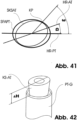
- An ellipse consists of all points whose sum is equal to the distance from two fixed points F 1 and F 2 ( Fig. 43 ). The sum is in Fig. 43 S 1 + S 2 . If such a geometry is used for the contact pin formed on the mounting part and for the recess in the post part and if the dimensions are coordinated with each other, two positioning options arise. In a particularly advantageous design, the contact pin on the mounting part and the recess in the post part are conical.
- the length of all main directions is the same, the length of all secondary directions is the same, the angles between the neighboring main directions are the same, the angles between the neighboring secondary directions are the same, in a particularly favorable embodiment the angles between the neighboring main directions and the secondary directions are half the size of the angles between the neighboring main directions and the angles between the neighboring Secondary directions, the number of main and secondary directions is the same, the course between the main directions and secondary directions complies with the laws of an oval and, in addition, the curvature of the curve is different at every point between the main and secondary directions. This means that the number of main directions or secondary directions results in the number of positioning options in which there is a form and force connection.
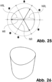
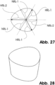
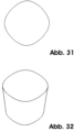
- a suitable geometry has a maximum of four main and four secondary directions ( Fig. 31 and Fig. 32 ), in particular three main and three secondary directions ( Fig. 25 and Fig. 26 ), and in the optimum two main and two secondary directions and is thus an ellipse ( Fig. 39 and Fig. 40 ). If four, five or six main and secondary directions are used, geometries are obtained as shown in the figures Fig. 31 to Fig. 36 which are also an inexpensive version.
- the difference in length between the main and secondary directions results in an eccentricity. If the secondary direction is too small in relation to the main direction, the curvature changes from convex to concave and the conditions of the oval are no longer met (e.g. Fig. 37 and Fig. 38 ). Due to manufacturing tolerances, there is a high risk of the connection becoming leaky. The contact pressure between the superstructure part and the post part also becomes uneven, which facilitates the mobility between the superstructure part and the post part. In addition, the difference between the main direction length and the secondary direction length becomes larger, which has a negative effect on the strength of the connection and the individual components. Extensive studies have shown that the secondary directions should preferably have the following percentage length ranges of the main directions.
- the connecting screw which fixes the superstructure part to the post part only engages when the rotary self-centring can occur purely through the forces and/or moments generated by the connecting screw.
- the thread of the connecting screw has not yet reached the thread in the post part. Consequently, the lifting height of the superstructure part in the post part with a rotational angular offset between them is greater than the usable and common thread length between the connecting screw and the post part.
- the connecting screw does not engage the thread of the post part until the forces and/or moments caused by the connecting screw are sufficient for the rotational self-centering of the superstructure part in the post part.
- the geometries of the contact pin molded onto the superstructure part and the molded recess provided for this purpose in the post part, the eccentricities, the conical contact pin length and the cone angle are dimensioned in such a way that the contact pin can penetrate at least a small amount, advantageously at least 0.1 mm and in particular at least 0.5 mm, into the molded recess provided for this purpose in the post part with each rotation about its own axis. This makes positioning the superstructure part in the post part considerably easier.
- the contact pin formed onto the structural part in this example elliptical and conical
- the post part which is also elliptical, conical and has a geometry adapted to the contact pin
- a positive connection and surface contact of the elliptical and conical surfaces can only occur if the main directions of the contact pin and the main directions of the molded recess are parallel (thus the secondary directions of the contact pin are also parallel to the secondary directions of the molded recess) and the axes of the contact pin and the molded recess are axially aligned with one another.
- the contact pin can penetrate the deepest into the molded recess and surface contact can be achieved between the two.
- the lifting height ⁇ H as a function of the contact angle w can be calculated as follows.
- a connection formed in this way combines a tight coupling point, high rotational strength and high strength against axial and extra-axial forces, moments and bending moments in a very short construction height and without changing its shape or external design over the length of the common contact point between the post part and the abutment part, apart from the conical inclination.
- the impression posts engage in the post part, the easier it is to remove the impression including the impression posts.
Landscapes
- Health & Medical Sciences (AREA)
- Oral & Maxillofacial Surgery (AREA)
- Orthopedic Medicine & Surgery (AREA)
- Dentistry (AREA)
- Epidemiology (AREA)
- Life Sciences & Earth Sciences (AREA)
- Animal Behavior & Ethology (AREA)
- General Health & Medical Sciences (AREA)
- Public Health (AREA)
- Veterinary Medicine (AREA)
- Engineering & Computer Science (AREA)
- Ceramic Engineering (AREA)
- Dental Prosthetics (AREA)
- Dental Preparations (AREA)
Description
Die Erfindung bezieht sich auf ein in einen Kieferknochen einbringbares Pfostenteil eines Dentalimplantats sowie ein ein solches Pfostenteil umfassendes Dentalimplantat.The invention relates to a post part of a dental implant that can be inserted into a jawbone, as well as to a dental implant comprising such a post part.
Dentalimplantate sind in vielfältigen Formen bekannt. Sie werden üblicherweise anstelle eines extrahierten oder ausgefallenen Zahnes in den Kieferknochen eingesetzt, um dort nach einer Einheilphase von drei bis vier Monaten ein als Zahnersatz dienendes prothetisches Teil oder eine Krone zu halten. Dazu ist ein derartiges Dentalimplantat üblicherweise als geeignet geformter Metallkörper ausgebildet, wobei das Pfostenteil üblicherweise durch Einschrauben an der vorgesehen Stelle in den Kieferknochen eingesetzt wird. Das Pfostenteil weist dabei in der Regel am apikalen Ende ein zumeist selbstschneidendes Schraubengewinde auf, mit welchem das Pfostenteil in das entsprechend präparierte Implantatbett eingesetzt wird.Dental implants are known in many different forms. They are usually inserted into the jawbone in place of an extracted or lost tooth in order to hold a prosthetic part or a crown that serves as a tooth replacement after a healing phase of three to four months. For this purpose, such a dental implant is usually designed as a suitably shaped metal body, with the post part usually being inserted into the jawbone at the intended location by screwing it in. The post part usually has a self-tapping screw thread at the apical end, with which the post part is inserted into the appropriately prepared implant bed.
Ein derartiges Dentalimplantat ist üblicherweise grundsätzlich zweiteilig aufgebaut und umfasst das zur Einbringung in den Kieferknochen vorgesehene Pfostenteil und ein zugeordnetes Aufbauteil, an das das als Prothese oder dergleichen vorgesehene Zahnersatzstück anbringbar ist. Das Pfostenteil und ebenso das Kopf- oder Aufbauteil bestehen üblicherweise aus Metall oder einer Keramik, und zwar insbesondere aus Titan, Zirkon, einer Titanlegierung, Zirkonlegierung, einer titanhaltigen Legierung, einer zirkonhaltigen Legierung, einer Zirkonoxid-Aluminiumoxid-Keramik oder einer Keramik, die entweder Zirkonoxid oder Aluminiumoxid beinhaltet oder mindestens eine der Keramiken als Hauptbestandteil aufweist. Darüber hinaus können Keramiken eingesetzt werden, die auf Silizium- oder Siliziumoxidbasis aufgebaut sind und z. B. Stickstoff, Wasserstoff, Kohlenstoff oder Wolfram beinhalten. Das Pfostenteil ist an seiner Außenseite üblicherweise mit einem Gewinde versehen, welches als selbstschneidendes oder auch als nicht selbstschneidendes Gewinde ausgeführt sein kann. Das Pfostenteil wird üblicherweise in einem entsprechend aufbereiteten Implantatbett des Kieferknochens verankert. Die Konstruktion des im Außenbereich des Pfostenteils vorgesehenen Gewindes ist dabei üblicherweise für eine hohe Primärstabilität der Anordnung und eine gleichmäßige Weiterleitung der bei der Kaubelastung des Dentalimplantats auftretenden Kräfte in den Kieferknochen ausgelegt.Such a dental implant is usually basically constructed in two parts and comprises the post part intended for insertion into the jawbone and an associated abutment part to which the dental prosthesis intended as a prosthesis or the like can be attached. The post part and also the head or abutment part are usually made of metal or a ceramic, in particular titanium, zirconium, a titanium alloy, zirconium alloy, a titanium-containing alloy, a zirconium-containing alloy, a zirconium oxide-aluminium oxide ceramic or a ceramic that contains either zirconium oxide or aluminum oxide or has at least one of the ceramics as a main component. In addition, ceramics can be used that are based on silicon or silicon oxide and contain, for example, nitrogen, hydrogen, carbon or tungsten. The post part is usually provided with a thread on its outside, which can be used as a self-tapping or can be designed as a non-self-tapping thread. The post part is usually anchored in an appropriately prepared implant bed in the jawbone. The design of the thread provided in the outer area of the post part is usually designed for high primary stability of the arrangement and an even transmission of the forces that occur when the dental implant is masticated into the jawbone.
Das Aufbauteil, das üblicherweise an seinem oberen Bereich mit einer Krone, einer anderen prothetischen Versorgung oder dergleichen in an sich bekannter Weise ausgestattet wird, ist üblicherweise über eine geeignet gewählte Verbindungsschraube mit dem Pfostenteil verschraubt. Bei der Einbringung wird dabei üblicherweise das Gewinde der Verbindungsschraube in ein zugeordnetes Innengewinde des Pfostenteils eingeschraubt. Der Schraubenkopf der Verbindungsschraube presst dabei beim Einschrauben über eine Stirnsenkung des Aufbauteils dieses auf das Pfostenteil. Das Aufbauteil kann aber auch in das Pfostenteil eingepresst werden und lediglich über eine Verklemmung fixiert werden, oder durch eine Zementiereung/Verklebung fixiert werden.The abutment part, which is usually fitted with a crown, another prosthetic device or the like on its upper part in a known manner, is usually screwed to the post part using a suitably selected connecting screw. When inserted, the thread of the connecting screw is usually screwed into an associated internal thread of the post part. When screwed in, the screw head of the connecting screw presses the abutment part onto the post part via a countersunk face. The abutment part can also be pressed into the post part and only fixed using a clamp, or fixed using cementing/bonding.
Zur Stabilisierung dieser Anordnung ist üblicherweise am Aufbauteil ein Kontaktstift angeformt, der formschlüssig in eine zugeordnete Formausnehmung im Pfostenteil einbringbar ist. Damit kann das Aufbauteil über den Kontaktstift in die Formausnehmung im Pfostenteil eingesteckt werden, wobei anschließend üblicherweise die mechanische Fixierung über das Anziehen der Verbindungsschraube erfolgt. Selbstverständlich kann stattdessen auch in der Art einer umgekehrten Anordnung der Kontaktstift auch am Pfostenteil angeformt und die Formausnehmung im Aufbauteil angebracht sein. Die nachfolgenden Ausführungen beziehen sich auf die weiter verbreitete Variante, bei der der Kontaktstift am Aufbauteil und die Formausnehmung im Pfostenteil eingebracht ist; der Gegenstand der Erfindung umfasst selbstverständlich aber auch die entsprechende andere Variante in umgekehrter Anordnung, bei der der Kontaktstift am Pfostenteil und die Formausnehmung im Aufbauteil angeordnet sind.To stabilize this arrangement, a contact pin is usually molded onto the mounting part, which can be inserted into an associated molded recess in the post part in a form-fitting manner. The mounting part can then be inserted into the molded recess in the post part via the contact pin, with mechanical fixing then usually taking place by tightening the connecting screw. Of course, instead of this, the contact pin can also be molded onto the post part and the molded recess can be installed in the mounting part in a reverse arrangement. The following explanations refer to the more common variant in which the contact pin is installed on the mounting part and the molded recess in the post part; however, the subject matter of the invention naturally also includes the corresponding other variant in a reverse arrangement in which the contact pin is arranged on the post part and the molded recess in the mounting part.
Im Hinblick auf die bei der Kaubelastung auftretenden Kräfte und die gewünschte Langlebigkeit bei der Verwendung eines derartigen Dentalimplantats ist die mechanische Stabilität der Anordnung gegenüber verschiedenartigen Belastungen von besonderer Bedeutung. Insbesondere soll dabei in der Regel auch einer Rotation oder Verdrehung zwischen dem Aufbauteil und dem Pfostenteil durch äußere Kräfte, meist bedingt durch die Kaubelastung, entgegengewirkt werden. Dazu wird üblicherweise eine mechanische Indizierung in Form einer mechanischen Sperre verwendet, oder es wird die Flächenpressung zwischen dem Aufbauteil und dem Pfostenteil geeignet gewählt. Zur Indizierung und zur Vermeidung der Rotation des Aufbauteils auf dem Pfostenteil kann insbesondere eine geeignete Konturierung des Querschnitts des Kontaktstifts einerseits und der diesem zugeordneten Formausnehmung andererseits vorgesehen sein, um die genannte mechanische Sperre zu bilden. Üblicherweise sind dazu der Kontaktstift und dementsprechend auch die Formausnehmung im Querschnitt sechskantförmig ausgeführt. Alternativ sind aber auch Ausführungen als Torks oder so genannte Vielzahlsysteme mit variierender Elementanzahl und variierender Geometrie bekannt.In view of the forces occurring during chewing and the desired longevity when using such a dental implant, the mechanical stability of the arrangement against various types of loads is of particular importance. Importance. In particular, rotation or twisting between the abutment part and the post part due to external forces, usually caused by chewing loads, should also be counteracted. For this purpose, mechanical indexing in the form of a mechanical lock is usually used, or the surface pressure between the abutment part and the post part is suitably selected. For indexing and to prevent rotation of the abutment part on the post part, suitable contouring of the cross section of the contact pin on the one hand and the molded recess associated with it on the other hand can be provided in order to form the mechanical lock mentioned. For this purpose, the contact pin and accordingly also the molded recess are usually hexagonal in cross section. Alternatively, designs as Torks or so-called multiple systems with varying numbers of elements and varying geometry are also known.
Abhängig von der Einbringstelle des Dentalimplantats (Frontzahn-, Seitenzahnbereich, Unterkiefer, Oberkiefer), der Knochensubstanz, der Restbezahnung, Verlauf und Position der Gefäße und Nerven ist es dem Behandler jedoch nicht immer möglich, die Bohrung für das Pfostenteil oder Implantat übereinstimmend mit der Achse der vorgesehenen prothetischen Versorgung, also insbesondere der Krone oder dergleichen, zu bohren. Dementsprechend ist es möglich, dass ein gerade oder linear ausgeführtes oder ausgerichtetes Pfostenteil oder Implantat und/oder ein gerade oder linear ausgeführtes Aufbauteil nicht den anatomischen Erfordernissen des Patienten und seiner Behandlung genügen. Um diesem Problem entgegenzuwirken, werden bedarfsweise auch abgewinkelte oder so genannte angulierte Aufbauteile verwendet.Depending on the insertion site of the dental implant (front teeth, side teeth, lower jaw, upper jaw), the bone substance, the remaining teeth, the course and position of the vessels and nerves, it is not always possible for the practitioner to drill the hole for the post part or implant in line with the axis of the intended prosthetic treatment, in particular the crown or the like. Accordingly, it is possible that a straight or linearly designed or aligned post part or implant and/or a straight or linearly designed abutment part do not meet the anatomical requirements of the patient and his treatment. To counteract this problem, angled or so-called angulated abutments are also used if necessary.
Der in diesem Zusammenhang üblicherweise vorgesehen Knickwinkel liegt in der Regel in einem Bereich zwischen 10° und 30°, kann aber auch bis zu 45°- 60° betragen. Nach der Einbringung des Implantats, vorzugsweise nach der Einheilung der Pfostenteile, müssen bei derartigen Systemen zur Anfertigung der Krone, der Brücke oder anderer Prothesen die räumlichen und geometrischen Informationen der Restbezahnung (beispielsweise Antagonisten, mesial und distal der Insertionsstelle stehende Zähne), der Schleimhaut und des Pfostenteils oder Implantats oder des montierten Aufbauteils erfasst werden. Diese räumlichen und geometrischen Informationen sind notwendig, um die Krone, Brücke oder dergleichen passgenau und anatomisch optimiert zu fertigen. Zu diesem Zweck wird üblicherweise eine Abformung, vorzugsweise aus Silikon oder einem anderen dentalen Abformmaterial, von der Mundsituation angefertigt. Diese Abformung wird vorzugsweise mit Gips oder einem anderen dentalen Modellwerkstoff ausgegossen. Dieses Gipsmodell ist somit ein Duplikat der Mundsituation des Patienten/der Patientin. Es liefert dem Zahnarzt und/oder dem Zahntechniker die Informationen über die Position der Restbezahnung, der Schleimhaut und des inserierten Pfostenteils oder Implantats.The bending angle usually provided in this context is generally in a range between 10° and 30°, but can also be up to 45°-60°. After the implant has been inserted, preferably after the post parts have healed, the spatial and geometric information of the remaining teeth (for example antagonists, teeth mesial and distal to the insertion site), the mucous membrane and the post part or implant or the mounted abutment part must be recorded in such systems for the manufacture of the crown, bridge or other prostheses. This spatial and geometric information is necessary in order to manufacture the crown, bridge or the like with a precise fit and anatomically optimized. For this purpose, an impression is usually made of the oral situation, preferably from silicone or another dental impression material. This impression is preferably cast with plaster or another dental model material. This plaster model is thus a duplicate of the patient's oral situation. It provides the dentist and/or dental technician with information about the position of the remaining teeth, the mucous membrane and the inserted post part or implant.
Zur Verbesserung der Übertragung von Position und Geometrie der inserierten Pfostenteile oder Implantate werden vorzugsweise spezielle Abformpfosten aus Metall und/oder Kunststoff auf die inserierten Pfostenteile oder Implantate gesteckt und/oder geschraubt. Anschließend wird die Abformung im Mund vorzugsweise mit Silikon angefertigt. Nach der Aushärtung des Abformmaterials verbleibt der Abformpfosten bei der Abdruckentnahme entweder auf dem Implantat oder wird mit der Abformung entnommen. Beim Ausgießen der Abformung muss der Abformpfosten oder Aufbaupfosten in der Abformung platziert werden und mit einem Laborimplantat verbunden sein. Dieses Laborimplantat besitzt bzgl. der Verbindung und geometrisch in Richtung des Abformpfostens oder Aufbaupfostens gleiche oder ähnliche geometrische Gestalt wie das inserierte Pfostenteil oder Implantat. Nach dem Ausgießen der Abformung mit integriertem Abformpfosten oder Aufbaupfosten und integriertem Laborimplantat erhält man ein Gipsmodell mit eingegossenem Laborimplantat.To improve the transfer of position and geometry of the inserted post parts or implants, special impression posts made of metal and/or plastic are preferably inserted and/or screwed onto the inserted post parts or implants. The impression is then made in the mouth, preferably with silicone. After the impression material has hardened, the impression post either remains on the implant when the impression is taken or is removed with the impression. When pouring the impression, the impression post or abutment post must be placed in the impression and connected to a laboratory implant. This laboratory implant has the same or a similar geometric shape as the inserted post part or implant in terms of the connection and geometrically in the direction of the impression post or abutment post. After pouring the impression with integrated impression post or abutment post and integrated laboratory implant, a plaster model with a cast-in laboratory implant is obtained.
Besitzt das verwendete Implantatsystem eine Indizierung, so wurde diese vom Patientenmund auf das Gipsmodell übertragen. Basierend auf diesem Gipsmodell wird die prothetische Versorgung des Implantats oder der Implantate geplant und gefertigt. Hierbei nimmt die rotatorische Position des Aufbauteils auf dem Implantat eine entscheidende Rolle ein. Besitzt das verwendete Implantatsystem eine Indizierung, so sind die Positioniermöglichkeiten des Aufbauteils auf dem Laborimplantat begrenzt. Bei einer Sechskantverbindung sind es sechs Positioniermöglichkeiten. Bei einem Implantatsystem ohne Indizierung können alle Positionen zwischen 0° und 360° verwendet werden. Nach der Fertigung des Zahnersatzes erfolgt meistens eine Anprobe im Patientenmund. Bei dieser Anprobe oder der endgültigen Eingliederung des prothetischen Zahnersatzes muss der Behandler das Aufbauteil und alle weiteren prothetischen Elemente im Patientenmund in der gleichen Position wie auf dem Gipsmodell eingliedern.If the implant system used has an index, this was transferred from the patient's mouth to the plaster model. The prosthetic restoration of the implant or implants is planned and manufactured based on this plaster model. The rotational position of the abutment on the implant plays a decisive role here. If the implant system used has an index, the positioning options for the abutment on the laboratory implant are limited. With a hexagonal connection, there are six positioning options. With an implant system without an index, all positions between 0° and 360° can be used. After the denture has been manufactured, a fitting is usually carried out in the patient's mouth. During this fitting or the final integration of the prosthetic denture The dentist must integrate the abutment and all other prosthetic elements in the patient's mouth in the same position as on the plaster model.
Derartigen Systemen ist die korrekte rotatorische Ausrichtung des Zahnersatzes im Patientenmund nach erfolgter Behandlung von besonderer Bedeutung. Andererseits soll aber üblicherweise die eigentliche Behandlung, also die Einbringung des mit dem Zahnersatz versehenen Aufbauteils in den Patientenmund durch Verbindung mit dem eingewachsenen Pfostenteil, möglichst kurz gehalten werden, um den Patienten während der Behandlung nicht zu sehr zu strapazieren. Um beide Bestrebungen möglichst weit gehend erfüllen zu können, kann das Aufbauteil eines derartigen Implantatsystems mehrstückig ausgeführt sein, wobei die das Aufbauteil bildenden Teilstücke grundsätzlich frei zueinander rotierbar ausgebildet sind. In derartigen Systemen kann durch geeignete Abnahme der Mundsituation die korrekte Ausrichtung des Aufbauteils und damit des Zahnersatzes im Labor vorgenommen und auch geeignet vorbereitet werden. Nach erfolgter laborseitiger Fertigstellung des Aufbauteils durch Zusammenfügen der Teilstücke in korrekter Orientierung kann sodann die Einbringung in den Patientenmund auf der Grundlage einer zuvor vorgenommenen Indizierung erfolgen. Dazu ist der Kontaktstift, mit dem das zusammengesetzte Aufbauteil in das Pfostenteil eingebracht wird, üblicherweise geeignet indiziert und in mehrzähliger Symmetrie ausgeführt, so dass bei der Einbringung nur eine vergleichsweise geringe Anzahl möglicher Orientierungen auswählbar und somit die korrekte Einstellung der räumlichen Ausrichtung auf besonders einfache Weise während der Einbringung möglich ist. Derartige Implantatsysteme mit mehrteiliger Ausführung des Aufbauteils sind beispielsweise aus der
Wie sich nunmehr aber herausgestellt hat, kann auch bei derartigen Implantatsystemen trotz der vergleichsweise großen Vorteile, die die laborseitige Voreinstellung der Orientierung bietet, aus der mehrteiligen Ausführung des Aufbauteils eine zu große Bauhöhe oder -länge des Aufbauteils resultieren, so dass ein derartiges Implantatsystem möglicherweise aus Platzgründen nicht an allen therapeutisch erforderlichen Stellen geeignet einsetzbar sein könnte.However, it has now become apparent that, despite the comparatively great advantages offered by the laboratory-side presetting of the orientation, the multi-part design of the abutment part can also result in an excessively high or long construction of the abutment part in such implant systems, so that such an implant system may not be suitable for use in all therapeutically required locations due to space constraints.
Als ein weiteres Auslegungsziel für derartige Implantatsysteme ist darüber hinaus in der Regel zu berücksichtigen, dass eine vergleichsweise hohe Dichtigkeit beim mechanischen Kontakt zwischen Aufbauteil und Pfostenteil gewährleistet sein sollte, um ein Eindringen von Keimen oder dergleichen in den inneren Implantatbereich zu vermeiden. Damit soll insbesondere das Risiko von Entzündungen des Gewebes um das Dentalimplantat herum, gerade in den von außen dann nicht mehr ohne weiteres zugänglichen Gewebebereichen, so gering wie möglich gehalten werden.Another design goal for such implant systems is to ensure that the mechanical contact between the abutment part and the post part is relatively tight, in order to prevent germs or similar from penetrating the inner implant area. This is intended to keep the risk of inflammation of the tissue around the dental implant as low as possible, particularly in the tissue areas that are no longer easily accessible from the outside.
Der Erfindung liegt daher die Aufgabe zugrunde, ein Dentalimplantat der oben genannten Art bzw. dessen Komponenten derart auszugestalten, dass einerseits auf besonders einfache und zuverlässige Weise eine geeignete Indizierung des Implantats ermöglicht ist, wobei andererseits selbst bei gering gehaltener Bauhöhe eine besonders hohe Dichtigkeit zwischen Aufbauteil und Pfostenteil ermöglicht sein soll.The invention is therefore based on the object of designing a dental implant of the above-mentioned type or its components in such a way that, on the one hand, a suitable indexing of the implant is made possible in a particularly simple and reliable manner, while on the other hand, a particularly high degree of tightness between the superstructure part and the post part should be made possible even with a low construction height.
Diese Aufgabe wird erfindungsgemäß gelöst, indem das Pfostenteil gemäß den Merkmalen des Anspruchs 1 oder 2 und/oder das Dentalimplantat gemäß den Merkmalen des Anspruchs 3 oder 4 ausgeführt sind. Die Verbindung zwischen dem Pfostenteil und dem Aufbau ist konisch ausgebildet. Dabei sollen im Verbindungsbereich der Komponenten der Querschnitt des Kontaktstifts und der Querschnitt der diesem zugeordneten Formausnehmung jeweils mindestens drei Hauptrichtungen aufweisen, in denen der Halbmesser jeweils einen relativen Maximalwert einnimmt, wobei die Außenkontur des Querschnitts derart gewählt ist, dass sie an jedem Punkt genau eine Tangente aufweist. Weiterhin ist die Außenkontur dabei derart gewählt, dass sie von jeder beliebigen Geraden höchstens in zwei Punkten geschnitten wird, und zwischen jeweils zwei Hauptrichtungen einem Ovalsegment entspricht.This object is achieved according to the invention in that the post part is designed according to the features of
Vorteilhafte Ausgestaltungen der Erfindung sind Gegenstand der Unteransprüche. Die Erfindung geht von der Überlegung aus, dass gerade im Hinblick auf die vollständige Abdeckung möglicher Einbringungsszenarien die Bauhöhe des Aufbauteils als solches besonders gering gehalten werden sollte, indem das Aufbauteil grundsätzlich einstückig ausgeführt sein sollte. Um dennoch auf einfache Weise eine geeignete Indizierung bereitzustellen, die eine aufwändige Ausrichtung und Justierung des vorbereiteten Implantats im Patientenmund erübrigt, sollte über die Vorgabe eines geeigneten Querschnitts des Kontaktstifts und der diesen zugeordneten Formausnehmung im Pfostenteil eine entsprechende Ausrichtung des Aufbauteils sichergestellt sein. Dazu ist vorgesehen, dass der Halbmesser des Querschnitts des Kontaktstifts und dementsprechend der daran angepassten Formausnehmung im Pfostenteil, also der Radius oder Abstand der Außenkontur der Querschnittsfläche von deren Zentral- oder Mittelpunkt, insbesondere den Schwerpunkt, bezogen auf eine Rotation oder Verschwenkung um diesen, nicht konstant sein sollte, sondern in mindestens drei Hauptrichtungen, Maximalwerte aufweisen sollte. Beim Einbringen des Kontaktstifts in die Formausnehmung werden diese Hauptrichtungen von Kontaktstift einerseits und Formausnehmung andererseits in Überlappung gebracht, so dass die gewünschte Ausrichtung des am Kontaktstift angebrachten Aufbauteils relativ zum Pfostenteil eintritt.Advantageous embodiments of the invention are the subject of the dependent claims. The invention is based on the consideration that, particularly with regard to the complete coverage of possible insertion scenarios, the height of the abutment part as such should be kept particularly low by the abutment part being designed as a single piece. In order to nevertheless provide a suitable indexing in a simple manner, which makes complex alignment and adjustment of the prepared implant in the patient's mouth unnecessary, the specification of a suitable cross-section of the contact pin and the associated shaped recess in the post part, a corresponding alignment of the structural part must be ensured. For this purpose, it is intended that the radius of the cross section of the contact pin and accordingly of the corresponding shaped recess in the post part, i.e. the radius or distance of the outer contour of the cross-sectional area from its central or midpoint, in particular the center of gravity, in relation to a rotation or pivoting about it, should not be constant, but should have maximum values in at least three main directions. When the contact pin is inserted into the shaped recess, these main directions of the contact pin on the one hand and the shaped recess on the other hand are brought into overlap, so that the desired alignment of the structural part attached to the contact pin relative to the post part occurs.
Der jeweilige Maximalwert des Halbmessers in Abhängigkeit vom Rotationswinkel um den Mittel- oder Schwerpunkt der Querschnittsfläche kann dabei der absolute Maximal- oder Höchstwert des Halbmessers oder auch ein lokaler oder relativer Maximalwert des Halbmessers sein, beim der Halbmesser in der jeweiligen Hauptrichtung einen größeren Wert annimmt als in unmittelbar benachbarten Ausrichtungen.The respective maximum value of the radius depending on the angle of rotation around the center or center of gravity of the cross-sectional area can be the absolute maximum or highest value of the radius or also a local or relative maximum value of the radius, where the radius assumes a larger value in the respective main direction than in immediately adjacent orientations.
Um in einem derartigen System, bei dem die Ausrichtung oder Indizierung des Aufbauteils relativ zum Pfostenteil konturbedingt erfolgt, die gewünschte hohe Dichtigkeit im mechanischen Kontaktbereich zwischen Aufbauteil und Pfostenteil, also insbesondere zwischen Kontaktstift und Innenfläche der Formausnehmung, besonders zuverlässig zu gewährleisten, ist vorgesehen, die Außenkontur der Querschnittsfläche des Kontaktstifts und entsprechend der Formausnehmung zwischen den genannten Hauptrichtungen geeignet zu wählen. Dazu ist die Außenkontur im Wesentlichen eckenfrei ausgeführt, so dass im Querschnitt jeder Punkt der Außenkontur genau eine Tangente aufweist.In order to ensure the desired high level of tightness in the mechanical contact area between the superstructure part and the post part, i.e. in particular between the contact pin and the inner surface of the mold recess, in a particularly reliable manner in such a system, in which the alignment or indexing of the superstructure part relative to the post part is determined by the contour, the outer contour of the cross-sectional area of the contact pin and the mold recess are selected appropriately between the main directions mentioned. For this purpose, the outer contour is essentially designed to be corner-free, so that in the cross section every point of the outer contour has exactly one tangent.
Zudem ist eine besonders hohe Dichtigkeit erreichbar, indem in den Segmenten zwischen den Hauptrichtungen die Außenkontur bauchig oder nach außen gekrümmt oder gewölbt ausgestaltet ist. Durch diese Ausgestaltung ist bewirkt, dass bei einem Einbringen des Kontaktstifts in die Formausnehmung Formfehler, also beispielsweise produktionsbedingte lokale Konturabweichungen oder dergleichen zwischen den Querschnitten durch Verspannungen und daraus resultierende lokale Verformungen ausgeglichen werden und sich die Querschnitte aneinander angleichen. Die nach außen gekrümmte oder bauchige Ausgestaltung der Kontursegmente resultiert dabei in einer Analogie zu einem Kriterium eines Flächenovals, dass nämlich jede beliebige Gerade die jeweilige Querschnittsfläche in höchstens zwei Punkten schneidet.In addition, a particularly high level of tightness can be achieved by making the outer contour bulging or curved outwards or arched in the segments between the main directions. This design ensures that when the contact pin is inserted into the mold recess, molding errors, such as production-related local contour deviations or the like between the cross sections are compensated for by tensions and the resulting local deformations and the cross sections adjust to one another. The outwardly curved or bulbous design of the contour segments results in an analogy to a criterion of a surface oval, namely that any straight line intersects the respective cross-sectional area at a maximum of two points.
Die Außenkontur des Querschnitts ist zudem derart gewählt, dass sie in den Bereichen zwischen jeweils zwei Hauptrichtungen einem Ovalsegment entspricht. Mit anderen Worten: die Außenkontur in den Segmenten erfüllt zwischen jeweils zwei Hauptrichtungen zusätzlich auch noch das zweite Kriterium eines Flächenovals, nämlich dass für jeden Punkt des Kontursegments genau eine Tangente existiert. Damit weist die Außenkontur im jeweiligen Segment einen vergleichsweise glatten Verlauf ohne Bildung von Ecken auf.The outer contour of the cross-section is also chosen in such a way that it corresponds to an oval segment in the areas between two main directions. In other words: the outer contour in the segments also meets the second criterion of a surface oval between two main directions, namely that there is exactly one tangent for each point of the contour segment. The outer contour in the respective segment therefore has a comparatively smooth course without the formation of corners.
Das Dentalimplantat ist zudem derart ausgestaltet, dass der an das Aufbauteil angeformte Kontaktstift und die diesem zugeordnete Formausnehmung im Pfostenteil jeweils vollständig unter Vermeidung von Ecken in der Querschnittskontur ausgebildet sind. Damit erfüllt der jeweilige Querschnitt auch in den Punkten der Außenkontur in den jeweiligen Hauptrichtungen das zweite Kriterium eines Flächenovals, dass nämlich auch für diese Punkte genau eine Tangente existiert, und bildet somit in seiner Gesamtheit ein Oval. Damit weist die Außenkontur auch in den jeweiligen Hauptrichtungen einen gerundeten Verlauf auf. Gerade durch diesen auch in den Hauptrichtungen gegebenen vergleichsweise runden Verlauf ist gewährleistet, dass beim Einbringen des Kontaktstifts in die Formausnehmung eventuelle geringfügige Fehlausrichtungen in der Orientierung selbsttätig in der Art einer geführten Selbstzentrierung ohne Versperrungen, Klemmungen oder Verhakungen korrigiert werden.The dental implant is also designed in such a way that the contact pin formed onto the abutment part and the molded recess associated with it in the post part are each completely formed in the cross-sectional contour, avoiding corners. This means that the respective cross-section also meets the second criterion of a surface oval at the points of the outer contour in the respective main directions, namely that there is exactly one tangent for these points, and thus forms an oval as a whole. This means that the outer contour also has a rounded course in the respective main directions. It is precisely this comparatively round course, which is also present in the main directions, that ensures that when the contact pin is inserted into the molded recess, any minor misalignments in orientation are automatically corrected in the manner of a guided self-centering without blockages, clamping or snagging.
Um zudem eine grundsätzlich besonders gewünschte hohe mechanische Stabilität des montierten Systems gegenüber Verdrehungen auf besonders einfache Weise sicherzustellen, sollte der Querschnitt des Kontaktstifts und entsprechend auch der zugeordneten Formausnehmung in besonders vorteilhafter Weiterbildung in der Art einer zwei- oder mehrzähligen Symmetrie gewählt werden. Eine zweizählige Symmetrie ist dabei erreichbar, indem der Querschnitt vorteilhafterweise elliptisch ausgeführt ist, wohingegen eine dreizählige Symmetrie erreichbar ist, indem der Querschnitt in alternativer vorteilhafter Ausgestaltung als Trioval ausgeführt ist.In order to ensure a fundamentally particularly desired high mechanical stability of the assembled system against twisting in a particularly simple manner, the cross section of the contact pin and accordingly also of the associated mold recess should, in a particularly advantageous development, be designed in the form of a two- or multi-fold symmetry. A two-fold symmetry can be achieved by making the cross section advantageously elliptical, whereas a three-fold symmetry can be achieved by making the cross section in an alternative advantageous configuration as a trioval.
Durch die Querschnittswahl in der genannten Art ist insbesondere erreicht, dass eine im Wesentlichen zwei- bzw. dreizählige Symmetrie des Querschnitts vorliegt, so dass Fehler bei der Justierung des Implantats während des Einbringens in den Patientenmund nahezu ausgeschlossen sind. Bei zweizähliger Symmetrie des elliptischen oder ovalen Querschnitts kann diese, wie insbesondere für eine Ellipse (nicht beansprucht) üblich, im Wesentlichen durch zwei Hauptachsen beschrieben werden, wobei die erste Hauptachse der Ellipse oder des Ovals die Hauptrichtung mit maximalem Durchmesser und die zweite, in der Regel senkrecht zur ersten Hauptachse stehende Hauptachse die Nebenrichtung mit minimalem Durchmesser der Ellipse oder des Ovals beschreibt.By selecting the cross-section in the manner mentioned, it is achieved in particular that there is essentially a two- or three-fold symmetry of the cross-section, so that errors in adjusting the implant during insertion into the patient's mouth are almost impossible. In the case of two-fold symmetry of the elliptical or oval cross-section, this can, as is usual in particular for an ellipse (not claimed), be essentially described by two main axes, whereby the first main axis of the ellipse or oval describes the main direction with maximum diameter and the second main axis, which is usually perpendicular to the first main axis, describes the secondary direction with minimum diameter of the ellipse or oval.
Wie sich überraschenderweise herausgestellt hat, ist durch eine geeignete Wahl der Geometrieparameter in einem derartigen System, insbesondere durch eine geeignete Wahl des Verhältnisses von maximalem Durchmesser zu minimalem Durchmesser, ein besonders günstiges Einbringungsverhalten des Systems erreichbar, bei dem in der Art einer Selbstzentrierung beim Einbringen des Kontaktstifts in die zugeordnete Formaus-nehmung eine korrekte Ausrichtung des Aufbauteils erfolgt. Dazu sind die Konturen der Querschnitte vorteilhafterweise jeweils derart gewählt, dass das Verhältnis von minimalem Durchmesser zu maximalem Durchmesser der Ellipse oder des Ovals mindestens 0,7 und höchstens 0,94, vorzugsweise mindestens 0,8 und höchstens 0,87, beträgt.As has surprisingly been found, by a suitable choice of the geometry parameters in such a system, in particular by a suitable choice of the ratio of maximum diameter to minimum diameter, a particularly favorable insertion behavior of the system can be achieved, in which the correct alignment of the structural part occurs in the form of self-centering when the contact pin is inserted into the associated mold recess. For this purpose, the contours of the cross sections are advantageously selected in such a way that the ratio of minimum diameter to maximum diameter of the ellipse or oval is at least 0.7 and at most 0.94, preferably at least 0.8 and at most 0.87.
Bei einer elliptischen Ausführung der jeweiligen Querschnitte können diese Parameter äquivalent auch durch die so genannte numerische Exzentrizität der Ellipse spezifiziert werden. Vorzugsweise beträgt dabei die numerische Exzentrizität der Ellipse zwischen 0,35 und 0,7, besonders vorteilhafterweise zwischen 0,4 und 0,5.In the case of an elliptical design of the respective cross-sections, these parameters can also be specified equivalently by the so-called numerical eccentricity of the ellipse. The numerical eccentricity of the ellipse is preferably between 0.35 and 0.7, particularly advantageously between 0.4 and 0.5.
Die Verbindung zwischen dem Pfostenteil und dem Aufbauteil ist konisch ausgebildet. Dazu sind sowohl der Kontaktstift des Aufbauteils in seiner Längsrichtung als auch der durch die zugeordnete Formausnehmung im Pfostenteil gebildete Aufnahmekanal für den Kontaktstift jeweils konisch ausgeführt. Gerade in Kombination mit dem elliptischen oder ovalen Querschnitt führt diese konische Ausgestaltung von Kontaktstift und Formausnehmung dazu, dass beim Einbringen des Kontaktstifts in die Formausnehmung noch vergleichsweise viel rotatorisches Spiel vorliegt, so dass eine exakte Ausrichtung oder Justierung des Aufbauteils in Relation zum Pfostenteil in diesem Moment noch nicht erforderlich ist. Vielmehr kann der Zahnarzt beim Einbringen das Aufbauteil vergleichsweise grob ausgerichtet einsetzen, da zu Beginn des Eintritts des Kontaktstifts in die Formausnehmung aufgrund der konischen Ausgestaltung beider Teile die Flächendifferenz und das damit bedingte rotatorische Spiel noch vergleichsweise groß sind.The connection between the post part and the mounting part is conical. For this purpose, both the contact pin of the mounting part in its longitudinal direction and the contact pin through the associated The receiving channel for the contact pin formed in the recess in the post part is conical. In combination with the elliptical or oval cross-section, this conical design of the contact pin and the recess means that there is still a relatively large amount of rotational play when the contact pin is inserted into the recess, so that exact alignment or adjustment of the abutment part in relation to the post part is not yet necessary at this point. Instead, the dentist can insert the abutment part in a relatively roughly aligned manner when inserting it, since when the contact pin first enters the recess, the difference in area and the resulting rotational play are still relatively large due to the conical design of both parts.
Beim weiteren Einschieben des Kontaktstifts in die Formausnehmung gleichen sich die Querschnittsgrößen hingegen zunehmend an, so dass sich das rotatorische Spiel automatisch in Folge des Einbringens verringert und damit eine zunehmend präzisere Ausrichtung des Aufbauteils in rotatorischer Richtung erfolgt. Bei vollständig eingeschobenem Kontaktstift, also sobald der Kontaktstift mechanischen und formschlüssigen Kontakt mit der Formausnehmung aufweist, ist dabei eine nahezu spielfreie, vollständig richtige Ausrichtung gewährleistet. Die konische Ausgestaltung der genannten Bauteile bewirkt zudem eine zusätzliche Hemmung oder Selbsthemmung der beiden Teile, die insbesondere bei angezogener Verbindungsschraube einen besonders zuverlässigen Form- und Kraftschluss zwischen den Komponenten herstellt und damit eine besonders hohe mechanische Stabilität des Gesamtsystem auch gegenüber Verdrehung bewirkt.As the contact pin is pushed further into the mold recess, the cross-sectional sizes become increasingly similar, so that the rotational play is automatically reduced as a result of the insertion and the assembly part is aligned more and more precisely in the rotational direction. When the contact pin is fully inserted, i.e. as soon as the contact pin has mechanical and positive contact with the mold recess, an almost play-free, completely correct alignment is guaranteed. The conical design of the components mentioned also causes additional locking or self-locking of the two parts, which creates a particularly reliable positive and frictional connection between the components, especially when the connecting screw is tightened, and thus ensures a particularly high level of mechanical stability of the entire system, even against twisting.
Damit ist zudem auch eine hoch präzise und zuverlässige Übertragung von Kräften und Drehmomenten nahezu frei von rotatorischem Spiel ermöglicht.This also enables highly precise and reliable transmission of forces and torques with almost no rotational play.
Um diesen gewünschten Effekt einer automatischen Selbstausrichtung des Aufbauteils beim Einbringen des Kontaktstifts in die Formausnehmung noch weiter zu begünstigen, ist der Konuswinkel für den Kontaktstift und/oder die Formausnehmung vorteilhafterweise zwischen 1° und 15°, vorzugsweise zwischen 4° und 10°, besonders bevorzugt etwa 6°, gewählt. Gerade durch eine derartige Parameterwahl und in besonderem Maße in Kombination mit den oben genannten Geometrieparametern für den Querschnitt, insbesondere durch die Abrundungen der Ecken im Querschnitt, ist eine besonders einfache und zuverlässige Handhabung des Systems gerade im Hinblick auf eine einfache und zügige Einbringung des Aufbauteils in das Pfostenteil gewährleistet.In order to further promote this desired effect of automatic self-alignment of the structural part when the contact pin is inserted into the mold recess, the cone angle for the contact pin and/or the mold recess is advantageously selected between 1° and 15°, preferably between 4° and 10°, particularly preferably about 6°. It is precisely through such a choice of parameters and in particular in combination with the above-mentioned geometric parameters for the cross-section, in particular through the rounding of the corners in the cross-section, that a particularly simple and reliable handling of the system is ensured, especially with regard to simple and rapid insertion of the superstructure part into the post part.
In weiterer vorteilhafter Ausgestaltung ist das Aufbauteil über eine Verbindungsschraube an das Pfostenteil montiert.In a further advantageous embodiment, the superstructure part is mounted to the post part via a connecting screw.
Die Ausgestaltung kann unter Zugrundelegung der vorstehend genannten Auslegungskriterien ein Dentalimplantat bereitgestellt werden, das bei der Montage eine besonders hohe Fehlersicherheit bietet, durch eine Kombination der genannten Kriterien miteinander. Ein solches Dentalimplantat umfasst ein in einen Kieferknochen einbringbares Pfostenteil und ein diesem zugeordnetes Aufbauteil, bei dem das Aufbauteil einen angeformten Kontaktstift aufweist, der formschlüssig in eine zugeordnete Formausnehmung im Pfostenteil einbringbar ist, wobei sowohl der Kontaktstift des Aufbauteils als auch die Formaus-nehmung im Pfostenteil sich verjüngend ausgeführt sind, und wobei der Querschnitt des Kontaktstifts und der Querschnitt der diesem zugeordneten Formausnehmung jeweils drei Hauptrichtungen, in denen der Halbmesser jeweils einen relativen Maximalwert einnimmt, und jeweils drei Nebenrichtungen, in denen der Halbmesser jeweils einen relativen Minimalwert einnimmt, aufweisen, wobei die Außenkontur des Querschnitts derart gewählt ist, dass sie an jedem Punkt genau eine Tangente aufweist, von jeder beliebigen Geraden höchstens in zwei Punkten geschnitten wird und in den Bereichen zwischen jeweils zwei Hauptrichtungen einem Ovalsegment entspricht, und wobei die Konturen der Querschnitte jeweils derart gewählt sind, dass das Verhältnis von minimalem Halbmesser zu maximalem Halbmesser mindestens 0,7 und höchstens 0,95 und der Verjüngungswinkel des Kontaktstifts und/oder der Formausnehmung zwischen 1° und 15° beträgt.The design can be based on the above-mentioned design criteria to provide a dental implant which offers a particularly high level of error resistance during assembly by combining the above-mentioned criteria. Such a dental implant comprises a post part that can be inserted into a jawbone and an abutment part associated therewith, in which the abutment part has a molded-on contact pin that can be inserted in a form-fitting manner into an associated mold recess in the post part, wherein both the contact pin of the abutment part and the mold recess in the post part are tapered, and wherein the cross section of the contact pin and the cross section of the mold recess associated therewith each have three main directions in which the radius each assumes a relative maximum value, and three secondary directions in which the radius each assumes a relative minimum value, wherein the outer contour of the cross section is selected such that it has exactly one tangent at each point, is intersected by any straight line at a maximum of two points and corresponds to an oval segment in the areas between each two main directions, and wherein the contours of the cross sections are each selected such that the ratio of minimum radius to maximum radius is at least 0.7 and at most 0.95 and the taper angle of the contact pin and/or the mold recess is between 1° and 15°.
In einem solchen Dentalimplantat ist besonders bevorzugt das Aufbauteil über eine Verbindungsschraube an das Pfostenteil montiert, wobei in weiterer vorteilhafter Ausgetaltung die Konturen der Querschnitte des Kontaktstifts und der Formausnehmung, der Verjüngungswinkel sowie die Länge der Verbindungsschraube derart gewählt sind, dass bei einer verdrehten Positionierung des Aufbauteils relativ zum Pfostenteil, bei der eine Hauptrichtung des Kontaktstifts parallel zu einer Nebenrichtung der Formausnehmung ausgerichtet ist, das Gewinde der Verbindungs-schraube nicht in das Gewinde im Pfostenteil eingreift.In such a dental implant, the abutment part is particularly preferably mounted to the post part via a connecting screw, wherein in a further advantageous embodiment the contours of the cross sections of the contact pin and the mold recess, the tapering angle and the length of the connecting screw are selected such that in the case of a twisted positioning of the abutment part relative to the post part, in which a main direction of the contact pin is parallel to a secondary direction of the The thread of the connecting screw does not engage with the thread in the post part.
Die mit der Erfindung erzielten Vorteile bestehen insbesondere darin, dass durch die geeignete Konturierung und Parametrierung des Querschnitts für den Kontaktstift des Aufbauteils und die zugehörige Formausnehmung im Pfostenteil (bzw. entsprechend umgekehrt) auf einfache und mechanisch stabile Weise eine zuverlässige Ausrichtung des geeignet vorbereiteten, ggf. mit Zahnersatz versehenen Aufbauteils bei der Einbringung in das Pfostenteil erreichbar ist. Damit kann die Behandlungsdauer für den Patienten bei der Einbringung des Aufbauteils in den Mundraum besonders kurz gehalten werden, wobei dennoch eine besonders hochwertige Ausrichtung des Zahnersatzes ermöglicht ist. Gerade durch die Kombination einer zum freien Ende hin sich verjüngenden Ausgestaltung des Aufnahmekanals für den Kontaktstift und den Kontaktstift selbst mit dem elliptischen oder ovalen Querschnitt von Kontaktstift und Aufnahmekanal kann zudem eine zuverlässige und einfach gehaltene Ausrichtung des Aufbauteils durch Einschieben des Kontaktstifts im Aufnahmekanal sichergestellt werden. Dabei ist insbesondere eine besonders hohe Positionsgenauigkeit erreichbar, die durch die aufgrund des Zusammenwirkens der Komponenten auftretende rotatorische Selbstzentrierung beim Einschieben des Kontaktstifts noch weiter begünstigt wird.The advantages achieved with the invention are in particular that, through the suitable contouring and parameterization of the cross section for the contact pin of the abutment part and the associated molded recess in the post part (or vice versa), a reliable alignment of the suitably prepared abutment part, possibly provided with a denture, can be achieved in a simple and mechanically stable manner when it is inserted into the post part. This means that the treatment time for the patient when the abutment part is inserted into the oral cavity can be kept particularly short, while a particularly high-quality alignment of the denture is still possible. It is precisely the combination of a design of the receiving channel for the contact pin and the contact pin itself that tapers towards the free end with the elliptical or oval cross section of the contact pin and receiving channel that ensures a reliable and simple alignment of the abutment part by inserting the contact pin in the receiving channel. In particular, a particularly high level of positioning accuracy can be achieved, which is further promoted by the rotary self-centering that occurs due to the interaction of the components when the contact pin is inserted.
Nur die Ausführungsbeispiele wie in den
- FIG. 1, 2
- schematisch ein Dentalimplantat,
- FIG. 3
- einen an einem Aufbauteil des Dentalimplantats nach
FIG. 1 angeformten Kontaktstift im Querschnitt, - FIG. 4
- die zur Aufnahme des Kontaktstifts mit elliptischem Querschnitt nach
FIG. 3 im Pfostenteil vorgesehene Formausnehmung, - FIG. 5-40
- jeweils paarweise eine alternative Querschnittsform für den Kontaktstift des Dentalimplants und die zugehörige Formausnehmung,
- FIG. 41
- schematisch eine Ellipse,
- FIG. 42
- einen in eine Formausnehmung eingebrachten Kontaktstift, und
- FIG. 43
- schematisch eine Ellipse.
- FIGS. 1, 2
- schematically a dental implant,
- FIG.3
- one on a part of the dental implant after
FIG.1 molded contact pin in cross section, - FIG.4
- which is designed to accommodate the contact pin with elliptical cross-section according to
FIG.3 recess provided in the post part, - FIG.5-40
- an alternative cross-sectional shape for the contact pin of the dental implant and the associated mold recess, each in pairs,
- FIG.41
- schematically an ellipse,
- FIG.42
- a contact pin inserted into a mold recess, and
- FIG.43
- schematically an ellipse.
Gleiche Teile sind in allen Figuren mit denselben Bezugszeichen versehen.Identical parts are provided with the same reference numerals in all figures.
Das in
Nach der Einbringung des Pfostenteils 2 in den Kieferknochen ist eine Einheilphase von 4 Wochen bis zu sechs Monaten vorgesehen, in der das Pfostenteil in das Gewebe und den Kieferknochen einwachsen soll. Anschließend kann in einem zweiten Behandlungsschritt das Aufbauteil 4 mit dem angebrachten Zahnersatzstück eingesetzt werden. Bei besonders günstigen Knochenverhältnissen und einer entsprechend hohen Primärstabilität kann die Versorgung mit dem Aufbauteil 4 und den weiteren prothetischen Komponenten auch im direkten Anschluss an die Insertion des Pfostenteils oder Implantats erfolgen.After the
Um auf einfache Weise eine mechanisch vergleichsweise stabile Verbindung zwischen dem Pfostenteil 2 und dem Aufbauteil 4 herstellen zu können, ist an das Aufbauteil 4 ein Kontaktstift 8 angeformt, der beim Zusammenfügen von Pfostenteil 2 und Aufbauteil 4 in eine einen Aufnahmekanal für den Kontaktstift 8 bildende Formausnehmung 10 im Pfostenteil 2 einbringbar ist. Die mechanische Verbindung von Pfostenteil 2 und Aufbauteil 4 erfolgt über eine zugeordnete Verbindungsschraube 12, deren Außengewinde 14 in ein im Pfostenteil 2 vorgesehenes Innengewinde 16 eingeschraubt wird. Der Schraubenkopf 18 der Verbindungsschraube 12 presst dabei das Aufbauteil 4 auf das Pfostenteil 2.In order to be able to easily create a mechanically comparatively stable connection between the
Das Dentalimplantat 1 ist gezielt dafür ausgelegt, bei geeigneter Vorbereitung des Aufbauteils 4 eine zuverlässige und mechanisch stabile rotatorische Ausrichtung des Aufbauteils 4 selbst beim Auftreten vergleichsweise hoher Kräfte, insbesondere durch die Kaubelastung, zu gewährleisten. Dabei soll insbesondere auch die Einbringung und das Eingliedern des mit dem Zahnersatzstück versehenen Aufbauteils 4 in das in dem Kieferknochen eingewachsene Pfostenteil 2 in verhältnismäßig kurzer Behandlungszeit erfolgen können.The
Dazu weisen im Ausführungsbeispiel der formschlüssig in die zugeordnete Formaus-nehmung 10 im Pfostenteil 2 einbringbare Kontaktstift 8 und auch die Formausnehmung 10 im Pfostenteil 2 jeweils einen elliptischen oder ovalen Querschnitt auf. Zudem sind sowohl der Kontaktstift 8 des Aufbauteils 4 als auch die Formausnehmung 10 im Pfostenteil 2 und der durch diesen gebildeten Aufnahmekanal für den Kontaktstift 8 jeweils konisch ausgeführt. Dabei verjüngt sich der freie Querschnitt sowohl des Kontaktstifts 8 als auch der Formausnehmung 10 in Richtung zum Ende des Pfostenteils 2 hin, so dass der durch die Formausnehmung 10 gebildete Aufnahmekanal im Pfostenteil 2 im Wesentlichen eine Art von trichterförmigem Kanal mit elliptischem oder ovalem Querschnitt bildet. Dadurch ist gewährleistet, dass der Querschnitt des Kontaktstifts 8 an dessen Ende eine im Vergleich zur von der Formausnehmung 10 gebildeten Eintrittsöffnung im Pfostenteil 2 vergleichsweise kleine Fläche aufweist, so dass beim Eintritt des Kontaktstifts 8 in die Formausnehmung 10 eine vergleichsweise große Flächendifferenz und somit ein vergleichsweise großes rotatorisches Spiel zwischen den genannten Komponenten besteht.For this purpose, in the exemplary embodiment, the
Dadurch ist beim Einbringen des Kontaktstifts 8 in die Formausnehmung 10 ausreichend, wenn das Aufbauteil 4 lediglich vergleichsweise grob in rotatorischer Richtung ausgerichtet ist. Durch den sich trichterförmig zusammenziehenden konischen Aufnahmekanal mit elliptischem oder ovalem Querschnitt erfolgt beim weiteren Einbringen des Kontaktstifts 8 in die Formausnehmung 10, also während des Einsetzens des Aufbauteils 4 in das Pfostenteil 2, eine zunehmende Angleichung der jeweiligen Querschnittsflächen, so dass der Kontaktstift 8 und damit das Aufbauteil 4 zunehmend durch den sich einstellenden Formschluss mechanisch geführt wird. Wenn schließlich der Kontaktstift 8 voll in die Formausnehmung 10 eingebracht ist und in dieser formschlüssig anliegt, bilden die Flächen einen durchgängigen Formschluss, so dass damit auch die rotatorische Ausrichtung des Aufbauteils 4 eindeutig festgelegt ist. Durch das Einbringen erfolgt somit bereits aufgrund der Formgebung und Konturierung von Kontaktstift 8 und Formausnehmung 10 eine selbsttätige Ausrichtung des Aufbauteils 4, so dass beim Einsetzen des Zahnersatzes keine weiteren Justiereingriffe durch den Zahnarzt notwendig sind.As a result, when inserting the
Wie der Querschnittsdarstellung in
Die lineare Exzentrizität e dieser Ellipse wird dabei im Einklang mit der herkömmlichen Definition beschrieben durch die Formel ![]()
![]()
Um das Eingliedern des Zahnersatzes beim Zusammenfügen des Aufbauteils 4 mit dem Pfostenteil 2 besonders zu erleichtern und dabei die gewünschte konturbedingte Selbstzentrierung beim Einbringen besonders zu begünstigen, sind die geometrischen Parameter von Kontaktstift 8 und Formausnehmung 10 nach folgenden Kriterien gewählt:
Je größer die Exzentrizität einer konisch-elliptischen Verbindung, desto besser die Positionsfindung der Bauteile untereinander. Bezogen auf die mechanischen Eigenschaften und die mechanische Festigkeit ist eine große Exzentrizität jedoch eher ungünstig, insbesondere weil der maximale Implantatdurchmesser des Pfostenteils 2 begrenzt ist. Der Durchmesser eines Pfostenteils 2 beträgt üblicherweise zwischen 2,5 mm und 6 mm. Je größer die Exzentrizität, desto ungleichmäßiger ist die Wanddicke des Pfostenteils 2 und des Aufbauteils 4. Umfangreiche Untersuchungen von Prototypen haben ergeben, dass die numerische Exzentrizität ε nicht kleiner als 0,3 sein sollte und zur besonders günstigen Positionsfindung vorzugsweise nicht kleiner als 0,35 ist. Um im Gegenzug die Festigkeit von Pfostenteil 2, Aufbauteil 4 und falls nötig der Verbindungsschraube nicht zu sehr herabzusetzen, haben Festigkeitsstudien mit Prototypen ergeben, dass die numerische Exzentrizität ε nicht größer als 0,7 sein sollte und möglichst nicht größer als 0,8 ist. Eine ganz besonders bevorzugte Kombination zwischen guter Positionierung und hoher Festigkeit ergab sich bei den numerischen Exzentrizitätswerten ε zwischen 0,4 und 0,5.In order to facilitate the insertion of the dental prosthesis when joining the
The greater the eccentricity of a conical-elliptical connection, the better the positioning of the components relative to one another. In terms of mechanical properties and mechanical strength, however, a large eccentricity is rather unfavourable, particularly because the maximum implant diameter of the
Die konische Ausführung von Formausnehmung 10 einerseits und daran angepasst im Kontaktbereich dem Kontaktstift 8 andererseits ist der Darstellung in
Je mehr Positionierungsmöglichkeiten der Behandler für ein Aufbauteil 4 im Pfostenteil 2 hat, desto schwieriger ist die Positionsfindung. Ein bevorzugtes Optimum aus Sicht der Positionsfindung liegt bei lediglich einer Positionierungsmöglichkeit. Handelt es sich dabei aber um eine konische Indizierung (z. B. ein Halbkreis elliptisch, ein Halbkreis rund) besteht die unvermeidbare Gefahr dass das Aufbauteil 4 falsch eingebracht werden kann. Wird anschließend zur Fixierung die Verbindungsschraube 12 angezogen, könnte entweder das Pfostenteil 2 oder das Aufbauteil 4 beschädigt werden. Um die Gefahr einer derartigen Beschädigung zu vermeiden, sind vorzugsweise mindestens zwei Positionierungsmöglichkeiten vorgesehen. Handelt es sich um mindestens zwei Positionierungsmöglichkeiten, besteht nämlich zwar auch die Gefahr der Beschädigung der Bauteile, die aber durch gezielte Dimensionierung vermeidbar ist. Die Gefahr besteht immer dann wenn das Bauteil um ca. 360°/(2*Positionierungsmöglichkeiten) rotatorisch versetzt eingebracht wird und anschließend die Verbindungsschraube 12 angezogen wird. Bei einer elliptischen bzw. ovalen Geometrie der Indizierung wäre das 360°/(2*2) = 90°.The conical design of the
The more positioning options the practitioner has for an
Die Vermeidung dieser Gefahr wird in einer besonders bevorzugten Wahl der Geometrieparameter erreicht, indem entweder
- 1. der Konuswinkel β in Abhängigkeit der Radiusänderung innerhalb der Indizierungsgeometrie und der Konuslänge h des
Aufbauteils 4, oder in anderer Reihenfolge der Abhängigkeiten, so gewählt wird, dass bei einem Versatz um ca. 360°/2*Positionierungsmöglichkeiten das Aufbauteil 4 nicht indas Pfostenteil 2 einbringbar istund das Gewinde 14der Verbindungsschraube 12 nichtim Gewinde 16 desPfostenteils 2 greift.Das Gewinde 14der Verbindungsschraube 12 sollte somit erstdann im Gewinde 16 desPfostenteils 2 greifen,wenn das Aufbauteil 4 indas Pfostenteil 2 eingebracht werden kann und wenn der rotatorische Versatz gegenüber der Endposition so klein ist, dass allein durch die Kraft, die durch dieVerbindungsschraube 12 aufgebracht wird, die Selbstzentrierung des Aufbauteils 4im Pfostenteil 2 beginnt, ohne dass die Haftreibung zwischen denKontaktflächen von Aufbauteil 4 und Pfostenteil 2 die Selbstzentrierung verhindern kann,
oder - 2. der Konuswinkel β in Abhängigkeit der Radiusänderung innerhalb der Indizierungsgeometrie, der Konuslänge h des
Aufbauteils 4 oder in anderer Reihenfolge der Abhängigkeiten so gewählt wird, dass bei einem Versatz um ca. 360°/(2*Positionierungsmöglichkeiten)das Gewinde 14der Verbindungsschraube 12 nichtim Gewinde 16 desPfostenteils 2 greift.Das Gewinde 14der Verbindungsschraube 12 sollte erstdann im Gewinde 16 desPfostenteils 2 greifen, wenn der rotatorische Versatz gegenüber der Endposition so klein ist, dass allein durch die Kraft, die durch dieVerbindungsschraube 12 aufgebracht wird, die Selbstzentrierung des Aufbauteils 4im Pfostenteil 2 beginnt, ohne dass die Haftreibung zwischen denKontaktflächen von Aufbauteil 4 und Pfostenteil 2 die Selbstzentrierung verhindern.
- 1. the cone angle β is selected depending on the radius change within the indexing geometry and the cone length h of the
superstructure part 4, or in another order of dependencies, such that with an offset of approx. 360°/2*positioning options, thesuperstructure part 4 cannot be inserted into thepost part 2 and thethread 14 of the connectingscrew 12 does not engage in thethread 16 of thepost part 2. Thethread 14 of the connectingscrew 12 should therefore only engage in thethread 16 of thepost part 2 when thesuperstructure part 4 can be inserted into thepost part 2 and when the rotational offset compared to the end position is so small that the self-centering of thesuperstructure part 4 in thepost part 2 begins solely through the force applied by the connectingscrew 12, without the static friction between the contact surfaces of thesuperstructure part 4 and thepost part 2 being able to prevent the self-centering,
or - 2. the cone angle β is selected depending on the radius change within the indexing geometry, the cone length h of the mounting
part 4 or in another order of dependencies so that with an offset of approx. 360°/(2*positioning options) thethread 14 of the connectingscrew 12 does not engage thethread 16 of thepost part 2. Thethread 14 of the connectingscrew 12 should only engage thethread 16 of thepost part 2 when the rotational offset compared to the end position is so small that the self-centering of thesuperstructure part 4 in thepost part 2 begins solely through the force applied by the connectingscrew 12, without the static friction between the contact surfaces of thesuperstructure part 4 and thepost part 2 preventing the self-centering.
Die Variante 1 ist für die Montagefreundlichkeit vergleichsweise ungünstig. Je größer die Exzentrizität der Ellipse, je kleiner der Konuswinkel β und je kürzer die gemeinsam konische Kontaktfläche zwischen dem Aufbauteil 4 und dem Pfostenteil 2, desto größer die Gefahr, dass das Aufbauteil 4 nicht bei jeder rotatorischen Position in das Pfostenteil 2 einführbar ist. Das bedeutet, dass der breitere, apikale elliptische Bereich des Aufbauteils 4 größer ist als der enge elliptische Eingangsbereich des Pfostenteils 2.
Die folgende Formel beschreibt Da in Abhängigkeit vom Konuswinkel β, Do und der wirksamen Konuslänge h zwischen dem Aufbauteil 4 und dem Pfostenteil 2: ![]()
![]()
Für eine sehr gute Montagefreundlichkeit ist bevorzugt Da < do gewählt. Ist Da ≥ do, ist eine gute Montagefreundlichkeit nicht gegeben, da das Aufbauteil 4 nicht in jeder rotatorischen Position um die Achse des eigenen Kontaktstifts in das Pfostenteil 2 einführbar ist.For very good ease of assembly, D a < d o is preferably selected. If D a ≥ d o , good ease of assembly is not given, since the mounting
Bei der Variante 2 ist die Montagefreundlichkeit besonders günstig. Die Dimensionierung der numerischen Exzentrizität ε, des Konuswinkels β und der wirksamen Konuslänge h sollte derart erfolgen, dass der selbstzentrierende Effekt der konisch-elliptischen Verbindung voll gewährleistet ist, sobald die Verbindungsschraube 12 im Gewinde 16 des Pfostenteils 2 greift. Das bedeutet, dass die Hubhöhe des Aufbauteils 4 mit elliptischem ausgeformten Kontaktstift beim rotatorischen Verdrehen um die Achse des eigenen Kontaktstifts um ca. 90°, bei triovalen Verbindungen oder diesen ähnlichen Ausführungen um ca. 360°/(2*Positionierungsmöglichkeiten) größer sein sollte als die wirksame, gemeinsame Gewindelänge von Verbindungsschraube 12 und Pfostenteil 2.The ease of installation is particularly good with
Unter der Hubhöhe ΔH ist dabei der Versatz oder die Verschiebung des Aufbauteils 4 in seiner Längsrichtung zu verstehen, die sich ergibt, wenn das Aufbauteil 4 relativ zum Pfostenteil aus einer Position korrekter Ausrichtung, bei der die Querschnitte von Kontaktstift 8 einerseits und Formausnehmung 10 andererseits überlappen, heraus in eine Position "maximaler Verdrehung", bei der die Hauptrichtungen des Kontaktstifts 8 in die Zwischenpositionen der Formausnehmung 10 zwischen deren Hauptrichtungen weist, verdreht wird. Der daraus resultierende Versatz der Querschnittsflächen zueinander resultiert aufgrund der konischen Ausgestaltung des Aufnahmekanals in einer Anhebung des Aufbauteils 4 in seiner Längsrichtung, eben den so genannten Hub.The lifting height ΔH is understood to mean the offset or displacement of the
Bei besonders günstiger Dimensionierung greift die Verbindungsschraube 12 erst, wenn die Steigung der Hubhöhe ΔH in Abhängigkeit vom Kontaktwinkels w mindestens 5 µm/° beträgt. Besonders günstig erwies sich eine Steigung größer als 10 µm/° und insbesondere größer als 15 µm/°.With particularly favorable dimensioning, the connecting
Die Hubhöhe des Aufbauteils im Pfostenteil in Abhängigkeit der numerischen Exzentri-zität ε, des Konuswinkels β, des minimalen Duchmessers 
Verbindungsschrauben 12 die bei den Verbindungen zwischen Aufbauteil 4 und Pfostenteil üblicherweise verwendet werden, haben üblicherweise eine Gewindesteigung zwischen 0,2 mm und 0,5 mm pro Umdrehung. Geht man davon aus, dass mindestens zwei Gewindegänge, vorzugsweise mindestens drei Gewindegänge und bevorzugt mindestens vier Gewindegänge zwischen der Verbindungsschraube 12 und dem Pfostenteil 6 tragen sollen, sollte die Hubhöhe des Aufbauteils 4 im Pfostenteil 2 bei 90° mindestens 0,4 mm betragen. Günstiger ist es allerdings, wenn die Hubhöhe größer als 0,6 mm und insbesondere mindestens 1 mm beträgt. Das bedeutet dass es möglich wird genügend tragende Gewindegänge zu gewährleisten, wobei das Gewinde erst bei einer günstigen Verdrehung (< 90°) greift, nämlich bei einer Verdrehung, bei welcher die Selbstzentrierung mittels der Spannkraft funktioniert, die durch die Verbindungs-schraube 12 beim Anziehen dieser zwischen Aufbauteil 4 und Pfostenteil 2 aufgebracht wird.Connecting
In den weiteren
Die Vorteile von konischen Verbindungen zwischen Aufbauteil und Pfostenteil sind grundsätzlich bereits bekannt. Es kommt bei konischen Verbindungen insbesondere bei zur Pfostenteilachse exzentrischen Belastungen, zur flächigen Kraftübertragung vom Aufbauteil zum Pfostenteil. Weiterhin kann sich das Pfostenteil einen großen Teil der auf das Pfostenteil zu übertragenden Kraft direkt übertragen, indem sich das Aufbauteil direkt im Pfostenteil abstützt. Dies führt zur Entlastung der Verbindungsschraube die das Aufbauteil und das Pfostenteil fixieren soll. Bei Konuswinkeln β, die kleiner als 45° sind, kann dieser Effekt beobachtet werden. Vorzugsweise ist der Konuswinkel kleiner als 15°. Auf diesem Wege wird einer frühzeitigen Lockerung der Verbindung vorgebeugt. Diese mechanische Stabilisierung wirkt als nahezu spielfreies Gesperre gegenüber zum Pfostenteil extraaxial wirkenden Kräften und/oder Biegemomente.The advantages of conical connections between the superstructure and the post part are already known in principle. With conical connections, particularly when there are loads eccentric to the post part axis, there is a surface transfer of force from the superstructure to the post part. Furthermore, the post part can directly transfer a large part of the force to be transferred to the post part by the superstructure being supported directly in the post part. This relieves the connecting screw that is intended to fix the superstructure and the post part. This effect can be observed with cone angles β that are less than 45°. The cone angle is preferably less than 15°. This prevents the connection from loosening prematurely. This mechanical stabilization acts as a locking mechanism with almost no play against forces and/or bending moments acting extraaxially on the post part.
Ein weiterer Vorteil von konischen Verbindungen ist die Dichtigkeit zwischen dem Aufbauteil und dem Pfostenteil. Hier ist es besonders wichtig, dass die Geometrie des an das Pfostenteil angeformten Kontaktstiftes und die in das Pfostenteil eingebrachte Formausnehmung rund und aufeinander abgestimmt sind. Es besteht lediglich der Nachteil, dass der Rotationsschutz zwischen dem Aufbauteil und dem Pfostenteil nur auf der Haftreibung zwischen beiden Bauteilen besteht und keine Indizierung zur Positionsfindung vorhanden ist. Üblicherweise wird dies durch zusätzliche, an das Aufbauteil angeformte Kontaktstifte erreicht. Es sind auch Aufbauteile bekannt, die von okklusal kommend erst einen konischen Kontaktstift besitzen, an den in Richtung apikal ein erster mit einem Gesperre versehener Kontaktstift angebracht ist und in wenigen Fällsen apikal von dem zweiten Kontaktstift ein dritter konischer Kontaktstift angebracht ist. In dem entsprechenden Pfostenteil sind diese Geometrien dann als negativ dazu ausgeführte Formaufnehmungen eingearbeitet, so dass eine Kombination aus extraaxialem und rotatorischen Gesperre erreicht werden kann, welches auch als Indizierung genutzt wird.Another advantage of conical connections is the tightness between the abutment part and the post part. Here it is particularly important that the geometry of the contact pin formed on the post part and the molded recess made in the post part are round and matched to one another. The only disadvantage is that the rotation protection between the abutment part and the post part only consists of the static friction between the two components and there is no indexing for position finding. This is usually achieved by additional contact pins formed on the abutment part. There are also abutments that have a conical contact pin coming from the occlusal side, to which a first contact pin with a locking mechanism is attached in the apical direction and, in a few cases, a third conical contact pin is attached apically to the second contact pin. In the corresponding post part, these geometries are then designed as negative ones. Form holders are incorporated so that a combination of extra-axial and rotary locking can be achieved, which is also used for indexing.
Ziel ist die Verschmelzung eines an das Aufbauteil angeformten Kontaktstifts, welcher ein extraaxiales Gesperre beinhaltet, mit einem rotatorischen Gesperre, welches als sehr präzise Indizierung genutzt werden kann, in einer einzigen Geometrie. Die würde auch die Bauhöhe des Kontaktstifts verringern ohne die mechanschen Eigenschaften zu verschlechtern. Dies wird erfindungsgemäß gelöst indem die Geometrie des an das Aufbauteil angeformten Kontaktstifts einem Oval entspricht und dessen geometrischen Gesetzen genügt. Die Geometrie der in das Pfostenteil eingebrachten Formausnehmung ist dabei natürlich an die Geometrie des an das Aufbauteil angebrachten Kontaktstifts angepasst, und beide sind aufeinander abgestimmt. Dies hätte auch zur Folge, dass die Vorteile einer runden konischen Verbindung hinsichtlich der Dichtigkeit bestehen bleiben.The aim is to fuse a contact pin formed onto the structural part, which contains an extra-axial locking mechanism, with a rotary locking mechanism, which can be used for very precise indexing, in a single geometry. This would also reduce the height of the contact pin without impairing the mechanical properties. This is achieved according to the invention in that the geometry of the contact pin formed onto the structural part corresponds to an oval and satisfies its geometric laws. The geometry of the molded recess made in the post part is of course adapted to the geometry of the contact pin attached to the structural part, and both are coordinated with one another. This would also mean that the advantages of a round, conical connection in terms of tightness would remain.
Untersuchungen haben gezeigt dass es bei Undichtigkeiten zwischen dem Aufbauteil und dem Pfostenteil zum eindringen von Flüssigkeiten und Bakterien kommen kann. Dies wiederum kann eine Ursache für den Knochenabbau am Pfostenteil sein. Weitere Folgen können Mundgeruch und der Rückgang des Weichgewebes sein, was mit einer schlechten Ästhetik verbunden sein kann. Diese Problematik ergibt sich vor allem, wenn es zu Relativbewegungen zwischen dem Aufbauteil und dem Pfostenteil kommt, da sie hierbei als Pumpe wirkt. Folglich ist die relativbewegungsfreie und formschlüssige Kraftübertragung in Kombination mit einer Dichtigkeit zwischen dem Aufbauteil und dem Pfostenteil von sehr großer Bedeutung.Studies have shown that leaks between the abutment and the post can lead to the penetration of fluids and bacteria. This in turn can be a cause of bone loss in the post. Other consequences can be bad breath and the recession of the soft tissue, which can be associated with poor aesthetics. This problem arises particularly when there is relative movement between the abutment and the post, as it acts as a pump. Consequently, relatively movement-free and form-fitting force transmission in combination with a seal between the abutment and the post is of great importance.
Bei runden konischen Verbindungen kommt es in der mesio-distalen und vetibulär-oralen Richtung zu einer Selbstzentrierung. Durch die Veränderung der runden konischen Geometrie in eine ovale kann darüber hinaus bei geeigneter Geometrie auch eine rotatorische Selbstzentrierung erreicht werden. Durch die Veränderung der runden konischen Geometrie in eine ovale werden folglich nur Vorteile erreicht die zur Perfektion der Verbindung zwischen dem Aufbauteil und dem Pfostenteil führen und somit dem Behandler, dem Zahnarzt und dem Patienten zu gute kommen.With round conical connections, self-centering occurs in the mesio-distal and vetibular-oral direction. By changing the round conical geometry to an oval one, rotational self-centering can also be achieved with the right geometry. By changing the round conical geometry to an oval one, only advantages are achieved that lead to the perfection of the connection between the abutment part and the post part, thus benefiting the practitioner, the dentist and the patient.
Eine Ellipse lässt sich beschreiben als eine zyklische Funktion Δr(ϕ) um ein Zentrum, die sich wie folgt definieren lässt:
Zur Verdeutlichung ist in
For clarification,
Es gibt zwei Hauptrichtungen, die gebildet werden durch zwei lokale Maxima in Δr(ϕ), beide Maxima haben die gleiche Länge und sind parallel. Weiterhin existieren zwei Nebenrichtungen, die gebildet werden durch zwei lokale Minima in Δr(ϕ), beide Minima haben den gleichen Wert für Δr(ϕ), beide Minima haben die gleiche Länge und sind parallel. Der Winkel zwischen den Hauptrichtungen und den Nebenrichtungen beträgt 90°, zwischen den Hauptrichtungen 180° und zwischen den Nebenrichtungen 180°. Alle Haupt- und Nebenrichtungen haben den gleichen Ursprung. Die Ellipse zeichnet sich dadurch aus, dass sie den Gesetzen eines Ovals entspricht (d. h. eine Gerade schneidet die Kurve maximal zwei Mal und jeder Punkt auf der Kurve besitzt nur eine Tangente) und zusätzlich zwischen den Haupt- und Nebenrichtungen die Krümmung der Kurve in jedem Punkt unterschiedlich ist. Eine Ellipse besteht aus allen Punkten, deren Summe der Entfernung von zwei festen Punkten F1 und F2 gleich ist (
Möchte man nun die Anzahl der Positioniermöglichkeiten vergrößern, aber nicht auf die außergewöhnlich guten Eigenschaften der Ellipsengeometrie verzichten, ist es möglich dies zu erreichen, indem man die Anzahl der Haupt- und Nebenrichtungen erhöht. Z. B. auf 3 (
Bedingt durch die Längendifferenz zwischen Haupt- und Nebenrichtungen ergibt sich eine Exzentrizität. Wird die Nebenrichtung im Verhältnis zur Hauptrichtung zu klein wechselt die Krümmung von konvex in konkav und die Bedingungen des Ovals sind nicht mehr gegeben (z. B.
Beim Einführen eines an ein Aufbauteil angeformten ovalen und konisch ausgeführten Kontaktstiftes in die entsprechende Formausnehmung eines Pfostenteils ergibt sich bei rotatorisch nicht exakt ausgerichteter Position des Aufbauteils zum Postenteil vor der formschlüssigen Positionierung der Bauteile gegeneinander ein Kontakt zueinander. Dieser Kontakt ist nicht flächig sondern linienförmig oder punktuell. Bei einer rotatorischen Positionierung in Grad zueinander nach der Formel 360°/(2 x Anzahl der Positionierungsmöglichkeiten) kann es bei einer rein axialen Einschubrichtung des Aufbauteils in das Pfostenteil zum verklemmen der Bauteile kommen. Ab einem rotatorischen Depositionierung in Grad kleiner oder größer und ungleich einem vielfachen nach der Formel 360°/(2 x Anzahl der Positionierungsmöglichkeiten) kommt des bei einer axialen Einschubrichtung und axialen Einschubkraft bei nahezu freier rotatorischer Beweglichkeit des Aufbauteils (d. h. rotatorische Beeinflussung der Aufbauteilposition fast ausschließlich durch das Postenteil) zu einer rotatorischen Selbstausrichtung des am Aufbauteils angeformten ovalen und konisch ausgeführten Kontaktstifts in der entsprechenden Formausnehmung im Pfostenteil. Diese rotatorische Selbstausrichtung kann auch mit dem Begriff rotatorische Selbstzentrierung beschrieben werden.When inserting an oval and conical contact pin molded onto a mounting part into the corresponding recess of a post part, if the rotational position of the mounting part is not precisely aligned with the post part, contact occurs with each other before the components are positively positioned against each other. This contact is not flat but linear or point-shaped. If the mounting part is positioned in degrees relative to each other according to the formula 360°/(2 x number of positioning options), the components can become jammed if the mounting part is inserted into the post part in a purely axial direction. From a rotational deposition in degrees smaller or larger and not equal to a multiple according to the formula 360°/(2 x number of positioning options), with an axial insertion direction and axial insertion force with almost free rotational mobility of the mounting part (i.e. rotational influence of the mounting part position almost exclusively by the post part), a rotational self-alignment of the oval and conical contact pin formed on the mounting part in the corresponding molded recess in the post part occurs. This rotational self-alignment can also be described with the term rotational self-centering.
Bei besonders günstiger Ausführung einer (nicht beansprucht) Elipse oder eines der anderen beschriebenen Sonderfälle eines Ovals mit gleicher oder größerer Anzahl der Positionierungsmöglichkeiten, Nebenrichtungen und Hauptrichtungen greift die Verbindungsschraube, die das Aufbauteil mit dem Pfostenteil fixiert, erst wenn die rotatorische Selbstzentrierung rein durch die von der Verbindungsschraube erzeugten Kräfte und/oder Momente erfolgen kann. Das bedeutet, dass bevor die rotatorische Selbstzentrierung rein durch die von der Verbindungsschraube erzeugten Kräfte und oder Momente möglich wird, das Gewinde der Verbindungsschraube noch nicht das im Pfostenteil befindliche Gewinde erreicht hat. Folglich ist die Hubhöhe des Aufbauteils im Pfostenteil bei einem rotatorischen Winkelversatz zwischen diesen größer als die nutzbare und gemeinsame Gewindelänge zwischen der Verbindungsschraube und dem Pfostenteil. Wäre dies nicht derart ausgeführt, sondern würde die Verbindungsschraube im Pfostenteil greifen bevor die rotatorische Selbstzentrierung durch die Kräfte und Momente der Verbindungsschraube erfolgen kann, könnte die zu einer bleibenden Beschädigung des im Kieferknochen des Patienten eingeheilten Pfostenteils führen. Die folge wäre die Explantation des Pfostenteils aus dem Kiefer des Patienten. Die Gefahr besteht immer dann wenn das Bauteil um ca. 360°/(2*Positionierungsmöglichkeiten) rotatorisch versetzt eingebracht wird und anschließend die Verbindungsschraube angezogen wird. Bei einer Geometrie mit drei Haupt-, drei Nebenrichtungen und drei Positionierungsmöglichkeiten wäre das 360°/(2*3) = 60°. Bei allen beschriebenen Geometrien wie auch bei der Ellipse ist es vorteilhaft wenn die Verbindungsschraube nicht im Gewinde des Pfostenteils greift bevor nicht die durch die Verbindungsschraube hervorgerufenen Kräfte und oder Momente für die rotatorische Selbstzentrierung des Aufbauteils im Pfostenteil genügen. Weiterhin ist es vorteilhaft wenn die Geometrien des am Aufbauteil angeformten Kontaktstifts und der im Pfostenteil dafür vorgesehene Formausnehmung, die Exzentrizitäten, die konische Kontaktstiftlänge und der Konuswinkel so dimensioniert sind, dass der Kontaktstift bei jeder Verdrehung um seine eigene Achse zumindest ein kleines Stück, vorteilhafterweise mindestens um 0,1 mm und insbesondere um mindestens 0,5 mm in die dafür vorgesehene Formausnehmung des Pfostenteils eindringen kann. Dies erleichtert die Positionierung des Aufbauteils im Postenteil erheblich.In the case of a particularly favourable design of an (unclaimed) ellipse or one of the other special cases of an oval described with the same or greater number of positioning options, secondary directions and main directions, the connecting screw which fixes the superstructure part to the post part only engages when the rotary self-centring can occur purely through the forces and/or moments generated by the connecting screw. This means that before the rotational self-centering is possible purely through the forces and/or moments generated by the connecting screw, the thread of the connecting screw has not yet reached the thread in the post part. Consequently, the lifting height of the superstructure part in the post part with a rotational angular offset between them is greater than the usable and common thread length between the connecting screw and the post part. If this were not designed in this way, and the connecting screw were to grip the post part before the rotational self-centering can occur through the forces and moments of the connecting screw, this could lead to permanent damage to the post part that has healed into the patient's jawbone. The result would be the explantation of the post part from the patient's jaw. This risk always exists when the component is inserted with a rotational offset of approx. 360°/(2*positioning options) and the connecting screw is then tightened. For a geometry with three main directions, three secondary directions and three positioning options, this would be 360°/(2*3) = 60°. For all of the geometries described, as well as for the ellipse, it is advantageous if the connecting screw does not engage the thread of the post part until the forces and/or moments caused by the connecting screw are sufficient for the rotational self-centering of the superstructure part in the post part. Furthermore, it is advantageous if the geometries of the contact pin molded onto the superstructure part and the molded recess provided for this purpose in the post part, the eccentricities, the conical contact pin length and the cone angle are dimensioned in such a way that the contact pin can penetrate at least a small amount, advantageously at least 0.1 mm and in particular at least 0.5 mm, into the molded recess provided for this purpose in the post part with each rotation about its own axis. This makes positioning the superstructure part in the post part considerably easier.
Möchte man basierend auf der Ellipse oder eines anderen Sonderfälle eines Ovals (z. B. drei Haupt- und Nebenrichtungen), welches die gleiche Anzahl von Haupt- und Nebenrichtungen hat, bei denen ein Form- und Kraftschluss erreicht werden kann die Anzahl der Positionierungsmöglichkeiten reduzieren, bei denen sich ein Form- und ein Kraftschluss ergibt, kann dies erreicht werden indem der Ursprung von mindestens einer Haupt- oder Nebenrichtung verändert wird, die Länge der Haupt- und oder Nebenrichtungen bei mindestens einer Haupt- oder Nebenrichtung vergrößert oder verkleinert wird (
Für die Herleitung der Formel zur Berechnung der Hubhöhe ΔH in Abhängigkeit des Verdrehwinkels w werden die folgenden Formeln zu Grunde gelegt.The following formulas are used to derive the formula for calculating the lifting height ΔH as a function of the twist angle w.
Die lineare Exzentrizität e einer Ellipse (![]()
![]()
Aus der linearen Exzentrizität lässt sich mit der folgenden Formel die numerische Exzentrizität ε berechnen ![]()
![]()
Zur Berechnung des variierenden Radius Δr(ϕ) wird der Winkel ϕ (![]()
![]()
Die Ellipsengleichung Δr(ϕ) (Polarkoordinaten) ist durch die folgende Gleichung gegeben: ![]()
![]()
Wird der an das Aufbauteil angeformte, in diesem Beispiel elliptische und konische Kontaktstift in die ebenfalls elliptische, konische und in der Geometrie auf den Kontaktstift angepasste Formausnehmung im Pfostenteil eingesetzt, kann es nur zu einem Formschluss und flächigen Kontakt der elliptischen und konischen Flächen kommen, wenn die Hauptrichtungen des Kontaktstifts und Hauptrichtungen der Formausnehmung parallel sind (somit sind auch die Nebenrichtungen des Kontaktstifts parallel zu den Nebenrichtungen der Formausnehmung) und die Achsen des Kontaktstifts und der Formausnehmung axial aufeinander ausgerichtet sind. In diesem Fall kann der Kontaktstift am tiefsten in die Formausnehmung eindringen und es kann ein flächiger Kontakt zwischen beiden erreicht werden. Bleibt die axiale Ausrichtung, werden aber die Haupt- und Nebenrichtungen des Kontaktstifts zu den Haupt- und Nebenrichtungen der Formausnehmung gegeneinander verdreht ergibt sich der Winkel Ω (
Bei anderen Geometrien mit mehr als zwei Haupt- und Nabenrichtungen ergibt sich bei gleicher Anzahl und im gleichen Winkel zueinander stehenden Haupt- und Nebenachsen eine maximale Hubhöhe ΔH bei ![]()
![]()
In
Die Hubhöhe ΔH in Abhängigkeit des Kontaktwinkels w kann wie folgt berechnet werden.The lifting height ΔH as a function of the contact angle w can be calculated as follows.
Die Umrechnung von w [°] in w [Bogenmaß] erfolgt durch die folgende Formel: ![]()
![]()
Für die Hubhöhe ΔH ist die Differenz zwischen R und der sich an der Kontaktstelle zwischen Kantaktstift und Formausnehmung ergebende Radius Δr(ω) entscheidend. Diese Radiusdifferenz ψ wird mit der folgenden Formel beschrieben. ![]()
![]()
![]()
![]()
Mit der Radiusdifferenz ψ und dem Konuswinkel β des Kontaktstiftes bzw. der Formaus-nehmung (![]()
![]()
Im folgenden Diagramm ist der Verlauf der Hubhöhe ΔH in Abhängigkeit des Kontaktwinkels w = (0°-90°) und den Parametern Do = 3,1 mm, do = 2,8 mm und Konuswinkel β = 6° dargestellt.

Durch die Kombination einer kurzen Kontaktstelle zwischen Pfostenteil und Aufbauteil, in Form eines an das Aufbauteil angeformten ovalen und konischen Kontaktstifts in Form einer Patrize und einer dementsprechend geformten Formausnehmung im Pfostenteil ergeben sich weitere für die klinische Anwendung entscheidende Vorteile. Eine derart geformte Verbindung vereint eine dichte Ankopplungsstelle, eine hohe Rotationsfestigkeit und eine hohe Festigkeit gegenüber axialen und extraaxialen Kräften, Momenten und Biegemomenten auf sehr kurzer Bauhöhe und ohne über die Länge der gemeinsamen Kontaktstelle zwischen Pfostenteil und Aufbauteil, abgesehen von der konischen Neigung, seine Form bzw. äußere Gestalt zu verändern.The combination of a short contact point between the post part and the abutment part, in the form of an oval and conical contact pin in the form of a male part molded onto the abutment part and a correspondingly shaped recess in the post part, results in further decisive advantages for clinical use. A connection formed in this way combines a tight coupling point, high rotational strength and high strength against axial and extra-axial forces, moments and bending moments in a very short construction height and without changing its shape or external design over the length of the common contact point between the post part and the abutment part, apart from the conical inclination.
Speziell bei der Abformung ergibt sich gegenüber herkömmlichen Konusverbindungen ein entscheidender Vorteil. Übliche Konusverbindungen haben beginnen vom oberen Bereich des Pfostenteil nach apikal zuerst den konischen Bereich zur Abdichtung, Übertragung der axialen und extraaxialen Kräfte und zur Hemmung der Momente um die Pfostenteilachse. Unterhalb davon ist häufig zusätzlich das Rotationsgeperre angebracht, welches zusätzlich als Indizierung zur Übertragung der rotatorischen Ausrichtung des Pfostenteils dient. Muss bei einem solchen Pfostenteil eine Abformung inklusive der rotatorischen Ausrichtung durchgeführt werden ist es notwendig die rotatorische Ausrichtung sehr tief im Pfostenteil zu erfassen. Dies erschwert die Abformung bei stark zu einander abgewinkelten Pfostenteilen im Patientenmund. Bei einer Abformtechnik werden die Abdruckpfosten inklusive der Abformmasse entnommen. Je kürzer die Abformpfosten in das Pfostenteil eingreifen desto einfacher ist die Entnahme des Abdrucks inklusive der Abformpfosten. Hieraus ergibt sich bei der Gestaltung einer konischen Dichtfläche inklusive der Indizierung der Vorteil, dass die Abformpfosten weniger als 2 mm, vorteilhafter weise weniger als 1,5 mm und in einer besonders günstigen Variante weniger als 1 mm tief in das Pfostenteil eingreifen müssen.There is a decisive advantage over conventional conical connections, especially when it comes to impression-taking. Conventional conical connections start from the upper part of the post part towards the apical part and first have the conical area for sealing, transferring the axial and extra-axial forces and for inhibiting the moments around the post part axis. Below this, the rotation lock is often also attached, which also serves as an index for transferring the rotational alignment of the post part. If an impression including If the rotational alignment is to be carried out, it is necessary to record the rotational alignment very deeply in the post part. This makes it difficult to take an impression when the post parts in the patient's mouth are strongly angled towards each other. When using an impression technique, the impression posts are removed together with the impression material. The shorter the impression posts engage in the post part, the easier it is to remove the impression including the impression posts. When designing a conical sealing surface including the indexing, this results in the advantage that the impression posts have to engage less than 2 mm, advantageously less than 1.5 mm and in a particularly favorable variant less than 1 mm deep into the post part.
Zu Verbesserung der rotatorischen Ausrichtung des Aufbauteils zu dem Pfostenteil ist es sinnvoll die Oberflächeneigenschaften der Kontaktstellen zu modifizieren. Die Verringerung der Gleitreibung steht hierbei im Vordergrund. Es ist vorteilhaft mindestens eine in einem günstigen Fall zwei und im Optimum alle drei der folgenden Flächen zu modifizieren. Die Kontaktfläche zwischen Pfostenteil und Aufbauteil, pfostenteilseitig, aufbauteilseitig und den Sitz der Verbindungsschraube im Aufbauteil. Folgende Verfahren zeigen einen positiven Effekt. Polieren, anodisieren, Anodisierung Typ II, Titannitridbeschichtung, Beschichtung mit monokristallinem und oder polykristallinen Kohlenstoff bzw. Diamant.To improve the rotational alignment of the superstructure part to the post part, it is advisable to modify the surface properties of the contact points. The reduction of sliding friction is the main focus here. It is advantageous to modify at least one, in a favorable case two and, ideally, all three of the following surfaces: The contact surface between the post part and superstructure part, on the post part side, on the superstructure part side and the seat of the connecting screw in the superstructure part. The following processes show a positive effect: polishing, anodizing, type II anodizing, titanium nitride coating, coating with monocrystalline and/or polycrystalline carbon or diamond.
- 11
- DentalimplantatDental implant
- 22
- PfostenteilPost part
- 44
- AufbauteilBody part
- 66
- Gewindethread
- 88
- KontaktstiftContact pin
- 1010
- FormausnehmungMould recess
- 1212
- VerbindungsschraubeConnecting screw
- 1414
- AußengewindeExternal thread
- 1616
- InnengewindeInternal thread
- 1818
- SchraubenkopfScrew head
- 20,2220,22
- PfeilArrow
- DD
- maximaler Durchmessermaximum diameter
- dd
- minimaler Durchmesserminimum diameter
- hh
- Konuslänge des Kontaktstifts am AufbauteilCone length of the contact pin on the mounting part
- ΔHΔH
- Hubhöhe des Aufbauteils durch das Verdrehen im Postenteil um den Winkel wLifting height of the superstructure part by turning the post part by the angle w
- DD
- maximaler Durchmessermaximum diameter
- dd
- minimaler Durchmesserminimum diameter
- DaThere
- maximaler apikaler Durchmessermaximum apical diameter
- dathere
- minimaler apikaler Durchmesserminimum apical diameter
- Dodo
- maximaler okklusaler Durchmessermaximum occlusal diameter
- dodo
- minimaler okklusaler Durchmesserminimum occlusal diameter
- RR
- maximaler Radiusmaximum radius
- rr
- minimaler Radiusminimum radius
- ΔrΔr
- variabler Radius und Abhängigkeit des Winkels ϕ (z. B. bei einer Ellipse)variable radius and dependence of the angle ϕ (e.g. in an ellipse)
- HRHR
- HauptrichtungMain direction
- NRNO
- NebenrichtungSecondary direction
- HR-1 - HR-6HR-1 - HR-6
-
Hauptrichtung 1 bis Hauptrichtung 6
Main direction 1 tomain direction 6 - NR-1 - NR-6NR-1 - NR-6
-
Nebenrichtung 1 bis Nebenrichtung 6
Subdirection 1 toSubdirection 6 - θθ
- Winkel zwischen einer Haupt- und einer NebenrichtungAngle between a main and a secondary direction
- θ1 - θ3θ1 - θ3
- Winkel zwischen einer Haupt- und einer Nebenrichtung 1-3Angle between a main and a secondary direction 1-3
- HRLHRL
- HauptrichtungslängeMain direction length
- NRLNRL
- NebenrichtungslängeSecondary direction length
- HRL-1 - HRL-2HRL-1 - HRL-2
-
Hauptrichtungslänge 1 und Hauptrichtungslänge 6
Main direction length 1 andmain direction length 6 - NRL-1 - NRL-2NRL-1 - NRL-2
-
Nebenrichtungslänge 1 und Nebenrichtungslänge 6
Secondary direction length 1 andsecondary direction length 6 - ϕϕ
- Winkel zwischen einer Hauptrichtung bzw. Hauptrichtung und dem variablen Radius r z. B. bei einer EllipseAngle between a main direction or main direction and the variable radius r, e.g. in an ellipse
- ωω
- Rotationsversatzwinkel zwischen dem Aufbauteil und dem PfostenteilRotational offset angle between the superstructure part and the post part
- ββ
- Konuswinkel des an das Aufbauteil angeformten Kontaktstifts bzw. Konuswinkel der in das Pfostenteil eingebrachten FormausnehmungCone angle of the contact pin molded onto the mounting part or cone angle of the molded recess in the post part
- ΩΩ
- Verdrehwinkel zwischen den Hauptrichtungen des elliptisch , konischen Kontaktstifte und der elliptischen, konischen Hauptrichtung der FormausnehmungAngle of rotation between the main directions of the elliptical, conical contact pins and the elliptical, conical main direction of the mold recess
- ωω
- Winkel zwischen einer Hauptrichtung der Formausnehmung und des Kontaktes der sich bei einem Verdrehwinkel Ω zwischen dem Kantaktstift und der Formausnehmung ergibt.Angle between a main direction of the mold recess and the contact which results from a twist angle Ω between the contact pin and the mold recess.
- SKSATSKSAT
- Schnittgeometrie eines elliptischen Kontaktstifts eines AufbauteilsCutting geometry of an elliptical contact pin of a mounting part
- SFAPTSFAPT
- Schnittgeometrie einer elliptischen Formausnehmung im PfostenteilCutting geometry of an elliptical recess in the post part
- KPKP
- KontaktpunktContact point
- HR-ATHR-AT
- Hauptrichtung des AufbauteilsMain direction of the body part
- HR-PTHR-PT
- Hauptrichtung des PfostenteilsMain direction of the post part
- KS-ATKS-AT
- Kontaktstift eines AufbauteilsContact pin of a mounting part
- PT-GPT-G
- Pfostenteil ohne AußengewindePost part without external thread
- XX
- X-AchseX-axis
- YY
- Y-AchseY-axis
- F1 - F2F1 - F2
-
feste Punkte 1 und 2
fixed points - P(x, y)P(x,y)
- Punkt / Punkte die durch x und y Koordinaten gebildet werdenPoint / points formed by x and y coordinates
- S1 - S2S1 - S2
- Entfernung zwischen F1 und P(x, y) bzw. Entfernung zwischen F1 und P(x, y)Distance between F 1 and P (x, y) or distance between F 1 and P(x, y)
Claims (4)
- Post part (2) for a dental implant (1) for incorporation into the jawbone of a patient, with a shaped recess (10), into which an assigned contact peg (8) of an abutment (4) can be inserted and which is designed so as to widen towards its free end, and wherein the cross-section of shaped recess (10) designed so as to widen towards its free end has at least three main directions in which the respective diameter assumes a maximum value, wherein the outer contour of the cross-section is selected in such a way that at each point it has precisely one tangent which is intersected by any straight line at at most two points and in the areas between two main directions in each case corresponds to an oval segment.
- Post part (2) according to claim 1, the shaped recess (10) of which has a trioval cross-section.
- Dental implant (1) with a post part (2) according to claim 1 or 2 and assigned thereto an abutment (4) with a shaped contact peg (8) which can be inserted into the shaped recess (10) in the post part (2) which is designed so as to taper towards its free end, wherein the cross-section of contact peg (8) designed so as to taper toward its free end has at least three main directions in which the respective diameter assumes a maximum value, wherein the outer contour of the cross-section is selected in such a way that at each point it has precisely one tangent which is intersected by any straight line at at most two points and in the areas between two main directions in each case corresponds to an oval segment.
- Dental implant (1) according to claim 3 in which the contact peg (8) of the abutment (4) has a trioval cross-section.
Applications Claiming Priority (4)
| Application Number | Priority Date | Filing Date | Title |
|---|---|---|---|
| DE102008054138.9A DE102008054138B4 (en) | 2008-10-31 | 2008-10-31 | Dental implant |
| EP17157582.2A EP3248566B1 (en) | 2008-10-31 | 2009-10-28 | Abutment for a dental implant, post part for a dental implant and dental implant |
| EP09763828.2A EP2344063B1 (en) | 2008-10-31 | 2009-10-28 | Dental implant |
| PCT/EP2009/007702 WO2010049135A1 (en) | 2008-10-31 | 2009-10-28 | Dental implant |
Related Parent Applications (2)
| Application Number | Title | Priority Date | Filing Date |
|---|---|---|---|
| EP17157582.2A Division EP3248566B1 (en) | 2008-10-31 | 2009-10-28 | Abutment for a dental implant, post part for a dental implant and dental implant |
| EP09763828.2A Division EP2344063B1 (en) | 2008-10-31 | 2009-10-28 | Dental implant |
Publications (2)
| Publication Number | Publication Date |
|---|---|
| EP4215148A1 EP4215148A1 (en) | 2023-07-26 |
| EP4215148B1 true EP4215148B1 (en) | 2024-08-14 |
Family
ID=41719223
Family Applications (3)
| Application Number | Title | Priority Date | Filing Date |
|---|---|---|---|
| EP22210093.5A Active EP4215148B1 (en) | 2008-10-31 | 2009-10-28 | Post part for a dental implant and dental implant |
| EP09763828.2A Active EP2344063B1 (en) | 2008-10-31 | 2009-10-28 | Dental implant |
| EP17157582.2A Active EP3248566B1 (en) | 2008-10-31 | 2009-10-28 | Abutment for a dental implant, post part for a dental implant and dental implant |
Family Applications After (2)
| Application Number | Title | Priority Date | Filing Date |
|---|---|---|---|
| EP09763828.2A Active EP2344063B1 (en) | 2008-10-31 | 2009-10-28 | Dental implant |
| EP17157582.2A Active EP3248566B1 (en) | 2008-10-31 | 2009-10-28 | Abutment for a dental implant, post part for a dental implant and dental implant |
Country Status (14)
| Country | Link |
|---|---|
| US (4) | US9308061B2 (en) |
| EP (3) | EP4215148B1 (en) |
| JP (1) | JP5667570B2 (en) |
| KR (1) | KR101338126B1 (en) |
| CN (3) | CN110063804B (en) |
| BR (1) | BRPI0919626B1 (en) |
| CA (1) | CA2741131C (en) |
| DE (1) | DE102008054138B4 (en) |
| ES (2) | ES2937289T3 (en) |
| HK (2) | HK1156493A1 (en) |
| HU (1) | HUE035405T2 (en) |
| PL (1) | PL2344063T3 (en) |
| RU (1) | RU2485910C2 (en) |
| WO (1) | WO2010049135A1 (en) |
Families Citing this family (33)
| Publication number | Priority date | Publication date | Assignee | Title |
|---|---|---|---|---|
| DE102008054138B4 (en) | 2008-10-31 | 2018-01-11 | Holger Zipprich | Dental implant |
| CH703012B1 (en) * | 2010-04-27 | 2014-08-29 | New Dent Ag | Dental implant. |
| DE102010019583A1 (en) | 2010-05-05 | 2011-11-10 | Holger Zipprich | Friction-minimizing rotational self-centering of a connection between a body part and a post part which is intended for insertion into the jawbone |
| DE102010019582A1 (en) | 2010-05-05 | 2011-11-10 | Holger Zipprich | Dental implant for implanting into jaw bone of patient, has body part including contact pin introduced into recess of post part, where connection bolt attaches body part with post part |
| ES2965767T3 (en) | 2010-05-05 | 2024-04-16 | Nobel Biocare Services Ag | Dental implant |
| EP2444023A1 (en) * | 2010-10-20 | 2012-04-25 | Astra Tech AB | A dental component, a dental fixture, a dental implant assembly and a dental implant system |
| DE102010051176A1 (en) | 2010-11-15 | 2012-05-16 | Urs Brodbeck | Dental implant system and method for producing a dental implant system |
| DE102011009906A1 (en) | 2011-01-31 | 2012-08-02 | Holger Zipprich | Dental implant system |
| EP2502600A1 (en) | 2011-03-21 | 2012-09-26 | Biodenta Swiss AG | Dental implant system |
| DE102011112446A1 (en) * | 2011-09-03 | 2013-03-07 | Thomas Müller | Implant, particularly dental implant for insertion into jawbone of dental patient by treatment instrument, has abutment post, which is fastened in internal opening of implant body, where outer cross-section of implant is oval |
| DE102012201092B4 (en) | 2012-01-25 | 2019-07-11 | Ivoclar Vivadent Ag | Dental implant system |
| KR200471489Y1 (en) * | 2012-04-04 | 2014-02-28 | 왕제원 | Freely adjust the angle and position adjustable attachment for fixing dentures |
| EP2844184B1 (en) * | 2012-05-02 | 2019-07-31 | Rahgozar, Reza | Oval platform dental implant system and it's components |
| WO2015008284A1 (en) * | 2013-07-16 | 2015-01-22 | Honig Iulian | Dental implant insert adaptor |
| JP2017506122A (en) * | 2014-02-20 | 2017-03-02 | エムアイエス インプランツ テクノロジーズ リミテッド | Dental implant |
| WO2016118661A1 (en) * | 2015-01-22 | 2016-07-28 | Simmons Earl Wayne Jr | Methods and apparatus for implants and reconstruction |
| KR101728424B1 (en) * | 2015-07-14 | 2017-05-24 | 주식회사 덴플렉스 | Dental implant |
| ITUB20160085A1 (en) * | 2016-01-21 | 2017-07-21 | Silvio Franco Emanuelli | DENTAL PLANT AND RELATED SCREWS AND ABUTMENT |
| USD783822S1 (en) | 2016-02-05 | 2017-04-11 | Silvio Franco Emanuelli | Root part for a dental implant |
| USD783826S1 (en) | 2016-02-05 | 2017-04-11 | Silvio Franco Emanuelli | Root part for a dental implant |
| USD785179S1 (en) | 2016-02-05 | 2017-04-25 | Silvio Franco Emanuelli | Post part for a dental implant |
| USD783825S1 (en) | 2016-02-05 | 2017-04-11 | Silvio Franco Emanuelli | Post part for a dental implant |
| USD783823S1 (en) | 2016-02-05 | 2017-04-11 | Silvio Franco Emanuelli | Post part for a dental implant |
| USD783824S1 (en) | 2016-02-05 | 2017-04-11 | Silvio Franco Emanuelli | Root part for a dental implant |
| US10292793B2 (en) * | 2016-03-30 | 2019-05-21 | Southern Implants (Pty) Ltd | Angulated dental implant |
| RU2017102870A (en) * | 2017-01-27 | 2018-07-27 | Никита Сергеевич Черновол | DENTAL IMPLANT |
| DE102017106061A1 (en) * | 2017-03-21 | 2018-09-27 | Kulzer Gmbh | Implant-supported dental prosthetic restoration with optimized screw channel and method for its production |
| RU2695772C2 (en) * | 2017-07-17 | 2019-07-25 | Никита Сергеевич Черновол | Implant set for implantation |
| KR102097423B1 (en) * | 2018-03-15 | 2020-04-06 | 부산대학교 산학협력단 | Detachable implant structure for preventing abutment sinking |
| ES1220239Y (en) * | 2018-10-01 | 2019-02-07 | Terrats Medical S L | Cap piece for dental scanning |
| DE102019100894B3 (en) * | 2019-01-15 | 2020-04-23 | Borgwarner Ludwigsburg Gmbh | ignition coil |
| USD1023309S1 (en) * | 2021-04-08 | 2024-04-16 | Megagen Implant Co., Ltd. | Dental implant abutment |
| USD1023310S1 (en) * | 2021-06-18 | 2024-04-16 | Megagen Implant Co., Ltd. | Dental implant abutment |
Family Cites Families (49)
| Publication number | Priority date | Publication date | Assignee | Title |
|---|---|---|---|---|
| US3110626A (en) | 1961-08-17 | 1963-11-12 | Minnesota Mining & Mfg | Apparatus for coating discrete solid material |
| FR2470637A1 (en) | 1979-11-30 | 1981-06-12 | Charbonnages Ste Chimique | IMPROVEMENT TO THE DEVICE FOR INTRODUCING GASEOUS CURRENT IN GRANULATING AND / OR CURVING BEDDING APPARATUS |
| CA1248371A (en) * | 1985-05-17 | 1989-01-10 | Robin D. Listrom | Fixture for attaching prosthesis to bone |
| FR2664808A1 (en) * | 1990-07-23 | 1992-01-24 | Gersberg Eduardo | System of dental implants |
| FR2679438B1 (en) * | 1991-07-26 | 1997-04-11 | Jean Marzouk | DENTAL IMPLANT AND ITS ACCESSORY AND EQUIPMENT. |
| AU3803193A (en) * | 1991-12-30 | 1994-09-26 | Wellesley Research Associates, Inc. | Dental implant system and apparatus |
| US5302125A (en) * | 1992-10-22 | 1994-04-12 | Kownacki Charles D | Dental prosthetic implant |
| US5246370A (en) * | 1992-11-27 | 1993-09-21 | Coatoam Gary W | Dental implant method |
| US5873721A (en) * | 1993-12-23 | 1999-02-23 | Adt Advanced Dental Technologies, Ltd. | Implant abutment systems, devices, and techniques |
| US5674069A (en) | 1995-01-13 | 1997-10-07 | Osorio; Julian | Customized dental abutment |
| JP2896997B2 (en) | 1996-08-26 | 1999-05-31 | 株式会社ブレーンベース | Method for producing dental implant and cast model pattern used for the production |
| US5759034A (en) * | 1996-11-29 | 1998-06-02 | Daftary; Fereidoun | Anatomical restoration dental implant system for posterior and anterior teeth |
| US5782918A (en) * | 1996-12-12 | 1998-07-21 | Folsom Metal Products | Implant abutment system |
| DE19753577A1 (en) * | 1997-12-03 | 1999-06-17 | Ralf Dr Schroeder | Atraumatic closed artificial tooth implant |
| CN2357695Y (en) * | 1998-01-22 | 2000-01-12 | 欧亚 | Stress dispersed implanted denture |
| CN2341586Y (en) * | 1998-10-23 | 1999-10-06 | 湖南省怀化市第二人民医院 | Inserting adhesive screw plant body with positioning clip pole nucleus |
| US6244867B1 (en) * | 1998-11-24 | 2001-06-12 | Sulzer Dental Inc. | Multi-part, multi-positionable abutment for use with dental implants |
| US6733291B1 (en) * | 1999-09-27 | 2004-05-11 | Nobel Biocare Usa, Inc. | Implant with internal multi-lobed interlock |
| ITCO990029A1 (en) * | 1999-10-22 | 2001-04-22 | Gideon Raphael Tock | COMPOUND OF ELEMENTS IMPLANT PROSTHETIC JOINT COUPLING HAVING ONE POSITION REQUIRED. |
| US6419492B1 (en) * | 2000-05-15 | 2002-07-16 | Robert L. Schroering | Dental implant system incorporating an external hex and Morse tapered walls |
| IT1317364B1 (en) * | 2000-09-12 | 2003-06-16 | Vincenzo Crudo | PERFECTED IMPLANT FOR FASTENING DENTAL PROSTHESES. |
| US20070037123A1 (en) * | 2000-10-26 | 2007-02-15 | Mansueto Robert F | High-strength dental-implant w/curvilinear-indexing and tool-free delivery-system |
| US6537069B1 (en) | 2001-10-01 | 2003-03-25 | Earl Wayne Simmons, Jr. | Method and apparatus for dental implants |
| US6648643B2 (en) * | 2001-12-19 | 2003-11-18 | Biolock International, Inc. | Dental implant/abutment interface and system having prong and channel interconnections |
| RU2202984C1 (en) | 2002-02-26 | 2003-04-27 | Абдуллаев Фикрет Мавлудинович | Dental implant |
| KR100537218B1 (en) * | 2003-03-13 | 2005-12-16 | 허영구 | Abutment for a implant using a screw-cement retained prosthesis |
| EP1493399A1 (en) | 2003-06-30 | 2005-01-05 | Ten Bruggenkate Kaakchirurgie B.V. | Intra-osseous implant |
| RU34862U1 (en) | 2003-07-16 | 2003-12-20 | Самков Александр Васильевич | DENTAL IMPLANT |
| ITRI20030008A1 (en) * | 2003-08-12 | 2005-02-13 | Maurizio Fraccon | SINGLE-PHASE DENTAL PLANT IN UBICA COMPREHENSIVE STRUCTURE OF COMPLETELY OR PARTIALLY PREPARED STONE. |
| US7014464B2 (en) * | 2003-12-19 | 2006-03-21 | Niznick Gerald A | Multi-part abutment and transfer cap for use with an endosseous dental implant with non-circular, beveled implant/abutment interface |
| DE102004061792A1 (en) * | 2004-06-04 | 2005-12-22 | Neumeyer, Stefan, Dr. | Tooth implant e.g. for teeth, has implant body having intraosseous region which can be anchored in bone and penetration region penetrates soft tissue, and coronal region has retention pegs |
| KR100594753B1 (en) | 2005-02-15 | 2006-06-30 | 김정찬 | Mount device for dental implant |
| DE102005008273A1 (en) * | 2005-02-22 | 2006-08-24 | Mundorf, Sönke, Dr. | Tooth implant comprises a bone anchoring part having an outer surface for anchoring in the jawbone and formed as a tissue anchoring part and a tooth alignment part fixed to the bone anchoring part on which a crown is fixed |
| ES2307352B1 (en) * | 2005-04-12 | 2009-09-18 | Bti, I+D, S.L. | DENTAL IMPLANT AND PARTS INTENDED TO BE CONNECTED TO A DENTAL IMPLANT, AND THE INTERNAL CONNECTION BETWEEN THE DENTAL IMPLANT AND EACH PIECE. |
| EP1792580A1 (en) * | 2005-09-27 | 2007-06-06 | Ziterion GmbH | Two-part dental implants made of biocompatible ceramics |
| US7618258B2 (en) | 2005-11-18 | 2009-11-17 | Form And Function Dental Services, P.C. | Slanted dental implant |
| US7758344B2 (en) | 2005-11-18 | 2010-07-20 | Form And Function Dental Services, P.C. | Asymmetrical dental implant and method of insertion |
| US20070190491A1 (en) | 2006-02-01 | 2007-08-16 | Southern Implants (Pty) Ltd. | Out-of-round implant and method of installing the same |
| DE102006018726B4 (en) * | 2006-04-20 | 2019-01-31 | Holger Zipprich | Method for producing a dental implant |
| US8038442B2 (en) * | 2007-04-23 | 2011-10-18 | Nobel Biocare Services Ag | Dental implant and dental component connection |
| DE102007029266A1 (en) | 2007-06-21 | 2008-12-24 | Holger Zipprich | Voltage-optimized design of a cone connection |
| KR100795645B1 (en) | 2007-08-17 | 2008-01-17 | 김정한 | Method for manufacturing the one body abutment of implant |
| EP2106767A1 (en) * | 2008-03-31 | 2009-10-07 | Ziterion GmbH | Two-part dental implant |
| DE102008054138B4 (en) | 2008-10-31 | 2018-01-11 | Holger Zipprich | Dental implant |
| US20120237899A1 (en) | 2011-03-03 | 2012-09-20 | Astra Tech Ab | Dental implant assembly |
| US20120288826A1 (en) | 2011-05-11 | 2012-11-15 | Fitton Iii Russell P | Dental Implants and Methods for Their Insertion into Patients |
| US20180177573A1 (en) * | 2014-03-07 | 2018-06-28 | Grant Dental Technology Corporation | Dental implant system |
| US20210068931A1 (en) * | 2016-07-29 | 2021-03-11 | Woodwelding Ag | Dental implant and dental implant system |
| DE102016215427A1 (en) * | 2016-08-17 | 2018-02-22 | Holger Zipprich | Dental prosthetic system and prosthetic construction for use with a dental implant inserted into a patient's jawbone |
-
2008
- 2008-10-31 DE DE102008054138.9A patent/DE102008054138B4/en active Active
-
2009
- 2009-10-28 HU HUE09763828A patent/HUE035405T2/en unknown
- 2009-10-28 BR BRPI0919626A patent/BRPI0919626B1/en active IP Right Grant
- 2009-10-28 RU RU2011121819/14A patent/RU2485910C2/en active
- 2009-10-28 WO PCT/EP2009/007702 patent/WO2010049135A1/en active Application Filing
- 2009-10-28 JP JP2011533600A patent/JP5667570B2/en active Active
- 2009-10-28 EP EP22210093.5A patent/EP4215148B1/en active Active
- 2009-10-28 CN CN201910260835.3A patent/CN110063804B/en active Active
- 2009-10-28 EP EP09763828.2A patent/EP2344063B1/en active Active
- 2009-10-28 CA CA2741131A patent/CA2741131C/en active Active
- 2009-10-28 ES ES17157582T patent/ES2937289T3/en active Active
- 2009-10-28 CN CN200980142815.0A patent/CN102202598B/en active Active
- 2009-10-28 EP EP17157582.2A patent/EP3248566B1/en active Active
- 2009-10-28 PL PL09763828T patent/PL2344063T3/en unknown
- 2009-10-28 KR KR1020117012134A patent/KR101338126B1/en active IP Right Grant
- 2009-10-28 ES ES09763828.2T patent/ES2635292T3/en active Active
- 2009-10-28 CN CN201510245434.2A patent/CN105030351B/en active Active
- 2009-10-28 US US13/125,105 patent/US9308061B2/en active Active
-
2011
- 2011-10-13 HK HK11110860.3A patent/HK1156493A1/en unknown
-
2016
- 2016-03-07 US US15/062,475 patent/US20160220333A1/en not_active Abandoned
-
2018
- 2018-04-12 HK HK18104790.4A patent/HK1245059A1/en unknown
-
2019
- 2019-12-18 US US16/719,559 patent/US11793609B2/en active Active
-
2023
- 2023-10-12 US US18/486,016 patent/US20240081959A1/en active Pending
Also Published As
Similar Documents
| Publication | Publication Date | Title |
|---|---|---|
| EP4215148B1 (en) | Post part for a dental implant and dental implant | |
| EP2525737B2 (en) | Abutment for a dental implant and combination of abutment and implant | |
| EP3143961B1 (en) | Dental implant | |
| EP2667820B1 (en) | Denture system | |
| DE102006018726B4 (en) | Method for producing a dental implant | |
| EP2829250B1 (en) | Dental implant, abutment, implant system and implantation set | |
| EP3297569B1 (en) | Insertion set for an enossal single-tooth implant | |
| EP2170214B1 (en) | Method and device for producing a dental implant | |
| EP2670339B1 (en) | Dental implant system | |
| WO2008022635A2 (en) | Two-part tooth implant comprising a threaded sleeve | |
| EP3367960A1 (en) | Scan abutment for a dental implant having reduction of the fit clearance | |
| DE102010019582A1 (en) | Dental implant for implanting into jaw bone of patient, has body part including contact pin introduced into recess of post part, where connection bolt attaches body part with post part | |
| WO2013102474A1 (en) | Dental implant | |
| DE102022128589A1 (en) | Abutment for a dental implant system and dental implant system with such an abutment | |
| DE102010019583A1 (en) | Friction-minimizing rotational self-centering of a connection between a body part and a post part which is intended for insertion into the jawbone |
Legal Events
| Date | Code | Title | Description |
|---|---|---|---|
| PUAI | Public reference made under article 153(3) epc to a published international application that has entered the european phase |
Free format text: ORIGINAL CODE: 0009012 |
|
| STAA | Information on the status of an ep patent application or granted ep patent |
Free format text: STATUS: THE APPLICATION HAS BEEN PUBLISHED |
|
| AC | Divisional application: reference to earlier application |
Ref document number: 2344063 Country of ref document: EP Kind code of ref document: P Ref document number: 3248566 Country of ref document: EP Kind code of ref document: P |
|
| AK | Designated contracting states |
Kind code of ref document: A1 Designated state(s): AT BE BG CH CY CZ DE DK EE ES FI FR GB GR HR HU IE IS IT LI LT LU LV MC MK MT NL NO PL PT RO SE SI SK SM TR |
|
| STAA | Information on the status of an ep patent application or granted ep patent |
Free format text: STATUS: REQUEST FOR EXAMINATION WAS MADE |
|
| 17P | Request for examination filed |
Effective date: 20240126 |
|
| RBV | Designated contracting states (corrected) |
Designated state(s): AT BE BG CH CY CZ DE DK EE ES FI FR GB GR HR HU IE IS IT LI LT LU LV MC MK MT NL NO PL PT RO SE SI SK SM TR |
|
| GRAP | Despatch of communication of intention to grant a patent |
Free format text: ORIGINAL CODE: EPIDOSNIGR1 |
|
| STAA | Information on the status of an ep patent application or granted ep patent |
Free format text: STATUS: GRANT OF PATENT IS INTENDED |
|
| INTG | Intention to grant announced |
Effective date: 20240313 |
|
| GRAS | Grant fee paid |
Free format text: ORIGINAL CODE: EPIDOSNIGR3 |
|
| GRAA | (expected) grant |
Free format text: ORIGINAL CODE: 0009210 |
|
| STAA | Information on the status of an ep patent application or granted ep patent |
Free format text: STATUS: THE PATENT HAS BEEN GRANTED |
|
| AC | Divisional application: reference to earlier application |
Ref document number: 2344063 Country of ref document: EP Kind code of ref document: P Ref document number: 3248566 Country of ref document: EP Kind code of ref document: P |
|
| AK | Designated contracting states |
Kind code of ref document: B1 Designated state(s): AT BE BG CH CY CZ DE DK EE ES FI FR GB GR HR HU IE IS IT LI LT LU LV MC MK MT NL NO PL PT RO SE SI SK SM TR |
|
| REG | Reference to a national code |
Ref country code: GB Ref legal event code: FG4D Free format text: NOT ENGLISH |
|
| REG | Reference to a national code |
Ref country code: CH Ref legal event code: EP |
|
| REG | Reference to a national code |
Ref country code: DE Ref legal event code: R096 Ref document number: 502009016480 Country of ref document: DE |