EP4215076A1 - Fussbekleidungsartikel - Google Patents
Fussbekleidungsartikel Download PDFInfo
- Publication number
- EP4215076A1 EP4215076A1 EP23161021.3A EP23161021A EP4215076A1 EP 4215076 A1 EP4215076 A1 EP 4215076A1 EP 23161021 A EP23161021 A EP 23161021A EP 4215076 A1 EP4215076 A1 EP 4215076A1
- Authority
- EP
- European Patent Office
- Prior art keywords
- footwear
- article
- plate
- fluid
- cushioning element
- Prior art date
- Legal status (The legal status is an assumption and is not a legal conclusion. Google has not performed a legal analysis and makes no representation as to the accuracy of the status listed.)
- Granted
Links
Images


Classifications
-
- A—HUMAN NECESSITIES
- A43—FOOTWEAR
- A43B—CHARACTERISTIC FEATURES OF FOOTWEAR; PARTS OF FOOTWEAR
- A43B13/00—Soles; Sole-and-heel integral units
- A43B13/02—Soles; Sole-and-heel integral units characterised by the material
- A43B13/04—Plastics, rubber or vulcanised fibre
-
- A—HUMAN NECESSITIES
- A43—FOOTWEAR
- A43B—CHARACTERISTIC FEATURES OF FOOTWEAR; PARTS OF FOOTWEAR
- A43B13/00—Soles; Sole-and-heel integral units
- A43B13/02—Soles; Sole-and-heel integral units characterised by the material
- A43B13/12—Soles with several layers of different materials
- A43B13/122—Soles with several layers of different materials characterised by the outsole or external layer
-
- A—HUMAN NECESSITIES
- A43—FOOTWEAR
- A43B—CHARACTERISTIC FEATURES OF FOOTWEAR; PARTS OF FOOTWEAR
- A43B13/00—Soles; Sole-and-heel integral units
- A43B13/02—Soles; Sole-and-heel integral units characterised by the material
- A43B13/12—Soles with several layers of different materials
- A43B13/125—Soles with several layers of different materials characterised by the midsole or middle layer
- A43B13/127—Soles with several layers of different materials characterised by the midsole or middle layer the midsole being multilayer
-
- A—HUMAN NECESSITIES
- A43—FOOTWEAR
- A43B—CHARACTERISTIC FEATURES OF FOOTWEAR; PARTS OF FOOTWEAR
- A43B13/00—Soles; Sole-and-heel integral units
- A43B13/14—Soles; Sole-and-heel integral units characterised by the constructive form
- A43B13/16—Pieced soles
-
- A—HUMAN NECESSITIES
- A43—FOOTWEAR
- A43B—CHARACTERISTIC FEATURES OF FOOTWEAR; PARTS OF FOOTWEAR
- A43B13/00—Soles; Sole-and-heel integral units
- A43B13/14—Soles; Sole-and-heel integral units characterised by the constructive form
- A43B13/18—Resilient soles
- A43B13/181—Resiliency achieved by the structure of the sole
- A43B13/186—Differential cushioning region, e.g. cushioning located under the ball of the foot
-
- A—HUMAN NECESSITIES
- A43—FOOTWEAR
- A43B—CHARACTERISTIC FEATURES OF FOOTWEAR; PARTS OF FOOTWEAR
- A43B13/00—Soles; Sole-and-heel integral units
- A43B13/14—Soles; Sole-and-heel integral units characterised by the constructive form
- A43B13/18—Resilient soles
- A43B13/187—Resiliency achieved by the features of the material, e.g. foam, non liquid materials
- A43B13/188—Differential cushioning regions
-
- A—HUMAN NECESSITIES
- A43—FOOTWEAR
- A43B—CHARACTERISTIC FEATURES OF FOOTWEAR; PARTS OF FOOTWEAR
- A43B13/00—Soles; Sole-and-heel integral units
- A43B13/14—Soles; Sole-and-heel integral units characterised by the constructive form
- A43B13/18—Resilient soles
- A43B13/20—Pneumatic soles filled with a compressible fluid, e.g. air, gas
- A43B13/206—Pneumatic soles filled with a compressible fluid, e.g. air, gas provided with tubes or pipes or tubular shaped cushioning members
-
- A—HUMAN NECESSITIES
- A43—FOOTWEAR
- A43B—CHARACTERISTIC FEATURES OF FOOTWEAR; PARTS OF FOOTWEAR
- A43B13/00—Soles; Sole-and-heel integral units
- A43B13/38—Built-in insoles joined to uppers during the manufacturing process, e.g. structural insoles; Insoles glued to shoes during the manufacturing process
- A43B13/41—Built-in insoles joined to uppers during the manufacturing process, e.g. structural insoles; Insoles glued to shoes during the manufacturing process combined with heel stiffener, toe stiffener, or shank stiffener
-
- A—HUMAN NECESSITIES
- A43—FOOTWEAR
- A43B—CHARACTERISTIC FEATURES OF FOOTWEAR; PARTS OF FOOTWEAR
- A43B21/00—Heels; Top-pieces or top-lifts
- A43B21/24—Heels; Top-pieces or top-lifts characterised by the constructive form
- A43B21/26—Resilient heels
- A43B21/28—Pneumatic heels filled with a compressible fluid, e.g. air, gas
-
- A—HUMAN NECESSITIES
- A43—FOOTWEAR
- A43B—CHARACTERISTIC FEATURES OF FOOTWEAR; PARTS OF FOOTWEAR
- A43B7/00—Footwear with health or hygienic arrangements
- A43B7/14—Footwear with health or hygienic arrangements with foot-supporting parts
- A43B7/1405—Footwear with health or hygienic arrangements with foot-supporting parts with pads or holes on one or more locations, or having an anatomical or curved form
- A43B7/1415—Footwear with health or hygienic arrangements with foot-supporting parts with pads or holes on one or more locations, or having an anatomical or curved form characterised by the location under the foot
- A43B7/142—Footwear with health or hygienic arrangements with foot-supporting parts with pads or holes on one or more locations, or having an anatomical or curved form characterised by the location under the foot situated under the medial arch, i.e. under the navicular or cuneiform bones
-
- A—HUMAN NECESSITIES
- A43—FOOTWEAR
- A43B—CHARACTERISTIC FEATURES OF FOOTWEAR; PARTS OF FOOTWEAR
- A43B7/00—Footwear with health or hygienic arrangements
- A43B7/14—Footwear with health or hygienic arrangements with foot-supporting parts
- A43B7/1405—Footwear with health or hygienic arrangements with foot-supporting parts with pads or holes on one or more locations, or having an anatomical or curved form
- A43B7/1415—Footwear with health or hygienic arrangements with foot-supporting parts with pads or holes on one or more locations, or having an anatomical or curved form characterised by the location under the foot
- A43B7/144—Footwear with health or hygienic arrangements with foot-supporting parts with pads or holes on one or more locations, or having an anatomical or curved form characterised by the location under the foot situated under the heel, i.e. the calcaneus bone
Definitions
- the present disclosure relates generally to sole structures for articles of footwear.
- Articles of footwear conventionally include an upper and a sole structure.
- the upper may be formed from any suitable material(s) to receive, secure, and support a foot on the sole structure.
- the upper may cooperate with laces, straps, or other fasteners to adjust the fit of the upper around the foot.
- Sole structures generally include a layered arrangement extending between a ground surface and the upper.
- One layer of the sole structure includes an outsole that provides abrasion-resistance and traction with the ground surface.
- the outsole may be formed from rubber or other materials that impart durability and wear-resistance, as well as enhance traction with the ground surface.
- Another layer of the sole structure includes a midsole disposed between the outsole and the upper.
- the midsole provides cushioning for the foot and is generally at least partially formed from a polymer foam material that compresses resiliently under an applied load to cushion the foot by attenuating ground-reaction forces.
- the midsole may define a bottom surface on one side that opposes the outsole and a footbed on the opposite side that may be contoured to conform to a profile of the bottom surface of the foot.
- Sole structures may also include a comfort-enhancing insole and/or a sockliner located within a void proximate to the bottom portion of the upper.
- High-intensity interval training (HIIT) workouts alternate bouts of going all-out with periods of rest to recover.
- the movements are diverse - burpees, kettlebell swings, lunges, mountain climbers, push-ups, squats and many more - and are sequenced to get maximum impact from maximum effort.
- HIIT workout classes athletes typically wear footwear that is optimized for cushioning or footwear that is optimized for support.
- Example configurations will now be described more fully with reference to the accompanying drawings.
- Example configurations are provided so that this disclosure will be thorough, and will fully convey the scope of the disclosure to those of ordinary skill in the art. Specific details are set forth such as examples of specific components, devices, and methods, to provide a thorough understanding of configurations of the present disclosure. It will be apparent to those of ordinary skill in the art that specific details need not be employed, that example configurations may be embodied in many different forms, and that the specific details and the example configurations should not be construed to limit the scope of the disclosure.
- first, second, third, etc. may be used herein to describe various elements, components, regions, layers and/or sections. These elements, components, regions, layers and/or sections should not be limited by these terms. These terms may be only used to distinguish one element, component, region, layer or section from another region, layer or section. Terms such as “first,” “second,” and other numerical terms do not imply a sequence or order unless clearly indicated by the context. Thus, a first element, component, region, layer or section discussed below could be termed a second element, component, region, layer or section without departing from the teachings of the example configurations.
- the article of footwear includes an upper.
- the article of footwear also includes a plate having a top surface facing the upper and a bottom surface formed on an opposite side than the top surface, the plate extending from a first end in a forefoot region to a second end in a heel region.
- the article of footwear also includes a first cushioning element having an upper surface attached to the bottom surface of the plate in the forefoot region and including a first side shield extending from the upper surface and along a medial side of the upper and a second side shield extending from the upper surface and along a lateral side of the upper.
- the article of footwear also includes one or more fluid-filled bladders each at least partially surrounded by the first cushioning element in the forefoot region and having a top surface attached to the bottom surface of the plate.
- the one or more fluid-filled bladders includes a first fluid-filled bladder disposed on a medial side and a second fluid-filled bladder disposed on a lateral side.
- the first end of the plate includes a lateral portion and a medial portion separated from the lateral portion by a gap.
- the first cushioning element includes one or more apertures each configured to receive a corresponding one of the one or more fluid-filled bladders.
- each of the plate and the upper are received between the first side shield and the second side shield.
- one or more fluid-filled bladders is disposed between the first side shield and the second side shield.
- the first side shield and the second side shield include an arch extending from a first end to a second end along the respective side of the article of footwear.
- the article of footwear may include a second cushioning element disposed in the heel region and spaced apart from the first cushioning element by a gap in a mid-foot region of the article of footwear.
- the article of footwear may include an outsole having a first fragment attached to the first cushioning element, a second fragment attached to the second cushioning element, and a third fragment attached to the one or more fluid-filled bladders.
- the plate includes one or more upper sockets each receiving a first end of one of the one or more bladders and the outsole includes one or more lower sockets each receiving a second end of one of the one or more bladders.
- an article of footwear including an upper and a plate having a top surface facing the upper and a bottom surface formed on an opposite side than the top surface.
- the plate extends from a first end in a forefoot region to a second end in a heel region.
- the article of footwear also includes first cushioning element having an upper surface attached to the bottom surface of the plate in the forefoot region and including a first side shield defining a first opening formed in a lateral side of the first cushioning element and a second shield defining a second opening formed in a medial side of the first cushioning element.
- the article of footwear further includes one or more fluid-filled bladders each at least partially surrounded by the first cushioning element in the forefoot region and having a top surface attached to the bottom surface of the plate.
- the one or more fluid-filled bladders includes a first fluid-filled bladder disposed on a medial side and a second fluid-filled bladder disposed on a lateral side.
- the first end of the plate includes a lateral portion and a medial portion separated from the lateral portion by a gap.
- the first cushioning element includes one or more apertures each configured to receive a corresponding one of the one or more fluid-filled bladders.
- each of the plate and the upper are received between the first side shield and the second side shield.
- the one or more fluid-filled bladders is disposed between the first side shield and the second side shield.
- each of the first side shield and the second side shield includes an arch extending from a first end to a second end along the respective side of the article of footwear.
- the article of footwear further includes a second cushioning element disposed in the heel region and spaced apart from the first cushioning element by a gap in a mid-foot region of the article of footwear.
- the article of footwear includes an outsole having a first fragment attached to the first cushioning element, a second fragment attached to the second cushioning element, and a third fragment attached to the one or more fluid-filled bladders.
- the plate includes one or more upper sockets each receiving a first end of one of the one or more bladders and the outsole includes one or more lower sockets each receiving a second end of one of the one or more bladders.
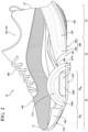
- an article of footwear 10 includes an upper 100 and sole structure 200.
- the footwear 10 may further include an anterior end 12 associated with a forward-most point of the footwear 10, and a posterior end 14 corresponding to a rearward-most point of the footwear 10.
- a longitudinal axis A 10 of the footwear 10 extends along a length of the footwear 10 from the anterior end 12 to the posterior end 14 parallel to a ground surface, and generally divides the footwear 10 into a medial side 16 and a lateral side 18. Accordingly, the medial side 16 and the lateral side 18 respectively correspond with opposite sides of the footwear 10 and extend from the anterior end 12 to the posterior end 14.
- a longitudinal direction refers to the direction extending from the anterior end 12 to the posterior end 14, while a lateral direction refers to the direction transverse to the longitudinal direction and extending from the medial side 16 to the lateral side 18.
- the article of footwear 10 may be divided into one or more regions.
- the regions may include a forefoot region 20, a mid-foot region 22, and a heel region 24.
- the forefoot region 20 may be subdivided into a toe portion 20 T corresponding with phalanges and a ball portion 20 B associated with metatarsal bones of a foot.
- the mid-foot region 22 may correspond with an arch area of the foot, and the heel region 24 may correspond with rear portions of the foot, including a calcaneus bone.
- the upper 100 includes interior surfaces that define an interior void 102 configured to receive and secure a foot for support on the sole structure 200.
- the upper 100 may be formed from one or more materials that are stitched or adhesively bonded together to form the interior void 102. Suitable materials of the upper 100 may include, but are not limited to, mesh, textiles, foam, leather, and synthetic leather. The materials may be selected and located to impart properties of durability, air-permeability, wear-resistance, flexibility, and comfort.
- the upper 100 includes a strobel having a bottom surface opposing the sole structure 200 and an opposing top surface defining a footbed of the interior void 102. Stitching or adhesives may secure the strobel to the upper 100.
- the footbed may be contoured to conform to a profile of the bottom surface (e.g., plantar) of the foot.
- the upper 100 may also incorporate additional layers such as an insole or sockliner that may be disposed upon the strobel and reside within the interior void 102 of the upper 100 to receive a plantar surface of the foot to enhance the comfort of the article of footwear 10.
- An ankle opening 104 in the heel region 24 may provide access to the interior void 102.
- the ankle opening 104 may receive a foot to secure the foot within the void 102 and to facilitate entry and removal of the foot from and to the interior void 102.
- one or more fasteners 106 extend along the upper 100 to adjust a fit of the interior void 102 around the foot and to accommodate entry and removal of the foot therefrom.
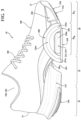
- the sole structure 200 includes a midsole 202 configured to provide characteristics of cushioning and responsiveness, and an outsole 204 configured to provide a ground-engaging surface to the article of footwear 10.
- the midsole 202 of the present example is formed as a composite structure and includes various subcomponents configured to impart desired characteristics to the article of footwear 10.
- the midsole 202 includes a rigid or semi-rigid plate 206, a forefoot cushioning element 208, a heel cushioning element 210, and a fluid cushioning arrangement 212 having one or more fluid-filled bladders 214.
- the outsole 204 includes a composite structure and includes a toe fragment 216 attached to the forefoot cushioning element 208 at the anterior end 12, a forefoot fragment 218 disposed in the forefoot region 20 and attached to the fluid cushioning arrangement 212, and a heel fragment 220 attached to the heel cushioning element 210 at the posterior end 14.
- the plate 206 includes an elastomeric material, such as a polyether block amide (PEBA) (e.g., Pebax ® brand elastomers manufactured by Arkema S. A).
- PEBA polyether block amide
- the plate 206 extends from a first end 222 disposed in the forefoot region 20 to a second end 224 disposed at the posterior end 14.
- the plate 206 includes a top surface 225a attached to the strobel of the upper 100 and bottom surface 225b formed on an opposite side of the plate 206 from the top surface 225a. A distance from the top surface 225a to the bottom surface 225b defines a thickness of the plate 206.
- the first end 222 of the plate 206 may include a forked configuration where a gap or split 226 extends through the thickness of the plate 206 and partially along a length of the plate 206 from the first end 222.
- the gap 226 separates the first end 222 into medial and lateral tabs 228a, 228b that can flex independently from each other.
- the medial and lateral tabs 228a, 228b may include sockets 229a, 229b on the bottom surface 225b for engaging and securing the bladders 214 of the fluid cushioning arrangement 212.
- the forefoot cushioning element 208 and the heel cushioning element 210 each include a resilient polymeric material, such as foam or rubber, to impart properties of cushioning, responsiveness, and energy distribution to the foot of the wearer.
- the forefoot cushioning element 208 and the heel cushioning element 210 may include the same or different materials to impart desired performance characteristics to the respective regions of the sole structure 200.
- Example resilient polymeric materials for the cushioning elements 208, 210 may include those based on foaming or molding one or more polymers, such as one or more elastomers (e.g., thermoplastic elastomers (TPE)).
- the one or more polymers may include aliphatic polymers, aromatic polymers, or mixtures of both; and may include homopolymers, copolymers (including terpolymers), or mixtures of both.
- the one or more polymers may include olefinic homopolymers, olefinic copolymers, or blends thereof.
- olefinic polymers include polyethylene, polypropylene, and combinations thereof.
- the one or more polymers may include one or more ethylene copolymers, such as, ethylene-vinyl acetate (EVA) copolymers, EVOH copolymers, ethylene-ethyl acrylate copolymers, ethylene-unsaturated mono-fatty acid copolymers, and combinations thereof.
- EVA ethylene-vinyl acetate
- the one or more polymers may include one or more polyacrylates, such as polyacrylic acid, esters of polyacrylic acid, polyacrylonitrile, polyacrylic acetate, polymethyl acrylate, polyethyl acrylate, polybutyl acrylate, polymethyl methacrylate, and polyvinyl acetate; including derivatives thereof, copolymers thereof, and any combinations thereof.
- polyacrylates such as polyacrylic acid, esters of polyacrylic acid, polyacrylonitrile, polyacrylic acetate, polymethyl acrylate, polyethyl acrylate, polybutyl acrylate, polymethyl methacrylate, and polyvinyl acetate; including derivatives thereof, copolymers thereof, and any combinations thereof.
- the one or more polymers may include one or more ionomeric polymers.
- the ionomeric polymers may include polymers with carboxylic acid functional groups, sulfonic acid functional groups, salts thereof (e.g., sodium, magnesium, potassium, etc.), and/or anhydrides thereof.
- the ionomeric polymer(s) may include one or more fatty acid-modified ionomeric polymers, polystyrene sulfonate, ethylene-methacrylic acid copolymers, and combinations thereof.
- the one or more polymers may include one or more styrenic block copolymers, such as acrylonitrile butadiene styrene block copolymers, styrene acrylonitrile block copolymers, styrene ethylene butylene styrene block copolymers, styrene ethylene butadiene styrene block copolymers, styrene ethylene propylene styrene block copolymers, styrene butadiene styrene block copolymers, and combinations thereof.
- styrenic block copolymers such as acrylonitrile butadiene styrene block copolymers, styrene acrylonitrile block copolymers, styrene ethylene butylene styrene block copolymers, styrene ethylene butadiene styrene block
- the one or more polymers may include one or more polyamide copolymers (e.g., polyamide-polyether copolymers) and/or one or more polyurethanes (e.g., crosslinked polyurethanes and/or thermoplastic polyurethanes). Examples of suitable polyurethanes include those discussed above for barrier layers.
- the one or more polymers may include one or more natural and/or synthetic rubbers, such as butadiene and isoprene.
- the foamed material may be foamed using a physical blowing agent which phase transitions to a gas based on a change in temperature and/or pressure, or a chemical blowing agent which forms a gas when heated above its activation temperature.
- the chemical blowing agent may be an azo compound such as adodicarbonamide, sodium bicarbonate, and/or an isocyanate.
- the foamed polymeric material may be a crosslinked foamed material.
- a peroxide-based crosslinking agent such as dicumyl peroxide may be used.
- the foamed polymeric material may include one or more fillers such as pigments, modified or natural clays, modified or unmodified synthetic clays, talc glass fiber, powdered glass, modified or natural silica, calcium carbonate, mica, paper, wood chips, and the like.
- the resilient polymeric material may be formed using a molding process.
- the uncured elastomer e.g., rubber
- a curing package such as a sulfur-based or peroxide-based curing package, calendared, formed into shape, placed in a mold, and vulcanized.
- the resilient polymeric material when the resilient polymeric material is a foamed material, the material may be foamed during a molding process, such as an injection molding process.
- a thermoplastic polymeric material may be melted in the barrel of an injection molding system and combined with a physical or chemical blowing agent and optionally a crosslinking agent, and then injected into a mold under conditions which activate the blowing agent, forming a molded foam.
- the foamed material when the resilient polymeric material is a foamed material, the foamed material may be a compression molded foam. Compression molding may be used to alter the physical properties (e.g., density, stiffness and/or durometer) of a foam, or to alter the physical appearance of the foam (e.g., to fuse two or more pieces of foam, to shape the foam, etc.), or both.
- Compression molding may be used to alter the physical properties (e.g., density, stiffness and/or durometer) of a foam, or to alter the physical appearance of the foam (e.g., to fuse two or more pieces of foam, to shape the foam, etc.), or both.
- the compression molding process desirably starts by forming one or more foam preforms, such as by injection molding and foaming a polymeric material, by forming foamed particles or beads, by cutting foamed sheet stock, and the like.
- the compression molded foam may then be made by placing the one or more preforms formed of foamed polymeric material(s) in a compression mold, and applying sufficient pressure to the one or more preforms to compress the one or more preforms in a closed mold.
- the mold is closed, sufficient heat and/or pressure is applied to the one or more preforms in the closed mold for a sufficient duration of time to alter the preform(s) by forming a skin on the outer surface of the compression molded foam, fuse individual foam particles to each other, permanently increase the density of the foam(s), or any combination thereof.
- the mold is opened and the molded foam article is removed from the mold.
- the forefoot cushioning element 208 extends from a first end 230 at the anterior end 12 to a second end 232 disposed in the mid-foot region 22.
- the forefoot cushioning element 208 includes a top surface 233a attached to the bottom surface 225b of the plate 206 and a bottom surface 233b disposed on the opposite side. A distance from the top surface 233a to the bottom surface 233b defines a thickness of the forefoot cushioning element 208.
- the forefoot cushioning element 208 includes one or more apertures 234a, 234b formed through the entire thickness (i.e., from the top surface 233a to the bottom surface 233b), which are configured to receive each of the bladders 214 therein. Accordingly, when the sole structure 200 is assembled, the bladders 214 of the fluid cushioning arrangement 212 will be surrounded by the forefoot cushioning element 208.
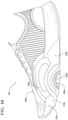
- the forefoot cushioning element 208 further includes a pair of shields 235a, 235b extending upwardly from opposite sides of the forefoot cushioning element 208 between the first end 230 and the second end 232.
- each of the shields 235a, 235b is configured to extend upwardly along one of the medial and lateral sides 16, 18 of the upper 100 in a portion of the forefoot region 20 associated with the ball of the foot, thereby providing lateral reinforcement and stability to the sides of the upper 100 in that region.
- each of the shields 235a, 235b is formed as an arched structure extending from a first end 236a, 236b to a second end 237a, 237b along the side of the forefoot cushioning element 208.
- the arched structure provides the desired lateral stability, while still allowing the sole structure 200 to flex suitably across the ball portion 20 B of the forefoot region 20.
- the shields 235a-235b define lateral openings 238a, 238b extending from an outer periphery of the forefoot cushioning element 208 and intersecting with the apertures 234 formed through the thickness of the forefoot cushioning element 208.
- the bladders 214 may be exposed through the openings 238a, 238b formed through the forefoot cushioning element 208.
- the heel cushioning element 210 is attached to a bottom surface of the plate 206 and extends from a first end 239 in the mid-foot region 22 to a second end 240 at the posterior end 14 of the sole structure 200.
- the first end 239 of the heel cushioning element 210 faces or opposes the second end 232 of the forefoot cushioning element 208.
- the first end 239 of the heel cushioning element 210 is separated from the second end 232 of the forefoot cushioning element 208 by a gap 242 in the mid-foot region 22.
- a bottom surface of the plate 206 is exposed along the gap 242.
- the gap provides stability in movements commonly associated with HIIT training exercises, such as plank positions, and allows the foot to bend naturally when driving into mountain climbers.
- the first end 239 of the heel cushioning element 210 may include a notch 244 extending along a longitudinal direction of the article of footwear 10, such that the first end 239 is separated into medial and lateral fingers 246a, 246b that can move independently of each other.
- the fluid cushioning arrangement 212 of the illustrated example includes a pair of bladders 214 each defining a respective chamber for including a pressurized fluid.
- a first one of the bladders 214 is disposed on the medial side 16 of the sole structure 200 in the forefoot region 20, and a second one of the bladders 214 is disposed on the lateral side 18 of the sole structure 200 in the forefoot region 20.
- each of the bladders 214 extends through one of the apertures 234 formed through the forefoot cushioning element 208 such that a top surface of each bladder 214 is received within one of the sockets 229a, 229b and attached to the bottom surface 225b of the plate 206, and a bottom surface of each bladder 214 is received by a socket the forefoot fragment 218 of the outsole 204.
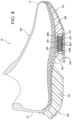
- Each of the bladders 214 may include a first barrier element 248a and a second barrier element 248b formed of an elastomeric material.
- the chamber of each of the bladders 214 may receive a tensile element 250 ( FIG. 8 ) therein.
- Each tensile element 250 may include a series of tensile strands 252 extending between an upper tensile sheet 254 and a lower tensile sheet 254.
- the upper tensile sheet 254 may be attached to the first barrier element 248a while the lower tensile sheet 254 may be attached to the second barrier element 248b. In this manner, when the bladder 214 receives the pressurized fluid, the tensile strands 252 of the tensile element 250 are placed in tension.
- the tensile strands 252 retain a desired shape of the bladder 214 when the pressurized fluid is injected into the chamber.
- the toe fragment 216 of the outsole 204 is formed of a resilient elastomeric material, and is disposed at the anterior end 12 of the sole structure 200.
- the forefoot fragment 218 is disposed in the forefoot region 20 and is formed independently of each of the toe fragment 216 and the heel fragment 220.
- the forefoot fragment 218 includes one or more sockets 256a, 256b formed in a top surface, which are configured to receive and secure a lower portion of corresponding ones of the bladders 214.
- the forefoot fragment 218 provides a bottom structure for securing the bladders 214.
- the forefoot fragment 218 may be formed of a material having a greater rigidity than the other fragments 216, 220 to impart stability between the independent bladders 214.
- the heel fragment 220 extends around the heel region 24 and includes a first segment 258a extending along the medial side 16, a second segment 258b extending along the lateral side 18, and an arcuate third segment 258c extending around the posterior end 14. As shown, the second segment 258b may be longer than the first segment 258a.
- an article of footwear 10a is provided and includes an upper 100a a sole structure 200a attached to the upper 100a.
- like reference numerals are used hereinafter and in the drawings to identify like components while like reference numerals containing letter extensions are used to identify those components that have been modified.
- the sole structure 200a includes a unitary midsole 202a including a single cushioning element including a foam material extending from the anterior end 12 to the posterior end 14.
- sole structure 200a does not include independent cushioning elements or bladders.
- the midsole 202a includes medial and lateral side shields 235c, 235d having a narrower profile than the side shields 235a, 235b of the previous example.
- the side shields 235c, 235d are formed as solid (i.e., not including openings) elements along the sides of the midsole 202a.
- the midsole 202a may include arcuate relief channels 270a-270d formed in the peripheral surface of the midsole 202a on opposite ends of the side shields 235c, 235d to allow the midsole 202a to bend about the side shields 235c, 235d.
- the sole structure 200a is configured as a simplified, lightweight alternative to the sole structure 200.
- the minimalistic sole structure 200a may be desirable for travel (i.e., packing in luggage) and for use in confined areas.
- the upper 100a of the article of footwear 10a may include arcuate flex zones 130a, 130b partially surrounding the side shields 235c, 235d. As shown, the flex zones 130a, 130b each extend from a first one of the relief channels 130a, 130c at an anterior end of one of the side shields 235c, 235d to a second one of the relief channels 130b, 130d formed at an anterior end of the respective side shield 235c, 235d. Thus, the upper 100a cooperates with the relief channels 170a-170d to provide flexibility along the metatarsophalangeal (MTP) joint.
- MTP metatarsophalangeal
- an article of footwear 10b is provided and includes an upper 100b and a sole structure 200b attached to the upper 100b.
- like reference numerals are used hereinafter and in the drawings to identify like components while like reference numerals containing letter extensions are used to identify those components that have been modified.
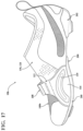
- the upper 100b includes a translucent mesh material extending over the forefoot region 20 and along the lateral side 18 along the mid-foot region 22.
- the upper 100b further includes a forefoot strap 108 and a mid-foot strap 110 each extending over the upper 100b from the medial side 16 to the lateral side 18.
- the forefoot strap 108 includes a medial forefoot band 112 attached at a biteline formed between the upper 100b and the sole structure 200b on the medial side 16 and a lateral forefoot band 114 attached at the biteline on the lateral side 18.
- Each of the forefoot bands 112, 114 includes a fixed end 116, 118 attached at the biteline and a free end operable to adjustably attach to the free end of the other forefoot band 112, 114.
- the fixed ends 116, 118 of the forefoot bands 112, 114 are flared (i.e., increase in width along a direction towards the biteline) and include an arcuate reinforcement strip 120 attached to or embedded within the fixed end 116, 118.
- the fixed ends 116, 118 of the forefoot strap 108 may function similar to the shields 235a, 235b discussed above to provide lateral stability along the ball region of the foot while also allowing the upper to flex or bend along the metatarsophalangeal (MTP) joint.
- MTP metatarsophalangeal
- the mid-foot strap 110 includes a medial mid-foot band 122 and a lateral mid-foot band 124 cooperating to extend over the upper 100b adjacent to the ankle opening 104.
- the medial mid-foot band 122 is integrally formed with the upper 100b, as shown in FIGS. 17 and 19 .
- medial mid-foot band 122 extends along the medial side of the footwear and defines a medial quarter panel and a medial heel panel.
- the medial mid-foot band 122 can be drawn over an instep region of the foot to adjust a size of the upper 100b and the ankle opening 104.
- the lateral mid-foot band 124 includes a fixed end 126 attached to the upper 100b on a lateral side 18 of the ankle opening 104 and a second end configured to adjustably attach to the medial mid-foot band 122.
- the sole structure 200b includes a forefoot plate 260 and a heel plate 262 attached to the upper 100b.
- the forefoot plate 260 includes a coupler 264 with SPD and Delta cleats.
- the forefoot plate 260 also includes a plurality of vents 266 formed through a thickness of the forefoot plate 260 and in communication with the interior void 102 of the upper 100 to provide ventilation to the plantar surface of the foot within the upper 100b.
- Each of the forefoot plate 260 and the heel plate 262 includes resilient studs 268 to provide traction during walking.
- fluid-filled bladders with tensile members in the forefoot not only creates a dynamic aesthetic, but also helps provide impact protection and responsiveness.
- the fluid-filled cushioning arrangement - a two-unit system under the forefoot - does not act alone.
- a plate running from the heel to the forefoot helps roll the foot forward and into a ready position for the majority of upright HIIT movements.
- the upper is crafted to support lateral moves, such as skaters and side lunges.
- An article of footwear comprising: an upper; a plate having a top surface facing the upper and a bottom surface formed on an opposite side than the top surface, the plate extending from a first end in a forefoot region to a second end in a heel region; a first cushioning element having an upper surface attached to the bottom surface of the plate in the forefoot region and including a first side shield extending from the upper surface and along a medial side of the upper and a second side shield extending from the upper surface and along a lateral side of the upper; and one or more fluid-filled bladders each at least partially surrounded by the first cushioning element in the forefoot region and having a top surface attached to the bottom surface of the plate.
- Clause 2 The article of footwear of Clause 1, wherein the one or more fluid-filled bladders includes a first fluid-filled bladder disposed on a medial side and a second fluid-filled bladder disposed on a lateral side.
- Clause 3 The article of footwear of any of the preceding Clauses, wherein the first end of the plate includes a lateral portion and a medial portion separated from the lateral portion by a gap.
- Clause 4 The article of footwear of any of the preceding Clauses, wherein the first cushioning element includes one or more apertures each configured to receive a corresponding one of the one or more fluid-filled bladders.
- Clause 5 The article of footwear of any of the preceding Clauses, wherein each of the plate and the upper are received between the first side shield and the second side shield.
- Clause 6 The article of footwear of any of the preceding Clauses, wherein the one or more fluid-filled bladders is disposed between the first side shield and the second side shield.
- Clause 7 The article of footwear of any of the preceding Clauses, wherein each of the first side shield and the second side shield includes an arch extending from a first end to a second end along the respective side of the article of footwear.
- Clause 8 The article of footwear of any of the preceding Clauses, wherein further comprising a second cushioning element disposed in the heel region and spaced apart from the first cushioning element by a gap in a mid-foot region of the article of footwear.
- Clause 9 The article of footwear of Clause 8, further comprising an outsole having a first fragment attached to the first cushioning element, a second fragment attached to the second cushioning element, and a third fragment attached to the one or more fluid-filled bladders.
- Clause 10 The article of footwear of Clause 9, wherein the plate includes one or more upper sockets each receiving a first end of one of the one or more bladders and the outsole includes one or more lower sockets each receiving a second end of one of the one or more bladders.
- An article of footwear comprising: an upper; a plate having a top surface facing the upper and a bottom surface formed on an opposite side than the top surface, the plate extending from a first end in a forefoot region to a second end in a heel region; a first cushioning element having an upper surface attached to the bottom surface of the plate in the forefoot region and including a first side shield defining a first opening formed in a lateral side of the first cushioning element and a second side shield defining a second opening formed in a medial side of the first cushioning element; and one or more fluid-filled bladders each at least partially surrounded by the first cushioning element in the forefoot region and having a top surface attached to the bottom surface of the plate.
- Clause 12 The article of footwear of Clause 11, wherein the one or more fluid-filled bladders includes a first fluid-filled bladder disposed on a medial side and a second fluid-filled bladder disposed on a lateral side.
- Clause 13 The article of footwear of any of the preceding Clauses, wherein the first end of the plate includes a lateral portion and a medial portion separated from the lateral portion by a gap.
- Clause 14 The article of footwear of any of the preceding Clauses, wherein the first cushioning element includes one or more apertures each configured to receive a corresponding one of the one or more fluid-filled bladders.
- Clause 15 The article of footwear of any of the preceding Clauses, wherein each of the plate and the upper are received between the first side shield and the second side shield.
- Clause 16 The article of footwear of any of the preceding Clauses, wherein the one or more fluid-filled bladders is disposed between the first side shield and the second side shield.
- Clause 17 The article of footwear of any of the preceding Clauses, wherein each of the first side shield and the second side shield includes an arch extending from a first end to a second end along the respective side of the article of footwear.
- Clause 18 The article of footwear of any of the preceding Clauses, wherein further comprising a second cushioning element disposed in the heel region and spaced apart from the first cushioning element by a gap in a mid-foot region of the article of footwear.
- Clause 19 The article of footwear of Clause 18, further comprising an outsole having a first fragment attached to the first cushioning element, a second fragment attached to the second cushioning element, and a third fragment attached to the one or more fluid-filled bladders.
- Clause 20 The article of footwear of Clause 19, wherein the plate includes one or more upper sockets each receiving a first end of one of the one or more bladders and the outsole includes one or more lower sockets each receiving a second end of one of the one or more bladders.
Landscapes
- Chemical & Material Sciences (AREA)
- Engineering & Computer Science (AREA)
- Materials Engineering (AREA)
- Health & Medical Sciences (AREA)
- Epidemiology (AREA)
- General Health & Medical Sciences (AREA)
- Public Health (AREA)
- Footwear And Its Accessory, Manufacturing Method And Apparatuses (AREA)
Priority Applications (1)
| Application Number | Priority Date | Filing Date | Title |
|---|---|---|---|
| EP24213667.9A EP4487728B1 (de) | 2019-12-09 | 2020-12-09 | Fussbekleidungsartikel |
Applications Claiming Priority (4)
| Application Number | Priority Date | Filing Date | Title |
|---|---|---|---|
| US201962945826P | 2019-12-09 | 2019-12-09 | |
| US17/115,768 US11737509B2 (en) | 2019-12-09 | 2020-12-08 | Article of footwear |
| PCT/US2020/063916 WO2021119070A1 (en) | 2019-12-09 | 2020-12-09 | Article of footwear |
| EP20834084.4A EP4072369B1 (de) | 2019-12-09 | 2020-12-09 | Schuhartikel |
Related Parent Applications (2)
| Application Number | Title | Priority Date | Filing Date |
|---|---|---|---|
| EP20834084.4A Division-Into EP4072369B1 (de) | 2019-12-09 | 2020-12-09 | Schuhartikel |
| EP20834084.4A Division EP4072369B1 (de) | 2019-12-09 | 2020-12-09 | Schuhartikel |
Related Child Applications (1)
| Application Number | Title | Priority Date | Filing Date |
|---|---|---|---|
| EP24213667.9A Division EP4487728B1 (de) | 2019-12-09 | 2020-12-09 | Fussbekleidungsartikel |
Publications (2)
| Publication Number | Publication Date |
|---|---|
| EP4215076A1 true EP4215076A1 (de) | 2023-07-26 |
| EP4215076B1 EP4215076B1 (de) | 2024-11-27 |
Family
ID=76208907
Family Applications (3)
| Application Number | Title | Priority Date | Filing Date |
|---|---|---|---|
| EP23161021.3A Active EP4215076B1 (de) | 2019-12-09 | 2020-12-09 | Schuhwerk |
| EP24213667.9A Active EP4487728B1 (de) | 2019-12-09 | 2020-12-09 | Fussbekleidungsartikel |
| EP20834084.4A Active EP4072369B1 (de) | 2019-12-09 | 2020-12-09 | Schuhartikel |
Family Applications After (2)
| Application Number | Title | Priority Date | Filing Date |
|---|---|---|---|
| EP24213667.9A Active EP4487728B1 (de) | 2019-12-09 | 2020-12-09 | Fussbekleidungsartikel |
| EP20834084.4A Active EP4072369B1 (de) | 2019-12-09 | 2020-12-09 | Schuhartikel |
Country Status (6)
| Country | Link |
|---|---|
| US (2) | US11737509B2 (de) |
| EP (3) | EP4215076B1 (de) |
| JP (1) | JP7761275B2 (de) |
| KR (1) | KR102756331B1 (de) |
| CN (2) | CN120304613A (de) |
| WO (1) | WO2021119070A1 (de) |
Families Citing this family (32)
| Publication number | Priority date | Publication date | Assignee | Title |
|---|---|---|---|---|
| USD878026S1 (en) * | 2018-03-19 | 2020-03-17 | Reebok International Limited | Shoe |
| NL2023135B1 (en) * | 2019-05-15 | 2020-12-01 | Anbo Amersfoort B V | Shoe sole assembly, shoe, and method of manufacturing a shoe |
| USD943935S1 (en) * | 2020-06-26 | 2022-02-22 | Nike, Inc. | Shoe |
| US11633010B2 (en) * | 2020-07-22 | 2023-04-25 | Nike, Inc. | Sole structure for article of footwear and article of footwear |
| USD932158S1 (en) * | 2020-10-29 | 2021-10-05 | Nike, Inc. | Shoe |
| USD935149S1 (en) * | 2020-12-22 | 2021-11-09 | Nike, Inc. | Shoe |
| USD935148S1 (en) * | 2020-12-22 | 2021-11-09 | Nike, Inc. | Shoe |
| USD943260S1 (en) * | 2021-03-03 | 2022-02-15 | Nike, Inc. | Shoe |
| USD945756S1 (en) * | 2021-04-14 | 2022-03-15 | Nike, Inc. | Shoe |
| USD930962S1 (en) * | 2021-04-23 | 2021-09-21 | Qiwei Luo | Shoe with replaceable sole |
| USD951614S1 (en) * | 2021-06-09 | 2022-05-17 | Nike, Inc. | Shoe |
| USD950908S1 (en) * | 2021-06-09 | 2022-05-10 | Nike, Inc. | Shoe |
| USD950215S1 (en) * | 2021-06-09 | 2022-05-03 | Nike, Inc. | Shoe |
| USD968770S1 (en) * | 2021-06-09 | 2022-11-08 | Nike, Inc. | Shoe |
| US20220395056A1 (en) * | 2021-06-11 | 2022-12-15 | Nike, Inc. | Sole structure for article of footwear |
| EP4351375B1 (de) * | 2021-06-11 | 2025-12-17 | Nike Innovate C.V. | Sohlenstruktur für schuhwerk |
| USD949534S1 (en) * | 2021-06-17 | 2022-04-26 | Nike, Inc. | Shoe |
| USD992882S1 (en) * | 2021-07-02 | 2023-07-25 | Nike, Inc. | Shoe |
| USD972822S1 (en) * | 2021-09-30 | 2022-12-20 | Nike, Inc. | Shoe |
| USD976550S1 (en) | 2021-09-30 | 2023-01-31 | Nike, Inc. | Shoe |
| USD972820S1 (en) * | 2021-09-30 | 2022-12-20 | Nike, Inc. | Shoe |
| IT202100028415A1 (it) * | 2021-11-09 | 2023-05-09 | La Sportiva S P A | Procedimento per la produzione di una calzatura. |
| USD1102101S1 (en) * | 2022-06-14 | 2025-11-18 | Nike, Inc. | Shoe |
| USD998305S1 (en) | 2022-12-02 | 2023-09-12 | Nike, Inc. | Shoe |
| USD1084624S1 (en) * | 2023-06-01 | 2025-07-22 | Caleres, Inc. | Shoe sole |
| USD1017992S1 (en) * | 2023-07-28 | 2024-03-19 | Nike, Inc. | Shoe |
| USD1017991S1 (en) * | 2023-07-28 | 2024-03-19 | Nike, Inc. | Shoe |
| USD1018006S1 (en) * | 2023-07-28 | 2024-03-19 | Nike, Inc. | Shoe |
| USD1017994S1 (en) * | 2023-07-28 | 2024-03-19 | Nike, Inc. | Shoe |
| USD1017993S1 (en) * | 2023-07-28 | 2024-03-19 | Nike, Inc. | Shoe |
| US12569031B2 (en) | 2024-04-10 | 2026-03-10 | Puma SE | Sole structure for an article of footwear |
| US12593893B2 (en) * | 2024-08-05 | 2026-04-07 | Nike, Inc. | Athletic systems |
Citations (1)
| Publication number | Priority date | Publication date | Assignee | Title |
|---|---|---|---|---|
| US20190320759A1 (en) * | 2018-04-20 | 2019-10-24 | Nike, Inc. | Sole structure with plates and intervening fluid-filled bladder and method of manufacturing |
Family Cites Families (11)
| Publication number | Priority date | Publication date | Assignee | Title |
|---|---|---|---|---|
| US6453577B1 (en) * | 1996-02-09 | 2002-09-24 | Reebok International Ltd. | Support and cushioning system for an article of footwear |
| US6009637A (en) * | 1998-03-02 | 2000-01-04 | Pavone; Luigi Alessio | Helium footwear sole |
| JP3497418B2 (ja) | 1999-07-21 | 2004-02-16 | 株式会社アシックス | ミッドソールの補強構造 |
| US7334351B2 (en) * | 2004-06-07 | 2008-02-26 | Energy Management Athletics, Llc | Shoe apparatus with improved efficiency |
| US20070220778A1 (en) * | 2006-03-21 | 2007-09-27 | Nike Inc. | Article of footwear with a lightweight foam midsole |
| US10856612B2 (en) | 2012-09-20 | 2020-12-08 | Nike, Inc. | Sole structures and articles of footwear having plate moderated fluid-filled bladders and/or foam type impact force attenuation members |
| US10251445B2 (en) * | 2015-05-08 | 2019-04-09 | Under Armour, Inc. | Article of footwear with improved arch support |
| KR102207241B1 (ko) * | 2017-02-01 | 2021-01-22 | 나이키 이노베이트 씨.브이. | 밑창 구조체를 위한 적층형 완충 장치 |
| JP7430530B2 (ja) | 2017-03-16 | 2024-02-13 | ナイキ イノベイト シーブイ | 履物の物品のための緩衝部材 |
| US11633010B2 (en) * | 2020-07-22 | 2023-04-25 | Nike, Inc. | Sole structure for article of footwear and article of footwear |
| US12250986B2 (en) * | 2022-02-25 | 2025-03-18 | Nike, Inc. | Article of footwear |
-
2020
- 2020-12-08 US US17/115,768 patent/US11737509B2/en active Active
- 2020-12-09 EP EP23161021.3A patent/EP4215076B1/de active Active
- 2020-12-09 KR KR1020227021265A patent/KR102756331B1/ko active Active
- 2020-12-09 WO PCT/US2020/063916 patent/WO2021119070A1/en not_active Ceased
- 2020-12-09 CN CN202510383664.9A patent/CN120304613A/zh active Pending
- 2020-12-09 CN CN202080092675.7A patent/CN114929059B/zh active Active
- 2020-12-09 EP EP24213667.9A patent/EP4487728B1/de active Active
- 2020-12-09 EP EP20834084.4A patent/EP4072369B1/de active Active
- 2020-12-09 JP JP2022534355A patent/JP7761275B2/ja active Active
-
2023
- 2023-07-14 US US18/352,502 patent/US12532939B2/en active Active
Patent Citations (1)
| Publication number | Priority date | Publication date | Assignee | Title |
|---|---|---|---|---|
| US20190320759A1 (en) * | 2018-04-20 | 2019-10-24 | Nike, Inc. | Sole structure with plates and intervening fluid-filled bladder and method of manufacturing |
Also Published As
| Publication number | Publication date |
|---|---|
| CN114929059B (zh) | 2025-04-15 |
| EP4487728B1 (de) | 2026-04-22 |
| US20210169170A1 (en) | 2021-06-10 |
| KR20220099574A (ko) | 2022-07-13 |
| US12532939B2 (en) | 2026-01-27 |
| CN114929059A (zh) | 2022-08-19 |
| JP7761275B2 (ja) | 2025-10-28 |
| US20230354955A1 (en) | 2023-11-09 |
| EP4072369B1 (de) | 2023-09-27 |
| WO2021119070A1 (en) | 2021-06-17 |
| EP4072369A1 (de) | 2022-10-19 |
| US11737509B2 (en) | 2023-08-29 |
| EP4215076B1 (de) | 2024-11-27 |
| EP4487728A2 (de) | 2025-01-08 |
| CN120304613A (zh) | 2025-07-15 |
| JP2023504288A (ja) | 2023-02-02 |
| KR102756331B1 (ko) | 2025-01-16 |
| EP4487728A3 (de) | 2025-04-09 |
Similar Documents
| Publication | Publication Date | Title |
|---|---|---|
| EP4215076B1 (de) | Schuhwerk | |
| US12239183B2 (en) | Article of footwear | |
| US12225975B2 (en) | Article of footwear with heel structure | |
| US11758981B2 (en) | Tensioning system for article of footwear | |
| US12426668B2 (en) | Article of footwear | |
| US11766092B2 (en) | Sole structure for article of footwear | |
| US11399590B2 (en) | Sole structure for article of footwear | |
| US12419385B2 (en) | Article of footwear including an integrated stability member | |
| HK40098357A (en) | Article of footwear | |
| HK40098357B (en) | Article of footwear | |
| HK40079240A (en) | Article of footwear | |
| US20260096626A1 (en) | Sole structure for article of footwear | |
| HK40079240B (zh) | 鞋类物品 | |
| WO2026076389A1 (en) | Sole structure for article of footwear | |
| CN118613187A (zh) | 具有足跟结构的鞋类制品 | |
| HK40071677A (en) | Article of footwear |
Legal Events
| Date | Code | Title | Description |
|---|---|---|---|
| PUAI | Public reference made under article 153(3) epc to a published international application that has entered the european phase |
Free format text: ORIGINAL CODE: 0009012 |
|
| STAA | Information on the status of an ep patent application or granted ep patent |
Free format text: STATUS: THE APPLICATION HAS BEEN PUBLISHED |
|
| AC | Divisional application: reference to earlier application |
Ref document number: 4072369 Country of ref document: EP Kind code of ref document: P |
|
| AK | Designated contracting states |
Kind code of ref document: A1 Designated state(s): AL AT BE BG CH CY CZ DE DK EE ES FI FR GB GR HR HU IE IS IT LI LT LU LV MC MK MT NL NO PL PT RO RS SE SI SK SM TR |
|
| STAA | Information on the status of an ep patent application or granted ep patent |
Free format text: STATUS: REQUEST FOR EXAMINATION WAS MADE |
|
| 17P | Request for examination filed |
Effective date: 20240125 |
|
| RBV | Designated contracting states (corrected) |
Designated state(s): AL AT BE BG CH CY CZ DE DK EE ES FI FR GB GR HR HU IE IS IT LI LT LU LV MC MK MT NL NO PL PT RO RS SE SI SK SM TR |
|
| REG | Reference to a national code |
Ref country code: HK Ref legal event code: DE Ref document number: 40098357 Country of ref document: HK |
|
| GRAP | Despatch of communication of intention to grant a patent |
Free format text: ORIGINAL CODE: EPIDOSNIGR1 |
|
| STAA | Information on the status of an ep patent application or granted ep patent |
Free format text: STATUS: GRANT OF PATENT IS INTENDED |
|
| P01 | Opt-out of the competence of the unified patent court (upc) registered |
Effective date: 20240522 |
|
| INTG | Intention to grant announced |
Effective date: 20240619 |
|
| RIN1 | Information on inventor provided before grant (corrected) |
Inventor name: POLLOCK, STUART D. Inventor name: SCOTT, CHLOE Inventor name: LUPINEK, JAROSLAV J. Inventor name: KUANG-NAN, LIAO Inventor name: HONG, JIN Inventor name: GLEASON, ERIN Inventor name: FAHMI, WINDRA |
|
| GRAS | Grant fee paid |
Free format text: ORIGINAL CODE: EPIDOSNIGR3 |
|
| GRAA | (expected) grant |
Free format text: ORIGINAL CODE: 0009210 |
|
| STAA | Information on the status of an ep patent application or granted ep patent |
Free format text: STATUS: THE PATENT HAS BEEN GRANTED |
|
| AC | Divisional application: reference to earlier application |
Ref document number: 4072369 Country of ref document: EP Kind code of ref document: P |
|
| AK | Designated contracting states |
Kind code of ref document: B1 Designated state(s): AL AT BE BG CH CY CZ DE DK EE ES FI FR GB GR HR HU IE IS IT LI LT LU LV MC MK MT NL NO PL PT RO RS SE SI SK SM TR |
|
| REG | Reference to a national code |
Ref country code: GB Ref legal event code: FG4D |
|
| REG | Reference to a national code |
Ref country code: CH Ref legal event code: EP |
|
| REG | Reference to a national code |
Ref country code: DE Ref legal event code: R096 Ref document number: 602020042333 Country of ref document: DE |
|
| REG | Reference to a national code |
Ref country code: IE Ref legal event code: FG4D |
|
| REG | Reference to a national code |
Ref country code: LT Ref legal event code: MG9D |
|
| REG | Reference to a national code |
Ref country code: NL Ref legal event code: MP Effective date: 20241127 |
|
| PG25 | Lapsed in a contracting state [announced via postgrant information from national office to epo] |
Ref country code: IS Free format text: LAPSE BECAUSE OF FAILURE TO SUBMIT A TRANSLATION OF THE DESCRIPTION OR TO PAY THE FEE WITHIN THE PRESCRIBED TIME-LIMIT Effective date: 20250327 Ref country code: HR Free format text: LAPSE BECAUSE OF FAILURE TO SUBMIT A TRANSLATION OF THE DESCRIPTION OR TO PAY THE FEE WITHIN THE PRESCRIBED TIME-LIMIT Effective date: 20241127 Ref country code: PT Free format text: LAPSE BECAUSE OF FAILURE TO SUBMIT A TRANSLATION OF THE DESCRIPTION OR TO PAY THE FEE WITHIN THE PRESCRIBED TIME-LIMIT Effective date: 20250327 |
|
| PG25 | Lapsed in a contracting state [announced via postgrant information from national office to epo] |
Ref country code: FI Free format text: LAPSE BECAUSE OF FAILURE TO SUBMIT A TRANSLATION OF THE DESCRIPTION OR TO PAY THE FEE WITHIN THE PRESCRIBED TIME-LIMIT Effective date: 20241127 Ref country code: NL Free format text: LAPSE BECAUSE OF FAILURE TO SUBMIT A TRANSLATION OF THE DESCRIPTION OR TO PAY THE FEE WITHIN THE PRESCRIBED TIME-LIMIT Effective date: 20241127 |
|
| REG | Reference to a national code |
Ref country code: AT Ref legal event code: MK05 Ref document number: 1744808 Country of ref document: AT Kind code of ref document: T Effective date: 20241127 |
|
| PG25 | Lapsed in a contracting state [announced via postgrant information from national office to epo] |
Ref country code: BG Free format text: LAPSE BECAUSE OF FAILURE TO SUBMIT A TRANSLATION OF THE DESCRIPTION OR TO PAY THE FEE WITHIN THE PRESCRIBED TIME-LIMIT Effective date: 20241127 |
|
| PG25 | Lapsed in a contracting state [announced via postgrant information from national office to epo] |
Ref country code: ES Free format text: LAPSE BECAUSE OF FAILURE TO SUBMIT A TRANSLATION OF THE DESCRIPTION OR TO PAY THE FEE WITHIN THE PRESCRIBED TIME-LIMIT Effective date: 20241127 |
|
| PG25 | Lapsed in a contracting state [announced via postgrant information from national office to epo] |
Ref country code: NO Free format text: LAPSE BECAUSE OF FAILURE TO SUBMIT A TRANSLATION OF THE DESCRIPTION OR TO PAY THE FEE WITHIN THE PRESCRIBED TIME-LIMIT Effective date: 20250227 |
|
| PG25 | Lapsed in a contracting state [announced via postgrant information from national office to epo] |
Ref country code: GR Free format text: LAPSE BECAUSE OF FAILURE TO SUBMIT A TRANSLATION OF THE DESCRIPTION OR TO PAY THE FEE WITHIN THE PRESCRIBED TIME-LIMIT Effective date: 20250228 Ref country code: LV Free format text: LAPSE BECAUSE OF FAILURE TO SUBMIT A TRANSLATION OF THE DESCRIPTION OR TO PAY THE FEE WITHIN THE PRESCRIBED TIME-LIMIT Effective date: 20241127 Ref country code: AT Free format text: LAPSE BECAUSE OF FAILURE TO SUBMIT A TRANSLATION OF THE DESCRIPTION OR TO PAY THE FEE WITHIN THE PRESCRIBED TIME-LIMIT Effective date: 20241127 |
|
| PG25 | Lapsed in a contracting state [announced via postgrant information from national office to epo] |
Ref country code: PL Free format text: LAPSE BECAUSE OF FAILURE TO SUBMIT A TRANSLATION OF THE DESCRIPTION OR TO PAY THE FEE WITHIN THE PRESCRIBED TIME-LIMIT Effective date: 20241127 |
|
| PG25 | Lapsed in a contracting state [announced via postgrant information from national office to epo] |
Ref country code: RS Free format text: LAPSE BECAUSE OF FAILURE TO SUBMIT A TRANSLATION OF THE DESCRIPTION OR TO PAY THE FEE WITHIN THE PRESCRIBED TIME-LIMIT Effective date: 20250227 |
|
| PG25 | Lapsed in a contracting state [announced via postgrant information from national office to epo] |
Ref country code: SM Free format text: LAPSE BECAUSE OF FAILURE TO SUBMIT A TRANSLATION OF THE DESCRIPTION OR TO PAY THE FEE WITHIN THE PRESCRIBED TIME-LIMIT Effective date: 20241127 |
|
| PG25 | Lapsed in a contracting state [announced via postgrant information from national office to epo] |
Ref country code: DK Free format text: LAPSE BECAUSE OF FAILURE TO SUBMIT A TRANSLATION OF THE DESCRIPTION OR TO PAY THE FEE WITHIN THE PRESCRIBED TIME-LIMIT Effective date: 20241127 |
|
| PG25 | Lapsed in a contracting state [announced via postgrant information from national office to epo] |
Ref country code: EE Free format text: LAPSE BECAUSE OF FAILURE TO SUBMIT A TRANSLATION OF THE DESCRIPTION OR TO PAY THE FEE WITHIN THE PRESCRIBED TIME-LIMIT Effective date: 20241127 |
|
| PG25 | Lapsed in a contracting state [announced via postgrant information from national office to epo] |
Ref country code: RO Free format text: LAPSE BECAUSE OF FAILURE TO SUBMIT A TRANSLATION OF THE DESCRIPTION OR TO PAY THE FEE WITHIN THE PRESCRIBED TIME-LIMIT Effective date: 20241127 |
|
| PG25 | Lapsed in a contracting state [announced via postgrant information from national office to epo] |
Ref country code: SK Free format text: LAPSE BECAUSE OF FAILURE TO SUBMIT A TRANSLATION OF THE DESCRIPTION OR TO PAY THE FEE WITHIN THE PRESCRIBED TIME-LIMIT Effective date: 20241127 |
|
| PG25 | Lapsed in a contracting state [announced via postgrant information from national office to epo] |
Ref country code: CZ Free format text: LAPSE BECAUSE OF FAILURE TO SUBMIT A TRANSLATION OF THE DESCRIPTION OR TO PAY THE FEE WITHIN THE PRESCRIBED TIME-LIMIT Effective date: 20241127 |
|
| PG25 | Lapsed in a contracting state [announced via postgrant information from national office to epo] |
Ref country code: IT Free format text: LAPSE BECAUSE OF FAILURE TO SUBMIT A TRANSLATION OF THE DESCRIPTION OR TO PAY THE FEE WITHIN THE PRESCRIBED TIME-LIMIT Effective date: 20241127 |
|
| REG | Reference to a national code |
Ref country code: CH Ref legal event code: PL |
|
| PG25 | Lapsed in a contracting state [announced via postgrant information from national office to epo] |
Ref country code: LU Free format text: LAPSE BECAUSE OF NON-PAYMENT OF DUE FEES Effective date: 20241209 |
|
| REG | Reference to a national code |
Ref country code: DE Ref legal event code: R097 Ref document number: 602020042333 Country of ref document: DE |
|
| PG25 | Lapsed in a contracting state [announced via postgrant information from national office to epo] |
Ref country code: SE Free format text: LAPSE BECAUSE OF FAILURE TO SUBMIT A TRANSLATION OF THE DESCRIPTION OR TO PAY THE FEE WITHIN THE PRESCRIBED TIME-LIMIT Effective date: 20241127 |
|
| PG25 | Lapsed in a contracting state [announced via postgrant information from national office to epo] |
Ref country code: MC Free format text: LAPSE BECAUSE OF FAILURE TO SUBMIT A TRANSLATION OF THE DESCRIPTION OR TO PAY THE FEE WITHIN THE PRESCRIBED TIME-LIMIT Effective date: 20241127 |
|
| PLBE | No opposition filed within time limit |
Free format text: ORIGINAL CODE: 0009261 |
|
| STAA | Information on the status of an ep patent application or granted ep patent |
Free format text: STATUS: NO OPPOSITION FILED WITHIN TIME LIMIT |
|
| REG | Reference to a national code |
Ref country code: BE Ref legal event code: MM Effective date: 20241231 |
|
| PG25 | Lapsed in a contracting state [announced via postgrant information from national office to epo] |
Ref country code: BE Free format text: LAPSE BECAUSE OF NON-PAYMENT OF DUE FEES Effective date: 20241231 |
|
| PGFP | Annual fee paid to national office [announced via postgrant information from national office to epo] |
Ref country code: FR Payment date: 20250930 Year of fee payment: 6 |
|
| PG25 | Lapsed in a contracting state [announced via postgrant information from national office to epo] |
Ref country code: CH Free format text: LAPSE BECAUSE OF NON-PAYMENT OF DUE FEES Effective date: 20241231 |
|
| PG25 | Lapsed in a contracting state [announced via postgrant information from national office to epo] |
Ref country code: IE Free format text: LAPSE BECAUSE OF NON-PAYMENT OF DUE FEES Effective date: 20241209 |
|
| 26N | No opposition filed |
Effective date: 20250828 |
|
| PGFP | Annual fee paid to national office [announced via postgrant information from national office to epo] |
Ref country code: DE Payment date: 20250930 Year of fee payment: 6 |
|
| PGFP | Annual fee paid to national office [announced via postgrant information from national office to epo] |
Ref country code: GB Payment date: 20251001 Year of fee payment: 6 |