EP4213352A1 - Linear driver for electric furniture, and electric furniture - Google Patents
Linear driver for electric furniture, and electric furniture Download PDFInfo
- Publication number
- EP4213352A1 EP4213352A1 EP21908241.9A EP21908241A EP4213352A1 EP 4213352 A1 EP4213352 A1 EP 4213352A1 EP 21908241 A EP21908241 A EP 21908241A EP 4213352 A1 EP4213352 A1 EP 4213352A1
- Authority
- EP
- European Patent Office
- Prior art keywords
- housing
- worm wheel
- lead screw
- electric furniture
- linear driver
- Prior art date
- Legal status (The legal status is an assumption and is not a legal conclusion. Google has not performed a legal analysis and makes no representation as to the accuracy of the status listed.)
- Pending
Links
- 239000010687 lubricating oil Substances 0.000 description 4
- 239000000463 material Substances 0.000 description 2
- 230000002093 peripheral effect Effects 0.000 description 2
- 230000005489 elastic deformation Effects 0.000 description 1
- 238000009434 installation Methods 0.000 description 1
- 238000000034 method Methods 0.000 description 1
- 239000003921 oil Substances 0.000 description 1
Images


Classifications
-
- F—MECHANICAL ENGINEERING; LIGHTING; HEATING; WEAPONS; BLASTING
- F16—ENGINEERING ELEMENTS AND UNITS; GENERAL MEASURES FOR PRODUCING AND MAINTAINING EFFECTIVE FUNCTIONING OF MACHINES OR INSTALLATIONS; THERMAL INSULATION IN GENERAL
- F16H—GEARING
- F16H3/00—Toothed gearings for conveying rotary motion with variable gear ratio or for reversing rotary motion
- F16H3/02—Toothed gearings for conveying rotary motion with variable gear ratio or for reversing rotary motion without gears having orbital motion
- F16H3/06—Toothed gearings for conveying rotary motion with variable gear ratio or for reversing rotary motion without gears having orbital motion with worm and worm-wheel or gears essentially having helical or herring-bone teeth
-
- F—MECHANICAL ENGINEERING; LIGHTING; HEATING; WEAPONS; BLASTING
- F16—ENGINEERING ELEMENTS AND UNITS; GENERAL MEASURES FOR PRODUCING AND MAINTAINING EFFECTIVE FUNCTIONING OF MACHINES OR INSTALLATIONS; THERMAL INSULATION IN GENERAL
- F16H—GEARING
- F16H25/00—Gearings comprising primarily only cams, cam-followers and screw-and-nut mechanisms
- F16H25/18—Gearings comprising primarily only cams, cam-followers and screw-and-nut mechanisms for conveying or interconverting oscillating or reciprocating motions
- F16H25/20—Screw mechanisms
-
- B—PERFORMING OPERATIONS; TRANSPORTING
- B60—VEHICLES IN GENERAL
- B60N—SEATS SPECIALLY ADAPTED FOR VEHICLES; VEHICLE PASSENGER ACCOMMODATION NOT OTHERWISE PROVIDED FOR
- B60N2/00—Seats specially adapted for vehicles; Arrangement or mounting of seats in vehicles
- B60N2/02—Seats specially adapted for vehicles; Arrangement or mounting of seats in vehicles the seat or part thereof being movable, e.g. adjustable
- B60N2/0224—Non-manual adjustments, e.g. with electrical operation
- B60N2/02246—Electric motors therefor
- B60N2/02253—Electric motors therefor characterised by the transmission between the electric motor and the seat or seat parts
-
- F—MECHANICAL ENGINEERING; LIGHTING; HEATING; WEAPONS; BLASTING
- F16—ENGINEERING ELEMENTS AND UNITS; GENERAL MEASURES FOR PRODUCING AND MAINTAINING EFFECTIVE FUNCTIONING OF MACHINES OR INSTALLATIONS; THERMAL INSULATION IN GENERAL
- F16H—GEARING
- F16H25/00—Gearings comprising primarily only cams, cam-followers and screw-and-nut mechanisms
- F16H25/18—Gearings comprising primarily only cams, cam-followers and screw-and-nut mechanisms for conveying or interconverting oscillating or reciprocating motions
- F16H25/20—Screw mechanisms
- F16H25/24—Elements essential to such mechanisms, e.g. screws, nuts
-
- F—MECHANICAL ENGINEERING; LIGHTING; HEATING; WEAPONS; BLASTING
- F16—ENGINEERING ELEMENTS AND UNITS; GENERAL MEASURES FOR PRODUCING AND MAINTAINING EFFECTIVE FUNCTIONING OF MACHINES OR INSTALLATIONS; THERMAL INSULATION IN GENERAL
- F16H—GEARING
- F16H57/00—General details of gearing
- F16H57/04—Features relating to lubrication or cooling or heating
- F16H57/048—Type of gearings to be lubricated, cooled or heated
- F16H57/0497—Screw mechanisms
-
- F—MECHANICAL ENGINEERING; LIGHTING; HEATING; WEAPONS; BLASTING
- F16—ENGINEERING ELEMENTS AND UNITS; GENERAL MEASURES FOR PRODUCING AND MAINTAINING EFFECTIVE FUNCTIONING OF MACHINES OR INSTALLATIONS; THERMAL INSULATION IN GENERAL
- F16H—GEARING
- F16H25/00—Gearings comprising primarily only cams, cam-followers and screw-and-nut mechanisms
- F16H25/18—Gearings comprising primarily only cams, cam-followers and screw-and-nut mechanisms for conveying or interconverting oscillating or reciprocating motions
- F16H25/20—Screw mechanisms
- F16H2025/2062—Arrangements for driving the actuator
- F16H2025/2084—Perpendicular arrangement of drive motor to screw axis
-
- F—MECHANICAL ENGINEERING; LIGHTING; HEATING; WEAPONS; BLASTING
- F16—ENGINEERING ELEMENTS AND UNITS; GENERAL MEASURES FOR PRODUCING AND MAINTAINING EFFECTIVE FUNCTIONING OF MACHINES OR INSTALLATIONS; THERMAL INSULATION IN GENERAL
- F16H—GEARING
- F16H25/00—Gearings comprising primarily only cams, cam-followers and screw-and-nut mechanisms
- F16H25/18—Gearings comprising primarily only cams, cam-followers and screw-and-nut mechanisms for conveying or interconverting oscillating or reciprocating motions
- F16H25/20—Screw mechanisms
- F16H2025/2062—Arrangements for driving the actuator
- F16H2025/209—Arrangements for driving the actuator using worm gears
-
- F—MECHANICAL ENGINEERING; LIGHTING; HEATING; WEAPONS; BLASTING
- F16—ENGINEERING ELEMENTS AND UNITS; GENERAL MEASURES FOR PRODUCING AND MAINTAINING EFFECTIVE FUNCTIONING OF MACHINES OR INSTALLATIONS; THERMAL INSULATION IN GENERAL
- F16H—GEARING
- F16H25/00—Gearings comprising primarily only cams, cam-followers and screw-and-nut mechanisms
- F16H25/18—Gearings comprising primarily only cams, cam-followers and screw-and-nut mechanisms for conveying or interconverting oscillating or reciprocating motions
- F16H25/20—Screw mechanisms
- F16H25/24—Elements essential to such mechanisms, e.g. screws, nuts
- F16H2025/249—Special materials or coatings for screws or nuts
Landscapes
- Engineering & Computer Science (AREA)
- General Engineering & Computer Science (AREA)
- Mechanical Engineering (AREA)
- Aviation & Aerospace Engineering (AREA)
- Transportation (AREA)
- Gear Transmission (AREA)
- Transmission Devices (AREA)
Abstract
Description
- The present application claims priority to
Chinese Patent Applications No. 202011519244.2 202023098469.3 filed with the China National Intellectual Property Administration (CNIPA) on Dec. 21, 2020 - The present application relates to the field of furniture, for example, a linear driver for electric furniture and electric furniture.
- For furniture such as tables and chairs to have folding and lifting functions, a driver is usually provided. In the related art, a driver commonly used in the furniture industry is usually a linear driver. There are mainly two types of linear drivers. One type of linear driver includes a lead screw, a worm wheel sleeved around the lead screw, and a worm meshing with the worm wheel, where the worm wheel is in threaded connection with the lead screw. The rotation of the worm drives the rotation of the worm wheel to move the lead screw relative to the worm wheel in the axial direction.
- However, during the rotation of the worm wheel, once a relative tilt occurs between the screw lead and the worm wheel, the power source that drives the worm to rotate suffocates.
- The present application provides a linear driver for electric furniture and electric furniture to guide the movement of a lead screw relative to a worm wheel to ensure the coaxiality of the lead screw and the worm wheel.
- The present application adopts the solution below.
- The present application provides a linear driver for electric furniture. The linear driver includes a housing, a worm with one end extending into the housing, a worm wheel disposed in the housing and meshing with the worm, and a lead screw. The lead screw penetrates through the worm wheel and is in threaded connection with the worm wheel. At least one end of the lead screw extends out of the housing. At least one end of the worm wheel is provided with a guide structure. The guide structure is sleeved around the lead screw and is in clearance fit with the lead screw. The guide structure is fixed relative to the worm wheel or the housing.
- The present application also provides electric furniture including the preceding linear driver for electric furniture.
- In the following, a brief description will be given of the drawings required for use in the description of the present application embodiment. Obviously, the drawings in the following description are only some embodiments of the present application. For those of ordinary skill in the art, other drawings can be obtained from the contents of embodiments of the present application and from these drawings without inventive effort.
-
FIG. 1 is a structure view of a linear driver for electric furniture according to embodiment one of the present application. -
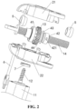
FIG. 2 is an exploded view of the linear driver for electric furniture according to embodiment one of the present application. -
FIG. 3 is a sectional view of the linear driver for electric furniture according to embodiment one of the present application. -
FIG. 4 is a sectional view of a worm wheel according to embodiment one of the present application. -
FIG. 5 is an enlarged view of part A ofFIG. 3 . -
FIG. 6 is an enlarged view of part B ofFIG. 3 . -
FIG. 7 is a view of a second housing according to embodiment one of the present application. -
FIG. 8 is a structure view of a brake member according to embodiment one of the present application. -
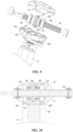
FIG. 9 is an exploded view of a linear driver for electric furniture according to embodiment two of the present application. -
FIG. 10 is a sectional view of the linear driver for electric furniture according to embodiment two of the present application. -
FIG. 11 is an enlarged view of part C ofFIG. 10 . -
FIG. 12 is an exploded view of a linear driver for electric furniture according to embodiment three of the present application. -
- 11
- motor
- 12
- worm
- 13
- worm wheel
- 131
- edge portion
- 132
- annular groove
- 14
- lead screw
- 21
- first housing
- 22
- second housing
- 23
- U-shaped portion
- 24
- second positioning member
- 25
- motor front end cap
- 250
- through hole
- 251
- limit step
- 252
- boss
- 3
- guide structure
- 31
- third positioning member
- 32
- guide hole
- 321
- arc slot
- 41
- bearing
- 42
- shaft sleeve
- 421
- first positioning member
- 43
- gasket
- 44
- elastic element
- 5
- first limit member
- 6
- wire
- 7
- brake member
- 71
- notch
- 72
- cut
- 73
- friction surface
- The solutions of the present application are further described hereinafter through embodiments in conjunction with drawings. It is to be understood that the embodiments set forth below are merely intended to illustrate the present application. It is to be further noted that for convenience of description, only some but not all structures related to the embodiments of the present application are shown in accompanying drawings. It should also be noted that, for ease of description, only part and not all of the present application are shown in drawings.
- As shown in
FIGS. 1 to 3 , this embodiment provides a linear driver for electric furniture. The linear driver includes a housing, aworm 12 with one end extending into the housing, aworm wheel 13 disposed in the housing and meshing with theworm 12, and alead screw 14. Thelead screw 14 penetrates through theworm wheel 13 and is in threaded connection with theworm wheel 13. At least one end of thelead screw 14 extends out of the housing to connect a movable portion of the electric furniture. In an embodiment, theworm wheel 13 is configured to restrict the movement of thelead screw 14 relative to theworm wheel 13 along the axial direction of thelead screw 14. - The
worm 12 rotates to drive the rotation of theworm wheel 13 which meshes with theworm 12. In this manner, thelead screw 14 drives the mounting bracket of the electric furniture to operate. - In an embodiment, the
lead screw 14 is connected to the fixing portion of the electric furniture, and thelead screw 14 can be fixed relative to the ground so that when theworm 11 rotates, the housing, theworm wheel 13, and themotor 11 which is connected to theworm 12 can move relative to the ground. - In an embodiment, the housing is connected to the fixing portion of the electric furniture, and the housing can be fixed relative to the ground so that when the
worm 11 rotates, thescrew lead 14 can move relative to the ground. - In an embodiment, the
worm wheel 13 is configured to rotate relative to the housing, but theworm wheel 13 cannot move relative to the housing along the axial direction of theworm wheel 13 or can move only slightly relative to the housing along the axial direction of theworm wheel 13. That is, theworm wheel 13 is restricted from moving relative to the housing along the axial direction of theworm wheel 13. - The electric furniture may be an electric sofa, an electric table, or an electric bed. The linear driver is usually directly secured to the fixing portion of the electric furniture. In an embodiment, a
U-shaped portion 23 is formed on the housing and configured to be connected to, for example, the fixing portion of an electric sofa frame or an electric bed frame. - To connect the
lead screw 14 to the movable portion of the electric furniture, in this embodiment, one end of thelead screw 14 extends out of the housing and is connected to a connecting portion fixed relative thelead screw 14. The connecting portion is configured to connect the movable portion of the electric furniture. The connecting portion and thelead screw 14 may be integrally formed, or the connecting portion may be separate from and secured to thelead screw 14. - In other embodiments, two ends of the
lead screw 14 may extend out of the housing and are each connected to a connecting portion fixed relative to thelead screw 14. - In another embodiment, a connecting hole may be formed at least one end of the
lead screw 14 extending out of the housing. Thelead screw 14 is connected to the movable portion of the electric furniture through the connecting hole. Optionally, an oil-containing shaft sleeve or a plastic-made bearing may be disposed in the connecting hole depending on the actual requirements. - The preceding linear driver for electric furniture also includes a power source. The power source in this embodiment is the
motor 11. The output shaft of themotor 11 and theworm 12 are integrally formed, or are connected as a whole. Themotor 11 is connected to awire 6 for connecting a power supply and a control switch. The power supply is electrically connected to themotor 11 through thewire 6 for supplying power to themotor 11. The control switch is electrically connected to themotor 11 through thewire 6 and controls themotor 11 to rotate forward or reversely through the control switch. In other embodiments, the power source may also be an electric machine. - In an embodiment, to define the travel of the
lead screw 14, the preceding linear driver for electric furniture also includes a limit assembly for limiting the extreme position to which thelead screw 14 is movable. In an embodiment, the limit assembly includes afirst limit member 5 and a second limit member. Two ends of thelead screw 14 extend out of the housing and are each connected to afirst limit member 5. Thefirst limit member 5 is sleeved around thelead screw 14, and an elastic pin shaft penetrates through thefirst limit member 5 and thelead screw 14 to fix thefirst limit member 5 relative to thelead screw 14. The housing is provided with a second limit member. The second limit member is a limit switch electrically connected to themotor 11. Optionally, the limit switch is a microswitch. During the movement of thelead screw 14 relative to the housing, once the second limit switch contacts the first limit member, the motor will stop rotating, maintaining thelead screw 14 in the current state. In other embodiments, the first limit member may be a limit switch. - To improve the stability of the
lead screw 14 when moving relative to theworm wheel 13, at least one end of theworm wheel 13 is provided with aguide structure 3. Theguide structure 3 is sleeved around thelead screw 14 and is in clearance fit with thelead screw 14. Theguide structure 3 is fixed relative to theworm wheel 13. Optionally, two ends of theworm wheel 13 are each provided with aguide structure 3 to improve the stability of thelead screw 14 when moving relative to theworm wheel 13. The size of the clearance between theguide structure 3 and thelead screw 14 in clearance fit can be determined by multiple repeated tests. - In this embodiment, the
guide structure 3 and theworm wheel 13 are integrally formed. In an embodiment, as shown inFIGS. 3 to 5 , two ends of theworm wheel 13 in the axial direction are each provided with anedge portion 131 integrally formed with theworm wheel 13. Theedge portion 131 is provided with aguide hole 32. Theguide hole 32 is a smooth hole. Thelead screw 14 penetrates through theguide hole 32. The inner wall of theguide hole 32 and thelead screw 14 are in clearance fit to form theguide structure 3. The movement of thelead screw 14 relative to theworm wheel 13 is guided by theguide structure 3 so that the coaxiality of thelead screw 14 and theworm wheel 13 is improved, avoiding the tilt of thelead screw 14 relative to theworm wheel 13 which causes locked-rotor of themotor 11. - Optionally, in this embodiment, the inner wall of the
guide hole 32 is provided with a first oil-storage slot for storing lubricating oil to lubricate thelead screw 14 so as to ensure smooth rotation of thelead screw 14. - In an embodiment, to facilitate the installation and replacement of the
worm wheel 13, the housing includes afirst housing 21 and asecond housing 22. Thefirst housing 21 and thesecond housing 22 are detachably connected. In this embodiment, thefirst housing 21 and thesecond housing 22 are connected to each other by multiple screws arranged in a circumferential direction. In other embodiments, thefirst housing 21 and thesecond housing 22 may also be connected to each other by snap fit or threaded connection. - In an embodiment, to limit the
worm wheel 13 in the axial direction and support theworm wheel 13, at least oneedge portion 131 is provided with a supporting member, and theedge portion 131 can be rotated relative to the housing through the supporting member. In this embodiment, eachedge portion 131 is provided with a supporting member. One of the supporting members is abearing 41, and another of the supporting members is ashaft sleeve 42, improving the stability of theworm wheel 13. In other embodiments, a supporting member may be disposed on only oneedge portion 131, and the supporting member may be a bearing 41 or ashaft sleeve 42. To limit theworm wheel 13 in the axial direction, the end face of theedge portion 131 with no supporting member sleeved around abuts against the inner wall of the housing. - In an embodiment, a
bearing 41 is sleeved around oneedge portion 131. The inner ring of thebearing 41 is fixed relative to theedge portion 131, and the outer ring of thebearing 41 is fixed relative to the housing. Ashaft sleeve 42 is sleeved around anotheredge portion 131. Theshaft sleeve 42 is fixed relative to the housing. Optionally, the bearing 41 uses a ball bearing. The inner ring of thebearing 41 may be fixed relative to theedge portion 131 in interference fit. - Since the outer ring of the
bearing 41 is fixed relative to the housing and the inner ring and the outer ring of thebearing 41 cannot move in the axial direction, the bearing 41 indirectly functions to limit theworm wheel 13 in the axial direction. Theworm wheel 13 is supported and limited in the axial direction by thebearing 41 and theshaft sleeve 42, increasing the stability of thelead screw 14. - In an embodiment, as shown in
FIGS. 2 ,3 , and6 , the outer peripheral wall of theshaft sleeve 42 is provided with afirst positioning member 421, the inner wall of the housing is provided with asecond positioning member 24, and thefirst positioning member 421 and thesecond positioning member 24 are inserted together to limit the movement of theshaft sleeve 42 in the axial direction and the circumferential direction. In this embodiment, thefirst positioning member 421 is a protrusion, and thesecond positioning member 24 is a groove. Optionally, multiplefirst positioning members 421 are provided. Thefirst positioning members 421 are uniformly distributed along the circumferential direction of the outer wall of theshaft sleeve 42. Thefirst positioning members 421 are in one-to-one correspondence withsecond positioning members 24. In other embodiments, thefirst positioning member 421 may be a groove, and thesecond positioning member 24 may be a protrusion. - In an embodiment, to avoid movement of the
worm wheel 13 in the axial direction during rotation, in this embodiment, theshaft sleeve 42 is fixed relative to the housing. Anelastic element 44 is sandwiched between theshaft sleeve 42 and theworm wheel 13. In an embodiment, anannular groove 132 is disposed on the side of theworm wheel 13 facing theshaft sleeve 42. Theelastic member 44 is mounted in theannular groove 132. Agasket 43 is disposed between theworm wheel 13 and theshaft sleeve 42. The outer diameter of thegasket 43 is larger than the maximum outer diameter of theannular groove 132 so that thegasket 43 can abut against the axial end face of theworm wheel 13. Thegasket 43 is pressed by theshaft sleeve 42 so that theelastic member 44 is pressed into theannular groove 132, and the vibration is damped by the deformation of theelastic member 44, thereby preventing theworm wheel 13 from moving in the axial direction. Optionally, thegasket 43 is a corrugated gasket, and theelastic member 44 is a rubber member. - In other embodiments, two
shaft sleeves 42 may be used to support theworm wheel 13 and to limit theworm wheel 13 in the axial direction. Oneshaft sleeve 42 is sleeved around eachedge portion 131, and theshaft sleeve 42 is fixed relative to the housing inner wall. In an embodiment, agasket 43 is disposed between eachshaft sleeve 42 and the axial end face of theworm wheel 13 to avoid that theworm wheel 13 jams on theshaft sleeve 42 when being assembled. One axial end face of theworm wheel 13 is provided with theannular groove 132. Theelastic member 44 is mounted in theannular groove 132. Theelastic member 44 abuts against thegasket 43. One side of theworm wheel 13 is limited by theshaft sleeve 42, and the other side of theworm wheel 13 is limited by theelastic member 44 in cooperation with theshaft sleeve 42, thereby preventing theworm wheel 13 from moving in the axial direction during rotation. - In other embodiments, two
bearings 41 may be used to support theworm wheel 13 and to limit theworm wheel 13 in the axial direction. In an embodiment, onebearing 41 may be sleeved around eachedge portion 131 at two ends of theworm wheel 13. The inner ring of abearing 41 is fixed relative to theedge portion 131, and the outer ring of thebearing 41 is fixed relative to the housing. Both the twobearings 41 can limit theworm wheel 13 in the axial direction, thereby preventing theworm wheel 13 from moving in the axial direction during rotation. - In an embodiment, the inner wall of the preceding
shaft sleeve 42 is provided with a second oil-storage slot for storing lubricating oil to lubricate theedge portion 131 to ensure smooth rotation of theworm wheel 13. - In an embodiment, as shown in
FIGS. 7 and 8 , the preceding linear driver for electric furniture also includes abrake member 7 connected to the housing and sleeved around theworm 12. Thebrake member 7 is elastically deformable to provide theworm 12 with a braking force opposite to the rotational direction of theworm 12. In an embodiment, the outer side of thesecond housing 22 is connected to a motorfront end cap 25. The motorfront end cap 25 is provided with a throughhole 250, and the inner wall of the throughhole 250 is provided withmultiple limit steps 251 arranged in the circumferential direction. Each of at least onelimit step 251 is provided with aboss 252. The outer peripheral wall of thebrake member 7 is provided withmultiple notches 71. Thenotch 71 and theboss 252 are in one-to-one correspondence and are inserted together so that thebrake member 7 is secured to the motorfront end cap 25 in a non-rotatable manner. - The end outer wall of the
worm 12 facing themotor 11 is a cylindrical surface with no worm teeth. The free end of theworm 12 extends through thebrake member 7 and extends into thesecond housing 22. Thebrake member 7 is provided withmultiple cuts 72, and thecuts 72 and thenotches 71 are alternately arranged along the circumferential direction of thebrake member 7. The provision of thecuts 72 and thenotches 71 provides space for elastic deformation of thebrake member 7. The surface on which thebrake member 7 contacts theworm 12 forms afriction surface 73. Thefriction surface 73 cooperates with the cylindrical surface with no worm teeth on theworm 12 during rotation of theworm 12 to provide a braking force for theworm 12. The structure of thebrake member 7 and how thebrake member 7 brakes theworm 12 may adopt techniques in the related art, and will not be described in detail. - To avoid damage to the surface of the
worm 12 caused by thebrake member 7 during rotation of theworm 12, the material hardness of thebrake member 7 is required to be less than the material hardness of theworm 12. - The present embodiment also provides electric furniture including the preceding linear driver for electric furniture, which can improve the coaxiality of the
lead screw 14 and theworm wheel 13, and effectively avoiding the tilt of thelead screw 14 relative to theworm wheel 13 which causes locked-rotor of themotor 11, thereby ensuring the normal use of the folding or lifting functions of the electric furniture. - As shown in
FIGS. 9 to 11 , this embodiment differs from embodiment one in that the structure of theguide structure 3 is different. In this embodiment, theguide structure 3 is disposed on the housing. In an embodiment, each of thefirst housing 21 and thesecond housing 22 is provided with anarc slot 321. Thearc slot 321 on thefirst housing 21 and thearc slot 321 on thesecond housing 22 are in one-to-one correspondence and are opened towards each other. Thearc slots 321 opened towards each other form aguide hole 32, and the inner wall of theguide hole 32 is in clearance fit with thelead screw 14 to form theguide structure 3. The inner wall of theguide hole 32 is in clearance fit with thelead screw 14 so that thelead screw 14 is guided and will not tilt, thereby ensuring the stability of the movement and rotation of thelead screw 14 relative to the housing. In this embodiment, twoguide holes 32 are provided. The twoguide holes 32 are respectively disposed at two ends of theworm wheel 13 in the axial direction. The two ends of thelead screw 14 penetrate out of the housing from the two guide holes 32. - Optionally, the inner wall of the
guide hole 32 is provided with a first oil-storage slot for storing lubricating oil to lubricate thelead screw 14, thereby ensuring smooth rotation of thelead screw 14 relative to theguide hole 32. - To limit the
worm wheel 13, two ends of theworm wheel 13 are each provided with anedge portion 131, and eachedge portion 131 is provided with a supporting member. The supporting member is ashaft sleeve 42 fixed relative to the housing. In an embodiment, the outer wall of theshaft sleeve 42 is provided with afirst positioning member 421. The inner wall of the housing is provided with asecond positioning member 24. Thefirst positioning member 421 and thesecond positioning member 24 are inserted together to limit the movement of theshaft sleeve 42 in the axial direction and the circumferential direction. In this embodiment, thefirst positioning member 421 is a protrusion, and thesecond positioning member 24 is a groove. Optionally, multiplefirst positioning members 421 are provided. Thefirst positioning members 421 are uniformly distributed along the circumferential direction of the outer wall of theshaft sleeve 42, and thefirst positioning members 421 are in one-to-one correspondence to thesecond positioning members 24. In other embodiments, thefirst positioning member 421 may be a groove, and thesecond positioning member 24 may be a protrusion. - In an embodiment, to avoid that the
shaft sleeve 42 jams on theworm wheel 13 when being assembled, agasket 43 is disposed between eachshaft sleeve 42 and the axial end face of theworm wheel 13 facing the eachshaft sleeve 42. Optionally, thegasket 43 is a corrugated gasket. - In an embodiment, to avoid movement of the
worm wheel 13 in the axial direction during rotation, this embodiment provides anelastic element 44 between oneshaft sleeve 42 and the end face of theworm wheel 13 facing the oneshaft sleeve 42. In an embodiment, one axial end face of theworm wheel 13 is provided with anannular groove 132. Theelastic member 44 is mounted in theannular groove 132. Thegasket 43 abuts against theelastic member 44, and theshaft sleeve 42 abuts against thegasket 43 so that the vibration is damped by the deformation of theelastic member 44, thereby preventing theworm wheel 13 from moving in the axial direction. - Optionally, the inner wall of the
shaft sleeve 42 is provided with a second oil-storage slot for storing lubricating oil to lubricate the outer wall of theedge portion 131 to ensure smooth rotation of theworm wheel 13. - In other embodiments, one
bearing 41 may be sleeved around eachedge portion 131. The inner ring of abearing 41 is fixed relative to theworm wheel 13, and the outer ring of thebearing 41 is fixed relative to the housing to replace theshaft sleeve 42. - In other embodiments, a
bearing 41 may be sleeved around oneedge portion 131, where the inner ring of thebearing 41 is fixed relative to theworm wheel 13, and the outer ring of thebearing 41 is fixed relative to the housing. Ashaft sleeve 42 fixed relative to the housing is sleeved around anotheredge portion 131, where agasket 43 is disposed between ashaft sleeve 42 and the axial end face of theworm wheel 13 facing theshaft sleeve 42 to avoid that theshaft sleeve 42 jams on theworm wheel 13 when being assembled. One axial end face of theworm wheel 13 is provided with anannular groove 132. Theelastic member 44 is mounted in theannular groove 132. Thegasket 43 abuts against theelastic member 44, and theshaft sleeve 42 abuts against thegasket 43 so that the vibration is damped by the deformation of theelastic member 44, thereby preventing theworm wheel 13 from moving in the axial direction. - As shown in
FIG. 12 , this embodiment differs from other embodiments in that the structure of theguide structure 3 is different. In this embodiment, theguide structure 3 is separate from the housing and theworm wheel 13 and is fixed relative to the housing. In an embodiment, theguide structure 3 is a sleeve. The sleeve is sleeved around thelead screw 14, and the inner wall of the sleeve is in clearance fit with thelead screw 14. The outer wall of the sleeve is provided with athird positioning member 31, and the inner wall of the housing is provided with a fourth positioning member. Thethird positioning member 31 and the fourth positioning member are inserted together to limit the movement of the sleeve in the axial direction and the circumferential direction. In this embodiment, thethird positioning member 31 is a protrusion, and the fourth positioning member is groove. - Optionally, multiple
third positioning members 31 are provided. Thethird positioning members 31 are uniformly distributed along the circumferential direction of the sleeve, and a fourth positioning member is in one-to-one correspondence with athird positioning member 31. In other embodiments, thethird positioning member 31 may be a groove, and the fourth positioning member may be a protrusion. - Optionally, the inner wall of the sleeve is provided with a first oil-storage slot to lubricate the
lead screw 14 to ensure smooth rotation of thelead screw 14. - In an embodiment, two ends in the axial direction of the
worm wheel 13 are each provided with anedge portion 131 connected thereto, and eachedge portion 131 is provided with a supporting member. The supporting member is abearing 41. The inner ring of thebearing 41 is fixed relative to theedge portion 131, and the outer ring of thebearing 41 is fixed relative to the housing. Theworm wheel 13 is supported and limited in the axial direction by twobearings 41. The twobearings 41 are used to limit theworm wheel 13 in the axial direction to prevent theworm wheel 13 from moving in the axial direction during rotation. - In other embodiments, a
shaft sleeve 42 fixed relative to the housing may be sleeved around eachedge portion 131, or ashaft sleeve 42 fixed relative to the housing may be sleeved around oneedge portion 131, and abearing 41 is sleeved around anotheredge portion 131. The inner ring of thebearing 41 is fixed relative to theedge portion 131, and the outer ring of thebearing 41 is fixed relative to the housing. The two ways of supporting theworm wheel 13 and limiting theworm wheel 13 in the axial direction are the same as the previously described and are not repeated here. - In this embodiment, two
guide structures 3 are provided. The twoguide structures 3 are disposed at the two ends of theworm wheel 13. The present embodiment differs from the present other embodiments in that one of theguide structures 3 uses theguide hole 32 in clearance fit with thelead screw 14 and disposed on theedge portion 131 in embodiment one, and theother guide structure 3 uses theguide hole 32 in clearance fit with thelead screw 14 and disposed on the housing in embodiment two. - In other embodiments, one of the
guide structures 3 may use theguide hole 32 in clearance fit with thelead screw 14 and disposed on theedge portion 131 in embodiment one, and theother guide structure 3 may use the sleeve in clearance fit with thelead screw 14 in embodiment three. - In another embodiment, one of the
guide structures 3 may use theguide hole 32 in clearance fit with thelead screw 14 and disposed on the housing in embodiment two, and theother guide structure 3 may use the sleeve in clearance fit with thelead screw 14 in embodiment three. - In the linear driver for electric furniture provided by the present application, a guide structure is disposed on at least one end of the worm wheel. The guide structure is fixed relative to the housing or the worm wheel. The guide structure is sleeved around the lead screw and is in clearance fit with the lead screw. The movement of the lead screw to the worm wheel is guided by the guide structure so that the coaxiality of the lead screw and the worm wheel is improved, preventing the lead screw from tilting relative to the worm wheel and then influencing the normal movement of the lead screw.
- The electric furniture provided by the present application includes the preceding linear driver for electric furniture so that the coaxiality of the worm wheel and the lead screw can be effectively improved, thereby ensuring the normal use of the folding or lifting functions of the electric furniture.
- In the description of the present application, it is to be noted that the orientations or position relations indicated by terms such as "center", "above", "below", "left", "right", "vertical", "horizontal", "inside", "outside", and the like are based on orientations or position relations shown in the drawings. These orientations or position relations are intended only to facilitate and simplify the description of the present application and not to indicate or imply that an apparatus or element referred to must have such specific orientations or must be configured or operated in such specific orientations. In addition, terms such as "first" and "second" are used only for the purpose of description and are not to be construed as indicating or implying relative importance. Terms "first position" and "second position" are two different positions.
- In the description of the present application, it is to be noted that unless otherwise expressly specified and limited, the term "mounted", "connected to each other" or "connected" should be construed in a broad sense as securely connected, detachably connected or integrally connected; mechanically connected or electrically connected; directly connected to each other or indirectly connected to each other via an intermediary; or intraconnected between two components. For those of ordinary skill in the art, meanings of the preceding terms can be understood according to situations in the present application.
Claims (17)
- A linear driver for electric furniture, comprising a housing, a worm (12) with one end extending into the housing, a worm wheel (13) disposed in the housing and meshing with the worm (12), and a lead screw (14), wherein the lead screw (14) penetrates through the worm wheel (13) and is in threaded connection with the worm wheel (13), at least one end of the lead screw (14) extends out of the housing, at least one end of the worm wheel (13) is provided with a guide structure (3), the guide structure (3) is sleeved around the lead screw (14) and in clearance fit with the lead screw (14), and the guide structure (3) is fixed relative to the worm wheel (13) or the housing.
- The linear driver for electric furniture according to claim 1, wherein the guide structure (3) and the worm wheel (13) are integrally formed.
- The linear driver for electric furniture according to claim 2, wherein the worm wheel (13) is provided with an edge portion (131) at one end of the worm wheel (13) along an axial direction of the worm wheel (13) or is provided with an edge portion (131) at each of two ends of the worm wheel (13) along an axial direction of the worm wheel (13), wherein the edge portion (131) is integrally formed with the worm wheel (13), the edge portion (131) is provided with a guide hole (32), the lead screw (14) penetrates through the guide hole (32) and is in clearance fit with an inner wall of the guide hole (32), and the guide structure (3) comprises the guide hole (32).
- The linear driver for electric furniture according to claim 1, wherein the guide structure (3) is disposed on the housing.
- The linear driver for electric furniture according to claim 4, wherein the housing comprises a first housing (21) and a second housing (22) connected to each other, the first housing (21) and the second housing (22) are each provided with an arc slot (321), the arc slot (321) on the first housing (21) and the arc slot (321) on the second housing (22) are in one-to-one correspondence with each other and are opened towards each other, the arc slots (321) opened towards each other form a guide hole (32), the lead screw (14) penetrates through the guide hole (32) and is in clearance fit with an inner wall of the guide hole (32), and the guide structure (3) comprises the guide hole (32).
- The linear driver for electric furniture according to claim 1, wherein the guide structure (3) is separate from the housing and is fixed relative to the housing.
- The linear driver for electric furniture according to claim 6, wherein the lead screw (14) is surrounded by a sleeve fixed relative to the housing, an inner wall of the sleeve is in clearance fit with the lead screw (14), and the guide structure (3) comprises the sleeve.
- The linear driver for electric furniture according to any one of claims 1 to 7, wherein an inner wall of a hole of the guide structure (3) in clearance fit with the lead screw (14) is provided with a first oil-storage slot.
- The linear driver for electric furniture according to any one of claims 1 to 7, wherein the worm wheel (13) is provided with an edge portion (131) at one end of the worm wheel (13) along an axial direction of the worm wheel (13) or is provided with an edge portion (131) at each of two ends of the worm wheel (13) along an axial direction of the worm wheel (13), wherein the edge portion (131) is connected to the worm wheel (13), the edge portion (131) is sleeved with a support, the edge portion (131) is configured to rotate relative to the housing through the support, and the support comprises at least one of a bearing (41) or a shaft sleeve (42).
- The linear driver for electric furniture according to claim 9, wherein an inner wall of the shaft sleeve (42) is provided with a second oil-storage slot.
- The linear driver for electric furniture according to claim 9, wherein the shaft sleeve (42) is fixed relative to the housing, and an elastic element (44) is sandwiched between the shaft sleeve (42) and the worm wheel (13).
- The linear driver for electric furniture according to any one of claims 1 to 7, further comprising a brake member (7) connected to the housing and sleeved around the worm (12), the brake member (7) is elastically deformable, the brake member (7) is configured to provide the worm (12) with a braking force opposite to a rotational direction of the worm (12).
- The linear driver for electric furniture according to any one of claims 1 to 7, wherein the housing is provided with a U-shaped portion configured to be connected to a fixing portion of the electric furniture.
- The linear driver for electric furniture according to any one of claims 1 to 7, further comprising a limit assembly configured to limit an extreme position to which the lead screw (14) is movable.
- The linear driver for electric furniture according to claim 14, wherein the limit assembly comprises:a first limit member (5) disposed at each of two ends of the lead screw (14) and fixed relative to the lead screw (14); anda second limit member disposed on the housing and in one-to-one correspondence with the first limit member (5),wherein of the first limit member (5) and the second limit member corresponding to the first limit member (5), one is a limit switch electrically connected to a power source connected to the worm (12), and the other is configured to cause the limit switch to control the power source to stop operating.
- The linear driver for electric furniture according to any one of claims 1 to 7, wherein a connecting hole for connecting a movable portion of the electric furniture is formed at an end of the lead screw (14), wherein the end penetrates out of the housing; or
a connecting portion fixed relative to the lead screw (14) and configured to connect a movable portion of the electric furniture is connected to an end of the lead screw (14), wherein the end penetrates out of the housing. - Electric furniture, comprising the linear driver for electric furniture according to any one of claims 1 to 16.
Applications Claiming Priority (3)
| Application Number | Priority Date | Filing Date | Title |
|---|---|---|---|
| CN202011519244.2A CN112583198A (en) | 2020-12-21 | 2020-12-21 | Linear driver for electric furniture and electric furniture |
| CN202023098469.3U CN213754228U (en) | 2020-12-21 | 2020-12-21 | Linear driver for electric furniture and electric furniture |
| PCT/CN2021/070573 WO2022134222A1 (en) | 2020-12-21 | 2021-01-07 | Linear driver for electric furniture, and electric furniture |
Publications (2)
| Publication Number | Publication Date |
|---|---|
| EP4213352A1 true EP4213352A1 (en) | 2023-07-19 |
| EP4213352A4 EP4213352A4 (en) | 2024-02-28 |
Family
ID=82158775
Family Applications (1)
| Application Number | Title | Priority Date | Filing Date |
|---|---|---|---|
| EP21908241.9A Pending EP4213352A4 (en) | 2020-12-21 | 2021-01-07 | Linear driver for electric furniture, and electric furniture |
Country Status (3)
| Country | Link |
|---|---|
| US (1) | US20240011542A1 (en) |
| EP (1) | EP4213352A4 (en) |
| WO (1) | WO2022134222A1 (en) |
Family Cites Families (9)
| Publication number | Priority date | Publication date | Assignee | Title |
|---|---|---|---|---|
| DE102005001333A1 (en) * | 2005-01-11 | 2006-07-27 | Ims Gear Gmbh | Transmission for an adjustment |
| EP2001703B1 (en) * | 2006-03-27 | 2017-12-13 | Johnson Controls Technology Company | Transmission device for seat adjuster |
| JP5216344B2 (en) * | 2008-01-31 | 2013-06-19 | 株式会社ミツバ | Seat drive device |
| DE202009001847U1 (en) * | 2009-02-11 | 2010-07-01 | Brose Fahrzeugteile Gmbh & Co. Kommanditgesellschaft, Coburg | Spindle drive for a seat-length adjustment of a motor vehicle seat |
| CN106799976B (en) * | 2017-03-22 | 2023-10-27 | 苏州星诺奇科技股份有限公司 | Transmission device for automobile seat regulator |
| CN207364215U (en) * | 2017-09-07 | 2018-05-15 | 上海艺崇机械制造厂 | A kind of lifting structure |
| DE202019103343U1 (en) * | 2019-06-14 | 2020-09-15 | Dewertokin Gmbh | Electric motor drive with braking device |
| CN210318408U (en) * | 2019-06-18 | 2020-04-14 | 宁波东力传动设备有限公司 | Worm gear transmission structure without bearing support |
| CN210404975U (en) * | 2019-09-11 | 2020-04-24 | 宁波市奉化润达医疗器械有限公司 | Stable form electric putter |
-
2021
- 2021-01-07 US US18/034,909 patent/US20240011542A1/en active Pending
- 2021-01-07 EP EP21908241.9A patent/EP4213352A4/en active Pending
- 2021-01-07 WO PCT/CN2021/070573 patent/WO2022134222A1/en active Application Filing
Also Published As
| Publication number | Publication date |
|---|---|
| US20240011542A1 (en) | 2024-01-11 |
| EP4213352A4 (en) | 2024-02-28 |
| WO2022134222A1 (en) | 2022-06-30 |
Similar Documents
| Publication | Publication Date | Title |
|---|---|---|
| US8051737B2 (en) | Worm gear drive | |
| EP2232101B1 (en) | Linear actuator | |
| JP4632955B2 (en) | Rotating electric machine and electric vehicle | |
| EP3575634A1 (en) | Drive assembly and lifting column | |
| JP4275039B2 (en) | Motor with reduction mechanism and power seat motor with reduction mechanism | |
| EP2944847A2 (en) | Actuator and application of same | |
| US20070212211A1 (en) | Cross flow fan apparatus, electronic apparatus and impeller | |
| CN100570176C (en) | Linear actuators | |
| JP4918234B2 (en) | Linear actuator and linear actuator device | |
| EP2497973A1 (en) | Apparatus comprising a multi-motion assembly with a leadscrew system and method for operating such an apparatus | |
| US11539266B2 (en) | Electromotive furniture drive comprising a drive motor with a brake device | |
| US10920862B2 (en) | Actuator having manual rotating and anti-pinch mechanisms | |
| EP4213352A1 (en) | Linear driver for electric furniture, and electric furniture | |
| EP0681359A1 (en) | An electromechanical actuator having a supporting and containing housing | |
| CN213754228U (en) | Linear driver for electric furniture and electric furniture | |
| CN112583198A (en) | Linear driver for electric furniture and electric furniture | |
| CN114043455A (en) | Small-size industrial desktop mechanical arm and base, robot thereof | |
| EP4210205A1 (en) | One-way self-locking driver | |
| EP4257846A1 (en) | Driver having self-locking function, and linear actuator | |
| JP6118132B2 (en) | Linear actuator | |
| CN110170837B (en) | Various steel composite sheet goes up and down cutting device | |
| KR200489020Y1 (en) | Actuator apparatus having damping means | |
| JP2018148656A (en) | Direct-acting mechanism | |
| US3586399A (en) | Oil-free bearing assembly with device for suppression of bearing noise | |
| CN211986553U (en) | Injection pump |
Legal Events
| Date | Code | Title | Description |
|---|---|---|---|
| STAA | Information on the status of an ep patent application or granted ep patent |
Free format text: STATUS: THE INTERNATIONAL PUBLICATION HAS BEEN MADE |
|
| PUAI | Public reference made under article 153(3) epc to a published international application that has entered the european phase |
Free format text: ORIGINAL CODE: 0009012 |
|
| STAA | Information on the status of an ep patent application or granted ep patent |
Free format text: STATUS: REQUEST FOR EXAMINATION WAS MADE |
|
| 17P | Request for examination filed |
Effective date: 20230414 |
|
| AK | Designated contracting states |
Kind code of ref document: A1 Designated state(s): AL AT BE BG CH CY CZ DE DK EE ES FI FR GB GR HR HU IE IS IT LI LT LU LV MC MK MT NL NO PL PT RO RS SE SI SK SM TR |
|
| A4 | Supplementary search report drawn up and despatched |
Effective date: 20240126 |
|
| RIC1 | Information provided on ipc code assigned before grant |
Ipc: A61G 7/018 20060101ALI20240122BHEP Ipc: F16H 37/12 20060101ALI20240122BHEP Ipc: H02K 7/116 20060101ALI20240122BHEP Ipc: H02K 7/06 20060101AFI20240122BHEP |
|
| DAV | Request for validation of the european patent (deleted) | ||
| DAX | Request for extension of the european patent (deleted) |