EP4212811A1 - A flat tube - Google Patents
A flat tube Download PDFInfo
- Publication number
- EP4212811A1 EP4212811A1 EP22151651.1A EP22151651A EP4212811A1 EP 4212811 A1 EP4212811 A1 EP 4212811A1 EP 22151651 A EP22151651 A EP 22151651A EP 4212811 A1 EP4212811 A1 EP 4212811A1
- Authority
- EP
- European Patent Office
- Prior art keywords
- wall
- tube
- main
- deformation
- flat tube
- Prior art date
- Legal status (The legal status is an assumption and is not a legal conclusion. Google has not performed a legal analysis and makes no representation as to the accuracy of the status listed.)
- Granted
Links
Images

Classifications
-
- F—MECHANICAL ENGINEERING; LIGHTING; HEATING; WEAPONS; BLASTING
- F28—HEAT EXCHANGE IN GENERAL
- F28D—HEAT-EXCHANGE APPARATUS, NOT PROVIDED FOR IN ANOTHER SUBCLASS, IN WHICH THE HEAT-EXCHANGE MEDIA DO NOT COME INTO DIRECT CONTACT
- F28D1/00—Heat-exchange apparatus having stationary conduit assemblies for one heat-exchange medium only, the media being in contact with different sides of the conduit wall, in which the other heat-exchange medium is a large body of fluid, e.g. domestic or motor car radiators
- F28D1/02—Heat-exchange apparatus having stationary conduit assemblies for one heat-exchange medium only, the media being in contact with different sides of the conduit wall, in which the other heat-exchange medium is a large body of fluid, e.g. domestic or motor car radiators with heat-exchange conduits immersed in the body of fluid
- F28D1/03—Heat-exchange apparatus having stationary conduit assemblies for one heat-exchange medium only, the media being in contact with different sides of the conduit wall, in which the other heat-exchange medium is a large body of fluid, e.g. domestic or motor car radiators with heat-exchange conduits immersed in the body of fluid with plate-like or laminated conduits
- F28D1/0391—Heat-exchange apparatus having stationary conduit assemblies for one heat-exchange medium only, the media being in contact with different sides of the conduit wall, in which the other heat-exchange medium is a large body of fluid, e.g. domestic or motor car radiators with heat-exchange conduits immersed in the body of fluid with plate-like or laminated conduits a single plate being bent to form one or more conduits
-
- F—MECHANICAL ENGINEERING; LIGHTING; HEATING; WEAPONS; BLASTING
- F28—HEAT EXCHANGE IN GENERAL
- F28F—DETAILS OF HEAT-EXCHANGE AND HEAT-TRANSFER APPARATUS, OF GENERAL APPLICATION
- F28F1/00—Tubular elements; Assemblies of tubular elements
- F28F1/02—Tubular elements of cross-section which is non-circular
- F28F1/022—Tubular elements of cross-section which is non-circular with multiple channels
-
- F—MECHANICAL ENGINEERING; LIGHTING; HEATING; WEAPONS; BLASTING
- F28—HEAT EXCHANGE IN GENERAL
- F28F—DETAILS OF HEAT-EXCHANGE AND HEAT-TRANSFER APPARATUS, OF GENERAL APPLICATION
- F28F1/00—Tubular elements; Assemblies of tubular elements
- F28F1/10—Tubular elements and assemblies thereof with means for increasing heat-transfer area, e.g. with fins, with projections, with recesses
- F28F1/42—Tubular elements and assemblies thereof with means for increasing heat-transfer area, e.g. with fins, with projections, with recesses the means being both outside and inside the tubular element
- F28F1/424—Means comprising outside portions integral with inside portions
- F28F1/426—Means comprising outside portions integral with inside portions the outside portions and the inside portions forming parts of complementary shape, e.g. concave and convex
-
- F—MECHANICAL ENGINEERING; LIGHTING; HEATING; WEAPONS; BLASTING
- F28—HEAT EXCHANGE IN GENERAL
- F28F—DETAILS OF HEAT-EXCHANGE AND HEAT-TRANSFER APPARATUS, OF GENERAL APPLICATION
- F28F1/00—Tubular elements; Assemblies of tubular elements
- F28F1/02—Tubular elements of cross-section which is non-circular
- F28F2001/027—Tubular elements of cross-section which is non-circular with dimples
Definitions
- the invention relates to a flat tube.
- the invention relates to a flat tube for a heat exchanger.
- Heat exchangers having folded flat tubes are well known in the art. Such heat exchangers typically include a plurality of the folded flat tubes spaced apart and arranged in parallel and extending between an inlet header tank and an outlet header tank.
- the inlet header tank receives a first fluid and distributes the first fluid between a plurality of flow pathways formed within the flat tubes.
- the first fluid exchanges heat energy with a second fluid flowing through the spaces between adjacent ones of the flat tubes. After exchanging the heat energy within the flat tubes, the first fluid is recombined within the outlet header tank before exiting the heat exchanger.
- One common construction of a flat tube includes folding a sheet of aluminum into a tubular structure wherein two opposing edges of the sheet are brought together and then brazed or welded at the resulting seam to form a substantially B-shaped flat tube.
- the central seam of the B-shaped flat tube is typically further reinforced by adding at least one fold to the opposing edges of the sheet.
- the folded over portions of the sheet of aluminum are positioned to abut an inner surface of the flat tube along a length thereof to form a longitudinally extending partition, wherein the partition divides a hollow interior of each of the flat tubes into two flow separate paths while also structurally reinforcing the flat tube along the central seam of the tube.
- the B-shaped folded flat tube construction has been found to be particularly susceptible to thermal cycling failure at an intersection of each of the tubes and each of the header tanks.
- Each of the tubes is inserted into an opening formed in each of the header tanks, the opening having a cross-sectional shape substantially similar to that of an outer surface of each of the tubes, thereby restricting outward deformation of the outer surface of each of the tubes.
- the central partition adds rigidity to the interior of each of the tubes further restricting relative movement between the opposing surfaces of each of the tubes adjacent the central partition.
- each of the tube ends and each of the header tanks exacerbates the incidence of failure due to thermal cycling because the different portions of the tubes experiencing different degrees of thermal expansion are restricted from moving and deforming relative to each other during use of the heat exchanger.
- the restricted motion may in some circumstances lead to elevated stresses within portions of each of the tubes that can lead to permanent deformation or eventual failure adjacent each of the header tanks.
- the object of the invention is, among others, a flat tube for the flow therein of a fluid in a heat exchanger, the tube being formed by bending a sheet metal strip along the length of the strip, the tube comprising: a first main wall; a second main wall parallel to the first main wall, said main walls being substantially flat; and two complementary side wall portions joining said main walls together so as to define a closed profile of the tube, said strip defining over its width a middle region and two intermediate regions on either side of said middle region, the first main wall of the tube being formed from said middle region, said second main wall of the tube comprising two wall portions each formed from a respective one of said intermediate regions, with said wall portions of the second main wall being juxtaposed in substantially a common plane, a median wall defined by a double thickness of the sheet metal strip with one part attached to a first wall portion and the other part attached to a second wall portion, and inner walls each formed from a respective one of said parts of the median wall, wherein a first piece of said inner wall is at least partially fixed and
- At least one deformation is disposed on at least one main wall .
- At least one deformation is disposed on at least one of side wall portions.
- At least one deformation is disposed on at least one of the wall portions.
- the deformation is in form of protrusion projecting inwardly towards the center of the intermediate region.
- the deformation is in form of protrusion projecting outwardly from the center of the intermediate region.
- the strip comprises at least one set of deformations, wherein the set is limited by the walls.
- the deformations are equidistant within the set, with respect to axis of elongation of the tube.
- the distance between consecutive deformations forming the set are different.
- the deformation has an oblong shape.
- the deformation has a pyramidal shape.
- the deformation has a substantially rectangular shape.
- the sheet metal strip comprises an outside surface and a layer of braze metal on said outside surface, said layer having been pre-applied on the corresponding surface of said strip.
- Another object of the invention is a heat exchanger comprising at least one flat tube .
- the deformations allow to increase the rigidity of the tube in desired regions, without using additional elements and without increasing the thickness of the metal sheet strip. Consequently, the tube is able to withstand thermal shock caused by the rapid temperature and/or pressure change of the fluid. Furthermore, the deformations may increase the overall performance of the heat exchanger by deflecting the path of the fluid flowing through the tube, so that the heat exchange may be increased.
- the subject-matter of the invention is a flat tube 1 for the flow therein of a fluid in a heat exchanger.
- the heat exchanger may be of any type as long as it is provided with so-called folded tubes.
- Such tube 1 may be formed by bending a sheet metal strip 2 along the length of the strip 2.
- the sheet of metal may be for example, aluminum.
- the tube 1 may comprise an outside surface and a layer of braze metal 3 thereon.
- the braze material 3 may be, for example, a flux.
- the flux is a chemical compound applied to the joint surfaces before brazing. Its use, with a few exceptions, is crucial in the atmospheric brazing process.
- the braze material 3 may thus be pre-applied on the corresponding surface of said strip 2 to enhance the quality of the brazing joint.
- the tube 1 may further comprise a first main wall 4, a second main wall 5 which is substantially parallel with respect to the first main wall 4.
- the main walls 4, 5 may be substantially flat.
- the terms "substantially parallel” and “substantially flat” should be understood as allowing some deviances from ideal. It is desired that the walls are perfectly parallel or perfectly flat, yet one must take into account that during the production process or during the operational mode of the heat exchanger some deviations may occur.
- the tube 1 may further comprise two complementary side wall portions 6 joining said main walls 4, 5 together so as to define a closed profile of the tube 1.
- Side wall portions 6 may be substantially arcuate in shape having a desired radius of curvature, but other shapes may be used without departing from the scope of the present invention.
- Fig. 2 shows a detailed view of a main wall of the tube of Fig.1 . It is notable that the braze material 3 is located on one side of the metal strip 2. This allows brazing all portions together.
- said strip 2 may define over its width a middle region and two intermediate regions on either side of said middle region.
- the middle region may comprise two channels for the fluid being separated by a median wall 7.
- the median wall 7 may divide the tube 1 into two substantially mirror-imaged portions.
- an embodiment in which the median wall is shifted towards either of the wall portions 6, or inclined so that it does not divide the tube 1 into two mirror-image portions is also envisaged.
- the median wall 7 may be twice the thickness of any of the main walls 4, 5 or any of the side wall portions 6.
- the first main wall 4 of the tube 1 may be formed from said middle region.
- the second main wall 5 of the tube 1 may comprise two wall portions 5A, 5B each formed from a respective one of said intermediate regions.
- the median wall 7 extends in the longitudinal direction of the tube 1, i.e. in the axis of elongation of the tube 1, and contacts the first and second main walls 4, 5.
- the portions forming the median wall 7 are preferably substantially perpendicular to the main walls 4,5.
- the median wall 7 is defined by a double thickness of the metal sheet strip 2 with one part attached to the second main wall 5 and is located intermediate the side wall portions 6 and the wall portions 5A, 5B. Further, the wall portions 5A. 5B of the second main wall 5 may be juxtaposed in substantially a common plane.
- the double thickness of the metal sheet strip 2 may extend in parallel to the first main wall 4 and within the respective middle region to form a first inner wall 8A and a second inner wall 8B.
- the wall portions inner walls 8A, 8B may protrude directly from the median wall 7 formed by the double thickness of the metal sheet strip 2 towards respective side wall portions 6.
- At least part of each inner wall 8A, 8B, namely a first piece, may be substantially parallel to the first main wall 4 and fixed thereto, for example, by brazing.
- the braze material 3 on corresponding side of the sheet metal strip 2 enhances the process of fixation.
- a respective second pieces of the inner walls 8A, 8B may protrude directly form the first pieces, yet they are no longer fixed to the first main wall 4.
- the second pieces may project towards the second main wall 5 and they may be fixed thereto. Further, the second pieces, similarly to side wall portions, be substantially arcuate in shape having a desired radius of curvature, but other shapes may be used without departing from the scope of the present invention. Substantially, the second pierces of the inner walls 8A, 8B may be fixed to the first main wall 4 so that the terminal end of second pieces face each other and at least portion of each of second pieces is substantially parallel to the second main wall 5. Said inner walls 8A, 8B along with the respective part of the median wall 7 and respective portions of the main walls 4, 5 may be regarded as the perimeter of the middle region of the tube 1.
- the strip 2 may further comprise at least one deformation 9.
- the desired locations of the deformations 9 are marked with an oval shapes.
- the deformations allow to locally deviate the surface of any of the walls 4,5,6, 5A, 5B 8A, 8B.
- the deformations 9 allow to increase the rigidity of the tube 1 in desired regions, without using additional elements and without increasing the thickness of the metal sheet strip. Consequently, the tube 1 is able to withstand thermal shock caused by the rapid temperature and/or pressure change of the fluid.
- the deformations 9 may increase the overall performance of the heat exchanger by deflecting the path of the fluid flowing through the tube 1, so that the heat exchange may be increased.
- the location and the number of the deformations 9 is not a liming factor, thus they may be allocated according to the desired effects.
- At least one deformation 9 may be disposed on at least one of the main walls 4,5.
- the deformations 9 may also be located on both main walls 4,5.
- At least one deformation 9 may disposed on at least one of side wall portions 6.
- the deformations 9 may also be located on both side wall portions 6.
- At least one deformation 9 may be disposed on at least one of the inner walls 8A, 8B.
- the deformations 9 may also be located on both inner walls 8A, 8B.
- at least one deformation 9 may be disposed on at least first piece of inner wall 8A, 8B or second piece of inner wall 8A, 8B.
- At least one deformation 9 may be disposed on at least one of the wall portions 5A, 5B.
- the deformations 9 may also be located on both wall portions 5A, 5B.
- one or more deformations located on the same wall 4, 5, 5A, 5B may form a set 99.
- Each set 99 may comprise a random pattern, i.e. one cannot distinguish any rule or conception according to which the deformations are allocated. However, it is more likely that one can distinguish pattern in which the set 99 of deformations 9 is allocated on particular wall 4, 5, 5A, 5B.
- the deformations 9 may be arranged in series.
- the distance between each deformation 9 of the set 99 may be equal or different or increasing.
- the deformations 9 may thus be equidistant within the set 99, with respect to axis of elongation of the tube 1.
- the deformations 9 may be arranged in zig-zag pattern.
- the distance between each deformation 9 of the set 99 may be equal or different or increasing.
- the deformation 9 may be in form of protrusion projecting inwardly towards the center of the middle region.
- the deformation 9 may deviate from the surface of the inner wall 8A, 8B towards the axis of the channel for the fluid formed in the middle portion.
- the deformations 9 project from a second piece of the inner wall 8A.
- the deformation 9 may be in form of protrusion projecting outwardly from the center of the middle region.
- the deformation 9 may deviate from the surface of the wall 4, 5, 8A, 8B away from the axis of the channel for the fluid formed in the middle portion.
- the deformations 9 may comprise different shapes and sizes. Thus, the shape or size of the deformation 9 does not limit the invention to any particular example.
- the deformation 9 may have an oblong shape, or a pyramidal shape, or a trapezoidal shape, or substantially rectangular shape.
- Another object of the invention may be a heat exchanger 100 comprising aforementioned flat tube 1.
- the flat tube 1 may provide a fluid communication between the manifolds, thus increasing overall performance thereof.
Landscapes
- Engineering & Computer Science (AREA)
- Physics & Mathematics (AREA)
- Thermal Sciences (AREA)
- Mechanical Engineering (AREA)
- General Engineering & Computer Science (AREA)
- Geometry (AREA)
- Heat-Exchange Devices With Radiators And Conduit Assemblies (AREA)
Abstract
Description
- The invention relates to a flat tube. In particular, the invention relates to a flat tube for a heat exchanger.
- Heat exchangers having folded flat tubes are well known in the art. Such heat exchangers typically include a plurality of the folded flat tubes spaced apart and arranged in parallel and extending between an inlet header tank and an outlet header tank. The inlet header tank receives a first fluid and distributes the first fluid between a plurality of flow pathways formed within the flat tubes. The first fluid exchanges heat energy with a second fluid flowing through the spaces between adjacent ones of the flat tubes. After exchanging the heat energy within the flat tubes, the first fluid is recombined within the outlet header tank before exiting the heat exchanger.
- One common construction of a flat tube includes folding a sheet of aluminum into a tubular structure wherein two opposing edges of the sheet are brought together and then brazed or welded at the resulting seam to form a substantially B-shaped flat tube. The central seam of the B-shaped flat tube is typically further reinforced by adding at least one fold to the opposing edges of the sheet. The folded over portions of the sheet of aluminum are positioned to abut an inner surface of the flat tube along a length thereof to form a longitudinally extending partition, wherein the partition divides a hollow interior of each of the flat tubes into two flow separate paths while also structurally reinforcing the flat tube along the central seam of the tube.
- One potential issue faced by the traditional B-shaped flat tube construction occurs as a result of the effects of thermal cycling. The repeated presence of varying characteristics within different portions of each of the tubes, such as varying temperatures experienced in different regions of each of the tubes, may lead to the formation of a bending moment within each of the tubes, such as between two adjacent flow channels formed within each of the tubes. The formation of such bending moments may affect the durability of such tubes when exposed to extended periods of thermal cycling including varying temperatures experienced between the two flow channels of each of the tubes.
- The B-shaped folded flat tube construction has been found to be particularly susceptible to thermal cycling failure at an intersection of each of the tubes and each of the header tanks. Each of the tubes is inserted into an opening formed in each of the header tanks, the opening having a cross-sectional shape substantially similar to that of an outer surface of each of the tubes, thereby restricting outward deformation of the outer surface of each of the tubes. Concurrently, the central partition adds rigidity to the interior of each of the tubes further restricting relative movement between the opposing surfaces of each of the tubes adjacent the central partition. The added rigidity adjacent the intersection of each of the tube ends and each of the header tanks exacerbates the incidence of failure due to thermal cycling because the different portions of the tubes experiencing different degrees of thermal expansion are restricted from moving and deforming relative to each other during use of the heat exchanger. The restricted motion may in some circumstances lead to elevated stresses within portions of each of the tubes that can lead to permanent deformation or eventual failure adjacent each of the header tanks.
- It would therefore be desirable to produce a tube for use in a heat exchanger having multiple flow channels while also preventing the incidence of failure at an intersection of the tube and an opening in a header tank configured to receive an end of the tube.
- The object of the invention is, among others, a flat tube for the flow therein of a fluid in a heat exchanger, the tube being formed by bending a sheet metal strip along the length of the strip, the tube comprising: a first main wall; a second main wall parallel to the first main wall, said main walls being substantially flat; and two complementary side wall portions joining said main walls together so as to define a closed profile of the tube, said strip defining over its width a middle region and two intermediate regions on either side of said middle region, the first main wall of the tube being formed from said middle region, said second main wall of the tube comprising two wall portions each formed from a respective one of said intermediate regions, with said wall portions of the second main wall being juxtaposed in substantially a common plane, a median wall defined by a double thickness of the sheet metal strip with one part attached to a first wall portion and the other part attached to a second wall portion, and inner walls each formed from a respective one of said parts of the median wall, wherein a first piece of said inner wall is at least partially fixed and parallel to the first main wall, and a second piece of said inner wall is joining the main walls within the middle region of the tube, wherein the strip further comprises at least one deformation configured to locally deviate the surface of any of the walls.
- Advantageously, at least one deformation is disposed on at least one main wall .
- Advantageously, at least one deformation is disposed on at least one of side wall portions.
- Advantageously, at least one deformation is disposed on at least one of the wall portions.
- Advantageously, the deformation is in form of protrusion projecting inwardly towards the center of the intermediate region.
- Advantageously, the deformation is in form of protrusion projecting outwardly from the center of the intermediate region.
- Advantageously, the strip comprises at least one set of deformations, wherein the set is limited by the walls.
- Advantageously, the deformations are equidistant within the set, with respect to axis of elongation of the tube.
- Advantageously, the distance between consecutive deformations forming the set are different.
- Advantageously, the deformation has an oblong shape.
- Advantageously, the deformation has a pyramidal shape.
- Advantageously, wherein the deformation has a substantially rectangular shape.
- Advantageously, the sheet metal strip comprises an outside surface and a layer of braze metal on said outside surface, said layer having been pre-applied on the corresponding surface of said strip.
- Another object of the invention is a heat exchanger comprising at least one flat tube .
- The deformations allow to increase the rigidity of the tube in desired regions, without using additional elements and without increasing the thickness of the metal sheet strip. Consequently, the tube is able to withstand thermal shock caused by the rapid temperature and/or pressure change of the fluid. Furthermore, the deformations may increase the overall performance of the heat exchanger by deflecting the path of the fluid flowing through the tube, so that the heat exchange may be increased.
- Examples of the invention will be apparent from and described in detail with reference to the accompanying drawings, in which:
-
Fig. 1 shows a perspective view of the tube section. -
Fig. 2 shows a detailed view of a main wall of the tube ofFig.1 . -
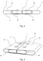
Fig. 3 shows a cross-section view with locations suitable for receiving deformations. -
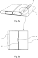
Fig. 4 shows a perspective view of the tube with deformations on one of the main walls. -
Fig. 5a shows a perspective view of the tube with deformations on one of the wall portions. -
Fig 5b shows a top view of the tube ofFig. 5a . - The subject-matter of the invention is a
flat tube 1 for the flow therein of a fluid in a heat exchanger. The heat exchanger may be of any type as long as it is provided with so-called folded tubes.Such tube 1 may be formed by bending asheet metal strip 2 along the length of thestrip 2. The sheet of metal may be for example, aluminum. - The
tube 1 may comprise an outside surface and a layer ofbraze metal 3 thereon. Thebraze material 3 may be, for example, a flux. The flux is a chemical compound applied to the joint surfaces before brazing. Its use, with a few exceptions, is crucial in the atmospheric brazing process. Thebraze material 3 may thus be pre-applied on the corresponding surface ofsaid strip 2 to enhance the quality of the brazing joint. - As shown in
Fig. 1 , thetube 1 may further comprise a firstmain wall 4, a secondmain wall 5 which is substantially parallel with respect to the firstmain wall 4. Themain walls - The
tube 1 may further comprise two complementaryside wall portions 6 joining saidmain walls tube 1.Side wall portions 6 may be substantially arcuate in shape having a desired radius of curvature, but other shapes may be used without departing from the scope of the present invention. -
Fig. 2 shows a detailed view of a main wall of the tube ofFig.1 . It is notable that thebraze material 3 is located on one side of themetal strip 2. This allows brazing all portions together. - As shown in
Fig. 3 saidstrip 2 may define over its width a middle region and two intermediate regions on either side of said middle region. The middle region may comprise two channels for the fluid being separated by amedian wall 7. Themedian wall 7 may divide thetube 1 into two substantially mirror-imaged portions. However, an embodiment in which the median wall is shifted towards either of thewall portions 6, or inclined so that it does not divide thetube 1 into two mirror-image portions, is also envisaged. - The
median wall 7 may be twice the thickness of any of themain walls side wall portions 6. - The first
main wall 4 of thetube 1 may be formed from said middle region. The secondmain wall 5 of thetube 1 may comprise twowall portions - The
median wall 7 extends in the longitudinal direction of thetube 1, i.e. in the axis of elongation of thetube 1, and contacts the first and secondmain walls median wall 7 are preferably substantially perpendicular to themain walls median wall 7 is defined by a double thickness of themetal sheet strip 2 with one part attached to the secondmain wall 5 and is located intermediate theside wall portions 6 and thewall portions wall portions 5A. 5B of the secondmain wall 5 may be juxtaposed in substantially a common plane. - The double thickness of the
metal sheet strip 2 may extend in parallel to the firstmain wall 4 and within the respective middle region to form a firstinner wall 8A and a secondinner wall 8B. The wall portionsinner walls median wall 7 formed by the double thickness of themetal sheet strip 2 towards respectiveside wall portions 6. At least part of eachinner wall main wall 4 and fixed thereto, for example, by brazing. Thebraze material 3 on corresponding side of thesheet metal strip 2 enhances the process of fixation. A respective second pieces of theinner walls main wall 4. The second pieces may project towards the secondmain wall 5 and they may be fixed thereto. Further, the second pieces, similarly to side wall portions, be substantially arcuate in shape having a desired radius of curvature, but other shapes may be used without departing from the scope of the present invention. Substantially, the second pierces of theinner walls main wall 4 so that the terminal end of second pieces face each other and at least portion of each of second pieces is substantially parallel to the secondmain wall 5. Saidinner walls median wall 7 and respective portions of themain walls tube 1. - The
strip 2 may further comprise at least onedeformation 9. Referring toFig.3 , the desired locations of thedeformations 9 are marked with an oval shapes. The deformations allow to locally deviate the surface of any of thewalls 5B deformations 9 allow to increase the rigidity of thetube 1 in desired regions, without using additional elements and without increasing the thickness of the metal sheet strip. Consequently, thetube 1 is able to withstand thermal shock caused by the rapid temperature and/or pressure change of the fluid. Furthermore, thedeformations 9 may increase the overall performance of the heat exchanger by deflecting the path of the fluid flowing through thetube 1, so that the heat exchange may be increased. - The location and the number of the
deformations 9 is not a liming factor, thus they may be allocated according to the desired effects. - For example, at least one
deformation 9 may be disposed on at least one of themain walls deformations 9 may also be located on bothmain walls - Further, at least one
deformation 9 may disposed on at least one ofside wall portions 6. Thedeformations 9 may also be located on bothside wall portions 6. - For example, at least one
deformation 9 may be disposed on at least one of theinner walls deformations 9 may also be located on bothinner walls deformation 9 may be disposed on at least first piece ofinner wall inner wall - Further, at least one
deformation 9 may be disposed on at least one of thewall portions deformations 9 may also be located on bothwall portions - As shown in
Fig. 4 , one or more deformations located on thesame wall set 99. Each set 99 may comprise a random pattern, i.e. one cannot distinguish any rule or conception according to which the deformations are allocated. However, it is more likely that one can distinguish pattern in which theset 99 ofdeformations 9 is allocated onparticular wall - For example, the
deformations 9 may be arranged in series. The distance between eachdeformation 9 of theset 99 may be equal or different or increasing. Thedeformations 9 may thus be equidistant within theset 99, with respect to axis of elongation of thetube 1. - For example, the
deformations 9 may be arranged in zig-zag pattern. The distance between eachdeformation 9 of theset 99 may be equal or different or increasing. - As shown in
Figs 5a and 5b , thedeformation 9 may be in form of protrusion projecting inwardly towards the center of the middle region. In other words, thedeformation 9 may deviate from the surface of theinner wall deformations 9 project from a second piece of theinner wall 8A. - Alternatively, the
deformation 9 may be in form of protrusion projecting outwardly from the center of the middle region. In other words, thedeformation 9 may deviate from the surface of thewall - The
deformations 9 may comprise different shapes and sizes. Thus, the shape or size of thedeformation 9 does not limit the invention to any particular example. - For example, the
deformation 9 may have an oblong shape, or a pyramidal shape, or a trapezoidal shape, or substantially rectangular shape. - Another object of the invention may be a heat exchanger 100 comprising aforementioned
flat tube 1. Theflat tube 1 may provide a fluid communication between the manifolds, thus increasing overall performance thereof. - Other variations to the disclosed embodiments can be understood and effected by those skilled in the art in practicing the claimed invention, from a study of drawings, the disclosure, and the appended claims. The mere fact that certain measures are recited in mutually different dependent claims does not indicate that a combination of these measures cannot be used to the advantage.
Claims (14)
- A flat tube (1) for the flow therein of a fluid in a heat exchanger, the tube (1) being formed by bending a sheet metal strip (2) along the length of the strip, the tube comprising: a first main wall (4); a second main wall (5) parallel to the first main wall (4), said main walls (4, 5) being substantially flat; two complementary side wall portions (6) joining said main walls together so as to define a closed profile of the tube (1), said strip (2) defining over its width a middle region and two intermediate regions on either side of said middle region, the first main wall (4) of the tube (1) being formed from said middle region, said second main wall (5) of the tube (1) comprising two wall portions (5A, 5B) each formed from a respective one of said intermediate regions, with said wall portions (5A. 5B) of the second main wall (5) being juxtaposed in substantially a common plane, a median wall (7) defined by a double thickness of the sheet metal strip (2) with one part attached to a first wall portion (5A) and the other part attached to a second wall portion (5B), and inner walls (8A, 8B) each formed from a respective one of said parts of the median wall (7), wherein a first piece of said inner wall is at least partially fixed and parallel to the first main wall (4), and a second piece of said inner wall is joining the main walls (4,5) within the middle region of the tube (1), wherein the sheet metal strip (2) further comprises at least one deformation (9) configured to locally deviate the surface of any of the walls (4,5,6, 5A, 5B).
- The flat tube (1) according to claim 1, wherein at least one deformation (9) is disposed on at least one main wall (4,5).
- The flat tube (1) according to any of the preceding claims, wherein at least one deformation (9) is disposed on at least one of side wall portions (6).
- The flat tube (1) according to any of the preceding claims, wherein at least one deformation (9) is disposed on at least one of the inner walls (8A, 8B).
- The flat tube (1) according to any of the preceding claims, wherein the deformation (9) is in form of protrusion projecting inwardly towards the center of the intermediate region.
- The flat tube (1) according to any of the preceding claims, wherein the deformation (9) is in form of protrusion projecting outwardly from the center of the intermediate region.
- The flat tube (1) according to any of the preceding claims wherein the strip (2) comprises at least one set (99) of deformations (9), wherein the set (99) is limited by the walls (4,5,6 8A, 8B).
- The flat tube (1) according to claim 7, wherein the deformations (9) are equidistant within the set (99), with respect to axis of elongation of the tube (1).
- The flat tube (1) according to claim 7, wherein the distance between consecutive deformations (9) forming the set (99) are different.
- The flat tube (1) according to any of the preceding claims, wherein the deformation (9) has an oblong shape.
- The flat tube (1) according to any of the preceding claims, wherein the deformation (9) has a pyramidal shape.
- The flat tube (1) according to any of the preceding claims, wherein the deformation (9) has a substantially rectangular shape.
- The tube (1) according to any of the preceding claims, wherein the sheet metal strip (2) comprises an outside surface and a layer of braze metal (3) on said outside surface, said layer having been pre-applied on the corresponding surface of said strip (2).
- A heat exchanger (100) comprising at least one flat tube (1) according to claims 1-12.
Priority Applications (2)
| Application Number | Priority Date | Filing Date | Title |
|---|---|---|---|
| EP22151651.1A EP4212811B1 (en) | 2022-01-14 | 2022-01-14 | A flat tube |
| PCT/EP2022/086344 WO2023134960A1 (en) | 2022-01-14 | 2022-12-16 | A flat tube |
Applications Claiming Priority (1)
| Application Number | Priority Date | Filing Date | Title |
|---|---|---|---|
| EP22151651.1A EP4212811B1 (en) | 2022-01-14 | 2022-01-14 | A flat tube |
Publications (2)
| Publication Number | Publication Date |
|---|---|
| EP4212811A1 true EP4212811A1 (en) | 2023-07-19 |
| EP4212811B1 EP4212811B1 (en) | 2025-04-16 |
Family
ID=80112251
Family Applications (1)
| Application Number | Title | Priority Date | Filing Date |
|---|---|---|---|
| EP22151651.1A Active EP4212811B1 (en) | 2022-01-14 | 2022-01-14 | A flat tube |
Country Status (2)
| Country | Link |
|---|---|
| EP (1) | EP4212811B1 (en) |
| WO (1) | WO2023134960A1 (en) |
Citations (4)
| Publication number | Priority date | Publication date | Assignee | Title |
|---|---|---|---|---|
| US20060201665A1 (en) * | 2005-03-09 | 2006-09-14 | Visteon Global Technologies, Inc. | Heat exchanger tube having strengthening deformations |
| EP1712862A2 (en) * | 2005-04-13 | 2006-10-18 | Delphi Technologies, Inc. | Fabricated, brazed metal heat exchanger tube manufacture |
| GB2509762A (en) * | 2013-01-14 | 2014-07-16 | Halla Visteon Climate Control | Tube for a heat exchanger |
| US20180106556A1 (en) * | 2016-10-14 | 2018-04-19 | Hanon Systems | B-tube reform for improved thermal cycle performance |
-
2022
- 2022-01-14 EP EP22151651.1A patent/EP4212811B1/en active Active
- 2022-12-16 WO PCT/EP2022/086344 patent/WO2023134960A1/en not_active Ceased
Patent Citations (4)
| Publication number | Priority date | Publication date | Assignee | Title |
|---|---|---|---|---|
| US20060201665A1 (en) * | 2005-03-09 | 2006-09-14 | Visteon Global Technologies, Inc. | Heat exchanger tube having strengthening deformations |
| EP1712862A2 (en) * | 2005-04-13 | 2006-10-18 | Delphi Technologies, Inc. | Fabricated, brazed metal heat exchanger tube manufacture |
| GB2509762A (en) * | 2013-01-14 | 2014-07-16 | Halla Visteon Climate Control | Tube for a heat exchanger |
| US20180106556A1 (en) * | 2016-10-14 | 2018-04-19 | Hanon Systems | B-tube reform for improved thermal cycle performance |
Also Published As
| Publication number | Publication date |
|---|---|
| EP4212811B1 (en) | 2025-04-16 |
| WO2023134960A1 (en) | 2023-07-20 |
Similar Documents
| Publication | Publication Date | Title |
|---|---|---|
| JP4724594B2 (en) | Heat exchanger | |
| US7117936B2 (en) | Tube for heat exchanger | |
| US7775067B2 (en) | Heat exchanger header tank and heat exchanger comprising same | |
| JP2005326135A (en) | Heat exchanger | |
| JP4171760B2 (en) | Flat tube and manufacturing method of flat tube | |
| JP4724433B2 (en) | Heat exchanger | |
| US20160054075A1 (en) | Folded tube multiple bank heat exchange unit | |
| KR19980032970A (en) | evaporator | |
| JP4972488B2 (en) | Heat exchanger | |
| JP2001050677A (en) | Heat exchanger | |
| JP2007147172A (en) | Heat exchanger | |
| EP4212811A1 (en) | A flat tube | |
| CN110595248B (en) | Flat pipe, heat exchange pipe, heat exchanger and manufacturing method of heat exchange pipe | |
| JP2006078163A (en) | Flat tube, plate body for manufacturing flat tube, and heat exchanger | |
| EP0853227A2 (en) | Heat exchanger | |
| JP4898672B2 (en) | Heat exchanger | |
| JP2009113625A (en) | Evaporator | |
| JP2009180394A (en) | Heat exchanger | |
| JP2010107147A (en) | Heat exchanger and method of manufacturing the same | |
| JP2010038378A (en) | Heat exchanger | |
| JP2007032952A (en) | Header tank for heat exchanger, and heat exchanger using the same | |
| JPH10185358A (en) | Evaporator | |
| JPH06159969A (en) | Stacked condenser | |
| JP2007147173A (en) | Heat exchanger and its manufacturing method | |
| EP4491992A1 (en) | A flat tube |
Legal Events
| Date | Code | Title | Description |
|---|---|---|---|
| PUAI | Public reference made under article 153(3) epc to a published international application that has entered the european phase |
Free format text: ORIGINAL CODE: 0009012 |
|
| STAA | Information on the status of an ep patent application or granted ep patent |
Free format text: STATUS: THE APPLICATION HAS BEEN PUBLISHED |
|
| AK | Designated contracting states |
Kind code of ref document: A1 Designated state(s): AL AT BE BG CH CY CZ DE DK EE ES FI FR GB GR HR HU IE IS IT LI LT LU LV MC MK MT NL NO PL PT RO RS SE SI SK SM TR |
|
| STAA | Information on the status of an ep patent application or granted ep patent |
Free format text: STATUS: REQUEST FOR EXAMINATION WAS MADE |
|
| 17P | Request for examination filed |
Effective date: 20240118 |
|
| RBV | Designated contracting states (corrected) |
Designated state(s): AL AT BE BG CH CY CZ DE DK EE ES FI FR GB GR HR HU IE IS IT LI LT LU LV MC MK MT NL NO PL PT RO RS SE SI SK SM TR |
|
| GRAP | Despatch of communication of intention to grant a patent |
Free format text: ORIGINAL CODE: EPIDOSNIGR1 |
|
| STAA | Information on the status of an ep patent application or granted ep patent |
Free format text: STATUS: GRANT OF PATENT IS INTENDED |
|
| RAP3 | Party data changed (applicant data changed or rights of an application transferred) |
Owner name: VALEO AUTOSYSTEMY SP. Z O.O. |
|
| INTG | Intention to grant announced |
Effective date: 20240821 |
|
| GRAS | Grant fee paid |
Free format text: ORIGINAL CODE: EPIDOSNIGR3 |
|
| GRAA | (expected) grant |
Free format text: ORIGINAL CODE: 0009210 |
|
| STAA | Information on the status of an ep patent application or granted ep patent |
Free format text: STATUS: THE PATENT HAS BEEN GRANTED |
|
| AK | Designated contracting states |
Kind code of ref document: B1 Designated state(s): AL AT BE BG CH CY CZ DE DK EE ES FI FR GB GR HR HU IE IS IT LI LT LU LV MC MK MT NL NO PL PT RO RS SE SI SK SM TR |
|
| REG | Reference to a national code |
Ref country code: GB Ref legal event code: FG4D |
|
| REG | Reference to a national code |
Ref country code: CH Ref legal event code: EP Ref country code: DE Ref legal event code: R096 Ref document number: 602022013078 Country of ref document: DE |
|
| REG | Reference to a national code |
Ref country code: IE Ref legal event code: FG4D |
|
| REG | Reference to a national code |
Ref country code: NL Ref legal event code: MP Effective date: 20250416 |
|
| PG25 | Lapsed in a contracting state [announced via postgrant information from national office to epo] |
Ref country code: NL Free format text: LAPSE BECAUSE OF FAILURE TO SUBMIT A TRANSLATION OF THE DESCRIPTION OR TO PAY THE FEE WITHIN THE PRESCRIBED TIME-LIMIT Effective date: 20250416 |
|
| REG | Reference to a national code |
Ref country code: AT Ref legal event code: MK05 Ref document number: 1785937 Country of ref document: AT Kind code of ref document: T Effective date: 20250416 |
|
| PG25 | Lapsed in a contracting state [announced via postgrant information from national office to epo] |
Ref country code: FI Free format text: LAPSE BECAUSE OF FAILURE TO SUBMIT A TRANSLATION OF THE DESCRIPTION OR TO PAY THE FEE WITHIN THE PRESCRIBED TIME-LIMIT Effective date: 20250416 Ref country code: ES Free format text: LAPSE BECAUSE OF FAILURE TO SUBMIT A TRANSLATION OF THE DESCRIPTION OR TO PAY THE FEE WITHIN THE PRESCRIBED TIME-LIMIT Effective date: 20250416 Ref country code: PT Free format text: LAPSE BECAUSE OF FAILURE TO SUBMIT A TRANSLATION OF THE DESCRIPTION OR TO PAY THE FEE WITHIN THE PRESCRIBED TIME-LIMIT Effective date: 20250818 |
|
| REG | Reference to a national code |
Ref country code: LT Ref legal event code: MG9D |
|
| PG25 | Lapsed in a contracting state [announced via postgrant information from national office to epo] |
Ref country code: GR Free format text: LAPSE BECAUSE OF FAILURE TO SUBMIT A TRANSLATION OF THE DESCRIPTION OR TO PAY THE FEE WITHIN THE PRESCRIBED TIME-LIMIT Effective date: 20250717 Ref country code: NO Free format text: LAPSE BECAUSE OF FAILURE TO SUBMIT A TRANSLATION OF THE DESCRIPTION OR TO PAY THE FEE WITHIN THE PRESCRIBED TIME-LIMIT Effective date: 20250716 |
|
| PG25 | Lapsed in a contracting state [announced via postgrant information from national office to epo] |
Ref country code: PL Free format text: LAPSE BECAUSE OF FAILURE TO SUBMIT A TRANSLATION OF THE DESCRIPTION OR TO PAY THE FEE WITHIN THE PRESCRIBED TIME-LIMIT Effective date: 20250416 |
|
| PG25 | Lapsed in a contracting state [announced via postgrant information from national office to epo] |
Ref country code: BG Free format text: LAPSE BECAUSE OF FAILURE TO SUBMIT A TRANSLATION OF THE DESCRIPTION OR TO PAY THE FEE WITHIN THE PRESCRIBED TIME-LIMIT Effective date: 20250416 |
|
| PG25 | Lapsed in a contracting state [announced via postgrant information from national office to epo] |
Ref country code: HR Free format text: LAPSE BECAUSE OF FAILURE TO SUBMIT A TRANSLATION OF THE DESCRIPTION OR TO PAY THE FEE WITHIN THE PRESCRIBED TIME-LIMIT Effective date: 20250416 |
|
| PG25 | Lapsed in a contracting state [announced via postgrant information from national office to epo] |
Ref country code: AT Free format text: LAPSE BECAUSE OF FAILURE TO SUBMIT A TRANSLATION OF THE DESCRIPTION OR TO PAY THE FEE WITHIN THE PRESCRIBED TIME-LIMIT Effective date: 20250416 |
|
| PG25 | Lapsed in a contracting state [announced via postgrant information from national office to epo] |
Ref country code: RS Free format text: LAPSE BECAUSE OF FAILURE TO SUBMIT A TRANSLATION OF THE DESCRIPTION OR TO PAY THE FEE WITHIN THE PRESCRIBED TIME-LIMIT Effective date: 20250716 |
|
| PG25 | Lapsed in a contracting state [announced via postgrant information from national office to epo] |
Ref country code: IS Free format text: LAPSE BECAUSE OF FAILURE TO SUBMIT A TRANSLATION OF THE DESCRIPTION OR TO PAY THE FEE WITHIN THE PRESCRIBED TIME-LIMIT Effective date: 20250816 |
|
| PG25 | Lapsed in a contracting state [announced via postgrant information from national office to epo] |
Ref country code: LV Free format text: LAPSE BECAUSE OF FAILURE TO SUBMIT A TRANSLATION OF THE DESCRIPTION OR TO PAY THE FEE WITHIN THE PRESCRIBED TIME-LIMIT Effective date: 20250416 |
|
| PG25 | Lapsed in a contracting state [announced via postgrant information from national office to epo] |
Ref country code: DK Free format text: LAPSE BECAUSE OF FAILURE TO SUBMIT A TRANSLATION OF THE DESCRIPTION OR TO PAY THE FEE WITHIN THE PRESCRIBED TIME-LIMIT Effective date: 20250416 Ref country code: SM Free format text: LAPSE BECAUSE OF FAILURE TO SUBMIT A TRANSLATION OF THE DESCRIPTION OR TO PAY THE FEE WITHIN THE PRESCRIBED TIME-LIMIT Effective date: 20250416 |
|
| REG | Reference to a national code |
Ref country code: DE Ref legal event code: R097 Ref document number: 602022013078 Country of ref document: DE |
|
| PG25 | Lapsed in a contracting state [announced via postgrant information from national office to epo] |
Ref country code: CZ Free format text: LAPSE BECAUSE OF FAILURE TO SUBMIT A TRANSLATION OF THE DESCRIPTION OR TO PAY THE FEE WITHIN THE PRESCRIBED TIME-LIMIT Effective date: 20250416 |
|
| PG25 | Lapsed in a contracting state [announced via postgrant information from national office to epo] |
Ref country code: EE Free format text: LAPSE BECAUSE OF FAILURE TO SUBMIT A TRANSLATION OF THE DESCRIPTION OR TO PAY THE FEE WITHIN THE PRESCRIBED TIME-LIMIT Effective date: 20250416 |
|
| PG25 | Lapsed in a contracting state [announced via postgrant information from national office to epo] |
Ref country code: SK Free format text: LAPSE BECAUSE OF FAILURE TO SUBMIT A TRANSLATION OF THE DESCRIPTION OR TO PAY THE FEE WITHIN THE PRESCRIBED TIME-LIMIT Effective date: 20250416 |
|
| PG25 | Lapsed in a contracting state [announced via postgrant information from national office to epo] |
Ref country code: IT Free format text: LAPSE BECAUSE OF FAILURE TO SUBMIT A TRANSLATION OF THE DESCRIPTION OR TO PAY THE FEE WITHIN THE PRESCRIBED TIME-LIMIT Effective date: 20250416 |
|
| PLBE | No opposition filed within time limit |
Free format text: ORIGINAL CODE: 0009261 |
|
| STAA | Information on the status of an ep patent application or granted ep patent |
Free format text: STATUS: NO OPPOSITION FILED WITHIN TIME LIMIT |
|
| REG | Reference to a national code |
Ref country code: CH Ref legal event code: L10 Free format text: ST27 STATUS EVENT CODE: U-0-0-L10-L00 (AS PROVIDED BY THE NATIONAL OFFICE) Effective date: 20260225 |
|
| 26N | No opposition filed |
Effective date: 20260119 |
|
| PGFP | Annual fee paid to national office [announced via postgrant information from national office to epo] |
Ref country code: DE Payment date: 20260114 Year of fee payment: 5 |
|
| PGFP | Annual fee paid to national office [announced via postgrant information from national office to epo] |
Ref country code: FR Payment date: 20260128 Year of fee payment: 5 |