EP4212712A1 - An internal combustion engine and a method for controlling a braking torque of the engine - Google Patents
An internal combustion engine and a method for controlling a braking torque of the engine Download PDFInfo
- Publication number
- EP4212712A1 EP4212712A1 EP23155713.3A EP23155713A EP4212712A1 EP 4212712 A1 EP4212712 A1 EP 4212712A1 EP 23155713 A EP23155713 A EP 23155713A EP 4212712 A1 EP4212712 A1 EP 4212712A1
- Authority
- EP
- European Patent Office
- Prior art keywords
- engine
- flow
- guide
- exhaust
- cylinder
- Prior art date
- Legal status (The legal status is an assumption and is not a legal conclusion. Google has not performed a legal analysis and makes no representation as to the accuracy of the status listed.)
- Pending
Links
Images




Classifications
-
- F—MECHANICAL ENGINEERING; LIGHTING; HEATING; WEAPONS; BLASTING
- F02—COMBUSTION ENGINES; HOT-GAS OR COMBUSTION-PRODUCT ENGINE PLANTS
- F02D—CONTROLLING COMBUSTION ENGINES
- F02D13/00—Controlling the engine output power by varying inlet or exhaust valve operating characteristics, e.g. timing
- F02D13/02—Controlling the engine output power by varying inlet or exhaust valve operating characteristics, e.g. timing during engine operation
- F02D13/04—Controlling the engine output power by varying inlet or exhaust valve operating characteristics, e.g. timing during engine operation using engine as brake
-
- F—MECHANICAL ENGINEERING; LIGHTING; HEATING; WEAPONS; BLASTING
- F01—MACHINES OR ENGINES IN GENERAL; ENGINE PLANTS IN GENERAL; STEAM ENGINES
- F01L—CYCLICALLY OPERATING VALVES FOR MACHINES OR ENGINES
- F01L1/00—Valve-gear or valve arrangements, e.g. lift-valve gear
- F01L1/02—Valve drive
- F01L1/04—Valve drive by means of cams, camshafts, cam discs, eccentrics or the like
- F01L1/08—Shape of cams
-
- F—MECHANICAL ENGINEERING; LIGHTING; HEATING; WEAPONS; BLASTING
- F01—MACHINES OR ENGINES IN GENERAL; ENGINE PLANTS IN GENERAL; STEAM ENGINES
- F01L—CYCLICALLY OPERATING VALVES FOR MACHINES OR ENGINES
- F01L1/00—Valve-gear or valve arrangements, e.g. lift-valve gear
- F01L1/12—Transmitting gear between valve drive and valve
- F01L1/18—Rocking arms or levers
- F01L1/181—Centre pivot rocking arms
-
- F—MECHANICAL ENGINEERING; LIGHTING; HEATING; WEAPONS; BLASTING
- F01—MACHINES OR ENGINES IN GENERAL; ENGINE PLANTS IN GENERAL; STEAM ENGINES
- F01L—CYCLICALLY OPERATING VALVES FOR MACHINES OR ENGINES
- F01L13/00—Modifications of valve-gear to facilitate reversing, braking, starting, changing compression ratio, or other specific operations
- F01L13/06—Modifications of valve-gear to facilitate reversing, braking, starting, changing compression ratio, or other specific operations for braking
- F01L13/065—Compression release engine retarders of the "Jacobs Manufacturing" type
-
- F—MECHANICAL ENGINEERING; LIGHTING; HEATING; WEAPONS; BLASTING
- F02—COMBUSTION ENGINES; HOT-GAS OR COMBUSTION-PRODUCT ENGINE PLANTS
- F02D—CONTROLLING COMBUSTION ENGINES
- F02D13/00—Controlling the engine output power by varying inlet or exhaust valve operating characteristics, e.g. timing
- F02D13/02—Controlling the engine output power by varying inlet or exhaust valve operating characteristics, e.g. timing during engine operation
- F02D13/0242—Variable control of the exhaust valves only
- F02D13/0249—Variable control of the exhaust valves only changing the valve timing only
-
- F—MECHANICAL ENGINEERING; LIGHTING; HEATING; WEAPONS; BLASTING
- F02—COMBUSTION ENGINES; HOT-GAS OR COMBUSTION-PRODUCT ENGINE PLANTS
- F02D—CONTROLLING COMBUSTION ENGINES
- F02D41/00—Electrical control of supply of combustible mixture or its constituents
- F02D41/0002—Controlling intake air
- F02D41/0007—Controlling intake air for control of turbo-charged or super-charged engines
-
- F—MECHANICAL ENGINEERING; LIGHTING; HEATING; WEAPONS; BLASTING
- F02—COMBUSTION ENGINES; HOT-GAS OR COMBUSTION-PRODUCT ENGINE PLANTS
- F02D—CONTROLLING COMBUSTION ENGINES
- F02D41/00—Electrical control of supply of combustible mixture or its constituents
- F02D41/02—Circuit arrangements for generating control signals
- F02D41/04—Introducing corrections for particular operating conditions
- F02D41/12—Introducing corrections for particular operating conditions for deceleration
-
- F—MECHANICAL ENGINEERING; LIGHTING; HEATING; WEAPONS; BLASTING
- F02—COMBUSTION ENGINES; HOT-GAS OR COMBUSTION-PRODUCT ENGINE PLANTS
- F02D—CONTROLLING COMBUSTION ENGINES
- F02D9/00—Controlling engines by throttling air or fuel-and-air induction conduits or exhaust conduits
- F02D9/02—Controlling engines by throttling air or fuel-and-air induction conduits or exhaust conduits concerning induction conduits
-
- F—MECHANICAL ENGINEERING; LIGHTING; HEATING; WEAPONS; BLASTING
- F02—COMBUSTION ENGINES; HOT-GAS OR COMBUSTION-PRODUCT ENGINE PLANTS
- F02D—CONTROLLING COMBUSTION ENGINES
- F02D9/00—Controlling engines by throttling air or fuel-and-air induction conduits or exhaust conduits
- F02D9/04—Controlling engines by throttling air or fuel-and-air induction conduits or exhaust conduits concerning exhaust conduits
- F02D9/06—Exhaust brakes
-
- F—MECHANICAL ENGINEERING; LIGHTING; HEATING; WEAPONS; BLASTING
- F01—MACHINES OR ENGINES IN GENERAL; ENGINE PLANTS IN GENERAL; STEAM ENGINES
- F01L—CYCLICALLY OPERATING VALVES FOR MACHINES OR ENGINES
- F01L1/00—Valve-gear or valve arrangements, e.g. lift-valve gear
- F01L1/34—Valve-gear or valve arrangements, e.g. lift-valve gear characterised by the provision of means for changing the timing of the valves without changing the duration of opening and without affecting the magnitude of the valve lift
-
- F—MECHANICAL ENGINEERING; LIGHTING; HEATING; WEAPONS; BLASTING
- F01—MACHINES OR ENGINES IN GENERAL; ENGINE PLANTS IN GENERAL; STEAM ENGINES
- F01L—CYCLICALLY OPERATING VALVES FOR MACHINES OR ENGINES
- F01L13/00—Modifications of valve-gear to facilitate reversing, braking, starting, changing compression ratio, or other specific operations
- F01L2013/10—Auxiliary actuators for variable valve timing
- F01L2013/105—Hydraulic motors
-
- F—MECHANICAL ENGINEERING; LIGHTING; HEATING; WEAPONS; BLASTING
- F01—MACHINES OR ENGINES IN GENERAL; ENGINE PLANTS IN GENERAL; STEAM ENGINES
- F01L—CYCLICALLY OPERATING VALVES FOR MACHINES OR ENGINES
- F01L2305/00—Valve arrangements comprising rollers
-
- F—MECHANICAL ENGINEERING; LIGHTING; HEATING; WEAPONS; BLASTING
- F01—MACHINES OR ENGINES IN GENERAL; ENGINE PLANTS IN GENERAL; STEAM ENGINES
- F01L—CYCLICALLY OPERATING VALVES FOR MACHINES OR ENGINES
- F01L2800/00—Methods of operation using a variable valve timing mechanism
-
- F—MECHANICAL ENGINEERING; LIGHTING; HEATING; WEAPONS; BLASTING
- F01—MACHINES OR ENGINES IN GENERAL; ENGINE PLANTS IN GENERAL; STEAM ENGINES
- F01N—GAS-FLOW SILENCERS OR EXHAUST APPARATUS FOR MACHINES OR ENGINES IN GENERAL; GAS-FLOW SILENCERS OR EXHAUST APPARATUS FOR INTERNAL-COMBUSTION ENGINES
- F01N13/00—Exhaust or silencing apparatus characterised by constructional features
- F01N13/08—Other arrangements or adaptations of exhaust conduits
- F01N13/10—Other arrangements or adaptations of exhaust conduits of exhaust manifolds
- F01N13/107—More than one exhaust manifold or exhaust collector
-
- F—MECHANICAL ENGINEERING; LIGHTING; HEATING; WEAPONS; BLASTING
- F01—MACHINES OR ENGINES IN GENERAL; ENGINE PLANTS IN GENERAL; STEAM ENGINES
- F01N—GAS-FLOW SILENCERS OR EXHAUST APPARATUS FOR MACHINES OR ENGINES IN GENERAL; GAS-FLOW SILENCERS OR EXHAUST APPARATUS FOR INTERNAL-COMBUSTION ENGINES
- F01N2240/00—Combination or association of two or more different exhaust treating devices, or of at least one such device with an auxiliary device, not covered by indexing codes F01N2230/00 or F01N2250/00, one of the devices being
- F01N2240/36—Combination or association of two or more different exhaust treating devices, or of at least one such device with an auxiliary device, not covered by indexing codes F01N2230/00 or F01N2250/00, one of the devices being an exhaust flap
-
- F—MECHANICAL ENGINEERING; LIGHTING; HEATING; WEAPONS; BLASTING
- F01—MACHINES OR ENGINES IN GENERAL; ENGINE PLANTS IN GENERAL; STEAM ENGINES
- F01N—GAS-FLOW SILENCERS OR EXHAUST APPARATUS FOR MACHINES OR ENGINES IN GENERAL; GAS-FLOW SILENCERS OR EXHAUST APPARATUS FOR INTERNAL-COMBUSTION ENGINES
- F01N2590/00—Exhaust or silencing apparatus adapted to particular use, e.g. for military applications, airplanes, submarines
- F01N2590/08—Exhaust or silencing apparatus adapted to particular use, e.g. for military applications, airplanes, submarines for heavy duty applications, e.g. trucks, buses, tractors, locomotives
-
- F—MECHANICAL ENGINEERING; LIGHTING; HEATING; WEAPONS; BLASTING
- F02—COMBUSTION ENGINES; HOT-GAS OR COMBUSTION-PRODUCT ENGINE PLANTS
- F02D—CONTROLLING COMBUSTION ENGINES
- F02D9/00—Controlling engines by throttling air or fuel-and-air induction conduits or exhaust conduits
- F02D9/02—Controlling engines by throttling air or fuel-and-air induction conduits or exhaust conduits concerning induction conduits
- F02D2009/0201—Arrangements; Control features; Details thereof
- F02D2009/0242—Increasing exhaust brake effect
-
- F—MECHANICAL ENGINEERING; LIGHTING; HEATING; WEAPONS; BLASTING
- F02—COMBUSTION ENGINES; HOT-GAS OR COMBUSTION-PRODUCT ENGINE PLANTS
- F02D—CONTROLLING COMBUSTION ENGINES
- F02D2200/00—Input parameters for engine control
- F02D2200/02—Input parameters for engine control the parameters being related to the engine
- F02D2200/10—Parameters related to the engine output, e.g. engine torque or engine speed
- F02D2200/101—Engine speed
-
- F—MECHANICAL ENGINEERING; LIGHTING; HEATING; WEAPONS; BLASTING
- F02—COMBUSTION ENGINES; HOT-GAS OR COMBUSTION-PRODUCT ENGINE PLANTS
- F02D—CONTROLLING COMBUSTION ENGINES
- F02D2700/00—Mechanical control of speed or power of a single cylinder piston engine
- F02D2700/04—Controlling by throttling the exhaust conduit
-
- Y—GENERAL TAGGING OF NEW TECHNOLOGICAL DEVELOPMENTS; GENERAL TAGGING OF CROSS-SECTIONAL TECHNOLOGIES SPANNING OVER SEVERAL SECTIONS OF THE IPC; TECHNICAL SUBJECTS COVERED BY FORMER USPC CROSS-REFERENCE ART COLLECTIONS [XRACs] AND DIGESTS
- Y02—TECHNOLOGIES OR APPLICATIONS FOR MITIGATION OR ADAPTATION AGAINST CLIMATE CHANGE
- Y02T—CLIMATE CHANGE MITIGATION TECHNOLOGIES RELATED TO TRANSPORTATION
- Y02T10/00—Road transport of goods or passengers
- Y02T10/10—Internal combustion engine [ICE] based vehicles
- Y02T10/12—Improving ICE efficiencies
Definitions
- the air guide pressure in the air guide downstream of a compressor of the turbocharger may be indicative of the turbocharger rotational speed
- the air guide pressure is dependent also on other parameters. Therefore, it is usually not possible to use the air guide pressure as an indicator of the turbocharger rotational speed with any high degree of accuracy.
- adjusting the restriction of the flow through the air guide in dependence on the air guide pressure requires a safety margin to secure that the turbocharger rotational speed limit is not exceeded.
- the invention allows for an operation without such a limit, and therefore, the engine braking performance can be increased.
- the method may comprise adjusting the restriction of the flow through the exhaust guide in dependence on one or more of the engine rotational speed, a requested engine braking torque, and a current engine braking torque.
- the adjustment of the restriction of the flow through the exhaust guide is advantageously done in an open loop adjustment.
- an algorithm which is simple to implement, is provided to obtain an exhaust guide back pressure and a coarse setting of the engine brake power level, and a continuous closed loop adjustment, in dependence on the turbocharger rotational speed value, of the restriction of the flow through the air guide may fine tune the cylinder air mass-flow and the cylinder pressure, to closely adjust the engine braking power.
- the exhaust guide may be arranged to guide the gas flow from the cylinder to a turbine of the turbocharger, wherein the adjustable exhaust flow restriction element is arranged between the cylinder and the turbine.
- Restricting the flow through the exhaust guide may comprise adjusting a throttle valve in the exhaust guide.
- restricting the flow through the exhaust guide may comprise adjusting a flow adjustment function at the turbocharger turbine, where the turbocharger is a variable geometry turbocharger.
- the engine parameter may be one of, or a parameter which is dependent on one or more of, a rotational speed of a turbocharger of the engine, a pressure in the exhaust guide, and a pressure in the air guide. In some embodiments, the engine parameter may be a difference between a pressure in the air guide, and a pressure in the exhaust guide.
- the method comprises adjusting the restriction of the flow through the air guide in dependence on one or more of the engine rotational speed, a requested engine braking torque, and a current engine braking torque.
- the adjustment of the restriction of the flow through the air guide is advantageously done in an open loop adjustment.
- a simple algorithm is provided, in particular for relatively low engine speeds, to obtain, by the air guide flow restriction adjustment, a coarse setting of the engine brake power level, and a continuous closed loop adjustment of the exhaust guide flow restriction, for closely adjusting the engine braking power.
- the exhaust flow restriction element, the exhaust valve, and the exhaust valve actuation assembly may be adapted to provide a backpressure for the engine to provide a braking torque, and the air flow restriction element may be adapted to enable controllability of said braking torque.
- the exhaust flow restriction element, the exhaust valve and the exhaust valve actuation assembly may allow a high maximum braking torque at a wide engine speed interval, while the air flow restriction element allows a high degree of control of the braking torque at a partial load operation.
- the engine may be adapted to run with a Diesel cycle, or adapted to run with an Otto cycle.
- the engine may have one or more cylinders. It is understood that in some embodiments with a multi cylinder engine, a single air guide may be arranged to guide air to all cylinders of the engine, wherein a single air flow restriction element is provided to adjustably provide a restriction of the air flow.
- the engine may be provided with two air guides, each guiding an air flow to a respective cylinder, or a respective sub-group of cylinders, and each being provided with a respective air flow restriction element.
- the exhaust flow restriction element is arranged to provide a plurality of levels of the exhaust flow restriction depending on the adjustment of the exhaust flow restriction element.
- the exhaust flow restriction element is adapted to provide the restriction of the exhaust flow restriction element at any level within a non-zero restriction interval.
- a single exhaust guide may be arranged to guide exhaust gases from all cylinders of the engine.
- a single exhaust flow restriction element 601 may be provided downstream of the turbine of the turbocharger.
- the turbocharger 4 may be a variable geometry turbocharger, whereby the turbocharger 4 provides, with a flow adjusting function at the turbine 401, the function of the exhaust flow restriction element 601 as described herein.
- a fuel system 330 is provided to inject fuel into the cylinders during cycles thereof, and the fuel injection is controllable by the control unit 21.
- the fuel system comprises injectors arranged to inject fuel directly into the cylinders.
- the fuel system may have port injection.
- the selective engagement of the decompression nose 805 and the charge nose 806 is provided by a hydraulic piston 808 at an end of the rocker arm 807 opposite to the end at which the rocker arm 807 is in contact with the cam lobe 803.
- the hydraulic piston 808 is controlled by a hydraulic conduit system and a control valve 809 in each rocker arm 807, each control valve 809 being controllable by the control unit 21.
- the method also comprises determining S3 the requested engine torque and the engine rotational speed.
- the control unit 21 determines by means of the data in the data storage unit 213 a setting for the first and second exhaust flow restriction elements 601, 602 based on the determined values of the engine torque and the engine rotational speed.
- the exhaust flow restriction elements 601, 602 are adjusted S4 to the determined setting, so as to provide a restriction of the air flows in the exhaust guides 501, 502 correlated with the determined requested engine torque and engine rotational speed.
- This adjustment is an open loop adjustment, i.e. although it is updated based on changes in the requested engine torque and engine rotational speed, it is not updated with feedback from any parameter from which the air flow through the cylinders or the cylinder pressure may be determined.
- the control unit 21 also determines, based on the requested engine torque and the engine rotational speed, by means of the data in the data storage unit 213, a setting for the camshaft phase. In an open loop control, the control unit 21 sends signals to the variator 802 so as to adjust S4 the phase of the camshaft rotation to adjust the crankshaft angles of the exhaust valve actuation sequences MOS1, DOS1, COS1. Retarding the commencement of the exhaust valve actuation sequences MOS1, DOS1, COS1 will reduce the pressure in the air guide 901 which will reduce the braking torque, and vice versa.
- Fig. 7 shows a method of controlling the engine 1 in fig. 2 , according to a further embodiment of the invention.
- the method comprises controlling the engine to provide a braking torque.
- This control comprises terminating S1 the supply of fuel to the cylinders 301, 302, restricting S4 the flow through the exhaust guides 501, 502, and restricting S6 the flow through the air guide 901.
- the control of the engine to provide a braking torque also comprises determining S5 a value of a rotational speed of the turbocharger 4, and adjusting S6, in dependence on the determined turbocharger rotational speed value, the restriction of the flow through the air guide 901, and/or the restriction of the flow through the exhaust guide 501, 502.
Landscapes
- Engineering & Computer Science (AREA)
- Mechanical Engineering (AREA)
- General Engineering & Computer Science (AREA)
- Chemical & Material Sciences (AREA)
- Combustion & Propulsion (AREA)
- Output Control And Ontrol Of Special Type Engine (AREA)
- Supercharger (AREA)
Abstract
- controlling the engine to provide a braking torque, the control comprising,
- terminating (S1) the supply of fuel to the cylinder (301, 302),
- restricting (S4) the flow through the exhaust guide (501, 502), and
- restricting (S6) the flow through the air guide (901),
- wherein the control of the engine to provide a braking torque also comprises
- determining (S5) a value of a rotational speed of a turbocharger (4) of the engine, and
- adjusting (S6), in dependence on the determined turbocharger rotational speed value, the restriction of the flow through the air guide (901), and/or the restriction of the flow through the exhaust guide (501, 502).
Description
- The invention relates to a method for controlling an internal combustion engine, a computer program, a computer readable medium, and a control unit.
- The invention can be applied in heavy-duty vehicles, such as trucks, buses and construction equipment. Although the invention will be described with respect to a heavy- duty vehicle, the invention is not restricted to this particular vehicle, but may also be used in other vehicles such as a car.
- It may be desirable to provide, in particular in heavy-duty vehicles, a powerful engine braking function, e.g. in long downhill road stretches with heavy loads.
US5146890A describes an engine with a throttling device in the exhaust system so as to increase the back-pressure therein.US5146890A also describes the provision of exhaust valve opening sequences at the beginning and the end of the compression stroke so as to provide a pressure charge in the cylinder and to avoid a push-back effect at the end of the compression stroke, respectively. - However, during the engine braking operation, there may be changes in the circumstances which reduce the braking power, or which entail risks of damaging the engine due to design limits being exceeded. Although the solution in
US5146890A provides an advantageous increment of the engine braking power, design limits require relatively large margins for the braking operation which impede maximization of the braking power. -
US2012017869A1 describes a system with a throttle in the exhaust system. The back- pressure causes an intermediate opening of the cylinder outlet valves and a rocker arm mechanism keeps the valve open until the exhaust valve main opening sequence occurs. This is disadvantageous since the exhaust valves are open during the entire compression stroke, whereby engine braking power is lost. Also, there is similarly to the solution in -
US5146890A a disadvantageous need to consider design limits which require relatively large margins for the braking operation which impede maximization of the braking power. -
US20160169127 describes a decompression brake, which influences outlet valves and is dependent on the exhaust gas backpressure, and a brake flap, which is arranged in the exhaust system. The demanded braking torque is controlled in accordance with the boost pressure of a turbocharger and with the exhaust gas backpressure upstream of the brake flap, which is arranged directly upstream of an exhaust turbine of the exhaust turbocharger. The engine braking torque is controlled by a level of closure of the brake flap. However, a very small change of the braking flap position may result in a major change of the engine braking torque, making it difficult to achieve during part load engine braking a good drivability of a vehicle in which the engine is provided. - An object of the invention is to increase the braking performance of internal combustion engines in vehicles. It is also an object of the invention to improve the control of an internal combustion engine braking torque.
- The objects are reached with a method of controlling an internal combustion engine in a vehicle comprising a cylinder, a fuel system for supplying fuel to the cylinder, an air guide arranged to guide an air flow to the cylinder, an exhaust guide arranged to guide a gas flow from the cylinder, the method comprising
- controlling the engine to provide a braking torque, the control comprising,
- terminating the supply of fuel to the cylinder,
- restricting the flow through the exhaust guide, and
- restricting the flow through the air guide,
- the control of the engine to provide a braking torque also comprising
- determining a value of a rotational speed of a turbocharger of the engine, and
- adjusting, in dependence on the determined turbocharger rotational speed value, the restriction of the flow through the air guide, and/or the restriction of the flow through the exhaust guide.
- The method may be advantageously performed in a four stroke internal combustion engine. It is understood that the method may include control of the engine braking torque to a drivetrain of the vehicle. The turbocharger may comprise a turbine, the exhaust guide being arranged to guide the gas flow from the cylinder to the turbine. It is understood that restricting the flow through the exhaust guide may comprise adjusting an adjustable exhaust flow restriction element arranged to restrict the flow through the exhaust guide. It is also understood that restricting the flow through the air guide may comprise adjusting an adjustable air flow restriction element arranged to restrict the flow through the air guide.
- The combination of the restriction of the flow through the exhaust guide, and the adjustment of the restriction of the flow through the air guide in dependence on the determined the turbocharger rotational speed value, provides for a control of partial braking torques with a high precision. This allows a good driveability of a vehicle in which the engine is provided. The air guide presents a lower temperature and less pressure fluctuations than the exhaust guide. Also, differing from the exhaust flow restriction, the air flow restriction does not affect the cylinder pressure to any substantial degree. As a result, compared to controlling the exhaust flow, controlling the flow restriction in the air guide will result in a reduced risk of an overreaction of the braking torque to relatively small flow changes.
- Adjusting the restriction of the flow through the air guide in dependence on the turbocharger rotational speed value, provides a significant advantage. At relatively high rotational speeds of the engine in an engine braking operation, e.g. 1800-2300 rpm in a heavy duty truck diesel engine, a limit of the rotational speed of the turbocharger may be reached before limits of other operational parameters are reached. Therefore, the turbocharger rotational speed limit may effectively provide a limit of the engine braking performance. Adjusting the restriction of the flow through the air guide in dependence on the turbocharger rotational speed value, provides an engine braking control in direct dependence on the parameter which sets the limit to the performance. This allows for controlling the engine braking so as to be very close to the performance limit. Although the pressure in the air guide, downstream of a compressor of the turbocharger may be indicative of the turbocharger rotational speed, the air guide pressure is dependent also on other parameters. Therefore, it is usually not possible to use the air guide pressure as an indicator of the turbocharger rotational speed with any high degree of accuracy. As a consequence, adjusting the restriction of the flow through the air guide in dependence on the air guide pressure, requires a safety margin to secure that the turbocharger rotational speed limit is not exceeded. As opposed to this, the invention allows for an operation without such a limit, and therefore, the engine braking performance can be increased.
- Further the invention allows for avoiding undesired rotational speeds of the turbocharger. An undesired rotational speed of the turbocharger may for example be a rotational speed that may cause High Cycle Fatigue (HCF) of turbine blades of the turbocharger. HDF may in some turbochargers occur at a certain combination of the turbocharger rotational speed and the pressure difference across the turbocharger. The method may thus comprise determining the pressure upstream and/or downstream of the turbocharger turbine. The method may further comprise adjusting, in dependence on the determined turbocharger rotational speed value, and in dependence on the pressure upstream and/or downstream of the turbocharger turbine, the restriction of the flow through the air guide, and/or the restriction of the flow through the exhaust guide. Thereby, the restriction of the flow through the air guide, and/or the restriction of the flow through the exhaust guide, may be adjusted so as to avoid HCF of the turbine blades of the turbocharger. In other words, the rotational speed to the turbocharger may be controlled so as to avoid a rotational speed at which there is a risk of HCF of the turbine blades of the turbocharger. More generally, restriction of the flow through the air guide, and/or the restriction of the flow through the exhaust guide, may be adjusted so as to avoid an undesired rotational speed of the turbocharger. It should be noted that such an undesired rotational speed may be below a maximum limit of the rotational speed of the turbocharger.
- Preferably, the turbocharger rotational speed value is determined by means of a turbocharger rotational speed sensor.
- It is understood that the engine preferably comprises an exhaust valve arranged to control a communication between the cylinder and the exhaust guide. Preferably, the method comprises performing in each of a plurality of cycles of the cylinder an exhaust valve actuation sequence.
- Preferably, adjusting the restriction of the flow through the air guide comprises adjusting a throttle valve in the air guide. Thereby a simple and effective way of obtaining a high precision partial engine brake torque may be provided. Preferably, where the restriction of the flow through the air guide is adjusted in dependence on the determined turbocharger rotational speed value, the adjustment of the restriction of the flow through the air guide is a closed loop adjustment. As exemplified below, the exhaust flow restriction may be adapted in an open loop control algorithm to provide a backpressure for the engine to provide a braking torque, and the air flow restriction may be adjusted in a closed loop to provide a high precision control of the braking torque at partial load.
- Preferably, the turbocharger rotational speed is a feedback parameter in the closed loop adjustment. Providing the closed loop adjustment with the turbocharger rotational speed as a feedback adjustment provides particularly good possibilities of controlling the engine braking so as to be very close to the performance limit, mentioned above.
- A desired value of the the turbocharger rotational speed may be determined based on one or more of the engine rotational speed, a requested engine braking torque, and a current engine braking torque. Thereby, the closed loop adjustment may be beneficially adapted to the operational circumstances as represented by the engine rotational speed, the requested engine braking torque, and/or the current engine braking torque.
- The method may comprise adjusting the restriction of the flow through the exhaust guide in dependence on one or more of the engine rotational speed, a requested engine braking torque, and a current engine braking torque. The adjustment of the restriction of the flow through the exhaust guide is advantageously done in an open loop adjustment. Thereby, an algorithm, which is simple to implement, is provided to obtain an exhaust guide back pressure and a coarse setting of the engine brake power level, and a continuous closed loop adjustment, in dependence on the turbocharger rotational speed value, of the restriction of the flow through the air guide may fine tune the cylinder air mass-flow and the cylinder pressure, to closely adjust the engine braking power.
- The exhaust guide may be arranged to guide the gas flow from the cylinder to a turbine of the turbocharger, wherein the adjustable exhaust flow restriction element is arranged between the cylinder and the turbine. Restricting the flow through the exhaust guide may comprise adjusting a throttle valve in the exhaust guide. Alternatively, or in addition, restricting the flow through the exhaust guide may comprise adjusting a flow adjustment function at the turbocharger turbine, where the turbocharger is a variable geometry turbocharger.
- The objects are also reached with a method of controlling an internal combustion engine in a vehicle comprising a cylinder, a fuel system for supplying fuel to the cylinder, an air guide arranged to guide an air flow to the cylinder, and an exhaust guide arranged to guide a gas flow from the cylinder, the method comprising
- controlling the engine to provide a braking torque, the control comprising,
- terminating the supply of fuel to the cylinder,
- restricting the flow through the exhaust guide, and
- restricting the flow through the air guide,
- characterized in that the control of the engine to provide a braking torque also comprises
- determining a value of an engine parameter affecting the pressure in the cylinder
- and/or the air mass flow through the cylinder, and
- adjusting, in dependence on the determined engine parameter value, the restriction of the flow through the exhaust guide, wherein the adjustment of the restriction of the flow through the exhaust guide is a closed loop adjustment, wherein the determined engine parameter is a feedback parameter in the closed
- loop adjustment.
- In particular at relatively low engine speeds, a significant advantage is provided with adjusting, in dependence on the determined engine parameter value, the restriction of the flow through the exhaust guide, wherein the adjustment of the restriction of the flow through the exhaust guide is a closed loop adjustment, wherein the determined engine parameter is a feedback parameter in the closed loop adjustment. Due to the relatively low mass flow at low engine speeds, it may be difficult to control the engine brake torque by adjusting the restriction of the flow through the air guide. For example, where the air guide flow restriction is effected by a throttle valve, such a valve may need to be moved to a position in which it is almost closed, before any noticeable control of the engine brake torque is obtained. However, the relatively low pressure levels in the exhaust guide at low engine speeds, may allow for an accurate closed loop control of the exhaust guide flow restriction. Thereby, the precision of the engine brake torque control may be improved at low engine speeds.
- In some embodiments, the engine parameter may be one of, or a parameter which is dependent on one or more of, a rotational speed of a turbocharger of the engine, a pressure in the exhaust guide, and a pressure in the air guide. In some embodiments, the engine parameter may be a difference between a pressure in the air guide, and a pressure in the exhaust guide. By using any of these parameters for adjusting the exhaust guide flow restriction, an effective control of the air mass flow and the cylinder pressure may be provided.
- Preferably, a desired value of the engine parameter is determined based on one or more of the engine rotational speed, a requested engine braking torque, and a current engine braking torque. Thereby, the closed loop adjustment may be beneficially adapted to the operational circumstances as represented by the engine rotational speed, the requested engine braking torque, and/or the current engine braking torque.
- Preferably, the method comprises adjusting the restriction of the flow through the air guide in dependence on one or more of the engine rotational speed, a requested engine braking torque, and a current engine braking torque. The adjustment of the restriction of the flow through the air guide is advantageously done in an open loop adjustment. Thereby, a simple algorithm is provided, in particular for relatively low engine speeds, to obtain, by the air guide flow restriction adjustment, a coarse setting of the engine brake power level, and a continuous closed loop adjustment of the exhaust guide flow restriction, for closely adjusting the engine braking power.
- In advantageous embodiments, the method comprises determining the engine rotational speed, wherein the step of performing a closed loop adjustment of the restriction of the flow through the exhaust guide is omitted if the engine rotational speed is above a threshold value. Thereby, the method may comprise determining, if the engine rotational speed is above the threshold value, a value of an engine parameter affecting the pressure in the cylinder and/or the air mass flow through the cylinder, and adjusting, in dependence on the determined engine parameter value, the restriction of the flow through the air guide, wherein the adjustment of the restriction of the flow through the air guide is a closed loop adjustment, wherein the determined engine parameter is a feedback parameter in the closed loop adjustment. Further, if the engine rotational speed is above the threshold value, the restriction of the flow through the exhaust guide may be adjusted in dependence on one or more of the engine rotational speed, a requested engine braking torque, and a current engine braking torque.
- Thereby, the method may provide a selection of one of two modes of the engine brake control, based on the engine speed. More specifically, the closed loop control of the exhaust guide flow restriction may be used where it may provide a more accurate engine brake torque control than the closed loop control of the air guide flow restriction, such as at relatively low engine speeds. The closed loop control of the air guide flow restriction may be used where it may provide a more accurate engine brake torque control than the closed loop control of the exhaust guide flow restriction, such as at relatively high engine speeds.
- Where the engine comprises a turbocharger comprising a turbine, the exhaust guide being arranged to guide the gas flow from the cylinder to the turbine, restricting the flow through the exhaust guide may comprise adjusting an exhaust flow restriction element in the exhaust guide, the adjustable exhaust flow restriction element being arranged between the cylinder and the turbine. Compared to locating the exhaust flow restriction element downstream of the turbine, the upstream location will increase the turbo speed and air mass flow through the engine, whereby the engine braking power may be increased. The upstream exhaust flow restriction element creates a high back pressure in the exhaust manifold without reducing turbo performance. The upstream location of the exhaust flow restriction element allows the turbocharger to be effective within a larger engine speed range, which in turn increases the available engine speed range controllable by the exhaust flow restriction element.
- The objects are also reached with a computer program according to claim 20, a computer readable medium according to
claim 21, or a control unit according to claim 22. - The invention may be implemented in a variety of internal combustion engine types. Below are some examples of features of an engine in which the invention may be implemented.
- As suggested, an adjustable air flow restriction element may be arranged to provide the restriction of the flow through the air guide. The air flow restriction element may comprise a throttle valve in the air guide. An adjustable exhaust flow restriction element may be arranged to provide the restriction of the flow through the exhaust guide. The exhaust flow restriction element may comprise a throttle valve in the exhaust guide.
- The engine may comprise an exhaust valve, arranged to control a communication between the cylinder and the exhaust guide, and an exhaust valve actuation assembly for actuating the exhaust valve so as to perform in each of a plurality of cycles of the cylinder an exhaust valve actuation sequence. The exhaust valve actuation assembly may be adapted to control the commencement of the exhaust valve actuation sequence to occur selectively at any crankshaft angle within a non-zero crankshaft angle interval.
- The exhaust flow restriction element, the exhaust valve, and the exhaust valve actuation assembly may be adapted to provide a backpressure for the engine to provide a braking torque, and the air flow restriction element may be adapted to enable controllability of said braking torque. Thereby, the exhaust flow restriction element, the exhaust valve and the exhaust valve actuation assembly may allow a high maximum braking torque at a wide engine speed interval, while the air flow restriction element allows a high degree of control of the braking torque at a partial load operation.
- Where the turbocharger comprises a compressor, and the air guide is arranged to guide the air flow from the compressor to the cylinder, the adjustable air flow restriction element may be arranged between the compressor and the cylinder. However, where the air guide is arranged to guide the air flow to the compressor, the adjustable air flow restriction element may alternatively be arranged upstream of the compressor.
- The air flow restriction element may be arranged to provide a plurality of levels of the air flow restriction depending on the adjustment of the air flow restriction element. The air flow restriction element may be adapted to provide the restriction of the air flow restriction element at any level within a non-zero restriction interval.
- The engine may be adapted to run with a Diesel cycle, or adapted to run with an Otto cycle. The engine may have one or more cylinders. It is understood that in some embodiments with a multi cylinder engine, a single air guide may be arranged to guide air to all cylinders of the engine, wherein a single air flow restriction element is provided to adjustably provide a restriction of the air flow. However, in some embodiments, the engine may be provided with two air guides, each guiding an air flow to a respective cylinder, or a respective sub-group of cylinders, and each being provided with a respective air flow restriction element.
- The crankshaft angle interval, within which the commencement of the exhaust valve actuation sequence may occur selectively at any crankshaft angle, may extend over 30-50 crankshaft angle degrees, e.g. 40 crankshaft angle degrees.
- The exhaust valve actuation assembly may comprise a rotatable camshaft arrangement, the camshaft arrangement being adapted to provide the control of the commencement of the exhaust valve actuation sequence to occur selectively at any crankshaft angle within the non-zero crankshaft angle interval. Where the exhaust valve actuation assembly includes a rotatable camshaft, the exhaust valve actuation assembly may be controllable for adjusting the phase of the camshaft rotation in relation of the crankshaft rotation. The exhaust valve actuation assembly may comprise a variator for variable valve timing.
- An alternative to cam phasing may be the use of two coaxial camshafts with a respective cam lobe profile which provide a combined cam lobe profile with an adjustable length. Thereby one follower may span the pair of closely spaced cam lobes. By changing the duration of the valve lift by advancing one of the cam lobes in the camshaft rotation direction, an advancement of the commencement of the exhaust valve actuation sequence will also be obtained, and vice versa. The engine may be a four-stroke internal combustion engine. The exhaust valve actuation sequence may be a decompression opening sequence of the exhaust valve commenced in a compression stroke of the respective cycle of the cylinder, the exhaust valve actuation assembly being controllable for selectively providing the decompression opening sequence. For this, the exhaust valve actuation assembly may comprise a camshaft presenting at least one cam lobe presenting a decompression nose for the decompression opening sequence, the exhaust valve actuation assembly being controllable for selectively actuating the exhaust valve by means of the decompression nose. The decompression opening sequence of the exhaust valve may be commenced in a later half of the compression stroke. Thereby, the decompression opening sequence serves to avoid a push-back effect, which the compressed air would otherwise have produced at the end of the compression stroke.
- The exhaust valve actuation sequence may be a charging opening sequence of the exhaust valve commenced in a second half of an intake stroke or a first half of a compression stroke of the cylinder, the exhaust valve actuation assembly being controllable for selectively providing the charging opening sequence. For this, the exhaust valve actuation assembly may comprise a camshaft presenting at least one cam lobe presenting a charging nose for the charging opening sequence, the exhaust valve actuation assembly being controllable for selectively actuating the exhaust valve by means of the charging nose. Thereby, when the piston is at its bottom dead centre, and the compression stroke is about to start, the exhaust valve opens for a short time period and the relatively higher pressure in the exhaust guide "charges" the cylinder. As a result of this, the braking effect on the piston during the compression stroke will be considerably higher than without the charge opening sequence.
- Preferably, the exhaust flow restriction element is arranged to provide a plurality of levels of the exhaust flow restriction depending on the adjustment of the exhaust flow restriction element. Preferably, the exhaust flow restriction element is adapted to provide the restriction of the exhaust flow restriction element at any level within a non-zero restriction interval.
- As suggested, the turbocharger may comprise a turbine for extracting power from exhaust gases from the cylinder to drive a compressor for charging air to be guided to the cylinder. The exhaust guide may thus be arranged to guide the gas flow from the cylinder to the turbine, and the adjustable exhaust flow restriction element may be arranged between the cylinder and the turbine. Thus, the exhaust flow restriction element is preferably located upstream of the turbine to restrict the flow from the cylinder to the turbine. However, in some embodiments, the exhaust flow restriction element may be located downstream of the turbine to restrict the flow from the turbine.
- In some embodiments, the engine may be provided with two exhaust guides, each guiding a gas flow from a respective cylinder, or a respective sub-group of cylinders, and each being provided with a respective exhaust flow restriction element. It is understood however that in some embodiments of a multi cylinder engine, a single exhaust guide may be arranged to guide a gas flow from all cylinders of the engine to a turbine of a turbocharger, wherein a single exhaust flow restriction element is provided to adjustably provide a restriction of the gas flow.
- The turbocharger may be a fixed geometry turbocharger with a turbine in one, two or more steps. In some embodiments, the engine comprises a variable geometry turbocharger comprising a turbine, the exhaust guide being arranged to guide the gas flow from the cylinder to the turbine, wherein the turbocharger is arranged to provide at the turbine an adjustable restriction of the gas flow in addition to the restriction which the adjustable exhaust flow restriction element is arranged to provide. In some embodiments, where the engine comprises a variable geometry turbocharger comprising a turbine, the exhaust guide is arranged to guide the gas flow from the cylinder to the turbine, the adjustable exhaust flow restriction element may be provided by a flow adjusting function at the turbine. Thereby, the exhaust flow restriction element may be integrated with the variable geometry turbocharger, which reduces the complexity of the engine.
- Further advantages and advantageous features of the invention are disclosed in the following description and in the dependent claims.
- With reference to the appended drawings, below follows a more detailed description of embodiments of the invention cited as examples.
- In the drawings:
-
Fig. 1 is a side view of a vehicle in the form of a truck. -
Fig. 2 is a schematic drawing of an internal combustion engine in the vehicle infig. 1 . -
Fig. 3 is a view of a vertical cross-section at a cylinder of the engine infig. 2 . -
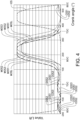
Fig. 4 is a diagram of actuation sequences of exhaust valves shown infig. 3 as functions of the crankshaft angle. -
Fig. 5 is a block diagram depicting steps in a method of controlling the engine infig. 2 . -
Fig. 6 is a block diagram depicting steps in a method of controlling the engine infig. 2 , according to an alternative embodiment of the invention. -
Fig. 7 is a block diagram depicting steps in a method of controlling the engine infig. 2 , according to a further embodiment of the invention. -
Fig. 8 shows an example of an exhaust flow restriction element. -
Fig. 1 shows a vehicle in the form of a truck, or a tractor for a semitrailer. It should be noted that the vehicle can be of a variety of alternative types, e.g. it may be a car, a bus, or a working machine such as a wheel loader. The vehicle comprises a four-strokeinternal combustion engine 1. - As can be seen in
fig. 2 , the engine in this example comprises sixcylinders engine 1 is oriented in the vehicle such that line of cylinders is parallel with the direction of straight travel of the vehicle. It should be noted however that in alternative embodiments the orientation of the engine may have another orientation in the vehicle. For example it may be a transverse engine, i.e. an engine installed such that the crankshaft of the engine is perpendicular to the direction of straight travel of the vehicle. This may be the case e.g. in a bus, where the engine may be a transverse engine mounted in the rear of the bus. The cylinders includefirst cylinders 301 which are the three cylinders located forward in the vehicle direction of forward travel, andsecond cylinders 302 which are the three cylinders located rearward in the vehicle direction of forward travel. - The engine comprises a
turbocharger 4 comprising aturbine 401 in anexhaust conduit arrangement turbocharger 4 also comprises acompressor 402 in anair guide 901 arranged to guide an air flow from thecompressor 402 to thecylinders charge air cooler 902. Theturbine 401 and thecompressor 402 are fixedly connected and rotatable, whereby theturbine 401 is arranged to be driven by gases in theexhaust conduit arrangement compressor 402 which is arranged to compress air in theair guide 901, as in known per se. - The exhaust conduit arrangement comprises a
first exhaust guide 501 arranged to guide a gas flow from thefirst cylinders 301 to theturbine 401, and asecond exhaust guide 502 arranged to guide a gas flow from thesecond cylinders 302 to theturbine 401. Thereby, the flow from thesecond cylinders 302 to theturbine 401 is kept separate from the flow from thefirst cylinders 301 to the turbine. - A
control unit 21 is arranged to determine values of engine parameters affecting the pressure in the cylinders and/or the air mass flow through thecylinders
speed provided from a vehicle speed control function, an actual vehicle speed, and the selected gear ratio of a transmission in the vehicle. The parameters also includes the engine rotational speed, which is determined by means of an engine speed sensor as described below. The engine parameters affecting the pressure in the cylinders and/or the air mass flow further include the pressure in theair guide 901, determined by means of signals from an airguide pressure sensor 211. Also, thecontrol unit 21 is arranged to determine the turbocharger rotational speed by means of a turbochargerrotational speed sensor 215. Further, thecontrol unit 21 is arranged to determine the pressure in the exhaust guides 501, 502 based on signals from an exhaustguide pressure sensor 214 in thefirst exhaust guide 501. Alternatively, an additional exhaust guide pressure sensor may be provided in thesecond exhaust guide 502, or an exhaust guide pressure sensor may be provided in thesecond exhaust guide 502 only. Further, thecontrol unit 21 is arranged to access adata storage unit 213 provided with data correlating values of the engine torque and the engine rotational speed with desired values of the turbocharger rotational speed or the pressure difference across thecylinders - An adjustable air flow restriction element, comprising a
throttle valve 903 in theair guide 901, is arranged to restrict the flow through theair guide 901. The adjustable airflow restriction element 903 is arranged between thecompressor 402 and thecylinders charge air cooler 902 and thecylinders guide pressure sensor 211 is located between the adjustable airflow restriction element 903 and thecylinders flow restriction element 903 may be arranged upstream of thecompressor 402. - The air
flow restriction element 903 is controllable by thecontrol unit 21 via an air flow restriction actuation assembly (not shown) comprising e.g. a stepper motor. In addition, a position sensor (not shown) at the airflow restriction element 903 is connected to thecontrol unit 21, and arranged to register and send to the control unit signals representative of the position of theair restriction element 903, for a position feedback. It should be noted that any alternative type of air flow restriction actuation assembly may be provided; for example such as assembly may include a brushless motor or a pneumatic motor. The airflow restriction element 903 is adapted to provide the air restriction at any level within a non-zero restriction interval depending on the adjustment of the airflow restriction element 903. - A first adjustable exhaust
flow restriction element 601 in the form of a first exhaust throttle valve is arranged in thefirst exhaust guide 501, between thefirst cylinders 301 and theturbine 401. The exhaustguide pressure sensor 214 is located between the first adjustable exhaustflow restriction element 601 and thecylinders 301. A second adjustable exhaustflow restriction element 602 in the form of a second exhaust throttle valve is arranged in thesecond exhaust guide 502, between thesecond cylinders 302 and theturbine 401. The first and second exhaust flow restriction elements are provided as "draw bridge" valves, which may be arranged to not provide any obstacle to the flow when fully open. Eachvalve respective exhaust guide flow restriction elements control unit 21 via a respective exhaust flow restriction actuation assembly (not shown) comprising e.g. a stepper motor. In addition, a position sensor (not shown) at each exhaustflow restriction element control unit 21, and arranged to register and send to the control unit signals representative of the position of the respective exhaustflow restriction element - Each of the first and second exhaust
flow restriction elements control unit 21 of the respective exhaustflow restriction element flow restriction element data storage unit 213 is provided with data correlating values of the engine torque and the engine rotational speed with settings for the first and second exhaustflow restriction elements - It should be noted that in alternative embodiments, a single exhaust guide may be arranged to guide exhaust gases from all cylinders of the engine. In some embodiments, a single exhaust
flow restriction element 601 may be provided downstream of the turbine of the turbocharger. In further embodiments, theturbocharger 4 may be a variable geometry turbocharger, whereby theturbocharger 4 provides, with a flow adjusting function at theturbine 401, the function of the exhaustflow restriction element 601 as described herein. - At each of the
cylinders air guide 901 to therespective cylinder respective cylinder respective exhaust guide - Also, a
fuel system 330 is provided to inject fuel into the cylinders during cycles thereof, and the fuel injection is controllable by thecontrol unit 21. In this example, the fuel system comprises injectors arranged to inject fuel directly into the cylinders. Alternatives are however possible; e.g. the fuel system may have port injection. - The
engine 1 comprises an exhaustvalve actuation assembly 8 comprising a camshaft arrangement comprising arotatable camshaft 801. At eachcylinder 301, 302 acam lobe 803 is fixed to the camshaft for actuation of the exhaust valves. The exhaustvalve actuation assembly 8 also comprises avariator 802 for variable valve timing, more particularly for adjustment of the phase of the camshaft rotation. - Reference is made also to
fig. 3 showing a cross-section through one of thefirst cylinders 301. Eachcylinder piston 303 connected to arotatable crankshaft 101. Thecontrol unit 21 is arranged to determine the engine speed by means of signals from anengine speed sensor 212 at thecrankshaft 101. In alternative embodiments, a sensor may be arranged to detect the speed of thecamshaft 801, whereby the crankshaft speed may be obtained by doubling the sensed camshaft speed.Fig. 3 also shows one of theexhaust valves 7 arranged to control the communication between thefirst cylinder 301 and thefirst exhaust guide 501.Fig. 3 further shows the first adjustable exhaustflow restriction element 601 in thefirst exhaust guide 501. In addition, one of theintake valves 11, arranged to control the communication between thefirst cylinder 301 and theair guide 901, is shown. For actuation of intake valves theengine 1 comprises an intakevalve actuation assembly 12 which may comprise a camshaft arrangement with a rotatable camshaft (not show).Fig. 3 also shows the adjustable airflow restriction element 903 in theair guide 901. - The exhaust
valve actuation assembly 8 comprises for eachcylinder 301, 302 a rocker arm 807 arranged to pivot by contact at one end with therespective cam lobe 803 to actuate theexhaust valves 7. Thecam lobe 803 presents a relatively largemain nose 804, and two relatively small noses, i.e. adecompression nose 805 and acharge nose 806. - When the engine propels the vehicle, a distance is provided between on one hand the rocker arm 807 and on the other hand the
decompression nose 805 and thecharge nose 806. Therefore, thedecompression nose 805 and thecharge nose 806 do not provide any exhaust valve actuation when the engine propels the vehicle. However, during engine braking, the rocker arm 807 is in contact with thedecompression nose 805 and thecharge nose 806, which provide exhaust valve actuation sequences as described below. - The selective engagement of the
decompression nose 805 and thecharge nose 806 is provided by ahydraulic piston 808 at an end of the rocker arm 807 opposite to the end at which the rocker arm 807 is in contact with thecam lobe 803. Thehydraulic piston 808 is controlled by a hydraulic conduit system and a control valve 809 in each rocker arm 807, each control valve 809 being controllable by thecontrol unit 21. - Reference is made also to
fig. 4 showing a diagram of actuation sequences of the exhaust valves shown infig. 3 as functions of the crankshaft angle. At eachcylinder main nose 804 of the thecam lobe 803 is arranged to actuate theexhaust valves 7 so as to perform in each of a plurality of cycles of therespective cylinder exhaust valves 7 in an exhaust stroke of thecylinder decompression nose 805 and thecharge nose 806 of the cam lobe as described above. -
Fig. 4 also shows an intake valve opening sequence IOS performed by the intake valves at the cylinder. - When engine braking is commenced, the rocker arm is brought into contact with the
decompression nose 805 and thecharge nose 806 by control of thehydraulic piston 808 of the rocker arm 807 described above. As a result the lift by the main nose is also increased somewhat so that the main opening sequence appears as indicated by the curve MOS1 infig. 4 . - In addition, the
decompression nose 805 provides a decompression opening sequence DOS1, which is commenced in a compression stroke of thecylinder 301. The decompression opening sequence DOS1 serves to release the air compressed during the compression stroke. Thereby, the decompression opening sequence DOS1 serves to avoid a push-back effect, which the compressed air would otherwise have produced at the end of the compression stroke. - Further during engine braking, the
charge nose 806 provides a charge opening sequence COS1, which is commenced in a second half of an intake stroke of thecylinder 301. Thereby, when thepiston 303 is at its bottom dead centre and the compression stroke is about to start, theexhaust valves 7 open for a short period and the relatively higher pressure in theexhaust guide 501 "charges" the cylinder. As a result of this, the braking 30 effect on thepiston 303 during the compression stroke will be considerably higher than without the charge opening sequence COS1. It should be noted that theexhaust valves 7 are fully closed between the charging opening sequence COS1 and the decompression opening sequence DOS1. In alternative embodiments the degree of opening of theexhaust valves 7 may be merely reduced, without involving a complete closure of the exhaust valves, between the charging opening sequence COS1 and the decompression opening sequence DOS1. - It should be noted that in alternative embodiments the
charge nose 806 and thedecompression nose 805 may be provided on a separate cam lobe adjacent to a cam lobe provided with themain nose 804. Thereby, the rocker arm may be provided in two parts, each following a respective of the cam lobes, although only the part following the cam lobe with the main nose is arranged to actuate the exhaust valves by default. The rocker arm parts may be provided with an engagement mechanism for selectively fixing the rocker arm parts to each other when thecharge nose 806 and thedecompression nose 805 are to provide the corresponding actuation sequences of theexhaust valves 7. In such embodiments, the lift by themain nose 804 may remain unchanged regardless of the engagements of thecharge nose 806 and thedecompression nose 805. - By means of said variator 802 (
fig. 2 ) and the possibility to adjust the phase of the camshaft rotation, the commencement of the exhaust valve actuation sequences MOS1, DOS1, COS1 may be controlled to occur selectively at any crankshaft angle within a non- zero crankshaft angle interval. In fact the entire exhaust valve actuation sequences MOS1, DOS1, COS1 may be moved within the non-zero crankshaft angle interval. Said interval may extend over e.g. 40 crankshaft angle degrees. Other interval sizes are however of course possible. Thedata storage unit 213 is provided with data correlating values of the engine torque and the engine rotational speed with settings for the phase of the camshaft rotation. -
Fig. 4 shows examples of adjusted crankshaft values obtained by the camshaft phase adjustments. By moving the camshaft phase in the direction of rotation of thecamshaft 801, the exhaust valve actuation sequences are moved forward in the cycles as indicated by the curves MOS2, DOS2, COS2 infig. 4 . By moving the camshaft phase opposite to the direction of rotation of thecamshaft 801, the exhaust valve actuation sequences are moved backwards in the cycles as indicated by the curves MOS3, DOS3, COS3 infig. 4 . It should be noted that, apart from the crankshaft angle at which the respective exhaust valve actuation sequence is commenced, the exhaust valve actuation sequences are identical in all cycles. - With reference to
fig. 5 a method of controlling theengine 1 to provide a braking torque will be described. - When the engine braking is commenced, the supply of fuel to the
cylinders - The control valves 809 in the rocker arms 807 at the
cylinders hydraulic pistons 808 to engage the rocker arms 807 with thedecompression noses 805 and thecharge noses 806. Thereby the charging opening sequence COS1 and the decompression opening sequence DOS1 are added S2 to the cycles in the cylinders as described above. - The method also comprises determining S3 the requested engine torque and the engine rotational speed. The
control unit 21 determines by means of the data in the data storage unit 213 a setting for the first and second exhaustflow restriction elements flow restriction elements - The
control unit 21 also determines, based on the requested engine torque and the engine rotational speed, by means of the data in thedata storage unit 213, a setting for the camshaft phase. In an open loop control, thecontrol unit 21 sends signals to thevariator 802 so as to adjust S4 the phase of the camshaft rotation to adjust the crankshaft angles of the exhaust valve actuation sequences MOS1, DOS1, COS1. Retarding the commencement of the exhaust valve actuation sequences MOS1, DOS1, COS1 will reduce the pressure in theair guide 901 which will reduce the braking torque, and vice versa. - Based on the determined requested engine torque and engine rotational speed, the
control unit 21 determines S5 based on the data in the storage unit 213 a desired turbocharger rotational speed value. In a closed loop control, thecontrol unit 21 sends signals to the airflow restriction element 903 in theair guide 901 so as to adjust S6 the airflow restriction element 903, based on the desired turbocharger speed value and feedback signals from theturbocharger speed sensor 215. In the closed loop control, the feedback signals from theturbocharger speed sensor 215 are compared S7 to the desired turbocharger speed value. Moving the airflow restriction element 903 towards a fully closed position will reduce the pressure in theair guide 901 and hence the turbocharger speed, and vice versa. - With reference is made to
fig. 6 , an alternative embodiment of the method will be described. - As in the method described with reference to
fig. 5 , when the engine braking is commenced, the supply of fuel to thecylinders fig. 5 , the method comprises determining S3 the requested engine torque and the engine rotational speed. - The method comprises determining S34 whether the engine speed is above a predetermined threshold value. If the engine speed is below the threshold value, the following steps are performed:
- The
control unit 21 determines by means of the data in the data storage unit 213 a setting for the airflow restriction element 903 in theair guide 901 based on the determined values of the engine torque and the engine rotational speed. The airflow restriction element 903 is adjusted S401 to the determined setting, so as to provide a restriction of the air flow in theair guide 901 correlated with the determined requested engine torque and engine rotational speed. This adjustment is an open loop adjustment, i.e. although it is updated based on changes in the requested engine torque and engine rotational speed, it is not updated with feedback from any parameter from which the air flow through the cylinders or the cylinder pressure may be determined. - The
control unit 21 also determines, based on the requested engine torque and the engine rotational speed, by means of the data in thedata storage unit 213, a setting for the camshaft phase. In an open loop control, thecontrol unit 21 sends signals to thevariator 802 so as to adjust S401 the phase of the camshaft rotation to adjust the crankshaft angles of the exhaust valve actuation sequences MOS1, DOS1, COS1. - Based on the determined requested engine torque and engine rotational speed, the
control unit 21 determines S501, by means of the data in thestorage unit 213, a desired pressure difference across thecylinders control unit 21 sends signals to the exhaustflow restriction elements cylinders guide pressure sensor 211 and the exhaustguide pressure sensor 214. In the closed loop control, the feedback signals are compared S701 to the desired pressure difference across thecylinders flow restriction elements cylinders - The engine speed is continuously or repetitively determined S34. If the engine speed is above the predetermined threshold value, the following steps are performed:
- The
control unit 21 determines, by means of the data in thedata storage unit 213, a setting for the exhaustflow restriction elements flow restriction elements - The
control unit 21 also determines, based on the requested engine torque and the engine rotational speed, a setting for the camshaft phase. In an open loop control, the phase of the camshaft rotation is adjusted S402. - Based on the determined requested engine torque and engine rotational speed, the
control unit 21 determines S502 a desired pressure difference across thecylinders control unit 21 sends signals to the airflow restriction element 903 in theair guide 901 so as to adjust S602 the airflow restriction element 903, based on the desired pressure difference across thecylinders guide pressure sensor 211 and the exhaustguide pressure sensor 214. In the closed loop control, the feedback signals from the airguide pressure sensor 211 and the exhaustguide pressure sensor 214 are compared S702 to the desired pressure difference across thecylinders -
Fig. 7 shows a method of controlling theengine 1 infig. 2 , according to a further embodiment of the invention. The method comprises controlling the engine to provide a braking torque. This control comprises terminating S1 the supply of fuel to thecylinders air guide 901. The control of the engine to provide a braking torque also comprises determining S5 a value of a rotational speed of theturbocharger 4, and adjusting S6, in dependence on the determined turbocharger rotational speed value, the restriction of the flow through theair guide 901, and/or the restriction of the flow through theexhaust guide -
Fig. 8 shows an advantageous example of an exhaustflow restriction element 601. The exhaustflow restriction element 601 is a butterfly valve with aflap 604. An exhaust flowrestriction actuation assembly 603, comprising a stepper motor, a brushless motor or a pneumatic motor, is provided to adjust the exhaustflow restriction element 601, i.e. to adjust the angular position of theflap 604 around anaxle 605. Theflap 604 is non- symmetric, i.e. the extension of the flap is larger on one side of theaxle 605 than on the other side. As a result, the exhaust flow restriction element is arranged to assume, upon a fault in the exhaust flowrestriction actuation assembly 603, a position in which the exhaust flow restriction element does not restrict or block the flow through the exhaust guide. - It is to be understood that the present invention is not limited to the embodiments described above and illustrated in the drawings; rather, the skilled person will recognize that many changes and modifications may be made within the scope of the appended claims.
- Further aspects of the invention are:
- 1. A method of controlling an internal combustion engine (1) in a vehicle comprising a cylinder (301, 302), a fuel system (330) for supplying fuel to the cylinder, an air guide (901) arranged to guide an air flow to the cylinder (301, 302), and an exhaust guide (501, 502) arranged to guide a gas flow from the cylinder (301, 302), the method comprising
- controlling the engine to provide a braking torque, the control comprising,
- terminating (S1) the supply of fuel to the cylinder (301, 302),
- restricting (S4) the flow through the exhaust guide (501, 502), and
- restricting (S6) the flow through the air guide (901),
- characterized in that the control of the engine to provide a braking torque also comprises
- determining (S5) a value of a rotational speed of a turbocharger (4) of the engine, and
- adjusting (S6), in dependence on the determined turbocharger rotational speed value, the restriction of the flow through the air guide (901), and/or the restriction of the flow through the exhaust guide (501, 502).
- 2. A method according to
aspect 1, characterized by adjusting, in dependence on the determined turbocharger rotational speed value, the restriction of the flow through the air guide (901), the adjustment of the restriction of the flow through the air guide (901) being a closed loop adjustment. - 3. A method according to
aspect 2, characterized in that the turbocharger rotational speed is a feedback parameter in the closed loop adjustment. - 4. A method according to aspect 3, characterized in that a desired value of the the turbocharger rotational speed is determined based on one or more of the engine rotational speed, a requested engine braking torque, and a current engine braking torque.
- 5. A method according to any one of the preceding aspects, characterized by adjusting the restriction of the flow through the exhaust guide (501, 502) in dependence on one or more of the engine rotational speed, a requested engine braking torque, and a current engine braking torque.
- 6. A method according to aspect 5, characterized in that the adjustment of the restriction of the flow through the exhaust guide (501, 502) is an open loop adjustment.
- 7. A method according to any one of the preceding aspects, characterized in that restricting the flow through the exhaust guide (501, 502) comprises adjusting an exhaust flow restriction element (601, 602) in the exhaust guide (501, 502), and the exhaust guide (501, 502) is arranged to guide the gas flow from the cylinder (301, 302) to a turbine (401) of the turbocharger, wherein the exhaust flow restriction element (601, 602) is arranged between the cylinder (301, 302) and the turbine (401).
- 8. A method of controlling an internal combustion engine (1) in a vehicle comprising a cylinder (301, 302), a fuel system (330) for supplying fuel to the cylinder, an air guide (901) arranged to guide an air flow to the cylinder (301, 302), and an exhaust guide (501, 502) arranged to guide a gas flow from the cylinder (301, 302), the method comprising
- controlling the engine to provide a braking torque, the control comprising,
- terminating (S1) the supply of fuel to the cylinder (301, 302),
- restricting (S601) the flow through the exhaust guide (501, 502), and
- restricting (S401) the flow through the air guide (901),
- characterized in that the control of the engine to provide a braking torque also comprises
- determining (S501) a value of an engine parameter affecting the pressure in the cylinder and/or the air mass flow through the cylinder, and
- adjusting (S601), in dependence on the determined engine parameter value, the restriction of the flow through the exhaust guide (501, 502), wherein the adjustment of the restriction of the flow through the exhaust guide (501, 502) is a closed loop adjustment, wherein the determined engine parameter is a feedback parameter in the closed loop adjustment.
- 9. A method according to
aspect 8, characterized in that the engine parameter is one of, or a parameter which is dependent on one or more of, a rotational speed of a turbocharger (4) of the engine, a pressure in the exhaust guide (501, 502), and a pressure in the air guide (901). - 10. A method according to any one of aspects 8-9, characterized in that the engine parameter is a difference between a pressure in the air guide (901), and a pressure in the exhaust guide (501, 502).
- 11. A method according to any one of aspects 8-10, characterized in that a desired value of the engine parameter is determined based on one or more of the engine rotational speed, a requested engine braking torque, and a current engine braking torque.
- 12. A method according to any one of aspects 8-11, characterized by adjusting the restriction of the flow through the air guide (901) in dependence on one or more of the engine rotational speed, a requested engine braking torque, and a current engine braking torque.
- 13. A method according to any one of aspects 8-12, characterized in that the adjustment of the restriction of the flow through the air guide (901) is an open loop adjustment.
- 14. A method according to any one of aspects 8-13, characterized by determining (S34) the engine rotational speed, wherein the step of performing a closed loop adjustment of the restriction of the flow through the exhaust guide (501, 502) is omitted if the engine rotational speed is above a threshold value.
- 15. A method according to aspect 14, characterized by, if the engine rotational speed is above the threshold value, determining a value of an engine parameter affecting the pressure in the cylinder and/or the air mass flow through the cylinder, and adjusting, in dependence on the determined engine parameter value, the restriction of the flow through the air guide (901), wherein the adjustment of the restriction of the flow through the air guide (901) is a closed loop adjustment, wherein the determined engine parameter is a feedback parameter in the closed loop adjustment.
- 16. A method according to any one of aspects 14-15, characterized by, if the engine rotational speed is above the threshold value, adjusting the restriction of the flow through the exhaust guide (501, 502) in dependence on one or more of the engine rotational speed, a requested engine braking torque, and a current engine braking torque.
- 17. A method according to any one of aspects 8-16, characterized in that the engine comprises a turbocharger (4) comprising a turbine (401), the exhaust guide (501, 502) being arranged to guide the gas flow from the cylinder (301, 302) to the turbine (401), wherein restricting the flow through the exhaust guide (501, 502) comprises adjusting an exhaust flow restriction element (601, 602) in the exhaust guide (501, 502), and the adjustable exhaust flow restriction element (601, 602) is arranged between the cylinder (301, 302) and the turbine (401).
- 18. A method according to any one of the preceding aspects, characterized in that restricting the flow through the exhaust guide (501, 502) comprises adjusting a throttle valve (601, 602) in the exhaust guide (501, 502), and/or adjusting a flow adjustment function at a turbine (401) of a variable geometry turbocharger (4) of the engine, wherein the exhaust guide (501, 502) is arranged to guide the gas flow from the cylinder to the turbine (401).
- 19. A method according to any one of the preceding aspects, characterized in that adjusting the restriction of the flow through the air guide (901) comprises adjusting a throttle valve (903) in the air guide (901).
- 20. A computer program comprising program code means for performing the steps of any one of aspects 1-19 when said program is run on a computer.
- 21. A computer readable medium carrying a computer program comprising program code means for performing the steps of any one of aspects 1-19 when said program product is run on a computer.
- 22. A control unit (21) configured to perform the steps of the method according to any one of aspects 1-19.
Claims (22)
- A method of controlling an internal combustion engine (1) in a vehicle comprising a cylinder (301, 302), a fuel system (330) for supplying fuel to the cylinder, an air guide (901) arranged to guide an air flow to the cylinder (301, 302), and an exhaust guide (501, 502) arranged to guide a gas flow from the cylinder (301, 302), the method comprising- controlling the engine to provide a braking torque, the control comprising,- terminating (S1) the supply of fuel to the cylinder (301, 302),- restricting (S4) the flow through the exhaust guide (501, 502), and- restricting (S6) the flow through the air guide (901),- characterized in that the control of the engine to provide a braking torque also comprises- determining (S5) a value of a rotational speed of a turbocharger (4) of the engine, and- adjusting (S6), in dependence on the determined turbocharger rotational speed value, the restriction of the flow through the air guide (901), and/or the restriction of the flow through the exhaust guide (501, 502).
- A method according to claim 1, characterized by adjusting, in dependence on the determined turbocharger rotational speed value, the restriction of the flow through the air guide (901), the adjustment of the restriction of the flow through the air guide (901) being a closed loop adjustment.
- A method according to claim 2, characterized in that the turbocharger rotational speed is a feedback parameter in the closed loop adjustment.
- A method according to claim 3, characterized in that a desired value of the the turbocharger rotational speed is determined based on one or more of the engine rotational speed, a requested engine braking torque, and a current engine braking torque.
- A method according to any one of the preceding claims, characterized by adjusting the restriction of the flow through the exhaust guide (501, 502) in dependence on one or more of the engine rotational speed, a requested engine braking torque, and a current engine braking torque.
- A method according to claim 5, characterized in that the adjustment of the restriction of the flow through the exhaust guide (501, 502) is an open loop adjustment.
- A method according to any one of the preceding claims, characterized in that restricting the flow through the exhaust guide (501, 502) comprises adjusting an exhaust flow restriction element (601, 602) in the exhaust guide (501, 502), and the exhaust guide (501, 502) is arranged to guide the gas flow from the cylinder (301, 302) to a turbine (401) of the turbocharger, wherein the exhaust flow restriction element (601, 602) is arranged between the cylinder (301, 302) and the turbine (401).
- A method of controlling an internal combustion engine (1) in a vehicle comprising a cylinder (301, 302), a fuel system (330) for supplying fuel to the cylinder, an air guide (901) arranged to guide an air flow to the cylinder (301, 302), and an exhaust guide (501, 502) arranged to guide a gas flow from the cylinder (301, 302), the method comprising- controlling the engine to provide a braking torque, the control comprising,- terminating (S1) the supply of fuel to the cylinder (301, 302),- restricting (S601) the flow through the exhaust guide (501, 502), and- restricting (S401) the flow through the air guide (901),- characterized in that the control of the engine to provide a braking torque also comprises- determining (S501) a value of an engine parameter affecting the pressure in the cylinder and/or the air mass flow through the cylinder, and- adjusting (S601), in dependence on the determined engine parameter value, the restriction of the flow through the exhaust guide (501, 502), wherein the adjustment of the restriction of the flow through the exhaust guide (501, 502) is a closed loop adjustment, wherein the determined engine parameter is a feedback parameter in the closed loop adjustment.
- A method according to claim 8, characterized in that the engine parameter is one of, or a parameter which is dependent on one or more of, a rotational speed of a turbocharger (4) of the engine, a pressure in the exhaust guide (501, 502), and a pressure in the air guide (901).
- A method according to any one of claims 8-9, characterized in that the engine parameter is a difference between a pressure in the air guide (901), and a pressure in the exhaust guide (501, 502).
- A method according to any one of claims 8-10, characterized in that a desired value of the engine parameter is determined based on one or more of the engine rotational speed, a requested engine braking torque, and a current engine braking torque.
- A method according to any one of claims 8-11, characterized by adjusting the restriction of the flow through the air guide (901) in dependence on one or more of the engine rotational speed, a requested engine braking torque, and a current engine braking torque.
- A method according to any one of claims 8-12, characterized in that the adjustment of the restriction of the flow through the air guide (901) is an open loop adjustment.
- A method according to any one of claims 8-13, characterized by determining (S34) the engine rotational speed, wherein the step of performing a closed loop adjustment of the restriction of the flow through the exhaust guide (501, 502) is omitted if the engine rotational speed is above a threshold value.
- A method according to claim 14, characterized by, if the engine rotational speed is above the threshold value, determining a value of an engine parameter affecting the pressure in the cylinder and/or the air mass flow through the cylinder, and adjusting, in dependence on the determined engine parameter value, the restriction of the flow through the air guide (901), wherein the adjustment of the restriction of the flow through the air guide (901) is a closed loop adjustment, wherein the determined engine parameter is a feedback parameter in the closed loop adjustment.
- A method according to any one of claims 14-15, characterized by, if the engine rotational speed is above the threshold value, adjusting the restriction of the flow through the exhaust guide (501, 502) in dependence on one or more of the engine rotational speed, a requested engine braking torque, and a current engine braking torque.
- A method according to any one of claims 8-16, characterized in that the engine comprises a turbocharger (4) comprising a turbine (401), the exhaust guide (501, 502) being arranged to guide the gas flow from the cylinder (301, 302) to the turbine (401), wherein restricting the flow through the exhaust guide (501, 502) comprises adjusting an exhaust flow restriction element (601, 602) in the exhaust guide (501, 502), and the adjustable exhaust flow restriction element (601, 602) is arranged between the cylinder (301, 302) and the turbine (401).
- A method according to any one of the preceding claims, characterized in that restricting the flow through the exhaust guide (501, 502) comprises adjusting a throttle valve (601, 602) in the exhaust guide (501, 502), and/or adjusting a flow adjustment function at a turbine (401) of a variable geometry turbocharger (4) of the engine, wherein the exhaust guide (501, 502) is arranged to guide the gas flow from the cylinder to the turbine (401).
- A method according to any one of the preceding claims, characterized in that adjusting the restriction of the flow through the air guide (901) comprises adjusting a throttle valve (903) in the air guide (901).
- A computer program comprising program code means for performing the steps of any one of claims 1-19 when said program is run on a computer.
- A computer readable medium carrying a computer program comprising program code means for performing the steps of any one of claims 1-19 when said program product is run on a computer.
- A control unit (21) configured to perform the steps of the method according to any one of claims 1-19.
Applications Claiming Priority (3)
| Application Number | Priority Date | Filing Date | Title |
|---|---|---|---|
| PCT/EP2016/073859 WO2018065053A1 (en) | 2016-10-06 | 2016-10-06 | An internal combustion engine and a method for controlling a braking torque of the engine |
| EP17735097.2A EP3535484B1 (en) | 2016-10-06 | 2017-06-30 | An internal combustion engine and a method for controlling a braking torque of the engine |
| PCT/EP2017/066344 WO2018065131A1 (en) | 2016-10-06 | 2017-06-30 | An internal combustion engine and a method for controlling a braking torque of the engine |
Related Parent Applications (2)
| Application Number | Title | Priority Date | Filing Date |
|---|---|---|---|
| EP17735097.2A Division-Into EP3535484B1 (en) | 2016-10-06 | 2017-06-30 | An internal combustion engine and a method for controlling a braking torque of the engine |
| EP17735097.2A Division EP3535484B1 (en) | 2016-10-06 | 2017-06-30 | An internal combustion engine and a method for controlling a braking torque of the engine |
Publications (1)
| Publication Number | Publication Date |
|---|---|
| EP4212712A1 true EP4212712A1 (en) | 2023-07-19 |
Family
ID=57130363
Family Applications (3)
| Application Number | Title | Priority Date | Filing Date |
|---|---|---|---|
| EP16781087.8A Active EP3523527B2 (en) | 2016-10-06 | 2016-10-06 | Method for controlling a braking torque of the engine |
| EP17735097.2A Active EP3535484B1 (en) | 2016-10-06 | 2017-06-30 | An internal combustion engine and a method for controlling a braking torque of the engine |
| EP23155713.3A Pending EP4212712A1 (en) | 2016-10-06 | 2017-06-30 | An internal combustion engine and a method for controlling a braking torque of the engine |
Family Applications Before (2)
| Application Number | Title | Priority Date | Filing Date |
|---|---|---|---|
| EP16781087.8A Active EP3523527B2 (en) | 2016-10-06 | 2016-10-06 | Method for controlling a braking torque of the engine |
| EP17735097.2A Active EP3535484B1 (en) | 2016-10-06 | 2017-06-30 | An internal combustion engine and a method for controlling a braking torque of the engine |
Country Status (4)
| Country | Link |
|---|---|
| US (2) | US10859007B2 (en) |
| EP (3) | EP3523527B2 (en) |
| CN (2) | CN109804151B (en) |
| WO (2) | WO2018065053A1 (en) |
Families Citing this family (11)
| Publication number | Priority date | Publication date | Assignee | Title |
|---|---|---|---|---|
| US10859007B2 (en) * | 2016-10-06 | 2020-12-08 | Volvo Truck Corporation | Internal combustion engine and a method for controlling a braking torque of the engine |
| CN113330203B (en) | 2018-10-01 | 2024-03-15 | 沃尔沃卡车集团 | Method, computer-readable medium, control unit, internal combustion engine and vehicle for controlling internal combustion engine |
| KR20200063453A (en) * | 2018-11-28 | 2020-06-05 | 현대자동차주식회사 | System and method for controlling exhaust brake of vehicle |
| CN111980792A (en) * | 2019-05-22 | 2020-11-24 | 卡明斯公司 | Exhaust manifold pressure management system on split channel exhaust manifold |
| CN110657036B (en) * | 2019-09-29 | 2022-04-05 | 潍柴动力股份有限公司 | Control method and device of supercharger |
| US11193434B2 (en) * | 2019-11-29 | 2021-12-07 | Caterpillar Inc. | Turbocharger control using an intake throttle valve |
| US11391223B2 (en) | 2020-08-19 | 2022-07-19 | Caterpillar Inc. | Increasing braking power and exhaust gas temperature |
| SE544784C2 (en) * | 2020-10-09 | 2022-11-15 | Scania Cv Ab | Variable Valve Timing Internal Combustion Engine |
| JP2025524675A (en) * | 2022-07-19 | 2025-07-30 | ボルボトラックコーポレーション | Engine System |
| IT202200020052A1 (en) * | 2022-09-29 | 2024-03-29 | Fpt Ind Spa | METHOD AND SYSTEM OF MANAGEMENT OF AN ENGINE BRAKE PROCEDURE IN A DIESEL CYCLE ENGINE |
| EP4663928A1 (en) * | 2024-06-11 | 2025-12-17 | Volvo Truck Corporation | Method for controlling an engine compression braking mode of an engine arrangement |
Citations (10)
| Publication number | Priority date | Publication date | Assignee | Title |
|---|---|---|---|---|
| US5146890A (en) | 1989-02-15 | 1992-09-15 | Ab Volvo | Method and a device for engine braking a four stroke internal combustion engine |
| US20030145591A1 (en) * | 2002-02-05 | 2003-08-07 | Arnold Steven Don | Methods and systems for variable geometry turbocharger control |
| EP1336740A2 (en) * | 2002-02-14 | 2003-08-20 | Holset Engineering Company Limited | Exhaust brake control system |
| WO2008008005A1 (en) * | 2006-07-13 | 2008-01-17 | Volvo Lastvagnar Ab | Method and system for operating a combustion engine brake |
| US20120017869A1 (en) | 2010-07-26 | 2012-01-26 | Man Nutzfahrzeuge Osterreich Ag | Method and device for engine braking |
| US20130074495A1 (en) * | 2011-09-25 | 2013-03-28 | John N. Chi | System for controlling an air handling system including an electric motor-assisted variable geometry turbocharger |
| WO2013159788A1 (en) * | 2012-04-25 | 2013-10-31 | Volvo Lastvagnar Ab | Method and engine brake system to control an engine brake of a vehicle |
| US20140214308A1 (en) * | 2013-01-29 | 2014-07-31 | Cummins Ip, Inc. | Apparatus, system and method for increasing braking power |
| US20160169127A1 (en) | 2014-12-15 | 2016-06-16 | MAN Truck & Bus Österreich AG | Method for controlling an engine braking device and engine braking device |
| WO2017129262A1 (en) * | 2016-01-29 | 2017-08-03 | Volvo Truck Corporation | An internal combustion engine and a method comprising control of the engine to provide a braking torque |
Family Cites Families (59)
| Publication number | Priority date | Publication date | Assignee | Title |
|---|---|---|---|---|
| GB9611015D0 (en) * | 1996-05-25 | 1996-07-31 | Holset Engineering Co | Variable geometry turbocharger control |
| JP3443514B2 (en) * | 1997-03-25 | 2003-09-02 | 株式会社日立ユニシアオートモティブ | Actuator for operating exhaust valve of engine brake device |
| DE19637999A1 (en) | 1996-09-18 | 1998-03-19 | Daimler Benz Ag | Method for operating an engine brake and device for carrying out the method |
| US5787859A (en) | 1997-02-03 | 1998-08-04 | Diesel Engine Retarders, Inc. | Method and apparatus to accomplish exhaust air recirculation during engine braking and/or exhaust gas recirculation during positive power operation of an internal combustion engine |
| JP4261767B2 (en) | 1997-10-03 | 2009-04-30 | ジェイコブス ビークル システムズ、インコーポレイテッド | Method and apparatus for controlling exhaust gas parameters in an internal combustion engine |
| US6647954B2 (en) * | 1997-11-17 | 2003-11-18 | Diesel Engine Retarders, Inc. | Method and system of improving engine braking by variable valve actuation |
| CA2455344A1 (en) * | 2001-04-20 | 2002-10-31 | Jenara Enterprises Ltd. | Apparatus and control for variable exhaust brake |
| US6594996B2 (en) | 2001-05-22 | 2003-07-22 | Diesel Engine Retarders, Inc | Method and system for engine braking in an internal combustion engine with exhaust pressure regulation and turbocharger control |
| EP2325460B1 (en) * | 2002-04-08 | 2012-12-05 | Jacobs Vehicle Systems, Inc. | Compact lost motion system for variable valve actuation |
| US6880572B2 (en) * | 2002-04-15 | 2005-04-19 | Jenara Enterprises Ltd. | Exhaust gas control valve, apparatus and method of controlling exhaust gas flow |
| US6694933B1 (en) * | 2002-09-19 | 2004-02-24 | Diesel Engine Retarders, Inc. | Lost motion system and method for fixed-time valve actuation |
| EP1803913B1 (en) * | 2002-12-23 | 2010-08-11 | Jacobs Vehicle Systems, Inc. | Engine braking methods and apparatus |
| WO2004059131A2 (en) | 2002-12-23 | 2004-07-15 | Jacobs Vehicle Systems, Inc. | Engine braking methods and apparatus |
| US20030178002A1 (en) * | 2003-02-27 | 2003-09-25 | Israel Mark A. | Apparatus and method to operate an engine exhaust brake together with an exhaust gas recirculation system |
| KR101194145B1 (en) * | 2004-03-15 | 2012-10-23 | 자콥스 비히클 시스템즈, 인코포레이티드. | Valve bridge with integrated lost motion system |
| JP2005307898A (en) * | 2004-04-23 | 2005-11-04 | Hino Motors Ltd | Braking force increase mechanism |
| AT500601B1 (en) * | 2004-07-16 | 2006-11-15 | Avl List Gmbh | METHOD FOR OPERATING AN INTERNAL COMBUSTION ENGINE |
| EP1649148B1 (en) | 2004-07-17 | 2006-12-13 | MAHLE Ventiltrieb GmbH | Control device for a valve, particularly a gas exchange valve of an internal combustion engine |
| WO2006023375A2 (en) * | 2004-08-17 | 2006-03-02 | Jacobs Vehicle Systems, Inc. | Combined exhaust restriction and variable valve actuation |
| EP1880095B1 (en) * | 2005-05-13 | 2008-10-08 | Daimler AG | Two-stroke engine braking process for a supercharged internal combustion engine |
| AT502997B1 (en) * | 2005-12-20 | 2013-09-15 | Man Truck & Bus Oesterreich Ag | DEVICE FOR INCREASING THE BRAKING PERFORMANCE OF A MULTI-CYLINDER INTERNAL COMBUSTION ENGINE OF A VEHICLE DURING ENGINE BRAKE OPERATION |
| EP1969207A4 (en) * | 2005-12-28 | 2012-03-07 | Jacobs Vehicle Systems Inc | Method and system for partial cycle bleeder brake |
| US7284533B1 (en) * | 2006-05-08 | 2007-10-23 | Jacobs Vehicle Systems, Inc | Method of operating an engine brake |
| GB2443419A (en) * | 2006-11-06 | 2008-05-07 | Mechadyne Plc | Internal combustion engine valve mechanism allowing variable phase compression braking |
| US8640672B2 (en) * | 2006-12-20 | 2014-02-04 | Volvo Lastvagnar Ab | Engine brake for vehicle |
| DE102007038078A1 (en) | 2007-08-11 | 2009-02-12 | Daimler Ag | Gas exchange valve actuating device |
| US7610897B2 (en) * | 2007-09-07 | 2009-11-03 | Gm Global Technology Operations, Inc. | Valvetrain control systems for internal combustion engines with time and event based control |
| US7565896B1 (en) | 2008-02-28 | 2009-07-28 | Jacobs Vehicle Systems, Inc. | Method for variable valve actuation to provide positive power and engine braking |
| US8109091B2 (en) * | 2008-05-22 | 2012-02-07 | GM Global Technology Operations LLC | Exhaust gas recirculation control systems and methods |
| JP2010001822A (en) | 2008-06-20 | 2010-01-07 | Toyota Motor Corp | Internal combustion engine with turbocharger |
| JP2010024967A (en) * | 2008-07-18 | 2010-02-04 | Toyota Motor Corp | Method and device for controlling drive of vehicle |
| EP2321502B1 (en) * | 2008-07-31 | 2012-03-21 | Pacbrake Company | Self-contained compression brakecontrol module for compression-release brakesystem of internal combustion engine |
| GB0814764D0 (en) * | 2008-08-13 | 2008-09-17 | Cummins Turbo Tech Ltd | Engine braking method and system |
| US8448626B2 (en) * | 2008-08-13 | 2013-05-28 | International Engine Intellectual Property Company, Llc | Exhaust system for engine braking |
| US8065987B2 (en) * | 2009-01-05 | 2011-11-29 | Zhou Yang | Integrated engine brake with mechanical linkage |
| JP4816785B2 (en) | 2009-02-20 | 2011-11-16 | マツダ株式会社 | Control method and control device for engine with turbocharger |
| US8290689B2 (en) * | 2009-04-14 | 2012-10-16 | GM Global Technology Operations LLC | Variable exhaust brake control via turbine vane positioning |
| US7712449B1 (en) * | 2009-05-06 | 2010-05-11 | Jacobs Vehicle Systems, Inc. | Lost motion variable valve actuation system for engine braking and early exhaust opening |
| US8281587B2 (en) * | 2009-08-13 | 2012-10-09 | International Engine Intellectual Property Company, Llc | Supercharged boost-assist engine brake |
| DE102009051261B4 (en) | 2009-10-29 | 2023-05-11 | Daimler Truck AG | Method for operating an engine brake of a motor vehicle |
| US8689770B2 (en) * | 2009-11-02 | 2014-04-08 | International Engine Intellectual Property Company, Llc | High-temperature-flow engine brake with valve actuation |
| DE102011011251A1 (en) * | 2010-02-15 | 2011-08-18 | Magna Steyr Fahrzeugtechnik Ag & Co Kg | Method for increasing the braking effect of a reciprocating internal combustion engine in a motor vehicle |
| WO2011129836A1 (en) * | 2010-04-16 | 2011-10-20 | International Engine Intellectual Property Company, Llc | Engine braking system using spring loaded valve |
| JP6030058B2 (en) | 2010-07-27 | 2016-11-24 | ジェイコブス ビークル システムズ、インコーポレイテッド | Pneumatic valve operating system using both engine brake and positive output engine |
| AT510527B1 (en) | 2010-09-23 | 2012-09-15 | Avl List Gmbh | FOUR-STROKE COMBUSTION ENGINE WITH A MOTOR BRAKE |
| JP2012097604A (en) | 2010-10-29 | 2012-05-24 | Isuzu Motors Ltd | Method and device for controlling exhaust brake of internal combustion engine |
| CN102022154A (en) * | 2011-01-13 | 2011-04-20 | 大连理工大学 | Intake and exhaust valve control method for internal combustion engine |
| AT512332B1 (en) * | 2011-12-23 | 2021-01-15 | MAN TRUCK & BUS OESTERREICH GesmbH | ARRANGEMENT OF A THROTTLE DEVICE FOR CONTROLLING AND / OR REGULATING THE MOTOR BRAKING OPERATION |
| WO2013163054A1 (en) | 2012-04-25 | 2013-10-31 | International Engine Intellectual Property Company, Llc | Engine braking |
| DE102012207085B4 (en) * | 2012-04-27 | 2021-04-29 | Zf Friedrichshafen Ag | Multi-speed transmission |
| US8924131B2 (en) | 2012-05-24 | 2014-12-30 | GM Global Technology Operations LLC | Method and apparatus for controlling a diagnostic module for an exhaust gas sensor |
| ES2537702T3 (en) * | 2012-06-07 | 2015-06-11 | Daf Trucks N.V. | Control of a compression release brake |
| SE539214C2 (en) | 2013-12-05 | 2017-05-16 | Scania Cv Ab | Internal combustion engine, vehicles including such internal combustion engine and method for operating such internal combustion engine |
| US9752464B2 (en) * | 2014-05-28 | 2017-09-05 | Ford Global Technologies, Llc | Supercharged applied ignition internal combustion engine with exhaust-gas turbocharging and method for operating an internal combustion engine of said type |
| CN204783160U (en) * | 2015-07-10 | 2015-11-18 | 浙江师范大学 | Continuously adjustable type engine auxiliary brake device |
| US10393038B2 (en) * | 2016-08-22 | 2019-08-27 | GM Global Technology Operations LLC | Method and apparatus for controlling a two-stage air charging system with mixed EGR |
| US10859007B2 (en) | 2016-10-06 | 2020-12-08 | Volvo Truck Corporation | Internal combustion engine and a method for controlling a braking torque of the engine |
| US10605159B2 (en) * | 2017-09-18 | 2020-03-31 | Ford Global Technologies, Llc | Engine braking for an opposed piston that includes a mechanically driven supercharger |
| US10605158B2 (en) * | 2017-09-18 | 2020-03-31 | Ford Global Technologies, Llc | Engine braking an opposed piston that includes a mechanically driven supercharger |
-
2016
- 2016-10-06 US US16/333,249 patent/US10859007B2/en active Active
- 2016-10-06 WO PCT/EP2016/073859 patent/WO2018065053A1/en not_active Ceased
- 2016-10-06 EP EP16781087.8A patent/EP3523527B2/en active Active
- 2016-10-06 CN CN201680089807.4A patent/CN109804151B/en active Active
-
2017
- 2017-06-30 EP EP17735097.2A patent/EP3535484B1/en active Active
- 2017-06-30 US US16/333,251 patent/US11371444B2/en active Active
- 2017-06-30 CN CN201780061199.0A patent/CN109790780B/en active Active
- 2017-06-30 EP EP23155713.3A patent/EP4212712A1/en active Pending
- 2017-06-30 WO PCT/EP2017/066344 patent/WO2018065131A1/en not_active Ceased
Patent Citations (10)
| Publication number | Priority date | Publication date | Assignee | Title |
|---|---|---|---|---|
| US5146890A (en) | 1989-02-15 | 1992-09-15 | Ab Volvo | Method and a device for engine braking a four stroke internal combustion engine |
| US20030145591A1 (en) * | 2002-02-05 | 2003-08-07 | Arnold Steven Don | Methods and systems for variable geometry turbocharger control |
| EP1336740A2 (en) * | 2002-02-14 | 2003-08-20 | Holset Engineering Company Limited | Exhaust brake control system |
| WO2008008005A1 (en) * | 2006-07-13 | 2008-01-17 | Volvo Lastvagnar Ab | Method and system for operating a combustion engine brake |
| US20120017869A1 (en) | 2010-07-26 | 2012-01-26 | Man Nutzfahrzeuge Osterreich Ag | Method and device for engine braking |
| US20130074495A1 (en) * | 2011-09-25 | 2013-03-28 | John N. Chi | System for controlling an air handling system including an electric motor-assisted variable geometry turbocharger |
| WO2013159788A1 (en) * | 2012-04-25 | 2013-10-31 | Volvo Lastvagnar Ab | Method and engine brake system to control an engine brake of a vehicle |
| US20140214308A1 (en) * | 2013-01-29 | 2014-07-31 | Cummins Ip, Inc. | Apparatus, system and method for increasing braking power |
| US20160169127A1 (en) | 2014-12-15 | 2016-06-16 | MAN Truck & Bus Österreich AG | Method for controlling an engine braking device and engine braking device |
| WO2017129262A1 (en) * | 2016-01-29 | 2017-08-03 | Volvo Truck Corporation | An internal combustion engine and a method comprising control of the engine to provide a braking torque |
Also Published As
| Publication number | Publication date |
|---|---|
| WO2018065053A1 (en) | 2018-04-12 |
| CN109790780A (en) | 2019-05-21 |
| EP3535484B1 (en) | 2023-06-07 |
| US11371444B2 (en) | 2022-06-28 |
| CN109804151B (en) | 2022-03-29 |
| EP3535484A1 (en) | 2019-09-11 |
| CN109790780B (en) | 2022-04-26 |
| EP3523527B1 (en) | 2020-11-04 |
| EP3523527B2 (en) | 2023-11-29 |
| EP3523527A1 (en) | 2019-08-14 |
| CN109804151A (en) | 2019-05-24 |
| WO2018065131A1 (en) | 2018-04-12 |
| US20200200103A1 (en) | 2020-06-25 |
| US10859007B2 (en) | 2020-12-08 |
| US20190249606A1 (en) | 2019-08-15 |
| EP3535484C0 (en) | 2023-06-07 |
Similar Documents
| Publication | Publication Date | Title |
|---|---|---|
| EP3535484B1 (en) | An internal combustion engine and a method for controlling a braking torque of the engine | |
| US10801419B2 (en) | Internal combustion engine and a method comprising control of the engine to provide a braking torque | |
| EP2963263B1 (en) | Control device for internal combustion engine | |
| US8448616B2 (en) | Internal combustion engine cycle | |
| JP6394624B2 (en) | Turbocharged engine | |
| CN111878185B (en) | Control method of variable valve lift mechanism | |
| JP6046918B2 (en) | Valve timing control device | |
| JP2019120204A (en) | Engine control device | |
| US20150300217A1 (en) | Internal combustion engine and control method for internal combustion engine | |
| US12378923B1 (en) | Exhaust vane braking transition and correction strategy | |
| JP6191311B2 (en) | Engine control device | |
| CN116134219B (en) | Boost pressure control method and boost pressure control device for internal combustion engine | |
| US11111842B2 (en) | Method for charge pressure control of an internal combustion engine | |
| JP2019027290A (en) | Engine control device | |
| EP2894319B1 (en) | Method for controlling an internal combustion engine turbocharged by means of a turbocharger during a release step | |
| JP2014105577A (en) | Control device of internal combustion engine | |
| JPH09250352A (en) | Supercharged engine controller | |
| JP2013072372A (en) | Control device of internal combustion engine |
Legal Events
| Date | Code | Title | Description |
|---|---|---|---|
| PUAI | Public reference made under article 153(3) epc to a published international application that has entered the european phase |
Free format text: ORIGINAL CODE: 0009012 |
|
| STAA | Information on the status of an ep patent application or granted ep patent |
Free format text: STATUS: THE APPLICATION HAS BEEN PUBLISHED |
|
| AC | Divisional application: reference to earlier application |
Ref document number: 3535484 Country of ref document: EP Kind code of ref document: P |
|
| AK | Designated contracting states |
Kind code of ref document: A1 Designated state(s): AL AT BE BG CH CY CZ DE DK EE ES FI FR GB GR HR HU IE IS IT LI LT LU LV MC MK MT NL NO PL PT RO RS SE SI SK SM TR |
|
| STAA | Information on the status of an ep patent application or granted ep patent |
Free format text: STATUS: REQUEST FOR EXAMINATION WAS MADE |
|
| 17P | Request for examination filed |
Effective date: 20240119 |
|
| RBV | Designated contracting states (corrected) |
Designated state(s): AL AT BE BG CH CY CZ DE DK EE ES FI FR GB GR HR HU IE IS IT LI LT LU LV MC MK MT NL NO PL PT RO RS SE SI SK SM TR |
|
| STAA | Information on the status of an ep patent application or granted ep patent |
Free format text: STATUS: EXAMINATION IS IN PROGRESS |
|
| 17Q | First examination report despatched |
Effective date: 20241126 |
|
| GRAP | Despatch of communication of intention to grant a patent |
Free format text: ORIGINAL CODE: EPIDOSNIGR1 |
|
| STAA | Information on the status of an ep patent application or granted ep patent |
Free format text: STATUS: GRANT OF PATENT IS INTENDED |
|
| INTG | Intention to grant announced |
Effective date: 20260326 |