EP4212602A1 - Method for disposal of tyres - Google Patents
Method for disposal of tyres Download PDFInfo
- Publication number
- EP4212602A1 EP4212602A1 EP23150889.6A EP23150889A EP4212602A1 EP 4212602 A1 EP4212602 A1 EP 4212602A1 EP 23150889 A EP23150889 A EP 23150889A EP 4212602 A1 EP4212602 A1 EP 4212602A1
- Authority
- EP
- European Patent Office
- Prior art keywords
- reactor
- pyrolysis
- hydrorefining
- flow
- pipe
- Prior art date
- Legal status (The legal status is an assumption and is not a legal conclusion. Google has not performed a legal analysis and makes no representation as to the accuracy of the status listed.)
- Granted
Links
Images


Classifications
-
- C—CHEMISTRY; METALLURGY
- C10—PETROLEUM, GAS OR COKE INDUSTRIES; TECHNICAL GASES CONTAINING CARBON MONOXIDE; FUELS; LUBRICANTS; PEAT
- C10B—DESTRUCTIVE DISTILLATION OF CARBONACEOUS MATERIALS FOR PRODUCTION OF GAS, COKE, TAR, OR SIMILAR MATERIALS
- C10B53/00—Destructive distillation, specially adapted for particular solid raw materials or solid raw materials in special form
- C10B53/07—Destructive distillation, specially adapted for particular solid raw materials or solid raw materials in special form of solid raw materials consisting of synthetic polymeric materials, e.g. tyres
-
- C—CHEMISTRY; METALLURGY
- C10—PETROLEUM, GAS OR COKE INDUSTRIES; TECHNICAL GASES CONTAINING CARBON MONOXIDE; FUELS; LUBRICANTS; PEAT
- C10G—CRACKING HYDROCARBON OILS; PRODUCTION OF LIQUID HYDROCARBON MIXTURES, e.g. BY DESTRUCTIVE HYDROGENATION, OLIGOMERISATION, POLYMERISATION; RECOVERY OF HYDROCARBON OILS FROM OIL-SHALE, OIL-SAND, OR GASES; REFINING MIXTURES MAINLY CONSISTING OF HYDROCARBONS; REFORMING OF NAPHTHA; MINERAL WAXES
- C10G1/00—Production of liquid hydrocarbon mixtures from oil-shale, oil-sand, or non-melting solid carbonaceous or similar materials, e.g. wood, coal
- C10G1/002—Production of liquid hydrocarbon mixtures from oil-shale, oil-sand, or non-melting solid carbonaceous or similar materials, e.g. wood, coal in combination with oil conversion- or refining processes
-
- C—CHEMISTRY; METALLURGY
- C10—PETROLEUM, GAS OR COKE INDUSTRIES; TECHNICAL GASES CONTAINING CARBON MONOXIDE; FUELS; LUBRICANTS; PEAT
- C10G—CRACKING HYDROCARBON OILS; PRODUCTION OF LIQUID HYDROCARBON MIXTURES, e.g. BY DESTRUCTIVE HYDROGENATION, OLIGOMERISATION, POLYMERISATION; RECOVERY OF HYDROCARBON OILS FROM OIL-SHALE, OIL-SAND, OR GASES; REFINING MIXTURES MAINLY CONSISTING OF HYDROCARBONS; REFORMING OF NAPHTHA; MINERAL WAXES
- C10G1/00—Production of liquid hydrocarbon mixtures from oil-shale, oil-sand, or non-melting solid carbonaceous or similar materials, e.g. wood, coal
- C10G1/10—Production of liquid hydrocarbon mixtures from oil-shale, oil-sand, or non-melting solid carbonaceous or similar materials, e.g. wood, coal from rubber or rubber waste
-
- C—CHEMISTRY; METALLURGY
- C10—PETROLEUM, GAS OR COKE INDUSTRIES; TECHNICAL GASES CONTAINING CARBON MONOXIDE; FUELS; LUBRICANTS; PEAT
- C10G—CRACKING HYDROCARBON OILS; PRODUCTION OF LIQUID HYDROCARBON MIXTURES, e.g. BY DESTRUCTIVE HYDROGENATION, OLIGOMERISATION, POLYMERISATION; RECOVERY OF HYDROCARBON OILS FROM OIL-SHALE, OIL-SAND, OR GASES; REFINING MIXTURES MAINLY CONSISTING OF HYDROCARBONS; REFORMING OF NAPHTHA; MINERAL WAXES
- C10G45/00—Refining of hydrocarbon oils using hydrogen or hydrogen-generating compounds
- C10G45/02—Refining of hydrocarbon oils using hydrogen or hydrogen-generating compounds to eliminate hetero atoms without changing the skeleton of the hydrocarbon involved and without cracking into lower boiling hydrocarbons; Hydrofinishing
-
- C—CHEMISTRY; METALLURGY
- C10—PETROLEUM, GAS OR COKE INDUSTRIES; TECHNICAL GASES CONTAINING CARBON MONOXIDE; FUELS; LUBRICANTS; PEAT
- C10G—CRACKING HYDROCARBON OILS; PRODUCTION OF LIQUID HYDROCARBON MIXTURES, e.g. BY DESTRUCTIVE HYDROGENATION, OLIGOMERISATION, POLYMERISATION; RECOVERY OF HYDROCARBON OILS FROM OIL-SHALE, OIL-SAND, OR GASES; REFINING MIXTURES MAINLY CONSISTING OF HYDROCARBONS; REFORMING OF NAPHTHA; MINERAL WAXES
- C10G65/00—Treatment of hydrocarbon oils by two or more hydrotreatment processes only
- C10G65/14—Treatment of hydrocarbon oils by two or more hydrotreatment processes only plural parallel stages only
-
- C—CHEMISTRY; METALLURGY
- C08—ORGANIC MACROMOLECULAR COMPOUNDS; THEIR PREPARATION OR CHEMICAL WORKING-UP; COMPOSITIONS BASED THEREON
- C08J—WORKING-UP; GENERAL PROCESSES OF COMPOUNDING; AFTER-TREATMENT NOT COVERED BY SUBCLASSES C08B, C08C, C08F, C08G or C08H
- C08J11/00—Recovery or working-up of waste materials
- C08J11/04—Recovery or working-up of waste materials of polymers
- C08J11/10—Recovery or working-up of waste materials of polymers by chemically breaking down the molecular chains of polymers or breaking of crosslinks, e.g. devulcanisation
- C08J11/12—Recovery or working-up of waste materials of polymers by chemically breaking down the molecular chains of polymers or breaking of crosslinks, e.g. devulcanisation by dry-heat treatment only
-
- C—CHEMISTRY; METALLURGY
- C08—ORGANIC MACROMOLECULAR COMPOUNDS; THEIR PREPARATION OR CHEMICAL WORKING-UP; COMPOSITIONS BASED THEREON
- C08J—WORKING-UP; GENERAL PROCESSES OF COMPOUNDING; AFTER-TREATMENT NOT COVERED BY SUBCLASSES C08B, C08C, C08F, C08G or C08H
- C08J2319/00—Characterised by the use of rubbers not provided for in groups C08J2307/00 - C08J2317/00
Definitions
- the present invention relates to a process for the disposal of tyres, in particular of end-of-life tyres (ELT), able to give value to this kind of waste.
- ELT end-of-life tyres
- waste burning instead, was considered as a new energy source, so that so-called waste to energy plants were created, incinerators built in such a way to give a combustion as complete as possible, so to limit the production of toxic smokes as much as possible, and to use the heat produced either for domestic district heating in urban centres or as energy for the production of power, reducing then the consumption of other energy sources.
- landfills are considerably decreasing their activity and limiting it to wastes difficult to recycle, such as certain special wastes.
- end-of-use tyres One of the most difficult wastes to dispose of is represented by end-of-use tyres, the waste containing them being commonly called ELT, an abbreviation for end-of-life tyres.
- Combustion of ELT is one of the most classical examples of polluting combustion: more than 100 organic products were isolated from this combustion.
- organic products were isolated from this combustion.
- light hydrocarbons monoaromatic compounds, polycyclic aromatic hydrocarbons, partially oxygenated organic compounds, dioxins, and others; among the others, tyres contain an average of about 1.5% of sulphur (due to their curing) and 0.4% of nitrogen, therefore the formation of sulphur oxides and nitrogen oxides, among the pollutants most desirably avoidable occurs.
- Bolder Industries has developed an electrically heated, screw pyrolysis reactor, dealing mainly with carbon black recovery, so much so to develop more than 2000 different recipes for this.
- Enrestec has developed an indirectly gas heated, two screw stage, pyrolysis reactor, placed the one above the other, with a higher temperature in the higher reactor, where the pyrolysis reaction begins. Carbon black that is compliant with the European environmental standards is obtained.
- New Energy has developed half-batch reactors, working alternating loading and unloading.
- Reoil uses a classic reactor.
- Pyrum uses a vertical reactor, 20 m high, with excellent pressure and temperature control.
- WO 2016/112 371 discloses a process and a system for pyrolysis of rubber derived from tyres, to form fuel such as, for example, naphtha, kerosene, diesel n° 2 and fuel oil, as well as carbon black, powdered active carbon, sulphur and uncondensable gases.
- US 5 949 964 discloses a process for the processing of plastic material wastes to recover raw materials for chemistry and fuel through depolymerisation operations, transforming wastes into a volatile phase and a pumpable one.
- the volatile phase is separated into a gaseous phase and a condensed or condensable part.
- the condensed or condensable part is finished by usual operations. Once the volatile part is separated, the remaining pumpable part is subjected to hydrogenation in a liquid phase, gasification, low temperature carbonisation or a combination of said processes.
- the problem the invention is based on is to provide a process for the disposal of end-of-life tyres (ELT), which overcomes said drawbacks, and allows a complete reuse without environmental problems of the obtained material.
- ELT end-of-life tyres
- This object is reached through a process for the disposal of end-of-life tyres (ELT), including a pyrolysis step of the tyres themselves, wherein pyrolysis oil is obtained, characterised in that the pyrolysis oil is subjected, in a subsequent processing step, to a hydrorefining step.
- Subclaims disclose preferable characteristics of the invention.
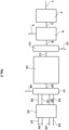
- end-of-life tyres are fed to the process in 1; such feeding is represented in the drawing as a pipe, but given the nature of said feeding, it is more likely a hopper, a screw or any other transport device for random solid materials.
- Feeding 1 enters units 2 for pre-treatment, from which, in pipe 3, a material in the most suitable shape for subsequent operations is output.
- Pipe 3 feeds a pyrolysis reactor 4, from which three flows exit.
- Flow 5 carries powdered carbon black, as a marketable by-product.
- Flow 6 feeds a hydrorefining reactor 7 and flow 8 feeds a regeneration plant for waste oils. From reactor 7 some flows exit (three in the figure) 9, 10 and 11 with the end product.
- Pipe 8 feeds a flash distillation column 12, from which two flows exit: one flow 13 with an aqueous phase and one 14 that is fed to a centrifugal separator 15.
- One flow 16 leaving the centrifugal separator 15 feeds a column for fractional distillation 17, from which flows 18 of bitumen (other marketable by-product), 19, 20, 21 and 22 are output, which are fed to a unit 23 for hydrorefining, from which the flows of products 24, 25, 26 and 27 are output.
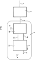
- end-of-life tyres are fed to a pre-treatment unit 2, from which the material to be treated is output in a suitable form for subsequent processing, through pipe 3.
- Pipe 3 in turn, feeds a pyrolysis reactor 4, from which one product flow (powdered carbon black) 5 and one flow 6 feeding a hydrorefining reactor 7 are output. From reactor 7, flows 9, 10 and 11 of end product are output.
- end-of-life tyres are fed through 1 to pre-treatment unit 2, from which the material to be treated is output, through pipe 3, in a suitable shape for subsequent processing.
- Pipe 3 then feeds a pyrolysis reactor 4, from which one flow 5 with powdered carbon black, as a process by-product according to the present invention, and one flow 8 exit, feeding a flash distillation tower 12. From this, one flow of aqueous waste 13 and one flow 14 feeding a centrifugal separator, are output.
- the material to be treated exits through pipe 16 and feeds a fractional distillation tower 17. From this, in 18 the bitumen is output as a by-product, and from flows 19, 20, 21 and 22 the material to be further refined is output, which is fed into reactor 23 for hydrorefining, from which flows 24, 25, 26 and 27 with useful product are output.
- reactor 4 placed in a plant configuration as in any one of previous figures, is divided into two parts. End-of-life tyres are fed through 1 to unit 2 for a pre-treatment, from which material to be treated is output, through the pipe 3, in a suitable shape for subsequent processing.
- Section 4 includes two reactors: a first reactor 28, fed by pipe 3. From this reactor 28 pipe 5, from which carbon black is output, as a by-product for subsequent sale, and two pipes 29, 30 feeding a second reactor 31, exit.
- reactor 28 is a rotating oven, of the type typically used for pyrolysis
- reactor 31 is a plug flow reactor; of course, the opposite configuration is also possible, with the plug flow reactor 28 and the rotating oven 31. From reactor 31 flows 6, 8 and 32 are output.
- the operations depicted in fig. 4 refer to a process like the one in fig.
- pre-treatment unit 2 is a grinder, that reduces tyres into powder or anyway into small-sized pieces, so to make pyrolysis easier through the increase of surface area.
- pre-treatment unit 2 is a grinder, that reduces tyres into powder or anyway into small-sized pieces, so to make pyrolysis easier through the increase of surface area.
- the powder enters reactor 4, it undergoes pyrolysis, at high temperature, higher than 300°C, in the absence of air, so to prevent combustion phenomena.
- High temperature triggers cracking reactions of the polymers that make up tyres, so that mainly aliphatic long chain hydrocarbons are formed, of the fractions suitable for preparing lubricant oils or fuels, such as diesel oil.
- one part of the polymers is dehydrogenated, then giving origin to carbon black.
- pyrolysis oil output from the pyrolysis reactor 4 is split into one flow 6 feeding a hydrorefining reactor 7 and a flow 8 feeding a regeneration plant for waste oils including a final hydrorefining step.
- Said regeneration plant for waste oils includes a fractional distillation step, the tail of which is comprised of bitumen and the heads of which are subjected to a hydrorefining step.
- Flow 6 goes directly to feed a hydrorefining reactor 7 where such refining takes place in conditions that are normal for the production of fuel and lubricants.
- Pipe 14 carries the material to be further treated to a centrifugal separator 15, where the removal of heavier impurities takes place, impurities that later can be further treated with processes such as those developed by Itelyum Regeneration in IT102020000001357 , to obtain quality bitumens, for more valuable uses.
- the product to be treated exits pipe 16 and is fed to column 17 for fractional distillation, which separates different fractions in 19, 20, 21 and 22, while the bitumen, that represents the distillation tail, is discharged in 18.
- Fractions 19, 20, 21, 22 are fed into a reactor 23, where hydrorefining occurs and bases for lubricant exit through pipes 24, 25, 26, 27. Generally, these bases have a higher naphthene than paraffins content.
- a process like that described in fig. 1 requires a quite large installation, but it has the advantage of pushing far the purification of product fractions, increasing their enhancement, also optimising consumption, since a part of the material, already of a quality suitable to be placed on the market, is directly hydrorefined in reactor 7.
- a process like this leads to a not-very-clean product, although it implies lower installation and working costs. It is advantageous, in the case products with a very high value added are not desired.
- the process according to fig. 3 also involves an installation that is simpler than that of fig. 1 .
- the pyrolysis oil output from the pyrolysis reactor 4 feeds a regeneration plant for waste oils including a final hydrorefining step. So, after the pyrolysis step and the discharge of carbon black in 5, the pyrolysis oil is sent, through a single flow 8, to flash distillation column 12, where water is separated out from vent 13 and oil exits through pipe 14, to feed centrifugal separator 15.
- the material to be treated is output through pipe 16 and feeds fractional distillation column 17, from which bitumen as a tail, from discharge pipe 18, and products in flows 19, 20, 21, 22 exit, which undergo a hydrorefining treatment in reactor 23, from which fuels (normally of the diesel oil blend) and bases for lubricants in flows 24, 25, 26, 27 are output.
- these bases have a higher naphthene than paraffins content.
- rotating oven 28 allows a traditional pyrolysis reaction, producing carbon black, which is discharged in 5 and a gas that exits through pipe 29 and a pyrolysis oil, that exits through pipe 30.
- Plug flow reactor 31 receives both gas and pyrolysis oil and performs a second operation that can be considered pyrolysis or cracking, working at a temperature between 350 and 600°C.
- Integration of a plug flow reactor allows to obtain, in addition to pyrolysis oil to be fed to the hydrorefining unit and/or to the regeneration plant for waste oils, also gaseous hydrogen that can be directly used for the hydrorefining step, with a clear saving of material, or it can be sent for sale as a valuable product or one part for one purpose and the other part for the other.
- Hydrogen production has never been obtained in any tyre pyrolysis plants and it is made possible by the sequential combination of rotating oven and plug flow reactor. Particularly advantageous results are obtained if the rotating oven is integrated upstream of the plug flow reactor, but hydrogen can be obtained in both ways.
- a key point of the process is the hydrorefining of pyrolysis oil, a single treatment that completely and effectively removes particulate from the pyrolysis oil of tyres, making the recovery of these materials, today difficult to dispose of, completely recyclable in materials that can be used for other industrial purposes.
- the present invention allows to compensate the present consumption of petroleum products, enhancing wastes that in Italy today are still widely exported, additionally eliminating almost all the exhausts to be disposed of in the disposal of end-of-life tyres.
Landscapes
- Chemical & Material Sciences (AREA)
- Oil, Petroleum & Natural Gas (AREA)
- Engineering & Computer Science (AREA)
- Organic Chemistry (AREA)
- Chemical Kinetics & Catalysis (AREA)
- General Chemical & Material Sciences (AREA)
- Life Sciences & Earth Sciences (AREA)
- Wood Science & Technology (AREA)
- Materials Engineering (AREA)
- Production Of Liquid Hydrocarbon Mixture For Refining Petroleum (AREA)
- Processing And Handling Of Plastics And Other Materials For Molding In General (AREA)
- Processing Of Solid Wastes (AREA)
Abstract
Description
- The present invention relates to a process for the disposal of tyres, in particular of end-of-life tyres (ELT), able to give value to this kind of waste.
- Civilisation resulting from several industrial revolutions has led to an enormous mass of products, to a situation of widespread well-being simply unconceivable before, and to a higher distribution of prosperity on earth. Unfortunately, though, there are some downsides, first of all the huge production of waste, at all levels. Hence, problems relating to pollution -of air, water, and soil- have increased, along with those of contamination, mainly of water streams, and fields.
- Production, which could be defined as frantic, has led to huge masses of waste to dispose of, which not always occurs in an environmentally respectful and, ultimately, healthy manner for everybody.
- While in the past wastes were mainly burnt or abandoned, at first it was attempted to enclose them in so-called landfills, so to keep them all together in a single place, leaving then clean all areas outside the landfill. However, it was soon clear that this way of disposing of wastes still exhibits very serious disadvantages. In particular, in case of confinement of materials without separating them, being often of very different nature the one from the other, it occurred to have to deal with the formation of liquids coming from the reaction between various wastes, and sometimes weathering agents (typically rain and humidity). So, the so-called leachates are generated, which often end up penetrating in groundwater layers, in spite of the waterproofing works usually practiced in these contexts, creating great, and sometimes even very serious, pollution problems of the same. A remedy to this was waterproofing the bottom of the landfills with suitable layers, but this has contributed substantially to soil consumption, without -as mentioned above- achieving a complete solution of the problem.
- It is also to bear in mind that waste burning and their confinement in landfills have the disadvantage that wastes are no longer available for possible additional uses and the result is having materials that are immobilised, in fact, wasted.
- Concerning waste burning, in a first time it was practiced with any kind of waste and was carried out without particular precautions. In this way, though, the combustion was not always complete and could produce toxic smokes, reason why incinerators were considered by the population as something more and more harmful, therefore it became difficult to start new ones, due to the protests of the inhabitants of the areas chosen for the settlement of the same.
- The higher environmental awareness that had been spreading through many sectors of the population worldwide, mainly in the first industrialised countries, mostly affected by the problem, modified the attitude towards wastes, which are considered increasingly less only as such, and increasingly more as a source of new uses.
- Therefore, separate collection of wastes was started and pushed to very high levels, so that most of the wastes could be used as a source of new raw materials, such as paper, plastic, glass, metals. Waste burning, instead, was considered as a new energy source, so that so-called waste to energy plants were created, incinerators built in such a way to give a combustion as complete as possible, so to limit the production of toxic smokes as much as possible, and to use the heat produced either for domestic district heating in urban centres or as energy for the production of power, reducing then the consumption of other energy sources.
- In this way, landfills are considerably decreasing their activity and limiting it to wastes difficult to recycle, such as certain special wastes.
- Concerning waste to energy plants, one should keep in mind that, unfortunately, the energy produced is almost always lower than the energy that was necessary to obtain them, reason why the energy balance remains negative anyway, even though it allows a certain recovery and thus being the balance loss less negative than it was in the past.
- Within the scope of reuse, the so-called circular economy is developing, which allows to use wastes as new raw materials, sometimes also with energy balances close to balance. This seems the future way of disposal, as soon as waste collection is properly organised, as today is not always at the top of the possible efficiency.
- One of the most difficult wastes to dispose of is represented by end-of-use tyres, the waste containing them being commonly called ELT, an abbreviation for end-of-life tyres.
- Combustion of ELT is one of the most classical examples of polluting combustion: more than 100 organic products were isolated from this combustion. Among these there are light hydrocarbons, monoaromatic compounds, polycyclic aromatic hydrocarbons, partially oxygenated organic compounds, dioxins, and others; among the others, tyres contain an average of about 1.5% of sulphur (due to their curing) and 0.4% of nitrogen, therefore the formation of sulphur oxides and nitrogen oxides, among the pollutants most desirably avoidable occurs. Thus, although in principle it is a quite efficient source of thermal energy (a calculation results in that burning 1 kg of tyres yields the same energy of 0,7 kg of aliphatic hydrocarbons), burning of tyres in an incinerator is not desired because of the high number of pollutants that would be produced, and also considering that some attempts of burning in cement plants have led to damage and consequent protests of the inhabitants of the areas surrounding the plants.
- On the other hand, although there are many problems in connection with private mobility, this field is still very important and the increasingly stricter requirements of road safety, impose quite frequent tyre changes, reason why this type of waste is always present in abundant amounts, involving remarkable problems of disposal and dictating then an increase of the costs connected to their employment.
- Processes of pyrolysis and de-curing, were recently started for tyre disposal and recycling.
- Different processes have been developed for pyrolysis, with alternating fortune.
- Bolder Industries has developed an electrically heated, screw pyrolysis reactor, dealing mainly with carbon black recovery, so much so to develop more than 2000 different recipes for this.
- Enrestec has developed an indirectly gas heated, two screw stage, pyrolysis reactor, placed the one above the other, with a higher temperature in the higher reactor, where the pyrolysis reaction begins. Carbon black that is compliant with the European environmental standards is obtained.
- New Energy has developed half-batch reactors, working alternating loading and unloading.
- Reoil uses a classic reactor.
- Pyrum uses a vertical reactor, 20 m high, with excellent pressure and temperature control.
-
WO 2016/112 371 discloses a process and a system for pyrolysis of rubber derived from tyres, to form fuel such as, for example, naphtha, kerosene, diesel n° 2 and fuel oil, as well as carbon black, powdered active carbon, sulphur and uncondensable gases. -
US 5 949 964 discloses a process for the processing of plastic material wastes to recover raw materials for chemistry and fuel through depolymerisation operations, transforming wastes into a volatile phase and a pumpable one. The volatile phase is separated into a gaseous phase and a condensed or condensable part. The condensed or condensable part is finished by usual operations. Once the volatile part is separated, the remaining pumpable part is subjected to hydrogenation in a liquid phase, gasification, low temperature carbonisation or a combination of said processes. - In all cases, though, often the pyrolysis oil obtained from these processes cannot be used as such in possible, subsequent industrial processing, since it still contains otherwise polluting substances, among which rubber fines, and a process allowing to completely dispose of tyres would be desirable, obtaining, in addition to carbon black, another perfectly reusable product, without creating additional wastes.
- Nowadays, there is a growing need of possible processes for improving the quality of pyrolysis oil, making its characteristics aligned, in a way to obtain a high value-added product, suitable for substituting fossil fuels currently used in some important industrial processes. The present invention belongs with full rights in this scope.
- The problem the invention is based on is to provide a process for the disposal of end-of-life tyres (ELT), which overcomes said drawbacks, and allows a complete reuse without environmental problems of the obtained material. This object is reached through a process for the disposal of end-of-life tyres (ELT), including a pyrolysis step of the tyres themselves, wherein pyrolysis oil is obtained, characterised in that the pyrolysis oil is subjected, in a subsequent processing step, to a hydrorefining step. Subclaims disclose preferable characteristics of the invention.
- Further features and advantages of the invention are anyway better apparent from the following detailed description of a preferred embodiment, given only by exemplary and not limiting way and illustrated in the attached drawings, wherein:
-
fig. 1 that is a scheme of the process depicting the phases of the process according to an embodiment of the present invention; -
fig. 2 is a scheme, analogous to that offig. 1 , of an alternative embodiment of the present invention; -
fig. 3 is a scheme, analogous to the preceding two ones, of a second alternative embodiment of the present invention; -
fig. 4 is a scheme, analogous to the preceding ones, depicting only a part of the plant according to the present invention, representing a preferred embodiment. - Based on the embodiment depicted in
fig. 1 , end-of-life tyres are fed to the process in 1; such feeding is represented in the drawing as a pipe, but given the nature of said feeding, it is more likely a hopper, a screw or any other transport device for random solid materials.Feeding 1 entersunits 2 for pre-treatment, from which, inpipe 3, a material in the most suitable shape for subsequent operations is output.Pipe 3 feeds apyrolysis reactor 4, from which three flows exit. Flow 5 carries powdered carbon black, as a marketable by-product.Flow 6 feeds ahydrorefining reactor 7 and flow 8 feeds a regeneration plant for waste oils. Fromreactor 7 some flows exit (three in the figure) 9, 10 and 11 with the end product. -
Pipe 8 feeds aflash distillation column 12, from which two flows exit: oneflow 13 with an aqueous phase and one 14 that is fed to acentrifugal separator 15. Oneflow 16 leaving thecentrifugal separator 15 feeds a column forfractional distillation 17, from which flows 18 of bitumen (other marketable by-product), 19, 20, 21 and 22 are output, which are fed to aunit 23 for hydrorefining, from which the flows ofproducts - Based on the embodiment depicted in
fig. 2 , in 1 end-of-life tyres are fed to apre-treatment unit 2, from which the material to be treated is output in a suitable form for subsequent processing, throughpipe 3.Pipe 3, in turn, feeds apyrolysis reactor 4, from which one product flow (powdered carbon black) 5 and oneflow 6 feeding ahydrorefining reactor 7 are output. Fromreactor 7, flows 9, 10 and 11 of end product are output. - Examining the alternative embodiment of
fig. 3 , end-of-life tyres are fed through 1 to pre-treatmentunit 2, from which the material to be treated is output, throughpipe 3, in a suitable shape for subsequent processing. - Pipe 3 then feeds a
pyrolysis reactor 4, from which one flow 5 with powdered carbon black, as a process by-product according to the present invention, and oneflow 8 exit, feeding aflash distillation tower 12. From this, one flow ofaqueous waste 13 and oneflow 14 feeding a centrifugal separator, are output. The material to be treated exits throughpipe 16 and feeds afractional distillation tower 17. From this, in 18 the bitumen is output as a by-product, and fromflows reactor 23 for hydrorefining, from which flows 24, 25, 26 and 27 with useful product are output. - Examining
fig. 4 ,reactor 4, placed in a plant configuration as in any one of previous figures, is divided into two parts. End-of-life tyres are fed through 1 tounit 2 for a pre-treatment, from which material to be treated is output, through thepipe 3, in a suitable shape for subsequent processing. - Said
pipe 3 feeds thepyrolysis section 4 of the process.Section 4 includes two reactors: afirst reactor 28, fed bypipe 3. From thisreactor 28pipe 5, from which carbon black is output, as a by-product for subsequent sale, and twopipes second reactor 31, exit. Preferably,reactor 28 is a rotating oven, of the type typically used for pyrolysis, whilereactor 31 is a plug flow reactor; of course, the opposite configuration is also possible, with theplug flow reactor 28 and the rotatingoven 31. Fromreactor 31flows fig. 4 refer to a process like the one infig. 1 , there will be bothflow 6 andflow 8 andflow 32; if they refer to a process like the one infig. 2 ,reactor 31 outputs only flow 6 andflow 32; and if they refer to a process like the one infig. 3 ,reactor 31 outputs only flow 8 andflow 32. - Examining what happens in the process, we start dealing with the embodiment of
fig. 1 . - Normally,
pre-treatment unit 2 is a grinder, that reduces tyres into powder or anyway into small-sized pieces, so to make pyrolysis easier through the increase of surface area. When the powder entersreactor 4, it undergoes pyrolysis, at high temperature, higher than 300°C, in the absence of air, so to prevent combustion phenomena. High temperature triggers cracking reactions of the polymers that make up tyres, so that mainly aliphatic long chain hydrocarbons are formed, of the fractions suitable for preparing lubricant oils or fuels, such as diesel oil. On the other side, one part of the polymers is dehydrogenated, then giving origin to carbon black. As it was observed, carbon black is discharged from reactor in 5 as a valuable secondary product, while pyrolysis oil is carried on to the following phases, split into two flows. Essentially, pyrolysis oil output from thepyrolysis reactor 4 is split into oneflow 6 feeding ahydrorefining reactor 7 and aflow 8 feeding a regeneration plant for waste oils including a final hydrorefining step. Said regeneration plant for waste oils includes a fractional distillation step, the tail of which is comprised of bitumen and the heads of which are subjected to a hydrorefining step.Flow 6 goes directly to feed ahydrorefining reactor 7 where such refining takes place in conditions that are normal for the production of fuel and lubricants. The other part, where most of the impurities derived from pyrolysis concentrate, impurities that until today, in fact, have made the pyrolysis process of ELT less interesting that one could suppose, is output from the reactor inflow 8 and feeds aflash distillation column 12, where it is subjected to distillation, at a temperature slightly higher than the boiling point of water, for example 140°C, and this results in removal of water, that leaves throughvent 13. One reason for splitting the pyrolysis oil into twoflows flow 6 and the others inflow 8.Pipe 14 carries the material to be further treated to acentrifugal separator 15, where the removal of heavier impurities takes place, impurities that later can be further treated with processes such as those developed by Itelyum Regeneration inIT102020000001357 exits pipe 16 and is fed tocolumn 17 for fractional distillation, which separates different fractions in 19, 20, 21 and 22, while the bitumen, that represents the distillation tail, is discharged in 18. -
Fractions reactor 23, where hydrorefining occurs and bases for lubricant exit throughpipes - According to a variation of this process, it is possible to feed
flows reactor 23, dedicated to them, directly toreactor 7, where alsopipe 6 merges, so mixing the end products, in case these were economically more advantageous. - A process like that described in
fig. 1 requires a quite large installation, but it has the advantage of pushing far the purification of product fractions, increasing their enhancement, also optimising consumption, since a part of the material, already of a quality suitable to be placed on the market, is directly hydrorefined inreactor 7. - The process according to
fig. 2 is simplified in comparison with that offig. 1 . In practice, after the pyrolysis step inreactor 4, only oneflow 6, containing pyrolysis oil, is sent to thehydrorefining reactor 7 and flows of fuels and bases forlubricants - A process like this leads to a not-very-clean product, although it implies lower installation and working costs. It is advantageous, in the case products with a very high value added are not desired.
- The process according to
fig. 3 also involves an installation that is simpler than that offig. 1 . Essentially, the pyrolysis oil output from thepyrolysis reactor 4 feeds a regeneration plant for waste oils including a final hydrorefining step. So, after the pyrolysis step and the discharge of carbon black in 5, the pyrolysis oil is sent, through asingle flow 8, to flashdistillation column 12, where water is separated out fromvent 13 and oil exits throughpipe 14, to feedcentrifugal separator 15. From thecentrifugal separator 15, the material to be treated is output throughpipe 16 and feedsfractional distillation column 17, from which bitumen as a tail, fromdischarge pipe 18, and products inflows reactor 23, from which fuels (normally of the diesel oil blend) and bases for lubricants inflows fig. 1 , since it requires that all the oil undergoes the whole regeneration process of waste oils. - Concerning embodiments according to
fig. 4 , rotatingoven 28 allows a traditional pyrolysis reaction, producing carbon black, which is discharged in 5 and a gas that exits throughpipe 29 and a pyrolysis oil, that exits throughpipe 30.Plug flow reactor 31 receives both gas and pyrolysis oil and performs a second operation that can be considered pyrolysis or cracking, working at a temperature between 350 and 600°C. Integration of a plug flow reactor allows to obtain, in addition to pyrolysis oil to be fed to the hydrorefining unit and/or to the regeneration plant for waste oils, also gaseous hydrogen that can be directly used for the hydrorefining step, with a clear saving of material, or it can be sent for sale as a valuable product or one part for one purpose and the other part for the other. Hydrogen production has never been obtained in any tyre pyrolysis plants and it is made possible by the sequential combination of rotating oven and plug flow reactor. Particularly advantageous results are obtained if the rotating oven is integrated upstream of the plug flow reactor, but hydrogen can be obtained in both ways. - A key point of the process, anyway, is the hydrorefining of pyrolysis oil, a single treatment that completely and effectively removes particulate from the pyrolysis oil of tyres, making the recovery of these materials, today difficult to dispose of, completely recyclable in materials that can be used for other industrial purposes. In this way, the present invention allows to compensate the present consumption of petroleum products, enhancing wastes that in Italy today are still widely exported, additionally eliminating almost all the exhausts to be disposed of in the disposal of end-of-life tyres.
- Anyway, it is understood that the invention should not be considered limited to the particular arrangement described above, which comprises only one exemplary embodiment, but that different variations are possible, all within the experience of a skilled technician, without therefore leaving the scope of protection of the invention itself, as defined by the following claims.
-
- 1
- ELT Feed
- 2
- Pre-treatment unit
- 3
- Pipe
- 4
- Pyrolysis reactor
- 5
- Pipe
- 6
- Pipe
- 7
- Hydrorefining reactor
- 8
- Pipe
- 9
- Pipe
- 10
- Pipe
- 11
- Pipe
- 12
- Flash Distillation column
- 13
- Pipe
- 14
- Pipe
- 15
- Centrifugal separator
- 16
- Pipe
- 17
- Fractional distillation column
- 18
- Pipe
- 19
- Pipe
- 20
- Pipe
- 21
- Pipe
- 22
- Pipe
- 23
- Hydrorefining reactor
- 24
- Pipe
- 25
- Pipe
- 26
- Pipe
- 27
- Pipe
- 28
- Rotating oven
- 29
- Pipe
- 30
- Pipe
- 31
- Plug flow reactor
Claims (7)
- Process for the disposal of end-of-life tyres (ELT), including a pyrolysis step of the tyres themselves, wherein pyrolysis oil is obtained, characterised in that the pyrolysis oil is subjected, in a subsequent processing step, to a hydrorefining step.
- Process as in 1), characterised in that the pyrolysis oil output from the pyrolysis reactor (4) is split into a flow (6) feeding a hydrorefining reactor (7) and a flow (8) feeding a regeneration plant for waste oils including a final hydrorefining step.
- Process as in 2), characterised in that said regeneration plant for waste oils includes a fractional distillation step for separating the bitumen formed from the oil to be subjected to a hydrorefining step, and in that said hydrorefining occurs in the same hydrorefining reactor (7) where flow (6) converges.
- Process as in 1), characterised in that the pyrolysis oil output from the pyrolysis reactor (4) feeds a hydrorefining reactor (7).
- Process as in 1), characterised in that the pyrolysis oil output from the pyrolysis reactor (4) feeds a regeneration plant for waste oils including a final hydrorefining step.
- Process as in any one of the preceding claims, characterised in that the pyrolysis step is carried out in a first step, in a rotating oven, and in a second step, in a plug flow reactor.
- Process as in 6), characterised in that the second pyrolysis step, carried out in the plug flow reactor, is carried out at a temperature between 350 and 600°C.
Applications Claiming Priority (1)
| Application Number | Priority Date | Filing Date | Title |
|---|---|---|---|
| IT102022000000365A IT202200000365A1 (en) | 2022-01-12 | 2022-01-12 | PROCEDURE FOR DISPOSAL OF TIRES |
Publications (3)
| Publication Number | Publication Date |
|---|---|
| EP4212602A1 true EP4212602A1 (en) | 2023-07-19 |
| EP4212602C0 EP4212602C0 (en) | 2026-02-18 |
| EP4212602B1 EP4212602B1 (en) | 2026-02-18 |
Family
ID=80928633
Family Applications (1)
| Application Number | Title | Priority Date | Filing Date |
|---|---|---|---|
| EP23150889.6A Active EP4212602B1 (en) | 2022-01-12 | 2023-01-10 | Method for disposal of tyres |
Country Status (2)
| Country | Link |
|---|---|
| EP (1) | EP4212602B1 (en) |
| IT (1) | IT202200000365A1 (en) |
Citations (6)
| Publication number | Priority date | Publication date | Assignee | Title |
|---|---|---|---|---|
| DE2731810A1 (en) * | 1977-07-14 | 1978-12-21 | Hoell | Use of pyrolysis oil from scrap rubber, esp. tyres - after sepn. into low-and high-boiling fractions, as an additive to bitumen or solvent for plastics or rubber |
| US5849964A (en) * | 1993-04-03 | 1998-12-15 | Veba Oel Aktiengesellschaft | Process for the processing of salvaged or waste plastic materials |
| US5949964A (en) | 1997-06-17 | 1999-09-07 | Hewlett-Packard Company | Method and apparatus for halftoning of images in a printer |
| WO2013119187A2 (en) * | 2012-02-06 | 2013-08-15 | Farkas Laszlo | Method for thermal decomposition of organic material and equipment for implementation of this method |
| WO2016112371A1 (en) | 2015-01-09 | 2016-07-14 | Sr20 Holdings Llc | Process and system for pyrolysis of tires to fuels and other products |
| IT202000001357A1 (en) | 2020-01-24 | 2021-07-24 | Itelyum Regeneration S P A | ENHANCEMENT OF THE BY-PRODUCTS OF A REGENERATION PROCESS OF USED OILS |
-
2022
- 2022-01-12 IT IT102022000000365A patent/IT202200000365A1/en unknown
-
2023
- 2023-01-10 EP EP23150889.6A patent/EP4212602B1/en active Active
Patent Citations (6)
| Publication number | Priority date | Publication date | Assignee | Title |
|---|---|---|---|---|
| DE2731810A1 (en) * | 1977-07-14 | 1978-12-21 | Hoell | Use of pyrolysis oil from scrap rubber, esp. tyres - after sepn. into low-and high-boiling fractions, as an additive to bitumen or solvent for plastics or rubber |
| US5849964A (en) * | 1993-04-03 | 1998-12-15 | Veba Oel Aktiengesellschaft | Process for the processing of salvaged or waste plastic materials |
| US5949964A (en) | 1997-06-17 | 1999-09-07 | Hewlett-Packard Company | Method and apparatus for halftoning of images in a printer |
| WO2013119187A2 (en) * | 2012-02-06 | 2013-08-15 | Farkas Laszlo | Method for thermal decomposition of organic material and equipment for implementation of this method |
| WO2016112371A1 (en) | 2015-01-09 | 2016-07-14 | Sr20 Holdings Llc | Process and system for pyrolysis of tires to fuels and other products |
| IT202000001357A1 (en) | 2020-01-24 | 2021-07-24 | Itelyum Regeneration S P A | ENHANCEMENT OF THE BY-PRODUCTS OF A REGENERATION PROCESS OF USED OILS |
Also Published As
| Publication number | Publication date |
|---|---|
| EP4212602C0 (en) | 2026-02-18 |
| EP4212602B1 (en) | 2026-02-18 |
| IT202200000365A1 (en) | 2023-07-12 |
Similar Documents
| Publication | Publication Date | Title |
|---|---|---|
| Osayi et al. | Biocrude production through pyrolysis of used tyres | |
| US20180355256A1 (en) | Production of hydrocarbon fuels from plastics | |
| Singh et al. | Plasticwaste management and disposal techniques-Indian scenario | |
| Kaminsky | Possibilities and limits of pyrolysis | |
| Zabaniotou et al. | Analysis of good practices, barriers and drivers for ELTs pyrolysis industrial application | |
| CN85109131A (en) | The process for subsequent treatment of carbonaceous wastes and biomass | |
| Al-Salem | Feedstock and optimal operation for plastics to fuel conversion in pyrolysis | |
| US10358603B1 (en) | Method for producing fuel from plastic or rubber waste material | |
| KR100265273B1 (en) | Emulsification Method and Apparatus of Waste Plastic | |
| Cao et al. | Modelling and simulation of waste tire pyrolysis process for recovery of energy and production of valuable chemicals (BTEX) | |
| CN112955525A (en) | Process and apparatus for depolymerizing of plastic materials for the production of hydrocarbons | |
| EP4212602B1 (en) | Method for disposal of tyres | |
| CN103402930B (en) | The integrated approach of bio oil is prepared by the mud from effluent purifying device | |
| KR100759583B1 (en) | Emulsification Method of Waste Plastic and Reactor for the Method | |
| CN1060203C (en) | Method for producing carbon black, liquefied gas and petroleum oil products by using waste rubber | |
| EP4448682A1 (en) | Process for the recovery of a complex of wastes | |
| Fletcher et al. | The role of pyrolysis in the disposal of waste tyres | |
| CN103145305A (en) | Process for preparing synthesis gas or synthetic natural gas or synthetic gasoline by utilizing oil-containing sludge and incinerator thereof | |
| KR100531501B1 (en) | Oil making apparatus of useless resin | |
| WO2006123970A2 (en) | Method for recycling rubber- or rubber and polymer mixture-containing wastes and a plant for carrying out said method (variants) | |
| AU697420B2 (en) | Method for making fuel oil from waste plastic and device therefor | |
| Gabani et al. | Tyre pyrolysis by using nano-catalyst to improve energy efficiency and fuel quality | |
| Lin et al. | Industrial-scale Processes for Transforming Mixed Plastic Wastes to Oil | |
| Muritu | Thermal Pyrolysis of Plastic Waste: The Implications on Sustainability and Energy Security | |
| Jahirul et al. | A Review on the Thermochemical Recycling of Waste Tyres to Oil for Automobile Engine Application. Energies 2021, 14, 3837 |
Legal Events
| Date | Code | Title | Description |
|---|---|---|---|
| PUAI | Public reference made under article 153(3) epc to a published international application that has entered the european phase |
Free format text: ORIGINAL CODE: 0009012 |
|
| STAA | Information on the status of an ep patent application or granted ep patent |
Free format text: STATUS: THE APPLICATION HAS BEEN PUBLISHED |
|
| AK | Designated contracting states |
Kind code of ref document: A1 Designated state(s): AL AT BE BG CH CY CZ DE DK EE ES FI FR GB GR HR HU IE IS IT LI LT LU LV MC ME MK MT NL NO PL PT RO RS SE SI SK SM TR |
|
| STAA | Information on the status of an ep patent application or granted ep patent |
Free format text: STATUS: REQUEST FOR EXAMINATION WAS MADE |
|
| 17P | Request for examination filed |
Effective date: 20230822 |
|
| RBV | Designated contracting states (corrected) |
Designated state(s): AL AT BE BG CH CY CZ DE DK EE ES FI FR GB GR HR HU IE IS IT LI LT LU LV MC ME MK MT NL NO PL PT RO RS SE SI SK SM TR |
|
| STAA | Information on the status of an ep patent application or granted ep patent |
Free format text: STATUS: EXAMINATION IS IN PROGRESS |
|
| 17Q | First examination report despatched |
Effective date: 20240103 |
|
| GRAP | Despatch of communication of intention to grant a patent |
Free format text: ORIGINAL CODE: EPIDOSNIGR1 |
|
| STAA | Information on the status of an ep patent application or granted ep patent |
Free format text: STATUS: GRANT OF PATENT IS INTENDED |
|
| INTG | Intention to grant announced |
Effective date: 20250916 |
|
| GRAS | Grant fee paid |
Free format text: ORIGINAL CODE: EPIDOSNIGR3 |
|
| GRAA | (expected) grant |
Free format text: ORIGINAL CODE: 0009210 |
|
| STAA | Information on the status of an ep patent application or granted ep patent |
Free format text: STATUS: THE PATENT HAS BEEN GRANTED |
|
| AK | Designated contracting states |
Kind code of ref document: B1 Designated state(s): AL AT BE BG CH CY CZ DE DK EE ES FI FR GB GR HR HU IE IS IT LI LT LU LV MC ME MK MT NL NO PL PT RO RS SE SI SK SM TR |
|
| REG | Reference to a national code |
Ref country code: CH Ref legal event code: F10 Free format text: ST27 STATUS EVENT CODE: U-0-0-F10-F00 (AS PROVIDED BY THE NATIONAL OFFICE) Effective date: 20260218 Ref country code: GB Ref legal event code: FG4D |
|
| REG | Reference to a national code |
Ref country code: IE Ref legal event code: FG4D |
|
| REG | Reference to a national code |
Ref country code: DE Ref legal event code: R096 Ref document number: 602023012028 Country of ref document: DE |
|
| U01 | Request for unitary effect filed |
Effective date: 20260312 |
|
| U07 | Unitary effect registered |
Designated state(s): AT BE BG DE DK EE FI FR IT LT LU LV MT NL PT RO SE SI Effective date: 20260318 |