EP4212349B1 - Printing device for printing a web-shaped substrate - Google Patents
Printing device for printing a web-shaped substrate Download PDFInfo
- Publication number
- EP4212349B1 EP4212349B1 EP23150674.2A EP23150674A EP4212349B1 EP 4212349 B1 EP4212349 B1 EP 4212349B1 EP 23150674 A EP23150674 A EP 23150674A EP 4212349 B1 EP4212349 B1 EP 4212349B1
- Authority
- EP
- European Patent Office
- Prior art keywords
- printing
- web
- substrate
- shaped substrate
- unit
- Prior art date
- Legal status (The legal status is an assumption and is not a legal conclusion. Google has not performed a legal analysis and makes no representation as to the accuracy of the status listed.)
- Active
Links
Images
Classifications
-
- B—PERFORMING OPERATIONS; TRANSPORTING
- B41—PRINTING; LINING MACHINES; TYPEWRITERS; STAMPS
- B41J—TYPEWRITERS; SELECTIVE PRINTING MECHANISMS, i.e. MECHANISMS PRINTING OTHERWISE THAN FROM A FORME; CORRECTION OF TYPOGRAPHICAL ERRORS
- B41J15/00—Devices or arrangements of selective printing mechanisms, e.g. ink-jet printers or thermal printers, specially adapted for supporting or handling copy material in continuous form, e.g. webs
- B41J15/005—Forming loops or sags in webs, e.g. for slackening a web or for compensating variations of the amount of conveyed web material (by arranging a "dancing roller" in a sag of the web material)
-
- B—PERFORMING OPERATIONS; TRANSPORTING
- B65—CONVEYING; PACKING; STORING; HANDLING THIN OR FILAMENTARY MATERIAL
- B65H—HANDLING THIN OR FILAMENTARY MATERIAL, e.g. SHEETS, WEBS, CABLES
- B65H20/00—Advancing webs
- B65H20/16—Advancing webs by web-gripping means, e.g. grippers, clips
- B65H20/18—Advancing webs by web-gripping means, e.g. grippers, clips to effect step-by-step advancement of web
-
- B—PERFORMING OPERATIONS; TRANSPORTING
- B41—PRINTING; LINING MACHINES; TYPEWRITERS; STAMPS
- B41J—TYPEWRITERS; SELECTIVE PRINTING MECHANISMS, i.e. MECHANISMS PRINTING OTHERWISE THAN FROM A FORME; CORRECTION OF TYPOGRAPHICAL ERRORS
- B41J11/00—Devices or arrangements of selective printing mechanisms, e.g. ink-jet printers or thermal printers, for supporting or handling copy material in sheet or web form
- B41J11/0085—Using suction for maintaining printing material flat
-
- B—PERFORMING OPERATIONS; TRANSPORTING
- B41—PRINTING; LINING MACHINES; TYPEWRITERS; STAMPS
- B41J—TYPEWRITERS; SELECTIVE PRINTING MECHANISMS, i.e. MECHANISMS PRINTING OTHERWISE THAN FROM A FORME; CORRECTION OF TYPOGRAPHICAL ERRORS
- B41J2203/00—Embodiments of or processes related to the control of the printing process
- B41J2203/01—Inspecting a printed medium or a medium to be printed using a sensing device
-
- B—PERFORMING OPERATIONS; TRANSPORTING
- B65—CONVEYING; PACKING; STORING; HANDLING THIN OR FILAMENTARY MATERIAL
- B65H—HANDLING THIN OR FILAMENTARY MATERIAL, e.g. SHEETS, WEBS, CABLES
- B65H2301/00—Handling processes for sheets or webs
- B65H2301/50—Auxiliary process performed during handling process
- B65H2301/51—Modifying a characteristic of handled material
- B65H2301/517—Drying material
-
- B—PERFORMING OPERATIONS; TRANSPORTING
- B65—CONVEYING; PACKING; STORING; HANDLING THIN OR FILAMENTARY MATERIAL
- B65H—HANDLING THIN OR FILAMENTARY MATERIAL, e.g. SHEETS, WEBS, CABLES
- B65H2406/00—Means using fluid
- B65H2406/30—Suction means
- B65H2406/32—Suction belts
- B65H2406/321—Suction belts integral in feed table
-
- B—PERFORMING OPERATIONS; TRANSPORTING
- B65—CONVEYING; PACKING; STORING; HANDLING THIN OR FILAMENTARY MATERIAL
- B65H—HANDLING THIN OR FILAMENTARY MATERIAL, e.g. SHEETS, WEBS, CABLES
- B65H2801/00—Application field
- B65H2801/03—Image reproduction devices
- B65H2801/12—Single-function printing machines, typically table-top machines
Definitions
- the invention relates to a printing device for printing a web-shaped substrate, in particular for printing the substrate with portrait images for identification, value or security documents.
- Identification, valuables, or security documents typically contain personal imprints, such as a portrait of their owner.
- Production facilities such as those used in the DE 10 2018 119 178 A1
- This production system for manufacturing data cards for security documents from a laminate composite comprises two decoupled processing lines, namely a production line and a personalization line.
- the portrait image is applied, which was previously printed on a substrate, in particular a film.
- a printing device in which the print head is stationary and a movable print table is provided for applying the print image.
- the print table is a suction plate for flattening the substrate to be printed - from roll to roll.
- the JP 2014 028440 A refers to a printing device that provides a continuous process (a web) for printing. It describes in connection with its Figures 1 and 4 a splice unit, which may be provided together with a buffer unit in the printing device.
- a path position changing device is shown. This device is used to change the reference position in the width direction of a long strip-shaped substrate. Furthermore, a processing system having the web position changing device for changing the reference position in the width direction of the long strip-shaped substrate is described, as well as a method for changing the web position.
- the US 2015/158313 A1 describes a printing device which comprises a pretreatment station for pretreating the paper provided on a roll before it is subsequently printed with a UV ink.
- the printing device for printing a web-shaped substrate, in particular for printing the substrate with portrait images for identification, valuables, or security documents, comprises a supply unit for supplying the web-shaped substrate from a roll.
- the printing device further comprises a substrate guide consisting of one or more deflection rollers for guiding the web-shaped substrate to a printing area.
- a splice unit located downstream of the supply unit in the web transport direction, but upstream of the printing area.
- This splice unit connects the layer of the transport web to be printed to a new roll, allowing printing or production to continue without downtime.
- a suitable arrangement of the splice unit within the printing system, particularly by positioning it directly downstream of the supply unit, further saves installation space.
Landscapes
- Advancing Webs (AREA)
- Ink Jet (AREA)
Description
Die Erfindung betrifft eine Druckeinrichtung zum Bedrucken eines bahnförmigen Substrats, insbesondere zum Bedrucken des Substrats mit Portreitbildern für Ausweis-, Wert- oder Sicherheitsdokumente.The invention relates to a printing device for printing a web-shaped substrate, in particular for printing the substrate with portrait images for identification, value or security documents.
Ausweis-, Wert- oder Sicherheitsdokumente umfassen typischerweise personenspezifische Aufdrucke, wie beispielsweise ein Portraitbild ihres Besitzers. Zur Herstellung solcher Ausweis-, Wert- oder Sicherheitsdokumente kommen beispielsweise Produktionsanlagen in Betracht, wie sie in der
In der
In der
Die
In der
Die
Es ist die Aufgabe der vorliegenden Erfindung, eine Druckeinrichtung anzugeben, die gegenüber aus dem Stand der Technik bekannten Druckeinrichtungen kompaktere Abmessungen aufweist.It is the object of the present invention to provide a printing device which has more compact dimensions than printing devices known from the prior art.
Diese Aufgabe wird durch eine Druckeinrichtung mit den Merkmalen des Anspruchs 1 gelöst. Vorteilhafte Ausgestaltungen mit zweckmäßigen Weiterbildungen der Erfindung sind in den abhängigen Ansprüchen angegeben.This object is achieved by a printing device having the features of claim 1. Advantageous embodiments with expedient further developments of the invention are specified in the dependent claims.
Die erfindungsgemäße Druckeinrichtung zum Bedrucken eines bahnförmigen Substrats, insbesondere zum Bedrucken des Substrats mit Portraitbildern für Ausweis-, Wert- oder Sicherheitsdokumente, umfasst dabei eine Bereitstellungseinheit für die Bereitstellung des bahnförmigen Substrats von einer Rolle. Die Druckeinrichtung umfasst ferner eine Substratführung aus einer oder aus mehreren Umlenkrollen, um das bahnförmige Substrat an einen Druckbereich zu führen. Im Druckbereich ist dabei ein verschiebbar gelagerter Drucktisch bzw. verschiebbar verstellbarer Drucktisch mit einer Unterdruckeinheit vorhanden, um das bahnförmige Substrat abschnittsweise mit einem Unterdruck am Drucktisch zu fixieren. Im Druckbereich liegt außerdem ein während des Druckvorgangs stationär gehaltener Druckkopf vor, der eingerichtet ist, ein Druckbild auf das Substrat aufzubringen mittels einer Verschiebung des Drucktisches zusammen mit dem daran fixierten Substrat.The printing device according to the invention for printing a web-shaped substrate, in particular for printing the substrate with portrait images for identification, valuables, or security documents, comprises a supply unit for supplying the web-shaped substrate from a roll. The printing device further comprises a substrate guide consisting of one or more deflection rollers for guiding the web-shaped substrate to a printing area. In the printing area, there is a displaceably mounted printing table or displaceably adjustable printing table with a vacuum unit for fixing the web-shaped substrate to the printing table in sections using a vacuum. In the printing area, there is also a print head that is held stationary during the printing process and is configured to apply a print image to the substrate by means of a displacement of the printing table together with the substrate fixed thereto.
Durch diese Ausgestaltung des stationär gehaltenen Druckkopfes und des lediglich verschiebbaren Drucktisches wird eine Verkürzung der Druckbereichslänge erzielt.This design of the stationary print head and the merely movable print table results in a shortening of the print area length.
Es hat sich als vorteilhaft erwiesen, wenn eine Spliceeinheit vorliegt, welche in einer Bahntransportrichtung der Bereitstellungseinheit nachgelagert, aber dem Druckbereich vorgelagert ist. Mit dieser Spliceeinheit wird die zu bedruckende Schicht der Transportbahn mit einer neuen Rolle verbunden, um ohne Ausfallzeit weiter drucken bzw. produzieren zu können. Durch eine geeignete Anordnung der Spliceeinheit innerhalb der Druckeinrichtung, insbesondere durch die Anordnung unmittelbar der Bereitstellungseinheit nachgelagert, wird zusätzlich Bauraum eingespart.It has proven advantageous to have a splice unit located downstream of the supply unit in the web transport direction, but upstream of the printing area. This splice unit connects the layer of the transport web to be printed to a new roll, allowing printing or production to continue without downtime. A suitable arrangement of the splice unit within the printing system, particularly by positioning it directly downstream of the supply unit, further saves installation space.
Eine Spliceeinheit ist mit anderen Worten eine Einheit, die eingerichtet ist, ein Rollenende einer Substratbahn einer (annähernd leeren) ersten Rolle an einen Rollenanfang einer Substratbahn einer neuen (vollen) Rolle anzufügen.In other words, a splice unit is a unit that is configured to attach a roll end of a substrate web of a (nearly empty) first roll to a roll start of a substrate web of a new (full) roll.
In diesem Zuge ist ebenfalls von Vorteil, wenn eine Puffereinheit zur zeitweisen Zwischenspeicherung des abgewickelten bahnförmigen Substrats vorliegt, welche in einer Bahntransportrichtung der Bereitstellungseinheit nachgelagert, aber dem Druckbereich vorgelagert ist. Auf diese Weise kann also der Pufferspeicher die durch die Verschiebung des Drucktisches ausgeübten Bewegungen der Transportbahn oder des bahnförmigen Substrats ausgeglichen werden und für ausreichend Nachschub an zu bedruckendem Substrat sorgen.In this context, it is also advantageous to have a buffer unit for temporarily storing the unwound web-shaped substrate. This buffer unit is located downstream of the supply unit in the web transport direction but upstream of the printing area. In this way, the buffer storage can compensate for the movements of the transport track or the web-shaped substrate caused by the displacement of the printing table and ensure a sufficient supply of substrate to be printed.
Es ist von Vorteil, wenn die Puffereinheit wenigstens eine verschiebbare Umlenkrolle aufweist, und wenn die Puffereinheit aufgrund ihrer verschiebbaren Umlenkrolle eingerichtet ist, eine während des Druckvorgangs wegen der Bewegung des Drucktisches entstehende Längenänderung des bahnförmigen Substrats auszugleichen. Somit agiert also die verschiebbare Umlenkrolle als eine Art "Tänzer", um entstehende Längenveränderungen auszugleichen. Dies führt dazu, dass durch die verschiebbare Umlenkrolle die Transportbahn straff gehalten bleibt und keine fehlerhaften Druckbilder beim Bedrucken des Substrats entstehen.It is advantageous if the buffer unit has at least one movable deflection roller, and if the buffer unit, thanks to its movable deflection roller, is configured to compensate for any length changes in the web-shaped substrate that occur during the printing process due to the movement of the printing table. Thus, the movable deflection roller acts as a kind of "dancer" to compensate for any resulting length changes. This ensures that the transport path remains taut thanks to the movable deflection roller, preventing faulty print images from occurring when printing on the substrate.
Um ein möglichst gutes Druckbild auch bei der Weiterbehandlung des Substrats zu erzielen, hat es sich als vorteilhaft erwiesen, wenn nach dem Bedrucken des Substrats die auf das Substrat aufgebrachte Tinte getrocknet wird. Hierfür ist es von Vorteil, dass erfindungsgemäß ein Trocknungsofen vorliegt, der in einer Bahntransportrichtung dem Druckbereich nachgelagert ist.In order to achieve the best possible print image during further processing of the substrate, it has proven advantageous if the ink applied to the substrate is dried after printing. For this purpose, it is advantageous that, according to the invention, a drying oven is provided which is arranged in a Web transport direction is downstream of the printing area.
Es hat sich auch als vorteilhaft erwiesen, wenn Ausschuss frühzeitig erkannt werden kann. Aus diesem Grund ist erfindungsgemäß vorgesehen, dass wenigstens eine Prüfeinheit zur Prüfung des bahnförmigen Substrats vorliegt, die in der Bahntransportrichtung dem Druckbereich nachgelagert, aber dem Trocknungsofen vorgelagert ist. Somit kann die Druckeinrichtung besonders kompakt gebildet werden und Ausschuss wird bereits nahe des Druckbereichs erkannt. Dies sorgt zudem im Fehldruckfall dafür, dass im Folgeprozess erheblich weniger Handling Aufwand entsteht, um den benötigten, neu zu bedruckenden Substratstreifen erneut an die richtige Position in der Produktionsanlage zu befördern.It has also proven advantageous if rejects can be detected early. For this reason, the invention provides for at least one inspection unit for inspecting the web-shaped substrate, which is located downstream of the printing area in the web transport direction but upstream of the drying oven. This allows the printing device to be particularly compact, and rejects are detected close to the printing area. In the event of a misprint, this also ensures that significantly less handling effort is required in the subsequent process to transport the required, reprinted substrate strip to the correct position in the production system.
Es ist von Vorteil, wenn der Druckkopf senkrecht bezüglich einer Verstellbewegung des Drucktisches verschiebbar ist, und zwar zwischen einer Wartungsstellung, in der er einer Kappe gegenüberliegt und von dieser verschließbar oder verschlossen ist, und einer Druckstellung, in der er dem Drucktisch und dem daran fixierten bahnförmigen Substrat für das Bedrucken gegenüberliegt. Somit wird also nicht die Bewegung des Druckkopfes für den Bedruckvorgang genutzt, sondern lediglich dazu, um ihn in eine Wartungsstellung zu verbringen, wo die Druckdüsen durch die Kappe verdeckt werden oder auch eine aktive Reinigung erfahren.It is advantageous if the print head can be moved vertically relative to an adjustment movement of the print bed, namely between a maintenance position, in which it faces a cap and can be closed or is closed by it, and a printing position, in which it faces the print bed and the web-like substrate attached to it for printing. Thus, the movement of the print head is not used for the printing process, but merely to move it to a maintenance position, where the print nozzles are covered by the cap or undergo active cleaning.
Um ein möglichst exaktes Druckbild zu erzielen, hat es sich als vorteilhaft erwiesen, wenn dem Druckbereich eine Ausrichteinheit unmittelbar vorgelagert ist, die eingerichtet ist, die Kanten des Substrats bezüglich dem Drucktisch auszurichten.In order to achieve the most precise print image possible, it has proven advantageous to have an alignment unit immediately upstream of the printing area, which is designed to align the edges of the substrate with respect to the printing table.
Die Druckeinrichtung lässt sich besonders kompakt gestalten, wenn sich die Bereitstellungseinheit in einer obersten Etage befindet, die in Fallrichtung oberhalb des Druckbereichs liegt, wenn ferner die Substratführung das bahnförmige Substrat in der obersten Etage zunächst über den Druckbereich hinweg führt, bevor sie das bahnförmige Substrat in Fallrichtung abwärts zu einer mittleren Etage führt, in welcher sich der Druckbereich befindet, und wenn das bedruckte Substrat in einer unteren Etage in Fallrichtung unterhalb des Druckbereichs ausgegeben wird.The printing device can be designed to be particularly compact if the supply unit is located on an uppermost level which is above the printing area in the direction of fall, if the substrate guide first guides the web-shaped substrate on the uppermost level over the printing area before guiding the web-shaped substrate downwards in the direction of fall to a middle level in which the printing area is located, and if the printed substrate is output on a lower level in the direction of fall below the printing area.
Noch kompakter lässt sich die Maschine dann gestalten, wenn das bedruckte Substrat an derjenigen Seite ausgegeben wird, an der sich auch die Bereitstellungseinheit befindet, sodass die Druckeinrichtung also auch an eine Produktionsanlage unmittelbar angeschlossen werden kann; auch ohne das bedruckte Substrat zunächst noch mal auf eine Rolle aufwickeln zu müssen.The machine can be made even more compact if the printed substrate is output on the same side as the supply unit, so that the printing device can also be directly connected to a production line; even without having to first wind the printed substrate onto a roll.
Weitere Merkmale, Eigenschaften und Vorteile der vorliegenden Erfindung werden im Folgenden anhand von Ausführungsvarianten unter Bezugnahme auf die beigefügte Figur näher beschrieben. Alle bisher und im Folgenden beschriebenen Merkmale sind dabei sowohl einzeln als auch in einer beliebigen Kombination miteinander vorteilhaft. Die im Folgenden beschriebenen Ausführungsvarianten stellen lediglich Beispiele dar, welche den Gegenstand der Erfindung jedoch nicht beschränken. Dabei zeigt:
- Figur 1
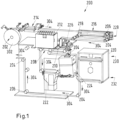
- eine perspektivische und schematische Ansicht einer Druckeinrichtung, die eingerichtet ist, unmittelbar an eine Produktionsanlage zum Herstellen eines Ausweis-, Wert- oder Sicherheitsdokuments angeschlossen zu werden.
- Figure 1
- a perspective and schematic view of a printing device which is designed to be directly connected to a production system for producing an identification, value or security document.
In der
Die Druckeinrichtung 200 umfasst dabei eine Bereitstellungseinheit 202 für die Bereitstellung des bahnförmigen Substrats 300 von einer Rolle 302. Die abgewickelte Rolle 302, insbesondere das bahnförmige Substrat 300, wird mit einer Substratführung 204 mit mehreren Umlenkrollen 206 durch die Druckeinrichtung 200 geführt.The
Der Bereitstellungseinheit 202 ist unmittelbar eine Spliceeinheit 214 nachgeschaltet, um wenigstens eine Schicht des auf der Rolle 302 bereitgestellten Substrats 300 mit dem Substrat 300 der Vorgängerrolle zu verbinden. Die Zuschnitteinheit 214, die Bereitstellungseinheit 202 und eine nachfolgend noch zu erläuternde Puffereinheit 216 sind in einer obersten Etage 228 der Druckeinrichtung 200 angeordnet.A
Die Spliceeinheit 214 ist der Bereitstellungseinheit 202 entlang einer Bahntransportrichtung 304 nachgelagert, jedoch einem noch näher zu erläuternden Druckbereich 208 vorgelagert. Die ebenfalls optionale Puffereinheit 216 dient der zeitweisen Zwischenspeicherung des abgewickelten bahnförmigen Substrats 300. Die Puffereinheit 216, die sich ebenfalls in der Bahntransportrichtung 304 der Bereitstellungseinheit 202 nachgelagert befindet, aber dem Druckbereich 208 vorgelagert ist, ist außerdem auch der Spliceeinheit 214 nachgelagert. Die Puffereinheit 216 umfasst lediglich exemplarisch eine verschiebbare Umlenkrolle 218, wobei die Puffereinheit 216 aufgrund ihrer verschiebbaren Umlenkrolle 218 eingerichtet ist, eine während des Druckvorgangs wegen der Bewegung eines Drucktisches 210 entstehende Längenänderung des bahnförmigen Substrats 300 auszugleichen. Die verschiebbare Umlenkrolle 218 ist senkrecht zur Fallrichtung verstellbar gelagert.The
Ausgehend von der Puffereinheit 216 ist dieser eine ebenfalls optionale Ausrichteinheit 226 nachgelagert. Diese Ausrichteinheit 226 ist dabei unmittelbar dem Druckbereich 208 vorgelagert, und damit eingerichtet, die Kanten des Substrats 200 bezüglich dem Drucktisch 210 auszurichten. Die Substratführung 204 führt dabei also das bahnförmige Substrat an den Drucktisch 210 und damit an den Druckbereich 208.Starting from the
Im Druckbereich 208 liegt dabei der verschiebbar gelagerte bzw. verstellbare Drucktisch 210 vor, der eine Unterdruckeinheit aufweist, um das bahnförmige Substrat 300 abschnittsweise mit einem Unterdruck zu fixieren. Hierfür weist der Drucktisch 210 beispielsweise eine Platte auf, die mit mehreren Sauglöchern versehen ist, um das bahnförmige Substrat 300 an der Platte anzusaugen. Die Verstellung des Drucktisches 210 erfolgt dabei ebenfalls senkrecht bezüglich der Fallrichtung.The
Im Druckbereich 208 liegt außerdem ein während des Druckvorgangs stationär gehaltener Druckkopf 212 vor, der eingerichtet ist, ein Druckbild auf das Substrat 300 aufzubringen, und zwar mittels einer Verschiebung des Drucktisches 210 zusammen mit dem daran fixierten Substrat 300. Somit liegt also mit anderen Worten der Druckkopf 212 oder die mehreren Druckköpfe 212 mit ihren Druckdüsen stationär vor, wobei das Druckbild durch das Verschieben des Drucktisches 210 bezüglich dem Druckkopf 212 entsteht. Um auch hier das bahnförmige Substrat 300 straff zu halten, können optional eine oder mehrere Umlenkrollen oder auch eine oder mehrere verschiebbare Umlenkrollen vorliegen, um die Spannung ihm bahnförmigen Material während des Druckvorgangs aufrechtzuerhalten, wobei insbesondere die verschiebbaren Umlenkrollen nach Art eines "Tänzers" ausgebildet sind, der senkrecht bezüglich der Fallrichtung verstellt wird.In the
Wurde das Substrat 300 im Druckbereich 208 dann mit dem Druckbild bedruckt, so wird das bedruckte Substrat in Transportrichtung 304, vorliegend in Fallrichtung abwärts, weitertransportiert. Auf diese Weise liegt also der Druckbereich 208 in einer mittleren Etage 230 vor, welche sich in Fallrichtung abwärts unterhalb der obersten Etage 228 der Druckeinrichtung 200 befindet.Once the substrate 300 has been printed with the print image in the
In der unteren Etage 232 liegt dabei eine Mehrzahl an ebenfalls optionalen Prüfeinheiten 222, 224 vor, um das bahnförmige Substrat 300, insbesondere optisch, zu prüfen. Mit anderen Worten sind die Prüfeinheiten 222, 224 in der Bahntransportrichtung 304 dem Druckbereich 208 nachgelagert, aber einem Trocknungsofen 220 vorgelagert. Dies führt dazu, dass Ausschuss noch vor dem Trocknen erkannt werden kann und somit ein geringerer Abschnitt des bahnförmigen Substrats 300 auszutauschen ist, sollten Fehler erkannt werden.The
Vorliegend durchläuft das bahnförmige Substrat 300 zunächst die Prüfeinheit 222, die die Unterseite des bahnförmigen Substrats 300 optisch untersucht. Erst anschließend gelangt das bahnförmige Substrat 300 in die Prüfeinheit 224, die dann das Druckbild und die Druckseite überprüft. In Bahntransportrichtung 304 nachgelagert liegt dann der Trocknungsofen 220 vor, um die noch feuchte Tinte vollständig zu trocknen. Anschließend führt die Substratführung 204 das bedruckte Substrat 300 seitlich aus der Druckeinrichtung 200 aus.In this case, the web-shaped substrate 300 first passes through the
Das Ausführen des bedruckten Substrats 300 erfolgt dabei an derjenigen Seite der Druckeinrichtung 200, an der sich auch die Bereitstellungseinheit 202 mit ihrer Rolle 302 des Substrats 300 befindet.The printed substrate 300 is discharged on the side of the
Es ist zu erkennen, dass sich die Bereitstellungseinheit 202 in der obersten Etage 228 befindet, die in Fallrichtung oberhalb des Druckbereichs 208 liegt, wobei die Substratführung 206 das bahnförmige Substrat 300 in der obersten Etage zunächst über den Druckbereich 218 hinwegführt, bevor sie das bahnförmige Substrat 300 in Fallrichtung abwärts zu der mittleren Etage 230 führt, in welcher sich der Druckbereich befindet, wobei das bedruckte Substrat 300 in einer unteren Etage 232 in Fallrichtung unterhalb des Druckbereichs 208 ausgegeben wird.It can be seen that the
Durch diese Ausgestaltung wird eine besonders kompakte Druckeinrichtung 200 gebildet. Insbesondere ist ihre längste Seite verkürzt gegenüber bekannten Druckeinrichtungen 200 dieser Art. Um die Länge der Druckeinrichtung 200 zusätzlich zu begrenzen und damit Bauraum einzusparen, ist vorliegend optional vorgesehen, dass der Druckkopf 212 senkrecht bezüglich der Verstellbewegung des Drucktisches 210 verschiebbar ist zwischen einer Wartungsstellung, in der er einer Kappe (oder einer "Cappingstation") gegenüberliegt oder von dieser verschließbar oder verschlossen ist, und einer Druckstellung, in der er dem Drucktisch 210 und dem daran fixierten bahnförmigen Substrat 300 für das Bedrucken gegenüberliegt.This configuration creates a particularly
Die erfindungsgemäße Druckeinrichtung 200 hat sich zudem deshalb gut bewährt, weil das bedruckte bahnförmige Substrat 300 anschließend nicht mehr auf einer Rolle aufgerollt wird, sodass das bedruckte bahnförmige Substrat 300 unmittelbar an die nachfolgende Produktionsanlage anschließbar ist. Mit der gewählten Gestaltung ist eine besonders kompakte Druckeinrichtung 200 geschaffen.The
- 200200
- DruckeinrichtungPrinting device
- 202202
- BereitstellungseinheitProvisioning unit
- 204204
- SubstratführungSubstrate guidance
- 206206
- Umlenkrollepulley
- 208208
- Druckbereichpressure range
- 210210
- Drucktischprinting table
- 212212
- Druckkopfprint head
- 214214
- Zuschnitteinheit (Splicetisch)Cutting unit (splice table)
- 216216
- PuffereinheitBuffer unit
- 218218
- verstellbare Umlenkrolle (Tänzer)adjustable pulley (dancer)
- 220220
- Trocknungsofendrying oven
- 222222
- Prüfeinheit (Unterseite)Test unit (bottom)
- 224224
- Prüfeinheit (Oberseite)Test unit (top)
- 226226
- AusrichteinheitAlignment unit
- 228228
- oberste Etagetop floor
- 230230
- mittlere Etagemiddle floor
- 232232
- untere Etagelower floor
- 300300
- SubstratSubstrat
- 302302
- Rollerole
Claims (8)
- A printing device (200) for printing on a web-shaped substrate (300), in particular for printing the substrate with portrait images for identity, value or security documents,with a supply unit (202) for supplying the web-shaped substrate (300) from a roll (302),with a substrate guidance (204) consisting of one or more pulleys (206) to guide the web-shaped substrate (300) to a printing area (206),wherein a displaceably mounted printing table (210) with a negative pressure unit is present in the printing area (206) in order to fix the web-shaped substrate (300) in sections with a negative pressure,and wherein a print head (212), which is held stationary during the printing process and is configured to apply a printed image to the substrate (300) by means of a displacement of the printing table (210) together with the substrate (300) fixed thereto, is present in the printing area (208), characterized in that a drying oven (220) is present which is downstream of the printing area (208) in a web transport direction (304), and in that at least one test unit (222, 224) for testing the web-shaped substrate (300) is present, which is downstream of the printing area (208) in the web transport direction (304) but upstream of the drying oven (220).
- The printing device (200) according to claim 1, characterized in that a splice unit (214) is present which is downstream of the supply unit (102) in a web transport direction (304), but upstream of the printing area (208).
- The printing device (200) according to claim 1 or 2, characterized in that there is a buffer unit (216) for temporary intermediate storage of the unwound web-shaped substrate (300), which is downstream of the supply unit (202) in a web transport direction (304), but upstream of the printing area (208).
- The printing device (200) according to claim 3, characterized in that the buffer unit (216) has at least one displaceable pulley (218), and in that the buffer unit (216), by virtue of its displaceable pulley (218), is configured to compensate for a change in length of the web-shaped substrate (300) occurring during the printing process due to the movement of the printing table (210).
- The printing device (200) according to any one of claims 1 to 4, characterized in that the print head (212) is displaceable perpendicularly with respect to the adjustment movement of the printing table (210) between a maintenance position, in which it lies opposite a cap and can be closed or sealed by the latter, and a printing position, in which it lies opposite the printing table (210) and the web-shaped substrate (300) fixed thereto for printing.
- The printing device (200) according to any one of claims 1 to 5, characterized in that an alignment unit (226) is arranged directly upstream of the printing area (208), which is configured to align the edges of the substrate (300) with respect to the printing table (210).
- The printing device (200) according to any one of claims 1 to 6, characterized in that the supply unit (202) is located in a top floor (228), which is located above the printing area (208) in the direction of fall, in that the substrate guidance (206) first guides the web-shaped substrate (300) in the top floor (228) over the printing area (208) before it guides the web-shaped substrate (300) downwards in the falling direction to a middle floor (230), in which the printing area (208) is located, and in that the printed substrate (300) is output in a lower floor in the falling direction below the printing area (208).
- The printing device (200) according to claim 7, characterized in that the substrate (300) is output on the side on which the supply unit (202) is also located.
Applications Claiming Priority (1)
| Application Number | Priority Date | Filing Date | Title |
|---|---|---|---|
| DE102022100765.0A DE102022100765A1 (en) | 2022-01-13 | 2022-01-13 | Printing device for printing a web-shaped substrate |
Publications (2)
| Publication Number | Publication Date |
|---|---|
| EP4212349A1 EP4212349A1 (en) | 2023-07-19 |
| EP4212349B1 true EP4212349B1 (en) | 2025-03-12 |
Family
ID=85036408
Family Applications (1)
| Application Number | Title | Priority Date | Filing Date |
|---|---|---|---|
| EP23150674.2A Active EP4212349B1 (en) | 2022-01-13 | 2023-01-09 | Printing device for printing a web-shaped substrate |
Country Status (2)
| Country | Link |
|---|---|
| EP (1) | EP4212349B1 (en) |
| DE (1) | DE102022100765A1 (en) |
Family Cites Families (8)
| Publication number | Priority date | Publication date | Assignee | Title |
|---|---|---|---|---|
| JP4849673B2 (en) * | 2006-07-06 | 2012-01-11 | 株式会社ミマキエンジニアリング | Printing apparatus, conveying apparatus, and printing method |
| JP2014028440A (en) * | 2012-07-31 | 2014-02-13 | Canon Inc | Printing apparatus and printing method |
| JP6142789B2 (en) * | 2013-12-10 | 2017-06-07 | セイコーエプソン株式会社 | Recording device |
| JP6435212B2 (en) * | 2015-02-27 | 2018-12-05 | 株式会社Screenホールディングス | Web position changing device, processing system, and web position changing method |
| DE102018119178A1 (en) | 2018-08-07 | 2020-02-13 | Bundesdruckerei Gmbh | Production plant for the production of data cards for security documents |
| WO2020162881A1 (en) | 2019-02-05 | 2020-08-13 | Hewlett-Packard Development Company, L.P. | Tension adjustments in printers to prevent slipping |
| DE102019103156A1 (en) | 2019-02-08 | 2020-08-13 | Bundesdruckerei Gmbh | Device and method for printing on a print substrate |
| WO2021126151A1 (en) | 2019-12-16 | 2021-06-24 | Hewlett-Packard Development Company, L.P. | Imaging device having print media spools |
-
2022
- 2022-01-13 DE DE102022100765.0A patent/DE102022100765A1/en active Pending
-
2023
- 2023-01-09 EP EP23150674.2A patent/EP4212349B1/en active Active
Also Published As
| Publication number | Publication date |
|---|---|
| DE102022100765A1 (en) | 2023-07-13 |
| EP4212349A1 (en) | 2023-07-19 |
Similar Documents
| Publication | Publication Date | Title |
|---|---|---|
| DE4401959C2 (en) | Carrier drum roller for a paper machine | |
| DE69128604T2 (en) | Winding method and winding device | |
| EP0792829B1 (en) | Method of winding a paper web into a roll | |
| EP3147116B1 (en) | Corrugated board system | |
| EP0680911A1 (en) | Device for winding up a continously fed web, especially for paper web | |
| DE2935743A1 (en) | ADDITIONAL DEVICE ON ROLLING DEVICES AND METHOD FOR ROLLING UP PRESSURE-SENSITIVE MATERIALS | |
| WO2002022368A1 (en) | Ink jet printing device | |
| WO2009074670A1 (en) | Modular film unit | |
| DE4334029C2 (en) | Carrier roll winding machine | |
| DE102016208079A1 (en) | Method for collision avoidance, adjustment of the distance and actuator stroke | |
| DE3034670C2 (en) | Paper guide for a web-fed rotary printing press | |
| DE19513143C2 (en) | Winding machine for winding a running web, in particular a paper web, into a roll | |
| DE69508350T2 (en) | METHOD AND DEVICE FOR FINISHING THE OUTER LAYERS OF A WRAP FORMED BY WINDING A SHEET | |
| EP1055624B1 (en) | Device for winding a web | |
| AT508281B1 (en) | METHOD IN A UNWIRED DEVICE FOR A FIBERTRY, IN PARTICULAR FOR A PAPER OR CARDBOARD RAW, AND A DEVICE FOR UNWIRED OPERATION FOR A FIBERGLAY, ESPECIALLY FOR A PAPER OR CARDBOARD TRACK | |
| EP4212349B1 (en) | Printing device for printing a web-shaped substrate | |
| DE3035652A1 (en) | PRESSURE ROLLERS IN CARRIER ROLLING MACHINES | |
| DE102007046949A1 (en) | Web offset press and method and apparatus for replacing the printing plate in a web offset press | |
| DE19524905A1 (en) | Coiling machine with support rolls for winding webs of material, especially paper or cardboard - has movably mounted support rollers with gap between under which is air receiver with compressed air inflow and outlet | |
| DE19508846C2 (en) | Device for inserting a leading edge of a printing plate | |
| EP1038815A2 (en) | Winding machine for continuously winding a material web | |
| DE3114406A1 (en) | Printing machine for printing on a web of plastic film | |
| DE4324337A1 (en) | Remoistening device for a printed paper web | |
| EP0379205B1 (en) | Cloth-spreading machine | |
| EP0123049B1 (en) | Printing machine with a pressure cylinder, in particular a screen printer |
Legal Events
| Date | Code | Title | Description |
|---|---|---|---|
| PUAI | Public reference made under article 153(3) epc to a published international application that has entered the european phase |
Free format text: ORIGINAL CODE: 0009012 |
|
| STAA | Information on the status of an ep patent application or granted ep patent |
Free format text: STATUS: THE APPLICATION HAS BEEN PUBLISHED |
|
| AK | Designated contracting states |
Kind code of ref document: A1 Designated state(s): AL AT BE BG CH CY CZ DE DK EE ES FI FR GB GR HR HU IE IS IT LI LT LU LV MC ME MK MT NL NO PL PT RO RS SE SI SK SM TR |
|
| STAA | Information on the status of an ep patent application or granted ep patent |
Free format text: STATUS: REQUEST FOR EXAMINATION WAS MADE |
|
| 17P | Request for examination filed |
Effective date: 20240116 |
|
| RBV | Designated contracting states (corrected) |
Designated state(s): AL AT BE BG CH CY CZ DE DK EE ES FI FR GB GR HR HU IE IS IT LI LT LU LV MC ME MK MT NL NO PL PT RO RS SE SI SK SM TR |
|
| GRAP | Despatch of communication of intention to grant a patent |
Free format text: ORIGINAL CODE: EPIDOSNIGR1 |
|
| STAA | Information on the status of an ep patent application or granted ep patent |
Free format text: STATUS: GRANT OF PATENT IS INTENDED |
|
| RIC1 | Information provided on ipc code assigned before grant |
Ipc: B41J 11/00 20060101ALN20240919BHEP Ipc: B65H 20/18 20060101ALI20240919BHEP Ipc: B65H 19/10 20060101ALI20240919BHEP Ipc: B41J 15/00 20060101ALI20240919BHEP Ipc: B42D 25/40 20140101AFI20240919BHEP |
|
| INTG | Intention to grant announced |
Effective date: 20241009 |
|
| GRAS | Grant fee paid |
Free format text: ORIGINAL CODE: EPIDOSNIGR3 |
|
| GRAA | (expected) grant |
Free format text: ORIGINAL CODE: 0009210 |
|
| STAA | Information on the status of an ep patent application or granted ep patent |
Free format text: STATUS: THE PATENT HAS BEEN GRANTED |
|
| AK | Designated contracting states |
Kind code of ref document: B1 Designated state(s): AL AT BE BG CH CY CZ DE DK EE ES FI FR GB GR HR HU IE IS IT LI LT LU LV MC ME MK MT NL NO PL PT RO RS SE SI SK SM TR |
|
| REG | Reference to a national code |
Ref country code: GB Ref legal event code: FG4D Free format text: NOT ENGLISH |
|
| REG | Reference to a national code |
Ref country code: CH Ref legal event code: EP |
|
| P01 | Opt-out of the competence of the unified patent court (upc) registered |
Free format text: CASE NUMBER: APP_8351/2025 Effective date: 20250219 |
|
| REG | Reference to a national code |
Ref country code: DE Ref legal event code: R096 Ref document number: 502023000659 Country of ref document: DE |
|
| REG | Reference to a national code |
Ref country code: IE Ref legal event code: FG4D Free format text: LANGUAGE OF EP DOCUMENT: GERMAN |
|
| PG25 | Lapsed in a contracting state [announced via postgrant information from national office to epo] |
Ref country code: RS Free format text: LAPSE BECAUSE OF FAILURE TO SUBMIT A TRANSLATION OF THE DESCRIPTION OR TO PAY THE FEE WITHIN THE PRESCRIBED TIME-LIMIT Effective date: 20250612 |
|
| PG25 | Lapsed in a contracting state [announced via postgrant information from national office to epo] |
Ref country code: FI Free format text: LAPSE BECAUSE OF FAILURE TO SUBMIT A TRANSLATION OF THE DESCRIPTION OR TO PAY THE FEE WITHIN THE PRESCRIBED TIME-LIMIT Effective date: 20250312 |
|
| PG25 | Lapsed in a contracting state [announced via postgrant information from national office to epo] |
Ref country code: ES Free format text: LAPSE BECAUSE OF FAILURE TO SUBMIT A TRANSLATION OF THE DESCRIPTION OR TO PAY THE FEE WITHIN THE PRESCRIBED TIME-LIMIT Effective date: 20250312 |
|
| REG | Reference to a national code |
Ref country code: LT Ref legal event code: MG9D |
|
| PG25 | Lapsed in a contracting state [announced via postgrant information from national office to epo] |
Ref country code: NO Free format text: LAPSE BECAUSE OF FAILURE TO SUBMIT A TRANSLATION OF THE DESCRIPTION OR TO PAY THE FEE WITHIN THE PRESCRIBED TIME-LIMIT Effective date: 20250612 |
|
| PG25 | Lapsed in a contracting state [announced via postgrant information from national office to epo] |
Ref country code: HR Free format text: LAPSE BECAUSE OF FAILURE TO SUBMIT A TRANSLATION OF THE DESCRIPTION OR TO PAY THE FEE WITHIN THE PRESCRIBED TIME-LIMIT Effective date: 20250312 |
|
| REG | Reference to a national code |
Ref country code: NL Ref legal event code: MP Effective date: 20250312 |
|
| PG25 | Lapsed in a contracting state [announced via postgrant information from national office to epo] |
Ref country code: LV Free format text: LAPSE BECAUSE OF FAILURE TO SUBMIT A TRANSLATION OF THE DESCRIPTION OR TO PAY THE FEE WITHIN THE PRESCRIBED TIME-LIMIT Effective date: 20250312 |
|
| PG25 | Lapsed in a contracting state [announced via postgrant information from national office to epo] |
Ref country code: BG Free format text: LAPSE BECAUSE OF FAILURE TO SUBMIT A TRANSLATION OF THE DESCRIPTION OR TO PAY THE FEE WITHIN THE PRESCRIBED TIME-LIMIT Effective date: 20250312 Ref country code: GR Free format text: LAPSE BECAUSE OF FAILURE TO SUBMIT A TRANSLATION OF THE DESCRIPTION OR TO PAY THE FEE WITHIN THE PRESCRIBED TIME-LIMIT Effective date: 20250613 |
|
| PG25 | Lapsed in a contracting state [announced via postgrant information from national office to epo] |
Ref country code: NL Free format text: LAPSE BECAUSE OF FAILURE TO SUBMIT A TRANSLATION OF THE DESCRIPTION OR TO PAY THE FEE WITHIN THE PRESCRIBED TIME-LIMIT Effective date: 20250312 |
|
| PG25 | Lapsed in a contracting state [announced via postgrant information from national office to epo] |
Ref country code: SE Free format text: LAPSE BECAUSE OF FAILURE TO SUBMIT A TRANSLATION OF THE DESCRIPTION OR TO PAY THE FEE WITHIN THE PRESCRIBED TIME-LIMIT Effective date: 20250312 |
|
| PG25 | Lapsed in a contracting state [announced via postgrant information from national office to epo] |
Ref country code: SM Free format text: LAPSE BECAUSE OF FAILURE TO SUBMIT A TRANSLATION OF THE DESCRIPTION OR TO PAY THE FEE WITHIN THE PRESCRIBED TIME-LIMIT Effective date: 20250312 |
|
| PG25 | Lapsed in a contracting state [announced via postgrant information from national office to epo] |
Ref country code: PT Free format text: LAPSE BECAUSE OF FAILURE TO SUBMIT A TRANSLATION OF THE DESCRIPTION OR TO PAY THE FEE WITHIN THE PRESCRIBED TIME-LIMIT Effective date: 20250714 |
|
| PG25 | Lapsed in a contracting state [announced via postgrant information from national office to epo] |
Ref country code: IT Free format text: LAPSE BECAUSE OF FAILURE TO SUBMIT A TRANSLATION OF THE DESCRIPTION OR TO PAY THE FEE WITHIN THE PRESCRIBED TIME-LIMIT Effective date: 20250312 Ref country code: PL Free format text: LAPSE BECAUSE OF FAILURE TO SUBMIT A TRANSLATION OF THE DESCRIPTION OR TO PAY THE FEE WITHIN THE PRESCRIBED TIME-LIMIT Effective date: 20250312 |
|
| REG | Reference to a national code |
Ref country code: CH Ref legal event code: W10 Free format text: ST27 STATUS EVENT CODE: U-0-0-W10-W00 (AS PROVIDED BY THE NATIONAL OFFICE) Effective date: 20251015 |
|
| PG25 | Lapsed in a contracting state [announced via postgrant information from national office to epo] |
Ref country code: EE Free format text: LAPSE BECAUSE OF FAILURE TO SUBMIT A TRANSLATION OF THE DESCRIPTION OR TO PAY THE FEE WITHIN THE PRESCRIBED TIME-LIMIT Effective date: 20250312 Ref country code: CZ Free format text: LAPSE BECAUSE OF FAILURE TO SUBMIT A TRANSLATION OF THE DESCRIPTION OR TO PAY THE FEE WITHIN THE PRESCRIBED TIME-LIMIT Effective date: 20250312 |
|
| PG25 | Lapsed in a contracting state [announced via postgrant information from national office to epo] |
Ref country code: RO Free format text: LAPSE BECAUSE OF FAILURE TO SUBMIT A TRANSLATION OF THE DESCRIPTION OR TO PAY THE FEE WITHIN THE PRESCRIBED TIME-LIMIT Effective date: 20250312 |
|
| PG25 | Lapsed in a contracting state [announced via postgrant information from national office to epo] |
Ref country code: SK Free format text: LAPSE BECAUSE OF FAILURE TO SUBMIT A TRANSLATION OF THE DESCRIPTION OR TO PAY THE FEE WITHIN THE PRESCRIBED TIME-LIMIT Effective date: 20250312 |
|
| PG25 | Lapsed in a contracting state [announced via postgrant information from national office to epo] |
Ref country code: IS Free format text: LAPSE BECAUSE OF FAILURE TO SUBMIT A TRANSLATION OF THE DESCRIPTION OR TO PAY THE FEE WITHIN THE PRESCRIBED TIME-LIMIT Effective date: 20250712 |
|
| RAP4 | Party data changed (patent owner data changed or rights of a patent transferred) |
Owner name: BUNDESDRUCKEREI GMBH |
|
| REG | Reference to a national code |
Ref country code: DE Ref legal event code: R097 Ref document number: 502023000659 Country of ref document: DE |
|
| PG25 | Lapsed in a contracting state [announced via postgrant information from national office to epo] |
Ref country code: DK Free format text: LAPSE BECAUSE OF FAILURE TO SUBMIT A TRANSLATION OF THE DESCRIPTION OR TO PAY THE FEE WITHIN THE PRESCRIBED TIME-LIMIT Effective date: 20250312 |
|
| PLBE | No opposition filed within time limit |
Free format text: ORIGINAL CODE: 0009261 |
|
| STAA | Information on the status of an ep patent application or granted ep patent |
Free format text: STATUS: NO OPPOSITION FILED WITHIN TIME LIMIT |
|
| REG | Reference to a national code |
Ref country code: CH Ref legal event code: L10 Free format text: ST27 STATUS EVENT CODE: U-0-0-L10-L00 (AS PROVIDED BY THE NATIONAL OFFICE) Effective date: 20260121 |