EP4212310A1 - Verfahren und vorrichtung zum verbinden von kunststofffolien durch thermisches fügen sowie verwendung einer schlagpresse - Google Patents
Verfahren und vorrichtung zum verbinden von kunststofffolien durch thermisches fügen sowie verwendung einer schlagpresse Download PDFInfo
- Publication number
- EP4212310A1 EP4212310A1 EP22151636.2A EP22151636A EP4212310A1 EP 4212310 A1 EP4212310 A1 EP 4212310A1 EP 22151636 A EP22151636 A EP 22151636A EP 4212310 A1 EP4212310 A1 EP 4212310A1
- Authority
- EP
- European Patent Office
- Prior art keywords
- plastic films
- welding
- sealing
- jaws
- weld seam
- Prior art date
- Legal status (The legal status is an assumption and is not a legal conclusion. Google has not performed a legal analysis and makes no representation as to the accuracy of the status listed.)
- Pending
Links
Images

Classifications
-
- B—PERFORMING OPERATIONS; TRANSPORTING
- B29—WORKING OF PLASTICS; WORKING OF SUBSTANCES IN A PLASTIC STATE IN GENERAL
- B29C—SHAPING OR JOINING OF PLASTICS; SHAPING OF MATERIAL IN A PLASTIC STATE, NOT OTHERWISE PROVIDED FOR; AFTER-TREATMENT OF THE SHAPED PRODUCTS, e.g. REPAIRING
- B29C65/00—Joining or sealing of preformed parts, e.g. welding of plastics materials; Apparatus therefor
- B29C65/02—Joining or sealing of preformed parts, e.g. welding of plastics materials; Apparatus therefor by heating, with or without pressure
- B29C65/38—Impulse heating
-
- B—PERFORMING OPERATIONS; TRANSPORTING
- B29—WORKING OF PLASTICS; WORKING OF SUBSTANCES IN A PLASTIC STATE IN GENERAL
- B29C—SHAPING OR JOINING OF PLASTICS; SHAPING OF MATERIAL IN A PLASTIC STATE, NOT OTHERWISE PROVIDED FOR; AFTER-TREATMENT OF THE SHAPED PRODUCTS, e.g. REPAIRING
- B29C66/00—General aspects of processes or apparatus for joining preformed parts
- B29C66/40—General aspects of joining substantially flat articles, e.g. plates, sheets or web-like materials; Making flat seams in tubular or hollow articles; Joining single elements to substantially flat surfaces
- B29C66/41—Joining substantially flat articles ; Making flat seams in tubular or hollow articles
- B29C66/43—Joining a relatively small portion of the surface of said articles
- B29C66/432—Joining a relatively small portion of the surface of said articles for making tubular articles or closed loops, e.g. by joining several sheets ; for making hollow articles or hollow preforms
-
- B—PERFORMING OPERATIONS; TRANSPORTING
- B29—WORKING OF PLASTICS; WORKING OF SUBSTANCES IN A PLASTIC STATE IN GENERAL
- B29C—SHAPING OR JOINING OF PLASTICS; SHAPING OF MATERIAL IN A PLASTIC STATE, NOT OTHERWISE PROVIDED FOR; AFTER-TREATMENT OF THE SHAPED PRODUCTS, e.g. REPAIRING
- B29C65/00—Joining or sealing of preformed parts, e.g. welding of plastics materials; Apparatus therefor
- B29C65/002—Joining methods not otherwise provided for
-
- B—PERFORMING OPERATIONS; TRANSPORTING
- B29—WORKING OF PLASTICS; WORKING OF SUBSTANCES IN A PLASTIC STATE IN GENERAL
- B29C—SHAPING OR JOINING OF PLASTICS; SHAPING OF MATERIAL IN A PLASTIC STATE, NOT OTHERWISE PROVIDED FOR; AFTER-TREATMENT OF THE SHAPED PRODUCTS, e.g. REPAIRING
- B29C65/00—Joining or sealing of preformed parts, e.g. welding of plastics materials; Apparatus therefor
- B29C65/002—Joining methods not otherwise provided for
- B29C65/004—Cold joining
-
- B—PERFORMING OPERATIONS; TRANSPORTING
- B29—WORKING OF PLASTICS; WORKING OF SUBSTANCES IN A PLASTIC STATE IN GENERAL
- B29C—SHAPING OR JOINING OF PLASTICS; SHAPING OF MATERIAL IN A PLASTIC STATE, NOT OTHERWISE PROVIDED FOR; AFTER-TREATMENT OF THE SHAPED PRODUCTS, e.g. REPAIRING
- B29C65/00—Joining or sealing of preformed parts, e.g. welding of plastics materials; Apparatus therefor
- B29C65/02—Joining or sealing of preformed parts, e.g. welding of plastics materials; Apparatus therefor by heating, with or without pressure
- B29C65/022—Particular heating or welding methods not otherwise provided for
-
- B—PERFORMING OPERATIONS; TRANSPORTING
- B29—WORKING OF PLASTICS; WORKING OF SUBSTANCES IN A PLASTIC STATE IN GENERAL
- B29C—SHAPING OR JOINING OF PLASTICS; SHAPING OF MATERIAL IN A PLASTIC STATE, NOT OTHERWISE PROVIDED FOR; AFTER-TREATMENT OF THE SHAPED PRODUCTS, e.g. REPAIRING
- B29C65/00—Joining or sealing of preformed parts, e.g. welding of plastics materials; Apparatus therefor
- B29C65/74—Joining or sealing of preformed parts, e.g. welding of plastics materials; Apparatus therefor by welding and severing, or by joining and severing, the severing being performed in the area to be joined, next to the area to be joined, in the joint area or next to the joint area
- B29C65/743—Joining or sealing of preformed parts, e.g. welding of plastics materials; Apparatus therefor by welding and severing, or by joining and severing, the severing being performed in the area to be joined, next to the area to be joined, in the joint area or next to the joint area using the same tool for both joining and severing, said tool being monobloc or formed by several parts mounted together and forming a monobloc
-
- B—PERFORMING OPERATIONS; TRANSPORTING
- B29—WORKING OF PLASTICS; WORKING OF SUBSTANCES IN A PLASTIC STATE IN GENERAL
- B29C—SHAPING OR JOINING OF PLASTICS; SHAPING OF MATERIAL IN A PLASTIC STATE, NOT OTHERWISE PROVIDED FOR; AFTER-TREATMENT OF THE SHAPED PRODUCTS, e.g. REPAIRING
- B29C65/00—Joining or sealing of preformed parts, e.g. welding of plastics materials; Apparatus therefor
- B29C65/74—Joining or sealing of preformed parts, e.g. welding of plastics materials; Apparatus therefor by welding and severing, or by joining and severing, the severing being performed in the area to be joined, next to the area to be joined, in the joint area or next to the joint area
- B29C65/743—Joining or sealing of preformed parts, e.g. welding of plastics materials; Apparatus therefor by welding and severing, or by joining and severing, the severing being performed in the area to be joined, next to the area to be joined, in the joint area or next to the joint area using the same tool for both joining and severing, said tool being monobloc or formed by several parts mounted together and forming a monobloc
- B29C65/7437—Joining or sealing of preformed parts, e.g. welding of plastics materials; Apparatus therefor by welding and severing, or by joining and severing, the severing being performed in the area to be joined, next to the area to be joined, in the joint area or next to the joint area using the same tool for both joining and severing, said tool being monobloc or formed by several parts mounted together and forming a monobloc the tool being a perforating tool
-
- B—PERFORMING OPERATIONS; TRANSPORTING
- B29—WORKING OF PLASTICS; WORKING OF SUBSTANCES IN A PLASTIC STATE IN GENERAL
- B29C—SHAPING OR JOINING OF PLASTICS; SHAPING OF MATERIAL IN A PLASTIC STATE, NOT OTHERWISE PROVIDED FOR; AFTER-TREATMENT OF THE SHAPED PRODUCTS, e.g. REPAIRING
- B29C66/00—General aspects of processes or apparatus for joining preformed parts
- B29C66/01—General aspects dealing with the joint area or with the area to be joined
- B29C66/05—Particular design of joint configurations
- B29C66/10—Particular design of joint configurations particular design of the joint cross-sections
- B29C66/11—Joint cross-sections comprising a single joint-segment, i.e. one of the parts to be joined comprising a single joint-segment in the joint cross-section
- B29C66/112—Single lapped joints
- B29C66/1122—Single lap to lap joints, i.e. overlap joints
-
- B—PERFORMING OPERATIONS; TRANSPORTING
- B29—WORKING OF PLASTICS; WORKING OF SUBSTANCES IN A PLASTIC STATE IN GENERAL
- B29C—SHAPING OR JOINING OF PLASTICS; SHAPING OF MATERIAL IN A PLASTIC STATE, NOT OTHERWISE PROVIDED FOR; AFTER-TREATMENT OF THE SHAPED PRODUCTS, e.g. REPAIRING
- B29C66/00—General aspects of processes or apparatus for joining preformed parts
- B29C66/01—General aspects dealing with the joint area or with the area to be joined
- B29C66/05—Particular design of joint configurations
- B29C66/20—Particular design of joint configurations particular design of the joint lines, e.g. of the weld lines
- B29C66/21—Particular design of joint configurations particular design of the joint lines, e.g. of the weld lines said joint lines being formed by a single dot or dash or by several dots or dashes, i.e. spot joining or spot welding
-
- B—PERFORMING OPERATIONS; TRANSPORTING
- B29—WORKING OF PLASTICS; WORKING OF SUBSTANCES IN A PLASTIC STATE IN GENERAL
- B29C—SHAPING OR JOINING OF PLASTICS; SHAPING OF MATERIAL IN A PLASTIC STATE, NOT OTHERWISE PROVIDED FOR; AFTER-TREATMENT OF THE SHAPED PRODUCTS, e.g. REPAIRING
- B29C66/00—General aspects of processes or apparatus for joining preformed parts
- B29C66/40—General aspects of joining substantially flat articles, e.g. plates, sheets or web-like materials; Making flat seams in tubular or hollow articles; Joining single elements to substantially flat surfaces
- B29C66/41—Joining substantially flat articles ; Making flat seams in tubular or hollow articles
- B29C66/43—Joining a relatively small portion of the surface of said articles
-
- B—PERFORMING OPERATIONS; TRANSPORTING
- B29—WORKING OF PLASTICS; WORKING OF SUBSTANCES IN A PLASTIC STATE IN GENERAL
- B29C—SHAPING OR JOINING OF PLASTICS; SHAPING OF MATERIAL IN A PLASTIC STATE, NOT OTHERWISE PROVIDED FOR; AFTER-TREATMENT OF THE SHAPED PRODUCTS, e.g. REPAIRING
- B29C66/00—General aspects of processes or apparatus for joining preformed parts
- B29C66/40—General aspects of joining substantially flat articles, e.g. plates, sheets or web-like materials; Making flat seams in tubular or hollow articles; Joining single elements to substantially flat surfaces
- B29C66/41—Joining substantially flat articles ; Making flat seams in tubular or hollow articles
- B29C66/43—Joining a relatively small portion of the surface of said articles
- B29C66/432—Joining a relatively small portion of the surface of said articles for making tubular articles or closed loops, e.g. by joining several sheets ; for making hollow articles or hollow preforms
- B29C66/4322—Joining a relatively small portion of the surface of said articles for making tubular articles or closed loops, e.g. by joining several sheets ; for making hollow articles or hollow preforms by joining a single sheet to itself
-
- B—PERFORMING OPERATIONS; TRANSPORTING
- B29—WORKING OF PLASTICS; WORKING OF SUBSTANCES IN A PLASTIC STATE IN GENERAL
- B29C—SHAPING OR JOINING OF PLASTICS; SHAPING OF MATERIAL IN A PLASTIC STATE, NOT OTHERWISE PROVIDED FOR; AFTER-TREATMENT OF THE SHAPED PRODUCTS, e.g. REPAIRING
- B29C66/00—General aspects of processes or apparatus for joining preformed parts
- B29C66/40—General aspects of joining substantially flat articles, e.g. plates, sheets or web-like materials; Making flat seams in tubular or hollow articles; Joining single elements to substantially flat surfaces
- B29C66/41—Joining substantially flat articles ; Making flat seams in tubular or hollow articles
- B29C66/43—Joining a relatively small portion of the surface of said articles
- B29C66/432—Joining a relatively small portion of the surface of said articles for making tubular articles or closed loops, e.g. by joining several sheets ; for making hollow articles or hollow preforms
- B29C66/4326—Joining a relatively small portion of the surface of said articles for making tubular articles or closed loops, e.g. by joining several sheets ; for making hollow articles or hollow preforms for making hollow articles or hollow-preforms, e.g. half-shells
-
- B—PERFORMING OPERATIONS; TRANSPORTING
- B29—WORKING OF PLASTICS; WORKING OF SUBSTANCES IN A PLASTIC STATE IN GENERAL
- B29C—SHAPING OR JOINING OF PLASTICS; SHAPING OF MATERIAL IN A PLASTIC STATE, NOT OTHERWISE PROVIDED FOR; AFTER-TREATMENT OF THE SHAPED PRODUCTS, e.g. REPAIRING
- B29C66/00—General aspects of processes or apparatus for joining preformed parts
- B29C66/70—General aspects of processes or apparatus for joining preformed parts characterised by the composition, physical properties or the structure of the material of the parts to be joined; Joining with non-plastics material
- B29C66/73—General aspects of processes or apparatus for joining preformed parts characterised by the composition, physical properties or the structure of the material of the parts to be joined; Joining with non-plastics material characterised by the intensive physical properties of the material of the parts to be joined, by the optical properties of the material of the parts to be joined, by the extensive physical properties of the parts to be joined, by the state of the material of the parts to be joined or by the material of the parts to be joined being a thermoplastic or a thermoset
- B29C66/739—General aspects of processes or apparatus for joining preformed parts characterised by the composition, physical properties or the structure of the material of the parts to be joined; Joining with non-plastics material characterised by the intensive physical properties of the material of the parts to be joined, by the optical properties of the material of the parts to be joined, by the extensive physical properties of the parts to be joined, by the state of the material of the parts to be joined or by the material of the parts to be joined being a thermoplastic or a thermoset characterised by the material of the parts to be joined being a thermoplastic or a thermoset
- B29C66/7392—General aspects of processes or apparatus for joining preformed parts characterised by the composition, physical properties or the structure of the material of the parts to be joined; Joining with non-plastics material characterised by the intensive physical properties of the material of the parts to be joined, by the optical properties of the material of the parts to be joined, by the extensive physical properties of the parts to be joined, by the state of the material of the parts to be joined or by the material of the parts to be joined being a thermoplastic or a thermoset characterised by the material of the parts to be joined being a thermoplastic or a thermoset characterised by the material of at least one of the parts being a thermoplastic
- B29C66/73921—General aspects of processes or apparatus for joining preformed parts characterised by the composition, physical properties or the structure of the material of the parts to be joined; Joining with non-plastics material characterised by the intensive physical properties of the material of the parts to be joined, by the optical properties of the material of the parts to be joined, by the extensive physical properties of the parts to be joined, by the state of the material of the parts to be joined or by the material of the parts to be joined being a thermoplastic or a thermoset characterised by the material of the parts to be joined being a thermoplastic or a thermoset characterised by the material of at least one of the parts being a thermoplastic characterised by the materials of both parts being thermoplastics
-
- B—PERFORMING OPERATIONS; TRANSPORTING
- B29—WORKING OF PLASTICS; WORKING OF SUBSTANCES IN A PLASTIC STATE IN GENERAL
- B29C—SHAPING OR JOINING OF PLASTICS; SHAPING OF MATERIAL IN A PLASTIC STATE, NOT OTHERWISE PROVIDED FOR; AFTER-TREATMENT OF THE SHAPED PRODUCTS, e.g. REPAIRING
- B29C66/00—General aspects of processes or apparatus for joining preformed parts
- B29C66/80—General aspects of machine operations or constructions and parts thereof
- B29C66/81—General aspects of the pressing elements, i.e. the elements applying pressure on the parts to be joined in the area to be joined, e.g. the welding jaws or clamps
- B29C66/814—General aspects of the pressing elements, i.e. the elements applying pressure on the parts to be joined in the area to be joined, e.g. the welding jaws or clamps characterised by the design of the pressing elements, e.g. of the welding jaws or clamps
- B29C66/8141—General aspects of the pressing elements, i.e. the elements applying pressure on the parts to be joined in the area to be joined, e.g. the welding jaws or clamps characterised by the design of the pressing elements, e.g. of the welding jaws or clamps characterised by the surface geometry of the part of the pressing elements, e.g. welding jaws or clamps, coming into contact with the parts to be joined
- B29C66/81411—General aspects of the pressing elements, i.e. the elements applying pressure on the parts to be joined in the area to be joined, e.g. the welding jaws or clamps characterised by the design of the pressing elements, e.g. of the welding jaws or clamps characterised by the surface geometry of the part of the pressing elements, e.g. welding jaws or clamps, coming into contact with the parts to be joined characterised by its cross-section, e.g. transversal or longitudinal, being non-flat
- B29C66/81415—General aspects of the pressing elements, i.e. the elements applying pressure on the parts to be joined in the area to be joined, e.g. the welding jaws or clamps characterised by the design of the pressing elements, e.g. of the welding jaws or clamps characterised by the surface geometry of the part of the pressing elements, e.g. welding jaws or clamps, coming into contact with the parts to be joined characterised by its cross-section, e.g. transversal or longitudinal, being non-flat being bevelled
- B29C66/81417—General aspects of the pressing elements, i.e. the elements applying pressure on the parts to be joined in the area to be joined, e.g. the welding jaws or clamps characterised by the design of the pressing elements, e.g. of the welding jaws or clamps characterised by the surface geometry of the part of the pressing elements, e.g. welding jaws or clamps, coming into contact with the parts to be joined characterised by its cross-section, e.g. transversal or longitudinal, being non-flat being bevelled being V-shaped
-
- B—PERFORMING OPERATIONS; TRANSPORTING
- B29—WORKING OF PLASTICS; WORKING OF SUBSTANCES IN A PLASTIC STATE IN GENERAL
- B29C—SHAPING OR JOINING OF PLASTICS; SHAPING OF MATERIAL IN A PLASTIC STATE, NOT OTHERWISE PROVIDED FOR; AFTER-TREATMENT OF THE SHAPED PRODUCTS, e.g. REPAIRING
- B29C66/00—General aspects of processes or apparatus for joining preformed parts
- B29C66/80—General aspects of machine operations or constructions and parts thereof
- B29C66/81—General aspects of the pressing elements, i.e. the elements applying pressure on the parts to be joined in the area to be joined, e.g. the welding jaws or clamps
- B29C66/814—General aspects of the pressing elements, i.e. the elements applying pressure on the parts to be joined in the area to be joined, e.g. the welding jaws or clamps characterised by the design of the pressing elements, e.g. of the welding jaws or clamps
- B29C66/8141—General aspects of the pressing elements, i.e. the elements applying pressure on the parts to be joined in the area to be joined, e.g. the welding jaws or clamps characterised by the design of the pressing elements, e.g. of the welding jaws or clamps characterised by the surface geometry of the part of the pressing elements, e.g. welding jaws or clamps, coming into contact with the parts to be joined
- B29C66/81411—General aspects of the pressing elements, i.e. the elements applying pressure on the parts to be joined in the area to be joined, e.g. the welding jaws or clamps characterised by the design of the pressing elements, e.g. of the welding jaws or clamps characterised by the surface geometry of the part of the pressing elements, e.g. welding jaws or clamps, coming into contact with the parts to be joined characterised by its cross-section, e.g. transversal or longitudinal, being non-flat
- B29C66/81421—General aspects of the pressing elements, i.e. the elements applying pressure on the parts to be joined in the area to be joined, e.g. the welding jaws or clamps characterised by the design of the pressing elements, e.g. of the welding jaws or clamps characterised by the surface geometry of the part of the pressing elements, e.g. welding jaws or clamps, coming into contact with the parts to be joined characterised by its cross-section, e.g. transversal or longitudinal, being non-flat being convex or concave
- B29C66/81422—General aspects of the pressing elements, i.e. the elements applying pressure on the parts to be joined in the area to be joined, e.g. the welding jaws or clamps characterised by the design of the pressing elements, e.g. of the welding jaws or clamps characterised by the surface geometry of the part of the pressing elements, e.g. welding jaws or clamps, coming into contact with the parts to be joined characterised by its cross-section, e.g. transversal or longitudinal, being non-flat being convex or concave being convex
-
- B—PERFORMING OPERATIONS; TRANSPORTING
- B29—WORKING OF PLASTICS; WORKING OF SUBSTANCES IN A PLASTIC STATE IN GENERAL
- B29C—SHAPING OR JOINING OF PLASTICS; SHAPING OF MATERIAL IN A PLASTIC STATE, NOT OTHERWISE PROVIDED FOR; AFTER-TREATMENT OF THE SHAPED PRODUCTS, e.g. REPAIRING
- B29C66/00—General aspects of processes or apparatus for joining preformed parts
- B29C66/80—General aspects of machine operations or constructions and parts thereof
- B29C66/81—General aspects of the pressing elements, i.e. the elements applying pressure on the parts to be joined in the area to be joined, e.g. the welding jaws or clamps
- B29C66/814—General aspects of the pressing elements, i.e. the elements applying pressure on the parts to be joined in the area to be joined, e.g. the welding jaws or clamps characterised by the design of the pressing elements, e.g. of the welding jaws or clamps
- B29C66/8141—General aspects of the pressing elements, i.e. the elements applying pressure on the parts to be joined in the area to be joined, e.g. the welding jaws or clamps characterised by the design of the pressing elements, e.g. of the welding jaws or clamps characterised by the surface geometry of the part of the pressing elements, e.g. welding jaws or clamps, coming into contact with the parts to be joined
- B29C66/81427—General aspects of the pressing elements, i.e. the elements applying pressure on the parts to be joined in the area to be joined, e.g. the welding jaws or clamps characterised by the design of the pressing elements, e.g. of the welding jaws or clamps characterised by the surface geometry of the part of the pressing elements, e.g. welding jaws or clamps, coming into contact with the parts to be joined comprising a single ridge, e.g. for making a weakening line; comprising a single tooth
-
- B—PERFORMING OPERATIONS; TRANSPORTING
- B29—WORKING OF PLASTICS; WORKING OF SUBSTANCES IN A PLASTIC STATE IN GENERAL
- B29C—SHAPING OR JOINING OF PLASTICS; SHAPING OF MATERIAL IN A PLASTIC STATE, NOT OTHERWISE PROVIDED FOR; AFTER-TREATMENT OF THE SHAPED PRODUCTS, e.g. REPAIRING
- B29C66/00—General aspects of processes or apparatus for joining preformed parts
- B29C66/80—General aspects of machine operations or constructions and parts thereof
- B29C66/82—Pressure application arrangements, e.g. transmission or actuating mechanisms for joining tools or clamps
- B29C66/822—Transmission mechanisms
- B29C66/8226—Cam mechanisms; Wedges; Eccentric mechanisms
-
- B—PERFORMING OPERATIONS; TRANSPORTING
- B29—WORKING OF PLASTICS; WORKING OF SUBSTANCES IN A PLASTIC STATE IN GENERAL
- B29C—SHAPING OR JOINING OF PLASTICS; SHAPING OF MATERIAL IN A PLASTIC STATE, NOT OTHERWISE PROVIDED FOR; AFTER-TREATMENT OF THE SHAPED PRODUCTS, e.g. REPAIRING
- B29C66/00—General aspects of processes or apparatus for joining preformed parts
- B29C66/80—General aspects of machine operations or constructions and parts thereof
- B29C66/82—Pressure application arrangements, e.g. transmission or actuating mechanisms for joining tools or clamps
- B29C66/822—Transmission mechanisms
- B29C66/8227—Transmission mechanisms using springs
-
- B—PERFORMING OPERATIONS; TRANSPORTING
- B29—WORKING OF PLASTICS; WORKING OF SUBSTANCES IN A PLASTIC STATE IN GENERAL
- B29C—SHAPING OR JOINING OF PLASTICS; SHAPING OF MATERIAL IN A PLASTIC STATE, NOT OTHERWISE PROVIDED FOR; AFTER-TREATMENT OF THE SHAPED PRODUCTS, e.g. REPAIRING
- B29C66/00—General aspects of processes or apparatus for joining preformed parts
- B29C66/80—General aspects of machine operations or constructions and parts thereof
- B29C66/82—Pressure application arrangements, e.g. transmission or actuating mechanisms for joining tools or clamps
- B29C66/828—Other pressure application arrangements
-
- B—PERFORMING OPERATIONS; TRANSPORTING
- B29—WORKING OF PLASTICS; WORKING OF SUBSTANCES IN A PLASTIC STATE IN GENERAL
- B29C—SHAPING OR JOINING OF PLASTICS; SHAPING OF MATERIAL IN A PLASTIC STATE, NOT OTHERWISE PROVIDED FOR; AFTER-TREATMENT OF THE SHAPED PRODUCTS, e.g. REPAIRING
- B29C66/00—General aspects of processes or apparatus for joining preformed parts
- B29C66/80—General aspects of machine operations or constructions and parts thereof
- B29C66/82—Pressure application arrangements, e.g. transmission or actuating mechanisms for joining tools or clamps
- B29C66/828—Other pressure application arrangements
- B29C66/8282—Other pressure application arrangements using the own weight of the joining tool
-
- B—PERFORMING OPERATIONS; TRANSPORTING
- B29—WORKING OF PLASTICS; WORKING OF SUBSTANCES IN A PLASTIC STATE IN GENERAL
- B29C—SHAPING OR JOINING OF PLASTICS; SHAPING OF MATERIAL IN A PLASTIC STATE, NOT OTHERWISE PROVIDED FOR; AFTER-TREATMENT OF THE SHAPED PRODUCTS, e.g. REPAIRING
- B29C66/00—General aspects of processes or apparatus for joining preformed parts
- B29C66/80—General aspects of machine operations or constructions and parts thereof
- B29C66/83—General aspects of machine operations or constructions and parts thereof characterised by the movement of the joining or pressing tools
- B29C66/832—Reciprocating joining or pressing tools
- B29C66/8322—Joining or pressing tools reciprocating along one axis
-
- B—PERFORMING OPERATIONS; TRANSPORTING
- B29—WORKING OF PLASTICS; WORKING OF SUBSTANCES IN A PLASTIC STATE IN GENERAL
- B29C—SHAPING OR JOINING OF PLASTICS; SHAPING OF MATERIAL IN A PLASTIC STATE, NOT OTHERWISE PROVIDED FOR; AFTER-TREATMENT OF THE SHAPED PRODUCTS, e.g. REPAIRING
- B29C66/00—General aspects of processes or apparatus for joining preformed parts
- B29C66/80—General aspects of machine operations or constructions and parts thereof
- B29C66/83—General aspects of machine operations or constructions and parts thereof characterised by the movement of the joining or pressing tools
- B29C66/832—Reciprocating joining or pressing tools
- B29C66/8322—Joining or pressing tools reciprocating along one axis
- B29C66/83221—Joining or pressing tools reciprocating along one axis cooperating reciprocating tools, each tool reciprocating along one axis
-
- B—PERFORMING OPERATIONS; TRANSPORTING
- B29—WORKING OF PLASTICS; WORKING OF SUBSTANCES IN A PLASTIC STATE IN GENERAL
- B29C—SHAPING OR JOINING OF PLASTICS; SHAPING OF MATERIAL IN A PLASTIC STATE, NOT OTHERWISE PROVIDED FOR; AFTER-TREATMENT OF THE SHAPED PRODUCTS, e.g. REPAIRING
- B29C66/00—General aspects of processes or apparatus for joining preformed parts
- B29C66/80—General aspects of machine operations or constructions and parts thereof
- B29C66/83—General aspects of machine operations or constructions and parts thereof characterised by the movement of the joining or pressing tools
- B29C66/834—General aspects of machine operations or constructions and parts thereof characterised by the movement of the joining or pressing tools moving with the parts to be joined
- B29C66/8341—Roller, cylinder or drum types; Band or belt types; Ball types
- B29C66/83411—Roller, cylinder or drum types
- B29C66/83413—Roller, cylinder or drum types cooperating rollers, cylinders or drums
-
- B—PERFORMING OPERATIONS; TRANSPORTING
- B29—WORKING OF PLASTICS; WORKING OF SUBSTANCES IN A PLASTIC STATE IN GENERAL
- B29C—SHAPING OR JOINING OF PLASTICS; SHAPING OF MATERIAL IN A PLASTIC STATE, NOT OTHERWISE PROVIDED FOR; AFTER-TREATMENT OF THE SHAPED PRODUCTS, e.g. REPAIRING
- B29C66/00—General aspects of processes or apparatus for joining preformed parts
- B29C66/80—General aspects of machine operations or constructions and parts thereof
- B29C66/84—Specific machine types or machines suitable for specific applications
- B29C66/847—Drilling standard machine type
-
- B—PERFORMING OPERATIONS; TRANSPORTING
- B29—WORKING OF PLASTICS; WORKING OF SUBSTANCES IN A PLASTIC STATE IN GENERAL
- B29C—SHAPING OR JOINING OF PLASTICS; SHAPING OF MATERIAL IN A PLASTIC STATE, NOT OTHERWISE PROVIDED FOR; AFTER-TREATMENT OF THE SHAPED PRODUCTS, e.g. REPAIRING
- B29C66/00—General aspects of processes or apparatus for joining preformed parts
- B29C66/80—General aspects of machine operations or constructions and parts thereof
- B29C66/84—Specific machine types or machines suitable for specific applications
- B29C66/851—Bag or container making machines
- B29C66/8511—Bag making machines
-
- B—PERFORMING OPERATIONS; TRANSPORTING
- B29—WORKING OF PLASTICS; WORKING OF SUBSTANCES IN A PLASTIC STATE IN GENERAL
- B29C—SHAPING OR JOINING OF PLASTICS; SHAPING OF MATERIAL IN A PLASTIC STATE, NOT OTHERWISE PROVIDED FOR; AFTER-TREATMENT OF THE SHAPED PRODUCTS, e.g. REPAIRING
- B29C66/00—General aspects of processes or apparatus for joining preformed parts
- B29C66/90—Measuring or controlling the joining process
- B29C66/92—Measuring or controlling the joining process by measuring or controlling the pressure, the force, the mechanical power or the displacement of the joining tools
- B29C66/924—Measuring or controlling the joining process by measuring or controlling the pressure, the force, the mechanical power or the displacement of the joining tools by controlling or regulating the pressure, the force, the mechanical power or the displacement of the joining tools
- B29C66/9241—Measuring or controlling the joining process by measuring or controlling the pressure, the force, the mechanical power or the displacement of the joining tools by controlling or regulating the pressure, the force, the mechanical power or the displacement of the joining tools by controlling or regulating the pressure, the force or the mechanical power
- B29C66/92441—Measuring or controlling the joining process by measuring or controlling the pressure, the force, the mechanical power or the displacement of the joining tools by controlling or regulating the pressure, the force, the mechanical power or the displacement of the joining tools by controlling or regulating the pressure, the force or the mechanical power the pressure, the force or the mechanical power being non-constant over time
- B29C66/92443—Measuring or controlling the joining process by measuring or controlling the pressure, the force, the mechanical power or the displacement of the joining tools by controlling or regulating the pressure, the force, the mechanical power or the displacement of the joining tools by controlling or regulating the pressure, the force or the mechanical power the pressure, the force or the mechanical power being non-constant over time following a pressure-time profile
- B29C66/92445—Measuring or controlling the joining process by measuring or controlling the pressure, the force, the mechanical power or the displacement of the joining tools by controlling or regulating the pressure, the force, the mechanical power or the displacement of the joining tools by controlling or regulating the pressure, the force or the mechanical power the pressure, the force or the mechanical power being non-constant over time following a pressure-time profile by steps
-
- B—PERFORMING OPERATIONS; TRANSPORTING
- B31—MAKING ARTICLES OF PAPER, CARDBOARD OR MATERIAL WORKED IN A MANNER ANALOGOUS TO PAPER; WORKING PAPER, CARDBOARD OR MATERIAL WORKED IN A MANNER ANALOGOUS TO PAPER
- B31B—MAKING CONTAINERS OF PAPER, CARDBOARD OR MATERIAL WORKED IN A MANNER ANALOGOUS TO PAPER
- B31B70/00—Making flexible containers, e.g. envelopes or bags
- B31B70/60—Uniting opposed surfaces or edges; Taping
- B31B70/64—Uniting opposed surfaces or edges; Taping by applying heat or pressure
- B31B70/642—Uniting opposed surfaces or edges; Taping by applying heat or pressure using sealing jaws or sealing dies
-
- B—PERFORMING OPERATIONS; TRANSPORTING
- B31—MAKING ARTICLES OF PAPER, CARDBOARD OR MATERIAL WORKED IN A MANNER ANALOGOUS TO PAPER; WORKING PAPER, CARDBOARD OR MATERIAL WORKED IN A MANNER ANALOGOUS TO PAPER
- B31B—MAKING CONTAINERS OF PAPER, CARDBOARD OR MATERIAL WORKED IN A MANNER ANALOGOUS TO PAPER
- B31B70/00—Making flexible containers, e.g. envelopes or bags
- B31B70/60—Uniting opposed surfaces or edges; Taping
- B31B70/64—Uniting opposed surfaces or edges; Taping by applying heat or pressure
- B31B70/645—Making seals transversally to the direction of movement
-
- B—PERFORMING OPERATIONS; TRANSPORTING
- B29—WORKING OF PLASTICS; WORKING OF SUBSTANCES IN A PLASTIC STATE IN GENERAL
- B29C—SHAPING OR JOINING OF PLASTICS; SHAPING OF MATERIAL IN A PLASTIC STATE, NOT OTHERWISE PROVIDED FOR; AFTER-TREATMENT OF THE SHAPED PRODUCTS, e.g. REPAIRING
- B29C66/00—General aspects of processes or apparatus for joining preformed parts
- B29C66/80—General aspects of machine operations or constructions and parts thereof
- B29C66/84—Specific machine types or machines suitable for specific applications
- B29C66/849—Packaging machines
-
- B—PERFORMING OPERATIONS; TRANSPORTING
- B29—WORKING OF PLASTICS; WORKING OF SUBSTANCES IN A PLASTIC STATE IN GENERAL
- B29L—INDEXING SCHEME ASSOCIATED WITH SUBCLASS B29C, RELATING TO PARTICULAR ARTICLES
- B29L2031/00—Other particular articles
- B29L2031/712—Containers; Packaging elements or accessories, Packages
- B29L2031/7128—Bags, sacks, sachets
-
- B—PERFORMING OPERATIONS; TRANSPORTING
- B31—MAKING ARTICLES OF PAPER, CARDBOARD OR MATERIAL WORKED IN A MANNER ANALOGOUS TO PAPER; WORKING PAPER, CARDBOARD OR MATERIAL WORKED IN A MANNER ANALOGOUS TO PAPER
- B31B—MAKING CONTAINERS OF PAPER, CARDBOARD OR MATERIAL WORKED IN A MANNER ANALOGOUS TO PAPER
- B31B2155/00—Flexible containers made from webs
- B31B2155/002—Flexible containers made from webs by joining superimposed webs, e.g. with separate bottom webs
-
- B—PERFORMING OPERATIONS; TRANSPORTING
- B31—MAKING ARTICLES OF PAPER, CARDBOARD OR MATERIAL WORKED IN A MANNER ANALOGOUS TO PAPER; WORKING PAPER, CARDBOARD OR MATERIAL WORKED IN A MANNER ANALOGOUS TO PAPER
- B31B—MAKING CONTAINERS OF PAPER, CARDBOARD OR MATERIAL WORKED IN A MANNER ANALOGOUS TO PAPER
- B31B2155/00—Flexible containers made from webs
- B31B2155/003—Flexible containers made from webs starting from tubular webs
Definitions
- the invention relates to a method and a device for connecting plastic films by thermal joining, the plastic films being connected between welding jaws along a weld seam.
- the invention also relates to the use of an impact press.
- thermal joining An important area of application for thermal joining is the production and sealing of plastic film packaging, e.g. B. tubular bag, the process is also referred to there as sealing or heat sealing.
- plastic film packaging e.g. B. tubular bag
- sealing jaws which melt parts of the plastic films
- Thermal joining using ultrasound means that heated welding jaws can be dispensed with because the thermal effect in the films to be welded is caused by the energy input from the ultrasonic vibrations.
- the solutions for ultrasonic sealing for example the publications, are based on this effect DE 699 26 758 T2 , DE 10 2009 046 319 A1 and DE 10 2017 121 572 A1 , here in combination with heat sealing.
- the mechanical equipment required for ultrasonic sealing and the generation of the ultrasound are very complex.
- Another object of the invention is the use of an impact press.
- the object is achieved by a method for connecting plastic films by thermal joining, the plastic films being connected between welding jaws along a weld seam.
- the plastic films arranged one on top of the other are pressed against one another in a first step between a pair of welding jaws with a prestressing force and in a second step an impact impulse, transmitted through at least one of the welding jaws, acts with at least a first intensity on the plastic films and the weld seam is trained. It is not necessary to carry out the process with preheated or preheated plastic films. Due to the rapid temperature rise, the material temperature has hardly any influence. The same applies to the sealing jaws, which do not have to be preheated or preheated, since the temperature required for sealing is generated in the film itself in a very short time during the impulse.
- the transmission of the impact impulse is based on the speed of sound and an impact impulse time of less than 10 ms, preferably 5 ms. A time of 0.25 ms was calculated for the steel/steel impulse for a distance of 10 cm.
- the impact impulse achieves an effect comparable to that of ultrasonic sealing on comparable materials, but instead of applying a large number of low-amplitude impulses, only a single impulse is applied, the impact impulse according to the invention.
- the temperature increase required for thermal joining occurs through a physical-chemical effect in the plastic from which the foils to be joined are made.
- the advantages are realized, in particular the lack of heat input, which are also decisive for the use of ultrasonic sealing, but without the complex system technology with ultrasonic generation and sonotrode being required.
- the impact impulse occurs instead of the first intensity with a second intensity, which is higher than the first intensity, so that together with the thermal joining, the plastic foils are also separated in and along the weld seam.
- the weld seam itself is divided lengthwise.
- the impact impulse is caused in particular by spring force, falling weight or a mechanical drive.
- the mechanical drive is to design it as a cam drive, with which particularly fast movements can be controlled without delay and with an exact amplitude.
- the spring force and the falling weight can be brought manually into the position where they generate force, so that the method according to the invention can be carried out without an external energy supply.
- the impact impulse is applied by the upper sealing jaw or, alternatively, by both sealing jaws acting against each other.
- sealing jaws can also be used for a high-speed process, for example in a tubular bagging machine, e.g. B. with 100 cycles per minute, used and integrated into this.
- the welding jaws can be designed as rollers which, for example, also function as feed rollers, which apply the prestressing force F v , while the impulse force F i is transmitted to the plastic films by an impact on the rollers.
- the device for connecting plastic films by thermal joining, the plastic films being connected between welding jaws along a weld seam.
- the device comprises a pair of sealing jaws between which the superimposed plastic films are arranged during the sealing process.
- the welding jaws are pressed against each other by means of a pre-tensioning force.
- a drive device can introduce an impact impulse with at least a first intensity into at least one of the welding jaws, which impact impulse acts on the plastic films at the moment of thermal joining.
- the weld seam is formed in an effective area of the welding jaws that is longitudinally extended corresponding to the length of the weld seam to be produced.
- the pair of sealing jaws consists of at least a first sealing jaw having an effective area with a profiled cross-section. It has also proven to be advantageous if the pair of welding jaws includes a second welding jaw with a flat effective area or with a profiled cross section.
- the first and/or the second sealing jaw are designed as a rolling tool for action in a web running process with continuous feed.
- the device according to the invention is therefore suitable for installation in packaging systems, in which case established technology for sealing can also be replaced.
- each of the sealing jaws contains elements for attachment to the drive device.
- the drive device acts on the first sealing jaw or, according to a second embodiment, on the first and the second sealing jaw.
- the drive device for generating the impact impulse has a spring, a falling weight or a mechanical gear.
- the mechanical transmission is a cam disk transmission, the advantages of which have already been explained above.
- the object is also achieved by using an impact press as a drive device for a device as described above.
- Pneumatic impact presses are not only suitable for embossing metals, but also for marking plastics or similar products. Small percussion presses are also often used in the pharmaceutical industry to emboss medicine boxes.
- the desired impact strength can be precisely adjusted with a percussion spring and - once adjusted - the same embossing results can be achieved with every embossing process in the same material.
- the prestressing effect which also plays a decisive role in the method according to the invention, allows the workpiece to be positioned exactly, and deformations are prevented.
- different embossing tools such as machine stamps, machine type holders and embossing units can be clamped in these machines.
- An exemplary embossing press has an impact force of 6 kN.
- An electrically generated heat pulse of 0.8 seconds at 165°C is required for heat pulse joining for a PP film with a film thickness of 20 ... 100 ⁇ m. This corresponds to an energy consumption of 200 J on a pair of welding tongs. In contrast, only an energy requirement of 5 J is required for joining using the method according to the invention. This corresponds to an energy saving of 97.5%.
- FIG. 1 shows a schematic view of a process sequence of the method according to the invention for connecting plastic films 10 by thermal joining.
- the procedure is shown in 3 steps starting from the left.
- a first welding jaw 2 over the delivery path s z away to the surface of Plastic films 10 are moved in the direction of the arrow until an effective profile 6 touches the plastic films 10.
- the two plastic films 10 to be connected by a weld lie on the surface of the second welding jaw 4.
- the first welding jaw 2 is pressed against the plastic films 10 with a prestressing force F v .
- the impulse force F i is applied in the third step, which leads to the formation of the weld seam 12 .
- the plastic films 10 remain connected to one another in the area of the weld seam 12 .
- a higher impulse force F i it is also possible, by selecting a higher impulse force F i , to ensure that the plastic films 10 are separated at the same time at the weld seam 12, so that there are two plastic films which are connected to one another by the weld seam 12 but are separated transversely in the region of the weld seam 12.
- FIG. 2 shows a schematic perspective view of an embodiment of a first welding jaw 2 according to the invention with a profiled cross-section designed as a radius R x , which forms an effective profile 6 .
- the preferred radius R x is 4 to 10 mm, with good material bonding at the weld point and a tight weld seam being achieved.
- FIG 3 shows a schematic perspective view of an embodiment of a welding jaw 2 according to the invention with a profiled cross section, delimited by two radii R y , which forms an effective profile 6 .
- FIG. 4 shows a schematic perspective view of an embodiment of a welding jaw 2 according to the invention with a cross-section profiled at a flat angle, which forms an effective profile 6 .
- the vertex of the angle has a radius Rz .
- the preferred radius R x is 4 to 10 mm and the preferred angle ⁇ is 2 to 5°.
- FIG 5 schematically shows a perspective view of an embodiment of a first welding jaw 2 according to the invention with an active area 6 with flat profiled cross section.
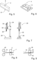
- a receiving opening 8 is used for the use of a clamping bolt, not shown here, with which the first welding jaw 2 is placed in a welding jaw receptacle 26 (cf 7 ) is attached to a machine that applies the prestressing force F v and the impulse force F i to the first welding jaw 2 .
- FIG. 6 shows a schematic perspective view of an embodiment of a second welding jaw 4 according to the invention with a flat effective area 6. This is mounted on a welding jaw holder 28 (cf 7 ) attached.
- FIG. 7 shows a schematic view of two sides of an embodiment of an impact press 20 with which the sealing method according to the invention can be carried out. It is particularly advantageous that such a percussion press 20 can be operated without electrical energy and purely manually, in particular designed as a spring percussion press according to the illustrated embodiment.
- the force required for the feed movement over the infeed path s z as well as for the prestressing force F v and the impulse force F i are applied by the operator via an operating lever 24 .
- the weld seam 12 is produced between the second welding jaw 4, on which the plastic films 10 lie, and the first welding jaw 2, which is fastened in a first welding jaw receptacle 26.
- the operating lever 24 is moved and the first sealing jaw receptacle 26 is moved towards the second sealing jaw receptacle 28 via a feed device 32 until the first sealing jaw 2 inserted in the first sealing jaw receptacle 26 touches the plastic films 10 .
- the sealed plastic films 10 in the area of the weld seam 12 and along these are additionally and simultaneously separated. This can be advantageous if, for example, a pack is to be closed by the weld seam 12 and at the same time separated from a subsequent pack.
- FIG 8 shows a schematic side view of an embodiment of a continuous web running process in which the plastic film 10 runs off a film roll 40 .
- the plastic film 10 runs between the first sealing jaw 2 and the second sealing jaw 4, where the production of the weld seam 12 (the weld seam 12 is not yet formed in the illustration) takes place.
- precautions must be taken to ensure the continuity of the web travel process even during the effects of the pretensioning force in particular, but also the impact impulse. This can be implemented, for example, by carrying along and returning the device 1 in cycles or by means of a web storage device in front of the device 1 .
- FIG. 9 shows a schematic side view of a further embodiment of a continuous web running process.
- the pretensioning force is applied by pretensioning rollers 42, between which the plastic film 10 runs.
- a device for generating impulses 30 acts on one or both pretensioning rollers 42, so that the weld seam 12 is produced.
Landscapes
- Engineering & Computer Science (AREA)
- Mechanical Engineering (AREA)
- Lining Or Joining Of Plastics Or The Like (AREA)
Abstract
Description
- Die Erfindung betrifft ein Verfahren und eine Vorrichtung zum Verbinden von Kunststofffolien durch thermisches Fügen, wobei die Kunststofffolien zwischen Schweißbacken entlang einer Schweißnaht verbunden werden. Die Erfindung betrifft weiterhin eine Verwendung einer Schlagpresse.
- Ein wichtiges Anwendungsgebiet für das thermische Fügen ist das Herstellen und Verschließen von Verpackungen aus Kunststofffolie, z. B. Schlauchbeutel, wobei der Vorgang dort auch als Siegeln bzw. Heißsiegeln bezeichnet wird. Neben Verfahren und Vorrichtungen zum Verbinden von Kunststofffolien durch thermisches Fügen mittels beheizter Schweißbacken, auch als Siegelbacken bezeichnet, die Teile der Kunststofffolien aufschmelzen, gibt es vielfältige Bestrebungen, auf beheizte Schweißbacken zu verzichten. Dafür sind vor allem zwei Gründe ausschlaggebend, das Verpacken wärmeempfindlicher Güter ohne Eintrag zusätzlicher Wärmeenergie und die Verringerung des Energieverbrauchs.
- Durch das thermische Fügen mittels Ultraschall kann auf beheizte Schweißbacken verzichtet werden, weil die thermische Wirkung in den zu verschweißenden Folien selbst durch den Energieeintrag der Ultraschallschwingungen hervorgerufen wird. Auf diesem Effekt beruhen die Lösungen zum Ultraschallsiegeln, die beispielsweise die Druckschriften
DE 699 26 758 T2 ,DE 10 2009 046 319 A1 undDE 10 2017 121 572 A1 , hier in Kombination mit dem Heißsiegeln, beschreiben. Allerdings sind die für das Ultraschallsiegeln erforderliche maschinentechnische Ausrüstung und die Erzeugung des Ultraschalls sehr aufwändig. - Auch andere Verfahren zur Bearbeitung von Kunststofffolien, wie z. B. das Trennen von Kunststofffolien durch einen Schlagimpuls mittels einer Folienstanze gemäß der Druckschrift
DE 10 2015 211 622 A1 , sind nicht geeignet, die Kunststofffolien miteinander zu verbinden und eine Schweißnaht auszubilden oder erreichen dies nur, wenn zugleich die Folien an der Schweißnaht getrennt werden. - Es ist daher die Aufgabe der vorliegenden Erfindung, ein robustes, unaufwändiges Verfahren und eine einfache Vorrichtung zum Verbinden von Kunststofffolien durch thermisches Fügen anzubieten, wobei die Kunststofffolien zwischen Schweißbacken entlang einer Schweißnaht verbunden werden. Eine weitere Aufgabe der Erfindung sieht die Verwendung einer Schlagpresse vor.
- Die Aufgabe wird gelöst durch ein Verfahren zum Verbinden von Kunststofffolien durch thermisches Fügen, wobei die Kunststofffolien zwischen Schweißbacken entlang einer Schweißnaht verbunden werden. Nach der Erfindung werden die übereinander angeordneten Kunststofffolien in einem ersten Schritt zwischen einem Paar der Schweißbacken mit einer Vorspannkraft gegeneinander gedrückt und in einem zweiten Schritt wirkt ein Schlagimpuls, weitergeleitet durch wenigstens eine der Schweißbacken, mit zumindest einer ersten Intensität auf die Kunststofffolien ein und die Schweißnaht wird ausgebildet. Es ist nicht erforderlich, das Verfahren mit vorgeheizten bzw. vorgewärmten Kunststofffolien durchzuführen. Wegen des schnellen Temperaturanstiegs hat die Materialtemperatur kaum einen Einfluss. Ebenso verhält es sich mit den Schweißbacken, die nicht vorgeheizt bzw. nicht vorgewärmt sein müssen, da die zum Schweißen erforderliche Temperatur in sehr kurzer Zeit während des Impulses in der Folie selbst erzeugt wird.
- Bei der Weiterleitung des Schlagimpulses wird von Schallgeschwindigkeit und von einer Stoßimpulszeit von unter 10 ms, vorzugsweise 5 ms, ausgegangen. Für den Impuls Stahl/Stahl wurde für die Strecke von 10 cm eine Zeit von 0,25 ms errechnet. Mit dem Schlagimpuls wird eine mit dem Ultraschallsiegeln vergleichbare Wirkung auf vergleichbare Materialien erzielt, allerdings wird anstelle einer großen Zahl von Impulsen geringer Amplitude nur ein einziger Impuls aufgebracht, der Schlagimpuls gemäß der Erfindung. Bei beiden Verfahren, bei Einsatz von Ultraschall und eines Schlagimpulses, erfolgt die für das thermische Fügen erforderliche Temperaturerhöhung durch eine physikalisch-chemische Wirkung im Kunststoff, aus dem die zu fügenden Folien bestehen. Zugleich werden die Vorteile verwirklicht, insbesondere der fehlende Wärmeeintrag, die auch für den Einsatz des Ultraschallsiegelns ausschlaggebend sind, jedoch ohne dass die aufwändige Anlagentechnik mit Ultraschallerzeugung und Sonotrode erforderlich ist.
- Nach einer vorteilhaften Ausgestaltung des Verfahrens erfolgt der Schlagimpuls anstelle der ersten Intensität mit einer zweiten Intensität, die höher ist als die erste Intensität, sodass zusammen mit dem thermischen Fügen auch ein Trennen der Kunststofffolien in und entlang der Schweißnaht erfolgt. Die Schweißnaht selbst wird dabei längs geteilt.
- Der Schlagimpuls wird insbesondere durch Federkraft, Fallgewicht oder einen mechanischen Antrieb hervorgerufen. Eine Möglichkeit des mechanischen Antriebs besteht in dessen Ausführung als Kurvenscheibengetriebe, mit dem besonders schnelle Bewegungen verzögerungsfrei und mit exakter Amplitude gesteuert werden können. Vor allem die Federkraft und das Fallgewicht können manuell in die Position gebracht werden, wo sie Kraft erzeugen, sodass das erfindungsgemäße Verfahren ohne externe Energiezufuhr ausgeführt werden kann.
- Der Schlagimpuls wird durch die obere Schweißbacke oder, alternativ hierzu, durch beide Schweißbacken, die gegeneinander wirken, aufgebracht. Insbesondere bei gegeneinander wirkenden Schweißbacken können diese auch für einen schnelllaufende Prozess, beispielsweise in einer Schlauchbeutelmaschine, z. B. mit 100 Takten pro Minute, verwendet und in diesen integriert werden. Dabei können die Schweißbacken als Rollen, die beispielsweise zugleich als Vorschubrollen fungieren, ausgeführt sein, die die Vorspannkraft Fv aufbringen, während die Impulskraft Fi durch einen Schlag auf die Rollen auf die Kunststofffolien übertragen wird.
- Die Aufgabe wir ebenfalls gelöst durch eine Vorrichtung zum Verbinden von Kunststofffolien durch thermisches Fügen, wobei die Kunststofffolien zwischen Schweißbacken entlang einer Schweißnaht verbunden werden. Nach der Erfindung umfasst die Vorrichtung ein Paar Schweißbacken, zwischen denen beim Siegelvorgang die übereinander angeordneten Kunststofffolien angeordnet werden. Die Schweißbacken werden mittels einer Vorspannkraft gegeneinander gedrückt. Eine Antriebsvorrichtung kann einen Schlagimpuls mit wenigstens einer ersten Intensität in wenigstens eine der Schweißbacken eintragen, der auf die Kunststofffolien in dem Moment des thermischen Fügens durch den Schlagimpuls einwirkt. In der Folge wird die Schweißnaht in einem entsprechend der Länge der herzustellenden Schweißnaht längs ausgedehnten Wirkbereich der Schweißbacken ausgebildet.
- Bei der bevorzugten Ausführungsform besteht das Paar Schweißbacken aus wenigstens einer ersten Schweißbacke mit einem Wirkbereich mit profiliertem Querschnitt. Es hat sich weiterhin als vorteilhaft erwiesen, wenn das Paar Schweißbacken eine zweite Schweißbacke mit flächigem Wirkbereich oder mit profiliertem Querschnitt umfasst.
- Der profilierte Querschnitt ist an der Wirkstelle, die mit den zu verschweißenden Folien während des Schweißvorgangs in Kontakt steht, nach einer ersten Ausführungsform als ein Radius Rx, bevorzugt mit Rx = 4 bis 10 mm, ausgebildet. Der profilierte Querschnitt ist alternativ dazu als von zwei Radien Ry, bevorzugt mit Ry = 1 bis 4 mm, beidseits begrenztes Flachprofil mit einer Breite a, bevorzugt a = 0,1 bis 0,4 mm, ausgebildet. Nach einer weiteren Alternative ist der profilierte Querschnitt keilförmig mit einem Winkel α, bevorzugt α = 2 bis 5°, gemessen gegen den flächigen Wirkbereich der zweiten Schweißbacke, der in der Regel waagerecht, jedenfalls senkrecht zur Schlagrichtung ausgerichtet ist. Die Keilspitze des keilförmigen Querschnitts ist als Radius Rz, bevorzugt mit Rz = 1 bis 4 mm, ausgebildet.
- Nach einer vorteilhaften Ausführungsform sind die erste und/oder die zweite Schweißbacke als Rollwerkzeug zur Wirkung in einem Bahnlaufprozess mit fortlaufendem Vorschub ausgeführt. Die erfindungsgemäße Vorrichtung ist daher zum Einbau in Verpackungsanlagen, wobei auch etablierte Technik zum Siegeln ersetzt werden kann, geeignet.
- Es hat sich als vorteilhaft erwiesen, wenn das Paar Schweißbacken aus gehärtetem Stahl mit geschliffener Oberfläche ausgeführt ist. Weiterhin enthält jede der Schweißbacken Elemente zur Befestigung an der Antriebsvorrichtung.
- Die Antriebsvorrichtung wirkt nach einer ersten Ausführungsform auf die erste Schweißbacke oder nach einer zweiten Ausführungsform auf die erste und die zweite Schweißbacke. Die Antriebsvorrichtung zur Erzeugung des Schlagimpulses weist eine Feder, ein Fallgewicht oder ein mechanisches Getriebe auf. Das mechanische Getriebe ist nach einer vorteilhaften Ausgestaltung ein Kurvenscheibengetriebe, dessen Vorteile oben bereits erläutert wurden.
- Die Aufgabe wird ebenfalls gelöst durch eine Verwendung einer Schlagpresse als Antriebsvorrichtung für eine Vorrichtung, wie sie zuvor beschrieben wurde. Pneumatische Schlagpressen eignen sich nicht nur zum Prägen von Metallen, sondern auch zum Markieren von Kunststoffen oder ähnlichen Produkten. Auch in der Pharmaindustrie werden kleine Schlagpressen zum Prägen von Medikamentenschachteln häufig verwendet. Mit einer Schlagfeder kann die gewünschte Schlagstärke genau eingestellt werden und man erreicht - wenn einmal justiert - bei jedem Prägevorgang im gleichen Material die gleichen Prägeergebnisse.
- Der Vorspanneffekt, der auch für das erfindungsgemäße Verfahren eine entscheidende Rolle spielt, erlaubt eine exakte Positionierung des Werkstücks, Deformierungen werden verhindert. Mittels eines Spannsystems können unterschiedliche Prägewerkzeuge wie Maschinenstempel, Maschinentypenhalter und Prägewerke in diesen Maschinen eingespannt werden. Eine beispielhafte Prägepresse besitzt eine Schlagkraft von 6 kN.
- Gegenüber den etablierten Siegelverfahren wie Wärme-Kontaktsiegeln oder Ultraschallsiegeln bietet das mit der Erfindung vorgeschlagene Siegelverfahren folgende Vorteile:
- kalte Werkzeuge, adiabatischer Fügeprozess,
- Verwendung bei wärmeempfindlichen Produkten möglich,
- sehr kostengünstige und robuste Anlagen- und Werkzeugtechnik,
- rein mechanische und handbetriebene Lösungen umsetzbar (Federvorspannung),
- extrem kurze Prozesszeit,
- kleinste Nahtbreiten realisierbar,
- Fügen oder Füge-Trenn-Kombination mit demselben Werkzeug umsetzbar,
- für recyclingfähige Monofolien oder Monoverbundfolien geeignet,
- Übliche Verpackungsformen (Siegelrandbeutel, Schlauchbeutel) umsetzbar,
- sehr geringer Energiebedarf, dadurch sehr hoher energetischer Wirkungsgrad.
- Beim Wärmeimpulsfügen für einer PP-Folie mit einer Foliendicke von 20 ... 100 µm ist ein elektrisch erzeugter Wärmeimpuls von 0,8 Sekunden bei 165°C notwendig. Das entspricht an einer Schweißzange einem Energieverbrauch von 200 J. Für das Fügen mit dem erfindungsgemäßen Verfahren ist dem gegenüber nur ein Energiebedarf von 5 J erforderlich. Das entspricht einer Energieeinsparung von 97,5%.
- Aus den zuvor genannten Vorteilen ergeben sich in den folgende vorteilhafte Anwendungsgebiete:
- Verpackungsprozess mit Kunststofffolien (technische Produkte, Lebensmittel, Medizinprodukte) sowohl für schnelllaufende Serienanwendungen als auch für Einzelprozesse bei dezentraler Produktion,
- Einsatz für kontinuierliche Prozesse aufgrund hoher Prozessgeschwindigkeit,
- Einsatz bei recyclingfähigen und kompostierbaren Folien,
- Anwendungen zum Versiegeln ohne elektrische Energie mittels Federvorspannung für mobilen Einsatz, Medizintechnik für Entwicklungshilfe (Einschweißen medizinischer Proben vor Ort), Katastrophenhilfe (Verschließen von Sandsäcken),
- Verpackung in staubbelasteter Umgebung.
- Anhand der Beschreibung von Ausführungsbeispielen und ihrer Darstellung in den zugehörigen Zeichnungen wird die Erfindung nachfolgend näher erläutert. Es zeigen:
-
Fig. 1 : schematisch eine Ansicht eines Verfahrensablaufs des erfindungsgemäßen Verfahren zum Verbinden von Kunststofffolien durch thermisches Fügen; -
Fig. 2 : schematisch eine perspektivische Ansicht einer Ausführungsform einer erfindungsgemäßen Schweißbacke mit einem Wirkbereich mit als Radius profiliertem Querschnitt; -
Fig. 3 : schematisch eine perspektivische Ansicht einer Ausführungsform einer erfindungsgemäßen Schweißbacke mit einem Wirkbereich mit eben profiliertem Querschnitt, begrenzt durch zwei Radien; -
Fig. 4 : schematisch eine perspektivische Ansicht einer Ausführungsform einer erfindungsgemäßen Schweißbacke mit einem Wirkbereich mit flachwinklig profiliertem Querschnitt; -
Fig. 5 : schematisch eine perspektivische Ansicht einer Ausführungsform einer erfindungsgemäßen ersten Schweißbacke mit einem Wirkbereich mit eben profiliertem Querschnitt; -
Fig. 6 : schematisch eine perspektivische Ansicht einer Ausführungsform einer erfindungsgemäßen zweiten Schweißbacke mit einem ebenen Wirkbereich; -
Fig. 7 : schematisch in zwei Ansichten eine Ausführungsform einer Schlagpresse; -
Fig. 8 : schematisch in Seitenansicht eine Ausführungsform eines kontinuierlichen Bahnlaufprozesses und -
Fig. 9 : schematisch in zwei Ansichten eine weitere Ausführungsform eines kontinuierlichen Bahnlaufprozesses. -
Fig. 1 zeigt schematisch eine Ansicht eines Verfahrensablaufs des erfindungsgemäßen Verfahrens zum Verbinden von Kunststofffolien 10 durch thermisches Fügen. Der Verfahrensablauf wird in 3 Schritten von links beginnend dargestellt. Zunächst wird eine erste Schweißbacke 2 über den Zustellweg sz hinweg bis zur Oberfläche der Kunststofffolien 10 in Pfeilrichtung bewegt, bis ein Wirkprofil 6 die Kunststofffolien 10 berührt. Die beiden durch eine Schweißnaht zu verbindenden Kunststofffolien 10 liegen dabei auf der Oberfläche der zweiten Schweißbacke 4. - In einem zweiten Schritt wird die erste Schweißbacke 2 mit einer Vorspannkraft Fv gegen die Kunststofffolien 10 gedrückt. Unter der so geschaffenen Vorlast wird im dritten Schritt die Impulskraft Fi aufgebracht, die zum Ausbilden der Schweißnaht 12 führt.
- Bei der dargestellten Ausgestaltung des erfindungsgemäßen Verfahrens bleiben die Kunststofffolien 10 im Bereich der Schweißnaht 12 miteinander verbunden. Ist jedoch auch möglich, durch Wahl einer höheren Impulskraft Fi zu erreichen, dass an der Schweißnaht 12 zugleich ein Trennen der Kunststofffolien 10 erfolgt, sodass zwei miteinander durch die Schweißnaht 12 verbundene Kunststofffolien vorliegen, die jedoch im Bereich der Schweißnaht 12 quer getrennt sind.
-
Fig. 2 zeigt schematisch eine perspektivische Ansicht einer Ausführungsform einer erfindungsgemäßen ersten Schweißbacke 2 mit einem als Radius Rx ausgeführten, profilierten Querschnitt, der ein Wirkprofil 6 ausbildet. Bei einer Foliendicke von 70 µm beträgt der bevorzugte Radius Rx = 4 bis 10 mm, wobei eine gute Werkstoffbindung an der Schweißstelle und eine dichte Schweißnaht erreicht wird. -
Fig. 3 zeigt schematisch eine perspektivische Ansicht einer Ausführungsform einer erfindungsgemäßen Schweißbacke 2 mit einem eben profilierten Querschnitt, begrenzt durch zwei Radien Ry, der ein Wirkprofil 6 ausbildet. Bei einer Foliendicke von 70 µm beträgt der bevorzugte Radius Ry = 1 bis 4 mm und das ebene Profil hat eine Breite a = 0,1 bis 0,5 mm. -
Fig. 4 zeigt schematisch eine perspektivische Ansicht einer Ausführungsform einer erfindungsgemäßen Schweißbacke 2 mit einem flachwinklig profilierten Querschnitt, der ein Wirkprofil 6 ausbildet. Die Spitze des Winkels weist einen Radius Rz auf. Bei einer Foliendicke von 70 µm beträgt der bevorzugte Radius Rx = 4 bis 10 mm und der bevorzugte Winkel α = 2 bis 5°. -
Fig. 5 zeigt schematisch eine perspektivische Ansicht einer Ausführungsform einer erfindungsgemäßen ersten Schweißbacke 2 mit einem Wirkbereich 6 mit eben profiliertem Querschnitt. Eine Aufnahmeöffnung 8 dient dem Einsatz eines hier nicht dargestellten Einspannbolzen, mit dem die erste Schweißbacke 2 in einer Schweißbackenaufnahme 26 (vergleicheFig. 7 ) einer Maschine befestigt wird, die die Vorspannkraft Fv und die Impulskraft Fi auf die erste Schweißbacke 2 aufbringt. -
Fig. 6 zeigt schematisch eine perspektivische Ansicht einer Ausführungsform einer erfindungsgemäßen zweiten Schweißbacke 4 mit einem ebenen Wirkbereich 6. Dieses wird auf einer Schweißbackenaufnahme 28 (vergleicheFig. 7 ) befestigt. -
Fig. 7 zeigt schematisch in Ansicht zwei Seiten eine Ausführungsform einer Schlagpresse 20, mit der das erfindungsgemäße Siegelverfahren ausgeführt werden kann. Besonders vorteilhaft ist, dass eine solche Schlagpresse 20 ohne Elektroenergie und rein manuell betrieben werden kann, insbesondere ausgeführt als Federschlagpresse gemäß dem dargestellten Ausführungsbeispiel. Die erforderliche Kraft für die Vorschubbewegung über den Zustellweg sz sowie auch für die Vorspannkraft Fv und die Impulskraft Fi werden durch den Bediener über einen Bedienhebel 24 aufgebracht. - Entsprechend der Darstellung in
Fig. 1 wird zwischen der zweiten Schweißbacke 4, auf dem die Kunststofffolien 10 aufliegen, und der ersten Schweißbacke 2, dass in einer ersten Schweißbackenaufnahme 26 befestigt ist, die Schweißnaht 12 hergestellt. Dazu wird der Bedienhebel 24 bewegt und über eine Vorschubeinrichtung 32 die erste Schweißbackenaufnahme 26 auf die zweite Schweißbackenaufnahme 28 zubewegt, bis das in der ersten Schweißbackenaufnahme 26 eingesetzte erste Schweißbacke 2 die Kunststofffolien 10 berührt. - Durch weitere Bewegung des Bedienhebels 24 wird die erforderliche Vorspannkraft Fv und nach weiterer Bewegung des Bedienhebels 24, wobei eine Feder gespannt wird, die Impulskraft Fi durch Auslösen der Impulserzeugung 30 auf die Kunststofffolien 10 aufgebracht. Die Schweißnaht 12 ist damit im Bereich einer Kontaktzone zwischen der ersten Schweißbacke 2 und der zweiten Schweißbacke 4 hergestellt. Der Rückhub der zweiten Schweißbackeaufnahme 26 durch Gegenbewegung des Bedienhebels 24 führt zur Freigabe der gesiegelten, miteinander verschweißten Kunststofffolien 10.
- In Abhängigkeit vom gewünschten Ergebnis und von der eingestellten Höhe der Impulskraft Fi können die gesiegelten Kunststofffolien 10 im Bereich der Schweißnaht 12 und entlang dieser zusätzlich und gleichzeitig getrennt werden. Dies kann vorteilhaft sein, wenn beispielsweise eine Packung durch die Schweißnaht 12 verschlossen und zugleich von einer nachfolgenden Packung getrennt werden soll.
-
Fig. 8 zeigt schematisch in Seitenansicht eine Ausführungsform eines kontinuierlichen Bahnlaufprozesses, bei dem die Kunststofffolie 10 von einer Folienrolle 40 abläuft. In der Vorrichtung 1 zum Verbinden von Kunststofffolien 10 durch thermisches Fügen läuft die Kunststofffolie 10 zwischen der ersten Schweißbacke 2 und der zweiten Schweißbacke 4 hindurch, wo die Herstellung der Schweißnaht 12 (in der Darstellung ist die Schweißnaht 12 noch nicht gebildet) erfolgt. Es müssen jedoch Vorkehrungen getroffen werden, um die Kontinuität des Bahnlaufprozesses auch während des Einwirkens vor allem der Vorspannkraft, aber auch des Schlagimpulses, sicherzustellen. Dies kann beispielsweise durch ein taktweises Mitführen und Rückführen der Vorrichtung 1 oder durch einen Bahnspeicher vor der Vorrichtung 1 realisiert werden. -
Fig. 9 zeigt schematisch in Seitenansicht eine weitere Ausführungsform eines kontinuierlichen Bahnlaufprozesses. Durch Vorspannrollen 42, zwischen denen die Kunststofffolie 10 hindurchläuft, wird die Vorspannkraft aufgebracht. Eine Einrichtung zur Impulserzeugung 30 wirkt auf eine oder beide Vorspannrollen 42, sodass die Schweißnaht 12 erzeugt wird. -
- 1
- Vorrichtung
- 2
- erste Schweißbacke
- 4
- zweite Schweißbacke
- 6, 6'
- Wirkbereich, Wirkprofil
- 8
- Aufnahmeöffnung
- 10
- Kunststofffolie
- 12
- Schweißnaht
- 20
- Schlagpresse
- 22
- Ständer
- 24
- Bedienhebel
- 26
- erste Schweißbackenaufnahme
- 28
- zweite Schweißbackenaufnahme
- 30
- (Einrichtung zur) Impulserzeugung
- 32
- Vorschubeinrichtung
- 40
- Folienrolle
- 42
- Rollwerkzeug, Vorspannrolle
- a
- Wirkprofilbreite
- Rx
- erster Wirkprofilradius
- Ry
- zweiter Wirkprofilradius
- Rz
- dritter Wirkprofilradius
- Fv
- Vorspannkraft
- Fi
- Impulskraft, Intensität des Schlagimpulses
- sz
- Zustellweg
Claims (15)
- Verfahren zum Verbinden von Kunststofffolien (10) durch thermisches Fügen, wobei die Kunststofffolien (10) zwischen Schweißbacken (2, 4) entlang einer Schweißnaht (12) verbunden werden, dadurch gekennzeichnet, dass die übereinander angeordneten Kunststofffolien (10) in einem ersten Schritt zwischen einem Paar der Schweißbacken (2, 4) mit einer Vorspannkraft Fv gegeneinander gedrückt werden und in einem zweiten Schritt ein Schlagimpuls, weitergeleitet durch wenigstens eine der Schweißbacken (2, 4), mit zumindest einer ersten Intensität (Fi1) auf die Kunststofffolien (10) einwirkt und die Schweißnaht (12) ausgebildet wird.
- Verfahren nach Anspruch 1, wobei der Schlagimpuls mit einer zweiten Intensität (Fi2) anstelle der ersten Intensität (Fi1) erfolgt, wobei die zweite Intensität (Fi2) höher ist als die erste Intensität (Fi1), mit der Folge, dass zusammen mit dem thermischen Fügen auch ein Trennen der Kunststofffolien (10) in und entlang der Schweißnaht (12) erfolgt.
- Verfahren nach Anspruch 1 oder 2, wobei der Schlagimpuls durch Federkraft, Fallgewicht oder einen mechanischen Antrieb hervorgerufen wird.
- Verfahren nach einem der vorherigen Ansprüche, wobei der Schlagimpuls durch die obere Schweißbacke (2) oder durch beide Schweißbacken (2, 4), die gegeneinander wirken, aufgebracht wird.
- Verfahren nach Anspruch 4, wobei die gegeneinander wirkenden Schweißbacken (2, 4) in einem in einem schnelllaufenden Prozess verwendet werden.
- Vorrichtung zum Verbinden von Kunststofffolien (10) durch thermisches Fügen, wobei die Kunststofffolien (10) zwischen Schweißbacken (2, 4) entlang einer Schweißnaht (12) verbunden werden, dadurch gekennzeichnet, dass die Vorrichtung (1) ein Paar der Schweißbacken (2, 4) umfasst, zwischen denen beim Siegelvorgang die übereinander angeordneten Kunststofffolien (10) angeordnet werden, wobei die Schweißbacken (2, 4) mittels einer Vorspannkraft (Fv) gegeneinander gedrückt werden und eine Einrichtung zur Impulserzeugung (30) während des thermischen Fügens einen Schlagimpuls mit wenigstens einer ersten Intensität (Fi1) in wenigstens einer der Schweißbacken (2, 4) einträgt, der auf die Kunststofffolien (10) einwirkt und die Schweißnaht (12) in einem entsprechend der Länge der herzustellenden Schweißnaht (12) längs ausgedehnten Wirkbereich der Schweißbacken (2, 4) ausgebildet wird.
- Vorrichtung nach Anspruch 6, wobei das Paar Schweißbacken (2, 4) aus wenigstens einer ersten Schweißbacke (2) mit einem Wirkbereich mit profiliertem Querschnitt (6') besteht.
- Vorrichtung nach Anspruch 7, wobei das Paar Schweißbacken (2, 4) eine zweite Schweißbacke (4) mit flächigem Wirkbereich (6) oder mit profiliertem Querschnitt (6') umfasst.
- Vorrichtung nach Anspruch 6 oder 7, wobei der profilierte Querschnitt (6') als ein Radius Rx ausgebildet ist.
- Vorrichtung nach Anspruch 6 oder 7, wobei der profilierte Querschnitt (6') als von zwei Radien Ry begrenztes Flachprofil mit einer Breite a ausgebildet ist.
- Vorrichtung nach Anspruch 6 oder 7, wobei der profilierte Querschnitt (6') keilförmig mit einem Winkel α gegen den flächigen Wirkbereich der zweiten Schweißbacke (4), deren Keilspitze als Radius Rz ausgebildet ist.
- Vorrichtung nach Anspruch 6 bis 11, wobei die erste und/oder die zweite Schweißbacke (2, 4) als Rollwerkzeug (42) zur Wirkung in einem Bahnlaufprozess mit fortlaufendem Vorschub ausgeführt sind.
- Vorrichtung nach Anspruch 6 bis 12, wobei die Einrichtung zur Impulserzeugung (30) nur auf die erste Schweißbacke (2) oder die erste und die zweite Schweißbacke (2, 4) zugleich wirkt.
- Vorrichtung nach Anspruch 6 bis 13, wobei die Einrichtung zur Impulserzeugung (30) eine Feder, ein Fallgewicht oder ein mechanisches Getriebe aufweist.
- Verwendung einer Schlagpresse (20) als Antriebsvorrichtung für eine Vorrichtung nach einem der Ansprüche 7 bis 14.
Priority Applications (7)
| Application Number | Priority Date | Filing Date | Title |
|---|---|---|---|
| EP22151636.2A EP4212310A1 (de) | 2022-01-14 | 2022-01-14 | Verfahren und vorrichtung zum verbinden von kunststofffolien durch thermisches fügen sowie verwendung einer schlagpresse |
| JP2024539478A JP2025500573A (ja) | 2022-01-14 | 2023-01-16 | 熱接合によってプラスチックフィルムを接続するための溶接シーム、方法、及びデバイスと、ブロー鍛造プレスの使用法 |
| EP23700852.9A EP4463308A1 (de) | 2022-01-14 | 2023-01-16 | Schweissnaht, verfahren und vorrichtung zum verbinden von kunststofffolien durch thermisches fügen sowie verwendung einer schlagpresse |
| US18/728,084 US20250100230A1 (en) | 2022-01-14 | 2023-01-16 | Weld Seam, Method and Device for Connecting Plastics Films by Thermal Joining, and Use of a Blow-Forging Press |
| CN202380017238.2A CN118660806A (zh) | 2022-01-14 | 2023-01-16 | 通过热接合来连接塑料薄膜的焊缝、方法和装置以及吹塑压力机的用途 |
| PCT/EP2023/050820 WO2023135280A1 (de) | 2022-01-14 | 2023-01-16 | Schweissnaht, verfahren und vorrichtung zum verbinden von kunststofffolien durch thermisches fügen sowie verwendung einer schlagpresse |
| KR1020247027310A KR20240134377A (ko) | 2022-01-14 | 2023-01-16 | 열 접합에 의해 플라스틱 필름을 연결하기 위한 용접 심, 방법, 및 장치, 및 블로우 단조 프레스의 사용 |
Applications Claiming Priority (1)
| Application Number | Priority Date | Filing Date | Title |
|---|---|---|---|
| EP22151636.2A EP4212310A1 (de) | 2022-01-14 | 2022-01-14 | Verfahren und vorrichtung zum verbinden von kunststofffolien durch thermisches fügen sowie verwendung einer schlagpresse |
Publications (1)
| Publication Number | Publication Date |
|---|---|
| EP4212310A1 true EP4212310A1 (de) | 2023-07-19 |
Family
ID=79730462
Family Applications (2)
| Application Number | Title | Priority Date | Filing Date |
|---|---|---|---|
| EP22151636.2A Pending EP4212310A1 (de) | 2022-01-14 | 2022-01-14 | Verfahren und vorrichtung zum verbinden von kunststofffolien durch thermisches fügen sowie verwendung einer schlagpresse |
| EP23700852.9A Pending EP4463308A1 (de) | 2022-01-14 | 2023-01-16 | Schweissnaht, verfahren und vorrichtung zum verbinden von kunststofffolien durch thermisches fügen sowie verwendung einer schlagpresse |
Family Applications After (1)
| Application Number | Title | Priority Date | Filing Date |
|---|---|---|---|
| EP23700852.9A Pending EP4463308A1 (de) | 2022-01-14 | 2023-01-16 | Schweissnaht, verfahren und vorrichtung zum verbinden von kunststofffolien durch thermisches fügen sowie verwendung einer schlagpresse |
Country Status (6)
| Country | Link |
|---|---|
| US (1) | US20250100230A1 (de) |
| EP (2) | EP4212310A1 (de) |
| JP (1) | JP2025500573A (de) |
| KR (1) | KR20240134377A (de) |
| CN (1) | CN118660806A (de) |
| WO (1) | WO2023135280A1 (de) |
Citations (7)
| Publication number | Priority date | Publication date | Assignee | Title |
|---|---|---|---|---|
| US3809306A (en) * | 1970-06-23 | 1974-05-07 | Usm Corp | Apparatus for rounding welded edge seams |
| US4743333A (en) * | 1986-07-31 | 1988-05-10 | Frederick Forthmann | Splicing device for heat sealable material |
| DE69926758T2 (de) | 1998-03-23 | 2006-03-30 | Shikoku Kakoki Co., Ltd. | Ultraschall-siegler |
| DE102009046319A1 (de) | 2009-11-03 | 2011-05-05 | Robert Bosch Gmbh | Vorrichtung und Verfahren zum Siegeln einer Folie |
| EP2441570A2 (de) * | 2010-10-13 | 2012-04-18 | MULTIVAC Sepp Haggenmüller GmbH & Co KG | Verfahren und Kammermaschine zum Versiegeln von Verpackungsmaterial |
| DE102015211622A1 (de) | 2015-06-23 | 2016-12-29 | Multivac Sepp Haggenmüller Se & Co. Kg | Tiefziehverpackungsmaschine mit Folienstanze |
| DE102017121572A1 (de) | 2016-09-20 | 2018-03-22 | Gerhard Schubert Gmbh | Verfahren und Vorrichtung zum Herstellen von Schlauchbeuteln |
Family Cites Families (9)
| Publication number | Priority date | Publication date | Assignee | Title |
|---|---|---|---|---|
| US2510383A (en) * | 1945-11-15 | 1950-06-06 | Pye Ltd | Method of cutting or trimming thermoplastic materials |
| US3097124A (en) * | 1957-08-30 | 1963-07-09 | Denenberg Maurice | Insulating wall board and method of forming same |
| DE1778008B1 (de) * | 1968-03-20 | 1971-08-26 | Ver Schuhmasch Gmbh | Antriebs und steuerungssystem fuer eine hochfrequenz schweiss stanzmaschine |
| US4240865A (en) * | 1979-06-25 | 1980-12-23 | Interlake, Inc. | Apparatus and method for applying plastic strap |
| US4426901A (en) * | 1981-11-16 | 1984-01-24 | The Firestone Tire & Rubber Company | Crush cutter |
| ATE113239T1 (de) * | 1988-11-22 | 1994-11-15 | Mitsui Petrochemical Ind | Warm-schweissblatt und warm-schweissgerät. |
| CA2056675A1 (en) * | 1991-04-29 | 1992-10-30 | Karl M. Wilcox | Seal bar |
| KR100756411B1 (ko) * | 2005-09-08 | 2007-09-10 | 삼성전자주식회사 | 열압착 공구 및 이를 포함한 열압착 장치 |
| JP6965515B2 (ja) * | 2016-12-22 | 2021-11-10 | オムロン株式会社 | シールバー及び熱シール装置 |
-
2022
- 2022-01-14 EP EP22151636.2A patent/EP4212310A1/de active Pending
-
2023
- 2023-01-16 WO PCT/EP2023/050820 patent/WO2023135280A1/de not_active Ceased
- 2023-01-16 KR KR1020247027310A patent/KR20240134377A/ko active Pending
- 2023-01-16 CN CN202380017238.2A patent/CN118660806A/zh active Pending
- 2023-01-16 EP EP23700852.9A patent/EP4463308A1/de active Pending
- 2023-01-16 JP JP2024539478A patent/JP2025500573A/ja active Pending
- 2023-01-16 US US18/728,084 patent/US20250100230A1/en active Pending
Patent Citations (7)
| Publication number | Priority date | Publication date | Assignee | Title |
|---|---|---|---|---|
| US3809306A (en) * | 1970-06-23 | 1974-05-07 | Usm Corp | Apparatus for rounding welded edge seams |
| US4743333A (en) * | 1986-07-31 | 1988-05-10 | Frederick Forthmann | Splicing device for heat sealable material |
| DE69926758T2 (de) | 1998-03-23 | 2006-03-30 | Shikoku Kakoki Co., Ltd. | Ultraschall-siegler |
| DE102009046319A1 (de) | 2009-11-03 | 2011-05-05 | Robert Bosch Gmbh | Vorrichtung und Verfahren zum Siegeln einer Folie |
| EP2441570A2 (de) * | 2010-10-13 | 2012-04-18 | MULTIVAC Sepp Haggenmüller GmbH & Co KG | Verfahren und Kammermaschine zum Versiegeln von Verpackungsmaterial |
| DE102015211622A1 (de) | 2015-06-23 | 2016-12-29 | Multivac Sepp Haggenmüller Se & Co. Kg | Tiefziehverpackungsmaschine mit Folienstanze |
| DE102017121572A1 (de) | 2016-09-20 | 2018-03-22 | Gerhard Schubert Gmbh | Verfahren und Vorrichtung zum Herstellen von Schlauchbeuteln |
Also Published As
| Publication number | Publication date |
|---|---|
| CN118660806A (zh) | 2024-09-17 |
| EP4463308A1 (de) | 2024-11-20 |
| US20250100230A1 (en) | 2025-03-27 |
| WO2023135280A1 (de) | 2023-07-20 |
| KR20240134377A (ko) | 2024-09-09 |
| JP2025500573A (ja) | 2025-01-09 |
Similar Documents
| Publication | Publication Date | Title |
|---|---|---|
| DE3688074T2 (de) | Ultraschallschweissvorrichtung mit kontaktflaechen. | |
| EP3212381B1 (de) | Vorrichtung und verfahren zur herstellung von kunststoffbeuteln | |
| DE10323783A1 (de) | Ultraschall-Schweissvorrichtung | |
| DE3202022A1 (de) | Vorrichtung zur kontrolle der bearbeitungsschritte in einer bearbeitungsbahn von verpackungsmaschinen, insbesondere fuer blister-packungen oder dergleichen | |
| EP3419810B1 (de) | Umreifungsvorrichtung mit einer ultraschallschweisseinrichtung | |
| EP2858798B1 (de) | Vorrichtung und verfahren zum ausbrechen und nutzentrennen | |
| EP2812174B1 (de) | Verfahren und vorrichtung zur konfektionierung von schlauchbeuteln aus dünnen kunststofffolien mittels eines ultraschall-schweissverfahrens | |
| DE102020117463A1 (de) | Gegenwerkzeug, Ultraschallschweißmaschine sowie Verfahren zur Erzeugung einer Dicht- und Kosmetiknaht | |
| EP1645401A2 (de) | Verfahren und Vorrichtung zum Positionieren einer Schweissbacke | |
| EP0551244B1 (de) | Breitbandbinden von gestapeltem Packgut | |
| WO2000010795A1 (de) | Verfahren zur herstellung von heissiegel-verpackungen und ein werkzeug zur durchführung des verfahrens | |
| EP1539583B1 (de) | Verfahren und vorrichtung zur herstellung einer primären einzelverpackung eines wafers | |
| DE29912490U1 (de) | Rotative Ultraschall-Schweißvorrichtung | |
| WO2023135280A1 (de) | Schweissnaht, verfahren und vorrichtung zum verbinden von kunststofffolien durch thermisches fügen sowie verwendung einer schlagpresse | |
| WO1999015449A1 (de) | Bandzugantrieb in einer thermoformvorrichtung zur herstellung einer blister-folie | |
| DE102023100891A1 (de) | Klebenaht, Verfahren und Vorrichtung zum Verbinden von Werkstoffbahnen oder Werkstoffbögen mittels eines thermisch aktivierbaren Klebstoffs sowie Verwendung einer Schlagpresse | |
| EP3023224B1 (de) | Sonotrode, schweissvorrichtung mit sonotrode sowie dazugehöriges schweissverfahren | |
| DE102023100890A1 (de) | Trennrand, Verfahren und Vorrichtung zum Trennen von einem Kunststofffaser basierten Textil sowie Verwendung einer Schlagpresse | |
| EP1988043B1 (de) | Verfahren un Vorrichtung zum Vorfalten einer Materialbahn | |
| DE202013100866U1 (de) | Ultraschall-Schweißvorrichtung mit Sonotrode | |
| DE102019108245B4 (de) | Schweißrolleneinrichtung, System und Verfahren zum Erzeugen einer Luftpolsterfolie | |
| DE102005047507A1 (de) | Verfahren und Vorrichtung zum Verschließen von Kunststoffbeuteln | |
| DE102006021599B3 (de) | Vorrichtung zum gleichzeitigen Verpacken von Gegenständen | |
| EP1480885A1 (de) | Appliziervorrichtung f r unterschiedlich lange etiketten | |
| DE2911360A1 (de) | Verfahren und vorrichtung zum aufleimen oder -kleben von furnieren oder kunststoffolien auf platten und andere oberflaechen |
Legal Events
| Date | Code | Title | Description |
|---|---|---|---|
| PUAI | Public reference made under article 153(3) epc to a published international application that has entered the european phase |
Free format text: ORIGINAL CODE: 0009012 |
|
| STAA | Information on the status of an ep patent application or granted ep patent |
Free format text: STATUS: THE APPLICATION HAS BEEN PUBLISHED |
|
| AK | Designated contracting states |
Kind code of ref document: A1 Designated state(s): AL AT BE BG CH CY CZ DE DK EE ES FI FR GB GR HR HU IE IS IT LI LT LU LV MC MK MT NL NO PL PT RO RS SE SI SK SM TR |
|
| STAA | Information on the status of an ep patent application or granted ep patent |
Free format text: STATUS: REQUEST FOR EXAMINATION WAS MADE |
|
| 17P | Request for examination filed |
Effective date: 20240118 |
|
| RBV | Designated contracting states (corrected) |
Designated state(s): AL AT BE BG CH CY CZ DE DK EE ES FI FR GB GR HR HU IE IS IT LI LT LU LV MC MK MT NL NO PL PT RO RS SE SI SK SM TR |
|
| STAA | Information on the status of an ep patent application or granted ep patent |
Free format text: STATUS: EXAMINATION IS IN PROGRESS |
|
| 17Q | First examination report despatched |
Effective date: 20251007 |