EP4212238A1 - Sparger and reactor comprising same - Google Patents
Sparger and reactor comprising same Download PDFInfo
- Publication number
- EP4212238A1 EP4212238A1 EP22862402.9A EP22862402A EP4212238A1 EP 4212238 A1 EP4212238 A1 EP 4212238A1 EP 22862402 A EP22862402 A EP 22862402A EP 4212238 A1 EP4212238 A1 EP 4212238A1
- Authority
- EP
- European Patent Office
- Prior art keywords
- sparger
- pipe
- reactor
- main body
- monomer
- Prior art date
- Legal status (The legal status is an assumption and is not a legal conclusion. Google has not performed a legal analysis and makes no representation as to the accuracy of the status listed.)
- Pending
Links
- 239000000178 monomer Substances 0.000 claims description 55
- 239000000463 material Substances 0.000 claims description 25
- 238000006243 chemical reaction Methods 0.000 description 34
- VGGSQFUCUMXWEO-UHFFFAOYSA-N Ethene Chemical compound C=C VGGSQFUCUMXWEO-UHFFFAOYSA-N 0.000 description 16
- 239000005977 Ethylene Substances 0.000 description 16
- 238000006384 oligomerization reaction Methods 0.000 description 15
- 239000002904 solvent Substances 0.000 description 13
- 239000006227 byproduct Substances 0.000 description 12
- 239000003054 catalyst Substances 0.000 description 11
- LIKMAJRDDDTEIG-UHFFFAOYSA-N 1-hexene Chemical compound CCCCC=C LIKMAJRDDDTEIG-UHFFFAOYSA-N 0.000 description 10
- KWKAKUADMBZCLK-UHFFFAOYSA-N 1-octene Chemical compound CCCCCCC=C KWKAKUADMBZCLK-UHFFFAOYSA-N 0.000 description 10
- 239000000047 product Substances 0.000 description 9
- 239000004711 α-olefin Substances 0.000 description 9
- 230000000694 effects Effects 0.000 description 8
- 238000000034 method Methods 0.000 description 8
- 230000008569 process Effects 0.000 description 8
- 239000012429 reaction media Substances 0.000 description 8
- 239000007788 liquid Substances 0.000 description 7
- 239000007795 chemical reaction product Substances 0.000 description 6
- TVMXDCGIABBOFY-UHFFFAOYSA-N n-Octanol Natural products CCCCCCCC TVMXDCGIABBOFY-UHFFFAOYSA-N 0.000 description 6
- 239000007921 spray Substances 0.000 description 6
- 230000003247 decreasing effect Effects 0.000 description 5
- 239000012530 fluid Substances 0.000 description 5
- 150000002430 hydrocarbons Chemical class 0.000 description 5
- 238000004519 manufacturing process Methods 0.000 description 5
- 125000004432 carbon atom Chemical group C* 0.000 description 4
- 229930195733 hydrocarbon Natural products 0.000 description 4
- UHOVQNZJYSORNB-UHFFFAOYSA-N Benzene Chemical compound C1=CC=CC=C1 UHOVQNZJYSORNB-UHFFFAOYSA-N 0.000 description 3
- IMNFDUFMRHMDMM-UHFFFAOYSA-N N-Heptane Chemical compound CCCCCCC IMNFDUFMRHMDMM-UHFFFAOYSA-N 0.000 description 3
- YXFVVABEGXRONW-UHFFFAOYSA-N Toluene Chemical compound CC1=CC=CC=C1 YXFVVABEGXRONW-UHFFFAOYSA-N 0.000 description 3
- 239000000376 reactant Substances 0.000 description 3
- 238000005507 spraying Methods 0.000 description 3
- 238000005829 trimerization reaction Methods 0.000 description 3
- AUHZEENZYGFFBQ-UHFFFAOYSA-N 1,3,5-trimethylbenzene Chemical compound CC1=CC(C)=CC(C)=C1 AUHZEENZYGFFBQ-UHFFFAOYSA-N 0.000 description 2
- 239000004215 Carbon black (E152) Substances 0.000 description 2
- YNQLUTRBYVCPMQ-UHFFFAOYSA-N Ethylbenzene Chemical compound CCC1=CC=CC=C1 YNQLUTRBYVCPMQ-UHFFFAOYSA-N 0.000 description 2
- 229920010126 Linear Low Density Polyethylene (LLDPE) Polymers 0.000 description 2
- OFBQJSOFQDEBGM-UHFFFAOYSA-N Pentane Chemical compound CCCCC OFBQJSOFQDEBGM-UHFFFAOYSA-N 0.000 description 2
- 239000004698 Polyethylene Substances 0.000 description 2
- MVPPADPHJFYWMZ-UHFFFAOYSA-N chlorobenzene Chemical compound ClC1=CC=CC=C1 MVPPADPHJFYWMZ-UHFFFAOYSA-N 0.000 description 2
- 239000012459 cleaning agent Substances 0.000 description 2
- 230000000052 comparative effect Effects 0.000 description 2
- 208000012839 conversion disease Diseases 0.000 description 2
- DIOQZVSQGTUSAI-UHFFFAOYSA-N decane Chemical compound CCCCCCCCCC DIOQZVSQGTUSAI-UHFFFAOYSA-N 0.000 description 2
- SNRUBQQJIBEYMU-UHFFFAOYSA-N dodecane Chemical compound CCCCCCCCCCCC SNRUBQQJIBEYMU-UHFFFAOYSA-N 0.000 description 2
- 238000005516 engineering process Methods 0.000 description 2
- 239000007791 liquid phase Substances 0.000 description 2
- 239000000314 lubricant Substances 0.000 description 2
- 238000012423 maintenance Methods 0.000 description 2
- CPOFMOWDMVWCLF-UHFFFAOYSA-N methyl(oxo)alumane Chemical compound C[Al]=O CPOFMOWDMVWCLF-UHFFFAOYSA-N 0.000 description 2
- UAEPNZWRGJTJPN-UHFFFAOYSA-N methylcyclohexane Chemical compound CC1CCCCC1 UAEPNZWRGJTJPN-UHFFFAOYSA-N 0.000 description 2
- 239000000203 mixture Substances 0.000 description 2
- VLKZOEOYAKHREP-UHFFFAOYSA-N n-Hexane Chemical compound CCCCCC VLKZOEOYAKHREP-UHFFFAOYSA-N 0.000 description 2
- 230000003606 oligomerizing effect Effects 0.000 description 2
- 239000012071 phase Substances 0.000 description 2
- 239000004014 plasticizer Substances 0.000 description 2
- -1 polyethylene Polymers 0.000 description 2
- 229920000573 polyethylene Polymers 0.000 description 2
- 239000000243 solution Substances 0.000 description 2
- 229910052723 transition metal Inorganic materials 0.000 description 2
- 150000003624 transition metals Chemical class 0.000 description 2
- 238000005406 washing Methods 0.000 description 2
- RELMFMZEBKVZJC-UHFFFAOYSA-N 1,2,3-trichlorobenzene Chemical compound ClC1=CC=CC(Cl)=C1Cl RELMFMZEBKVZJC-UHFFFAOYSA-N 0.000 description 1
- OCJBOOLMMGQPQU-UHFFFAOYSA-N 1,4-dichlorobenzene Chemical compound ClC1=CC=C(Cl)C=C1 OCJBOOLMMGQPQU-UHFFFAOYSA-N 0.000 description 1
- CMAOLVNGLTWICC-UHFFFAOYSA-N 2-fluoro-5-methylbenzonitrile Chemical compound CC1=CC=C(F)C(C#N)=C1 CMAOLVNGLTWICC-UHFFFAOYSA-N 0.000 description 1
- BTBUEUYNUDRHOZ-UHFFFAOYSA-N Borate Chemical compound [O-]B([O-])[O-] BTBUEUYNUDRHOZ-UHFFFAOYSA-N 0.000 description 1
- XDTMQSROBMDMFD-UHFFFAOYSA-N Cyclohexane Chemical compound C1CCCCC1 XDTMQSROBMDMFD-UHFFFAOYSA-N 0.000 description 1
- CTQNGGLPUBDAKN-UHFFFAOYSA-N O-Xylene Chemical compound CC1=CC=CC=C1C CTQNGGLPUBDAKN-UHFFFAOYSA-N 0.000 description 1
- 238000009825 accumulation Methods 0.000 description 1
- XYQQGESWGNLKIO-UHFFFAOYSA-N acetic acid;chromium;dihydrate Chemical compound O.O.[Cr].[Cr].[Cr].CC(O)=O.CC(O)=O.CC(O)=O.CC(O)=O.CC(O)=O.CC(O)=O.CC(O)=O XYQQGESWGNLKIO-UHFFFAOYSA-N 0.000 description 1
- 239000000853 adhesive Substances 0.000 description 1
- 230000001070 adhesive effect Effects 0.000 description 1
- 230000004075 alteration Effects 0.000 description 1
- 229910052782 aluminium Inorganic materials 0.000 description 1
- XAGFODPZIPBFFR-UHFFFAOYSA-N aluminium Chemical compound [Al] XAGFODPZIPBFFR-UHFFFAOYSA-N 0.000 description 1
- 230000008901 benefit Effects 0.000 description 1
- CNIGXAJYMNFRCZ-UHFFFAOYSA-K butanoate;chromium(3+) Chemical compound [Cr+3].CCCC([O-])=O.CCCC([O-])=O.CCCC([O-])=O CNIGXAJYMNFRCZ-UHFFFAOYSA-K 0.000 description 1
- 238000006555 catalytic reaction Methods 0.000 description 1
- GWKHNQIALWXRPA-GECNZSFWSA-N chromium (Z)-5-hydroxy-2,2,6,6-tetramethylhept-4-en-3-one (E)-5-hydroxy-2,2,6,6-tetramethylhept-4-en-3-one Chemical compound [Cr].CC(C)(C)C(\O)=C/C(=O)C(C)(C)C.CC(C)(C)C(\O)=C/C(=O)C(C)(C)C.CC(C)(C)C(\O)=C\C(=O)C(C)(C)C GWKHNQIALWXRPA-GECNZSFWSA-N 0.000 description 1
- BFGKITSFLPAWGI-UHFFFAOYSA-N chromium(3+) Chemical compound [Cr+3] BFGKITSFLPAWGI-UHFFFAOYSA-N 0.000 description 1
- WFOOTRPLCMPWIP-UHFFFAOYSA-K chromium(3+) pentanoate Chemical compound [Cr+3].CCCCC([O-])=O.CCCCC([O-])=O.CCCCC([O-])=O WFOOTRPLCMPWIP-UHFFFAOYSA-K 0.000 description 1
- WUZCBSQKHJJABD-YNEVXYPXSA-K chromium(3+);(z)-3-oxo-1-phenylbut-1-en-1-olate Chemical compound [Cr+3].CC(=O)\C=C(/[O-])C1=CC=CC=C1.CC(=O)\C=C(/[O-])C1=CC=CC=C1.CC(=O)\C=C(/[O-])C1=CC=CC=C1 WUZCBSQKHJJABD-YNEVXYPXSA-K 0.000 description 1
- WBKDDMYJLXVBNI-UHFFFAOYSA-K chromium(3+);2-ethylhexanoate Chemical compound [Cr+3].CCCCC(CC)C([O-])=O.CCCCC(CC)C([O-])=O.CCCCC(CC)C([O-])=O WBKDDMYJLXVBNI-UHFFFAOYSA-K 0.000 description 1
- NMXUZAZJTJAHGK-UHFFFAOYSA-K chromium(3+);dodecanoate Chemical compound [Cr+3].CCCCCCCCCCCC([O-])=O.CCCCCCCCCCCC([O-])=O.CCCCCCCCCCCC([O-])=O NMXUZAZJTJAHGK-UHFFFAOYSA-K 0.000 description 1
- IVKVYYVDZLZGGY-UHFFFAOYSA-K chromium(3+);octadecanoate Chemical compound [Cr+3].CCCCCCCCCCCCCCCCCC([O-])=O.CCCCCCCCCCCCCCCCCC([O-])=O.CCCCCCCCCCCCCCCCCC([O-])=O IVKVYYVDZLZGGY-UHFFFAOYSA-K 0.000 description 1
- WYYQVWLEPYFFLP-UHFFFAOYSA-K chromium(3+);triacetate Chemical compound [Cr+3].CC([O-])=O.CC([O-])=O.CC([O-])=O WYYQVWLEPYFFLP-UHFFFAOYSA-K 0.000 description 1
- MJSNUBOCVAKFIJ-LNTINUHCSA-N chromium;(z)-4-oxoniumylidenepent-2-en-2-olate Chemical compound [Cr].C\C(O)=C\C(C)=O.C\C(O)=C\C(C)=O.C\C(O)=C\C(C)=O MJSNUBOCVAKFIJ-LNTINUHCSA-N 0.000 description 1
- 150000001875 compounds Chemical class 0.000 description 1
- 238000010924 continuous production Methods 0.000 description 1
- 238000001816 cooling Methods 0.000 description 1
- 229920001577 copolymer Polymers 0.000 description 1
- WJTCGQSWYFHTAC-UHFFFAOYSA-N cyclooctane Chemical compound C1CCCCCCC1 WJTCGQSWYFHTAC-UHFFFAOYSA-N 0.000 description 1
- 239000004914 cyclooctane Substances 0.000 description 1
- 238000010586 diagram Methods 0.000 description 1
- 229940117389 dichlorobenzene Drugs 0.000 description 1
- YNLAOSYQHBDIKW-UHFFFAOYSA-M diethylaluminium chloride Chemical compound CC[Al](Cl)CC YNLAOSYQHBDIKW-UHFFFAOYSA-M 0.000 description 1
- 239000006185 dispersion Substances 0.000 description 1
- UAIZDWNSWGTKFZ-UHFFFAOYSA-L ethylaluminum(2+);dichloride Chemical compound CC[Al](Cl)Cl UAIZDWNSWGTKFZ-UHFFFAOYSA-L 0.000 description 1
- 239000007789 gas Substances 0.000 description 1
- 238000010574 gas phase reaction Methods 0.000 description 1
- 230000006872 improvement Effects 0.000 description 1
- GYNNXHKOJHMOHS-UHFFFAOYSA-N methyl-cycloheptane Natural products CC1CCCCCC1 GYNNXHKOJHMOHS-UHFFFAOYSA-N 0.000 description 1
- 238000012986 modification Methods 0.000 description 1
- 230000004048 modification Effects 0.000 description 1
- JYLPOJPHFDVWCY-UHFFFAOYSA-K oxolane;trichlorochromium Chemical compound [Cl-].[Cl-].[Cl-].[Cr+3].C1CCOC1 JYLPOJPHFDVWCY-UHFFFAOYSA-K 0.000 description 1
- 230000000149 penetrating effect Effects 0.000 description 1
- 229920000642 polymer Polymers 0.000 description 1
- 239000002861 polymer material Substances 0.000 description 1
- 238000002360 preparation method Methods 0.000 description 1
- 230000002265 prevention Effects 0.000 description 1
- 238000000926 separation method Methods 0.000 description 1
- 239000002002 slurry Substances 0.000 description 1
- 239000007787 solid Substances 0.000 description 1
- VOITXYVAKOUIBA-UHFFFAOYSA-N triethylaluminium Chemical compound CC[Al](CC)CC VOITXYVAKOUIBA-UHFFFAOYSA-N 0.000 description 1
- MCULRUJILOGHCJ-UHFFFAOYSA-N triisobutylaluminium Chemical compound CC(C)C[Al](CC(C)C)CC(C)C MCULRUJILOGHCJ-UHFFFAOYSA-N 0.000 description 1
- JLTRXTDYQLMHGR-UHFFFAOYSA-N trimethylaluminium Chemical compound C[Al](C)C JLTRXTDYQLMHGR-UHFFFAOYSA-N 0.000 description 1
- 239000008096 xylene Substances 0.000 description 1
Images


Classifications
-
- B—PERFORMING OPERATIONS; TRANSPORTING
- B01—PHYSICAL OR CHEMICAL PROCESSES OR APPARATUS IN GENERAL
- B01J—CHEMICAL OR PHYSICAL PROCESSES, e.g. CATALYSIS OR COLLOID CHEMISTRY; THEIR RELEVANT APPARATUS
- B01J8/00—Chemical or physical processes in general, conducted in the presence of fluids and solid particles; Apparatus for such processes
- B01J8/18—Chemical or physical processes in general, conducted in the presence of fluids and solid particles; Apparatus for such processes with fluidised particles
- B01J8/24—Chemical or physical processes in general, conducted in the presence of fluids and solid particles; Apparatus for such processes with fluidised particles according to "fluidised-bed" technique
- B01J8/44—Fluidisation grids
-
- B—PERFORMING OPERATIONS; TRANSPORTING
- B01—PHYSICAL OR CHEMICAL PROCESSES OR APPARATUS IN GENERAL
- B01J—CHEMICAL OR PHYSICAL PROCESSES, e.g. CATALYSIS OR COLLOID CHEMISTRY; THEIR RELEVANT APPARATUS
- B01J4/00—Feed or outlet devices; Feed or outlet control devices
- B01J4/001—Feed or outlet devices as such, e.g. feeding tubes
- B01J4/004—Sparger-type elements
-
- B—PERFORMING OPERATIONS; TRANSPORTING
- B01—PHYSICAL OR CHEMICAL PROCESSES OR APPARATUS IN GENERAL
- B01J—CHEMICAL OR PHYSICAL PROCESSES, e.g. CATALYSIS OR COLLOID CHEMISTRY; THEIR RELEVANT APPARATUS
- B01J8/00—Chemical or physical processes in general, conducted in the presence of fluids and solid particles; Apparatus for such processes
- B01J8/18—Chemical or physical processes in general, conducted in the presence of fluids and solid particles; Apparatus for such processes with fluidised particles
- B01J8/1818—Feeding of the fluidising gas
-
- B—PERFORMING OPERATIONS; TRANSPORTING
- B01—PHYSICAL OR CHEMICAL PROCESSES OR APPARATUS IN GENERAL
- B01J—CHEMICAL OR PHYSICAL PROCESSES, e.g. CATALYSIS OR COLLOID CHEMISTRY; THEIR RELEVANT APPARATUS
- B01J8/00—Chemical or physical processes in general, conducted in the presence of fluids and solid particles; Apparatus for such processes
- B01J8/18—Chemical or physical processes in general, conducted in the presence of fluids and solid particles; Apparatus for such processes with fluidised particles
- B01J8/20—Chemical or physical processes in general, conducted in the presence of fluids and solid particles; Apparatus for such processes with fluidised particles with liquid as a fluidising medium
- B01J8/22—Chemical or physical processes in general, conducted in the presence of fluids and solid particles; Apparatus for such processes with fluidised particles with liquid as a fluidising medium gas being introduced into the liquid
-
- B—PERFORMING OPERATIONS; TRANSPORTING
- B01—PHYSICAL OR CHEMICAL PROCESSES OR APPARATUS IN GENERAL
- B01J—CHEMICAL OR PHYSICAL PROCESSES, e.g. CATALYSIS OR COLLOID CHEMISTRY; THEIR RELEVANT APPARATUS
- B01J2208/00—Processes carried out in the presence of solid particles; Reactors therefor
- B01J2208/00796—Details of the reactor or of the particulate material
- B01J2208/00893—Feeding means for the reactants
- B01J2208/00911—Sparger-type feeding elements
Definitions
- the present invention relates to a sparger, and more particularly, to a sparger which may improve both a mixing effect and a fouling prevention effect, and a reactor comprising the same.
- ⁇ -olefin is an important material which is used in comonomers, cleaning agents, lubricants, plasticizers, and the like and is commercially widely used, and in particular, 1-hexene and 1-octene are often used as a comonomer for adjusting the density of polyethylene in the production of linear low-density polyethylene (LLDPE).
- LLDPE linear low-density polyethylene
- the ⁇ -olefins such as 1-hexene and 1-octene are produced representatively by an oligomerization reaction of ethylene.
- the ethylene oligomerization reaction is performed by an oligomerization reaction (trimerization reaction or tetramerization reaction) of ethylene in the presence of a catalyst by using ethylene as a reactant, and the product produced by the reaction includes not only a multi-component hydrocarbon mixture including 1-hexene and 1-octene to be desired but also a small amount of by-products including a polymer material of C20+ during a catalytic reaction. Since the product and the by-products are relatively heavy, they come down to a lower portion of a reaction region in a reactor. Thus, fouling in which holes of a sparger are blocked may occur and a product may be deposited on the sparger.
- An object of the present invention is to provide a sparger which is designed to increase mixing efficiency and to decrease fouling occurrence, and a reactor comprising the sparger, in order to solve the above problems mentioned in Background Art.
- a sparger in one general aspect, includes: a main body including a plurality of holes, a protruding pipe extending upward along an outer circumferential surface of the plurality of holes, and a side pipe extending from a side surface of the protruding pipe.
- a reactor in another general aspect, includes: a monomer supply line through which a gaseous monomer stream is supplied, and the sparger of claim 1 for dispersing the gaseous monomer stream supplied through the monomer supply line.
- a gaseous material which is a reactant is supplied to a reaction region in a reactor through a protruding pipe extending upward along an outer circumferential surface of holes of the sparger, thereby minimizing a fouling phenomenon in which the holes of the sparger are blocked by a reaction product or heavy by-products.
- an operation cycle of the reactor may be extended, and maintenance cost due to fouling may be reduced.
- gaseous material is sprayed downward through a side pipe extending from a side surface of the protruding pipe, thereby improving the mixing efficiency of an upper portion of the sparger.
- a reaction product may be discharged well to a product outlet to allow operation in accordance with a reaction design such as conversion rate improvement.
- the term "stream” may refer to a fluid flow in the process, or may refer to the fluid itself flowing in a moving line (pipe). Specifically, the “stream” may refer to both a fluid itself flowing in a pipe connecting each device and a fluid flow.
- the fluid may refer to inclusion of any one or more of gas, liquid, and solid.
- C# in which "#” is a positive integer, represents all hydrocarbons having # carbon atoms. Therefore, the term “C10” represents a hydrocarbon compound having 10 carbon atoms. In addition, the term “C#+” represents all hydrocarbon molecules having # or more carbon atoms. Therefore, the term “C10+” represents a mixture of hydrocarbons having 10 or more carbon atoms.
- FIGS. 1 to 4 for better understanding of the present invention.
- the sparger 100 may include a main body including a plurality of holes 130, a protruding pipe 110 extending upward along an outer circumferential surface of the plurality of holes, and a side pipe 120 extending from a side surface of the protruding pipe.
- the sparger 100 is, for example, provided in a lower portion of a reactor 200, so that a gaseous monomer stream supplied to the reactor 200 may be dispersed upward and simultaneously, a liquid reaction medium in the reactor 200 may be mixed to improve a conversion rate of the monomer.
- a main body of the sparger 100 may be freely designed depending on the shape of the reactor 200, and for example, the main body of the sparger 100 may be formed in a disc shape having an outer circumferential surface having the same structure as the inner surface of the reactor 200.
- the outer circumferential surface of the main body may be designed to be closely adhered to the inner surface of the reactor 200.
- the main body may have a diameter of, for example, 100 mm to 1500 mm, 100 mm to 1000 mm, or 100 mm to 500 mm, and a thickness of, for example, more than 0 mm and 100 mm or less, 1 mm to 50 mm, or 10 mm to 30 mm.
- the main body of the sparger 100 may include a hole 130 formed by penetrating upper and lower surfaces of the main body of the sparger 100.
- the hole 130 may be formed in plural at equal intervals in the center and along the circumference of the main body.
- a gaseous material for example, a monomer stream, which is supplied from the lower portion of the reactor, may be uniformly sprayed into a reaction region provided with a reaction medium inside the reactor 200, through the holes 130 formed at equal intervals in the center and along the circumference of the main body.
- the diameter of the hole 130 may be 1% to 50%, 1% to 30%, or 1% to 10% of the diameter of the main body.
- the diameter of the hole 130 is within the range, the shutdown of the reactor due to the fouling in the sparger may be prevented, and also the mixing efficiency in the reactor is increased to minimize a dead volume, and thus, an effect of increasing a reaction conversion rate may be obtained.
- the plurality of holes may have the same diameter, and holes having a relatively large diameter and holes having a relatively small diameter may be included.
- the diameters of the holes are differently formed as such, a portion which is not mixed with a gaseous material passing through a hole having a relatively large diameter may be mixed with a gaseous material passing through a hole having a small diameter, and thus, the mixing efficiency of a liquid reaction medium in the reactor 200 may be increased.
- the sparger 100 may include a protruding pipe 110 extending upward along the outer circumferential surface of each of the plurality of holes 130.
- the outer circumferential surface may refer to the outer circumferential surface of an opening formed by the hole 130 in the upper surface of the main body of the sparger 100. Therefore, the main body of the sparger 100 and the protruding pipe 110 may be integrally formed.
- “upward” may refer to "toward the reaction region" provided with a reaction medium in the reactor 200.
- the gaseous material for example, a gaseous monomer stream, which is supplied from the lower portion of the sparger 100 through the hole 130, may pass through the main body of the sparger 100 through the hole, be dispersed in the reaction region through the protruding pipe 110, and be supplied.
- a flow of the gaseous material is indicated by a dotted line in FIG. 2 .
- the upper portion of the main body of the sparger 140 and the upper surface of the opening of the hole 150 have the same or similar surface height.
- the gaseous material reactant
- the reaction product, heavy byproduct, and the like produced by the reaction have a higher density than the reaction medium and sink down, and thus, blockage of the hole 150 (fouling) easily occurs.
- the reaction product and the heavy by-products are deposited on the upper surface of the main body of the sparger 140, and thus, uniform mixing was impossible.
- the sparger 100 is provided with a protruding pipe 110, whereby the surface height of the protruding pipe 110 may be formed to be higher than the surface height of the upper surface of the main body of the sparger 100.
- a linear velocity of the gaseous monomer stream which passes through the sparger 100 and is supplied to the reactor is maintained constant, while a possibility of fouling occurrence may be lowered.
- a wash cycle to shut down the reactor 200 and wash the inside of the reactor 200 and devices such as the sparger 100 may be extended.
- the gaseous monomer may be supplied to a deeper reaction region to secure a larger uniform reaction region as compared with the conventional technology, and thus, the performance of the reactor, for example, the conversion rate may be improved.
- the relationship between a height (L P ) of the protruding pipe that is, a difference (L P ) between a surface height of an upper surface of the sparger 140 and a surface height of the protruding pipe and a thickness (L B ) of the main body of the sparger 100 may satisfy the following Equation 1: L P ⁇ L B wherein L P is a height of the protruding pipe, and L B is a thickness of the main body.
- the height (L P ) of the protruding pipe may satisfy 10L B ⁇ L P ⁇ L B , more specifically, 5L B ⁇ L P ⁇ L B .
- an effect of maximizing a uniform reaction region and preventing the fouling of holes may be achieved.
- the sparger 100 of the present invention may include a side pipe 120 extending from the side surface of the protruding pipe 110.
- the side pipe 120 may include a horizontal pipe part 121 which horizontally extends from the side surface of the protruding pipe 110 and a downward pipe part 122 which extends downward from the end of the horizontal pipe part.
- the end of the downward pipe part 122 and the upper end of the main body may be formed to be spaced apart.
- a gaseous material (gaseous monomer) supplied from the lower portion of the main body of the sparger 100 through a plurality of holes 130 passes through the protruding pipe 110 and moves upward, and in this process, a part of the gaseous material moving through the protruding pipe 110 may be discharged through the side pipe 120. That is, a part of the gaseous material passes through the horizontal pipe part 121 which extends in a direction parallel to the upper surface of the sparger 100, of the side pipe 120, and the downward pipe part 122 which extends downward so as to face the upper surface of the sparger 100, of the side pipe 120, sequentially, thereby being sprayed on the upper surface of the main body of the sparger 100.
- the flow rate of the gaseous material discharged through the side pipe 120 may be 5% to 150 of the flow rate of the gaseous material supplied through the holes. That is, when the flow rate of the gaseous material discharged from the side pipe 120 is 5% or more, the effect of increasing the mixing efficiency to the upper surface of the main body of the sparger 100 may be achieved, and when the flow rate is 15% or less, the gaseous material may be sufficiently transferred to the reaction region through the protruding pipe 110 and the reaction region is secured to the maximum, thereby obtaining an effect such as an increase in a conversion rate.
- reaction product, the heavy by-products, and the like produced by the reaction since they may sink toward the sparger 100 or be deposited on the sparger 100.
- the product and the heavy by-products of the reaction may be mixed by the flow of the gaseous material which is discharged and sprayed through the downward pipe part 122, which increases the mixing efficiency to minimize a dead volume, and on the other hand, may obtain an effect of increasing a reaction conversion rate.
- the end of the downward pipe part 122 may include an inclined part so that the surface height of a portion adjacent to the protruding pipe 110 is high. That is, referring to FIGS. 3a and 3b , the surface height of the end of the downward pipe part 122 may be formed to be the same as shown in FIG. 3a , or the surface height of the end of the downward pipe part 122 is formed so that the surface height of the portion adjacent to the protruding pipe 110 is high as shown in FIG. 3b , and thus, the inclined part may be entirely introduced.
- the spraying strength of the gaseous material discharged through the downward pipe part 122 may be increased, thereby increasing the mixing efficiency for the upper surface of the main body of the sparger 100.
- an angle between the horizontal pipe part 121 and the downward pipe part 122 may be 75° to 135°.
- the sparger 100 may include a plurality of holes 130 formed along the circumference in the center of the main body.
- the angle between the horizontal pipe part 121 and the downward pipe part 122 may be formed to be larger than 90°.
- the number of side pipes 120 extending from one protruding pipe 110 may be 2 to 4.
- the number of the side pipe 120 extending from the one protruding pipe 110 may be 2, and when a spacing between holes 130 is large, the number may be 4, thereby improving the mixing efficiency depending on the spraying of the gaseous material.
- the reactor 200 may include a monomer supply line 210 through which a gaseous monomer stream is supplied; and the sparger 100 according to the present invention for dispersing the gaseous monomer stream supplied through the monomer supply line 210.
- the reactor 200 may be a reactor appropriate for a continuous process.
- the reactor 200 may include any one or more reactors selected from the group consisting of a continuous stirred-tank reactor, a plug flow reactor, and a bubble column reactor.
- the reactor 200 may be a bubble column reactor.
- the monomer may be continuously reacted.
- the reactor 200 may be for producing an oligomer by oligomerizing a monomer in the presence of a catalyst and a solvent.
- a catalyst, a cocatalyst, and a solvent may be supplied from the side portion of the reactor 200 to the reaction region in the reactor through each supply line 220.
- the catalyst, the cocatalyst, and the solvent may be supplied to each separate supply line 220 as shown in FIG. 4 , and the catalyst may be mixed with the solvent, the cocatalyst may be mixed with the solvent, and supplied through two supply lines.
- the monomer may include ethylene.
- a gaseous monomer stream including an ethylene monomer is introduced into the reactor 200 through a monomer supply line 210 provided in a lower portion of the reactor 200, and the gaseous monomer stream is dispersed by the sparger 100 and oligomerized in a reaction medium in the reactor 200, thereby producing an ⁇ -olefin product to be desired.
- a spraying part extending from the monomer supply line and provided may be further included.
- a gaseous ethylene monomer transferred through the monomer supply line 210 may be sprayed through the spray part and pass through the sparger 100.
- the spray part may be formed to be extended from the monomer supply line 210 and branched into multiple pipes, and a spray nozzle may be formed at each end of the branched multiple pipes.
- the gaseous ethylene monomer transferred through the monomer supply line 210 may be introduced to the reactor 200 through the spray nozzle of the spray part.
- the gaseous ethylene monomer introduced to the reactor 200 may pass through the sparger 100 and be sprayed in the upper direction of the reactor 200.
- an additional apparatus such as a conventional deflector is not needed, and a difficulty in maintaining a constant linear velocity of the gaseous monomer stream when the conventional deflector is used may be solved.
- the linear velocity of the gaseous monomer stream is maintained constant, whereby a dispersion degree of a reaction solution and the by-products in the reactor may be maintained uniform and accumulation of the by-products on one side may be prevented.
- the oligomerization reaction is carried out in a lower or a middle of the reaction region of the reactor 200, and the oligomerization reaction of the monomer may be carried out in a liquid state being dissolved in a solvent in the presence of a catalyst and a cocatalyst.
- the oligomerization reaction may refer to a reaction in which a monomer is oligomerized.
- the oligomerization may be referred to as trimerization or tetramerization depending on the number of monomers to be polymerized, and these are collectively called multimerization.
- an unreacted monomer and a vaporized solvent in the reactor 200 may be discharged to the upper portion of the reactor 200, which may be circulated to the reactor 200 and reused in the oligomerization reaction of the monomer.
- the oligomer produced by the oligomerization reaction of the monomer may be obtained by separation through the lower side of the reactor 200.
- the ⁇ -olefin which is an important material used in copolymers, cleaning agents, lubricants, plasticizers, and the like, is commercially widely used, and in particular, 1-hexene and 1-octene are often used as a comonomer for adjusting the density of polyethylene in the preparation of linear low-density polyethylene (LLDPE).
- LLDPE linear low-density polyethylene
- the ⁇ -olefin such as 1-hexene and 1-octene may be produced by, for example, a trimerization reaction or tetramerization reaction of an ethylene monomer.
- the oligomerization reaction of the monomer may be carried out by a homogeneous liquid phase reaction, a slurry reaction in which the catalyst is in the form of being partially not dissolved or completely not dissolved, a two-phase liquid/liquid reaction, or a bulk phase reaction or gas phase reaction of which the product acts as a main medium, in the presence or absence of a solvent, by applying the reaction system and a common contact technology.
- the solvent, the catalyst, and the cocatalyst may be supplied in a liquid phase to the lower side of the reactor 200.
- the catalyst may include a transition metal source.
- the transition metal source may be, for example, a compound including one or more selected from the group consisting of chromium (III) acetylacetonate, chromium (III) chloride tetrahydrofuran, chromium (III) 2-ethylhexanoate, chromium (III) tris(2,2,6,6-tetramethyl-3,5-heptanedionate), chromium (III) benzoylacetonate, chromium (III) hexafluoro-2,4-pentanedionate, chromium (III) acetate hydroxide, chromium (III) acetate, chromium (III) butyrate, chromium (III) pentanoate, chromium (III) laurate, and chromium (III) stearate.
- the cocatalyst may include, for example, one or more selected from the group consisting of trimethyl aluminum, triethyl aluminum, triisopropyl aluminum, triisobutyl aluminum, ethylaluminum sesquichloride, diethylaluminum chloride, ethyl aluminum dichloride, methylaluminoxane, modified methylaluminoxane, and borate.
- the solvent used in the oligomerization reaction of a monomer may include one or more selected from the group consisting of n-pentane, n-hexane, n-heptane, cyclohexane, methylcyclohexane, octane, cyclooctane, decane, dodecane, benzene, xylene, 1,3,5-trimethylbenzene, toluene, ethylbenzene, chlorobenzene, dichlorobenzene, and trichlorobenzene.
- adhesive by-products such as polymers are produced in addition to an oligomer product.
- the by-products may block holes formed in the sparger 100 to cause fouling.
- the reactor 200 according to the present invention uses the sparger 100 according to the present invention described above, thereby preventing blockage of the holes in the sparger 100 due to the fouling to extend the wash cycle of the reactor 200, and thus, preventing a production decrease due to a decreased operation time and reducing costs required in the wash process.
- an apparatus required for oligomer production such as a valve, a condenser, a reboiler, a pump, a cooling facility, a filter, an agitator, a compressor, and a mixer may be further installed, if necessary.
- a sparger 100 according to FIG. 1 according to the present invention was provided in a bubble column reactor 200, as shown in FIG. 4 , and the oligomerization reaction of an ethylene monomer was performed. Specifically, a solvent, a catalyst, and a cocatalyst were supplied to a lower side of the reactor 200, a gaseous ethylene monomer stream was supplied through a monomer supply line 210 provided in a lower portion of the reactor 200, and the sparger 100 was used to disperse the stream upward to perform an oligomerization reaction in a liquid reaction medium in the reactor 200. An ⁇ -olefin produced by the oligomerization reaction was separated in the lower side of the reactor 200 and obtained, and an unreacted monomer and a vaporized solvent were discharged to an upper portion of the reactor 200.
- the diameter of the main body of the sparger 100 was formed to be 300 mm
- the thickness of the main body of the sparger 100 was formed to be 20 mm
- the height of the protruding pipe 110 was formed to be 60 mm
- a side pipe 120 was provided in the side surface of the protruding pipe 110.
- Example 1 As a result of Example 1, the mixing efficiency of the ethylene monomer was increased to increase the production amount of the ⁇ -olefin. In addition, fouling occurrence in the sparger 100 was decreased to extend a shutdown cycle for washing the reactor 200.
- Example 2 The process was performed in the same manner as in Example 1, except that a sparger 140 which did not have the protruding pipe and the side pipe, so that the surface height of the hole 150 and the surface height of the main body of the sparger 140 were the same, as shown in FIGS. 5A and 5B , was used as the sparger 140,
Landscapes
- Chemical & Material Sciences (AREA)
- Organic Chemistry (AREA)
- Chemical Kinetics & Catalysis (AREA)
- Engineering & Computer Science (AREA)
- Combustion & Propulsion (AREA)
- Devices And Processes Conducted In The Presence Of Fluids And Solid Particles (AREA)
- Organic Low-Molecular-Weight Compounds And Preparation Thereof (AREA)
- Feeding, Discharge, Calcimining, Fusing, And Gas-Generation Devices (AREA)
Abstract
Description
- The present application claims the benefit of priority to
Korean Patent Application No. 10-2021-0159855, filed on November 18, 2021 - The present invention relates to a sparger, and more particularly, to a sparger which may improve both a mixing effect and a fouling prevention effect, and a reactor comprising the same.
- An α-olefin (alpha-olefin) is an important material which is used in comonomers, cleaning agents, lubricants, plasticizers, and the like and is commercially widely used, and in particular, 1-hexene and 1-octene are often used as a comonomer for adjusting the density of polyethylene in the production of linear low-density polyethylene (LLDPE).
- The α-olefins such as 1-hexene and 1-octene are produced representatively by an oligomerization reaction of ethylene. The ethylene oligomerization reaction is performed by an oligomerization reaction (trimerization reaction or tetramerization reaction) of ethylene in the presence of a catalyst by using ethylene as a reactant, and the product produced by the reaction includes not only a multi-component hydrocarbon mixture including 1-hexene and 1-octene to be desired but also a small amount of by-products including a polymer material of C20+ during a catalytic reaction. Since the product and the by-products are relatively heavy, they come down to a lower portion of a reaction region in a reactor. Thus, fouling in which holes of a sparger are blocked may occur and a product may be deposited on the sparger.
- Thus, conventionally, there is a problem in incurring maintenance cost due to fouling occurrence, and the product is not obtained well by decreased mixing efficiency.
- An object of the present invention is to provide a sparger which is designed to increase mixing efficiency and to decrease fouling occurrence, and a reactor comprising the sparger, in order to solve the above problems mentioned in Background Art.
- In one general aspect, a sparger includes: a main body including a plurality of holes, a protruding pipe extending upward along an outer circumferential surface of the plurality of holes, and a side pipe extending from a side surface of the protruding pipe.
- In another general aspect, a reactor includes: a monomer supply line through which a gaseous monomer stream is supplied, and the sparger of claim 1 for dispersing the gaseous monomer stream supplied through the monomer supply line.
- According to the sparger of the present invention, a gaseous material which is a reactant is supplied to a reaction region in a reactor through a protruding pipe extending upward along an outer circumferential surface of holes of the sparger, thereby minimizing a fouling phenomenon in which the holes of the sparger are blocked by a reaction product or heavy by-products. Thus, an operation cycle of the reactor may be extended, and maintenance cost due to fouling may be reduced.
- In addition, the gaseous material is sprayed downward through a side pipe extending from a side surface of the protruding pipe, thereby improving the mixing efficiency of an upper portion of the sparger. Thus, a reaction product may be discharged well to a product outlet to allow operation in accordance with a reaction design such as conversion rate improvement.
-
-
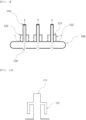
FIG. 1 is a plan view of a sparger according to an exemplary embodiment of the present invention. -
FIG. 2 is a cross-sectional view of the sparger according to an exemplary embodiment of the present invention. -
FIGS. 3a and3b are cross-sectional views of a side pipe according to an exemplary embodiment of the present invention. -
FIG. 4 is a reactor according to an exemplary embodiment of the present invention and a process flow diagram. -
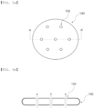
FIGS. 5a and 5b are a plan view and a cross-sectional view of a sparger according to the comparative examples. - The terms and words used in the description and claims of the present invention are not to be construed limitedly as having general or dictionary meanings but are to be construed as having meanings and concepts meeting the technical ideas of the present invention, based on a principle that the inventors are able to appropriately define the concepts of terms in order to describe their own inventions in the best mode.
- In the present invention, the term "stream" may refer to a fluid flow in the process, or may refer to the fluid itself flowing in a moving line (pipe). Specifically, the "stream" may refer to both a fluid itself flowing in a pipe connecting each device and a fluid flow. In addition, the fluid may refer to inclusion of any one or more of gas, liquid, and solid.
- In the present invention, "C#", in which "#" is a positive integer, represents all hydrocarbons having # carbon atoms. Therefore, the term "C10" represents a hydrocarbon compound having 10 carbon atoms. In addition, the term "C#+" represents all hydrocarbon molecules having # or more carbon atoms. Therefore, the term "C10+" represents a mixture of hydrocarbons having 10 or more carbon atoms.
- Hereinafter, the present invention will be described by referring to
FIGS. 1 to 4 , for better understanding of the present invention. - First, referring to
FIG.1 andFIGS. 2 which is a longitudinal sectional view based on A-A' ofFIG. 1 , thesparger 100 according to the present invention may include a main body including a plurality ofholes 130, aprotruding pipe 110 extending upward along an outer circumferential surface of the plurality of holes, and aside pipe 120 extending from a side surface of the protruding pipe. - According to an exemplary embodiment of the present invention, the
sparger 100 is, for example, provided in a lower portion of areactor 200, so that a gaseous monomer stream supplied to thereactor 200 may be dispersed upward and simultaneously, a liquid reaction medium in thereactor 200 may be mixed to improve a conversion rate of the monomer. - A main body of the
sparger 100 may be freely designed depending on the shape of thereactor 200, and for example, the main body of thesparger 100 may be formed in a disc shape having an outer circumferential surface having the same structure as the inner surface of thereactor 200. Here, the outer circumferential surface of the main body may be designed to be closely adhered to the inner surface of thereactor 200. - The main body may have a diameter of, for example, 100 mm to 1500 mm, 100 mm to 1000 mm, or 100 mm to 500 mm, and a thickness of, for example, more than 0 mm and 100 mm or less, 1 mm to 50 mm, or 10 mm to 30 mm.
- According to an exemplary embodiment of the present invention, the main body of the
sparger 100 may include ahole 130 formed by penetrating upper and lower surfaces of the main body of thesparger 100. Thehole 130 may be formed in plural at equal intervals in the center and along the circumference of the main body. Specifically, a gaseous material, for example, a monomer stream, which is supplied from the lower portion of the reactor, may be uniformly sprayed into a reaction region provided with a reaction medium inside thereactor 200, through theholes 130 formed at equal intervals in the center and along the circumference of the main body. - When the main body has a disc shape, the diameter of the
hole 130 may be 1% to 50%, 1% to 30%, or 1% to 10% of the diameter of the main body. When the diameter of thehole 130 is within the range, the shutdown of the reactor due to the fouling in the sparger may be prevented, and also the mixing efficiency in the reactor is increased to minimize a dead volume, and thus, an effect of increasing a reaction conversion rate may be obtained. - The plurality of holes may have the same diameter, and holes having a relatively large diameter and holes having a relatively small diameter may be included. When the diameters of the holes are differently formed as such, a portion which is not mixed with a gaseous material passing through a hole having a relatively large diameter may be mixed with a gaseous material passing through a hole having a small diameter, and thus, the mixing efficiency of a liquid reaction medium in the
reactor 200 may be increased. - Meanwhile, according to an exemplary embodiment of the present invention, the
sparger 100 may include aprotruding pipe 110 extending upward along the outer circumferential surface of each of the plurality ofholes 130. The outer circumferential surface may refer to the outer circumferential surface of an opening formed by thehole 130 in the upper surface of the main body of thesparger 100. Therefore, the main body of thesparger 100 and the protrudingpipe 110 may be integrally formed. Meanwhile, "upward" may refer to "toward the reaction region" provided with a reaction medium in thereactor 200. - The gaseous material, for example, a gaseous monomer stream, which is supplied from the lower portion of the
sparger 100 through thehole 130, may pass through the main body of thesparger 100 through the hole, be dispersed in the reaction region through the protrudingpipe 110, and be supplied. A flow of the gaseous material is indicated by a dotted line inFIG. 2 . - That is, referring to
FIGS. 5A and 5B regarding aconventional sparger 140, it is recognized that the upper portion of the main body of thesparger 140 and the upper surface of the opening of thehole 150 have the same or similar surface height. When the gaseous material (reactant) is supplied to the reaction region provided with the reaction medium in the upper portion of thesparger 140 through thesparger 140, the reaction product, heavy byproduct, and the like produced by the reaction have a higher density than the reaction medium and sink down, and thus, blockage of the hole 150 (fouling) easily occurs. Furthermore, as the reaction proceeds, the reaction product and the heavy by-products are deposited on the upper surface of the main body of thesparger 140, and thus, uniform mixing was impossible. - However, the
sparger 100 according to an exemplary embodiment of the present invention is provided with aprotruding pipe 110, whereby the surface height of the protrudingpipe 110 may be formed to be higher than the surface height of the upper surface of the main body of thesparger 100. Thus, a linear velocity of the gaseous monomer stream which passes through thesparger 100 and is supplied to the reactor is maintained constant, while a possibility of fouling occurrence may be lowered. Further, a wash cycle to shut down thereactor 200 and wash the inside of thereactor 200 and devices such as thesparger 100 may be extended. Furthermore, in the present invention in which the gaseous monomer is supplied to the reaction region through the protrudingpipe 110, the gaseous monomer may be supplied to a deeper reaction region to secure a larger uniform reaction region as compared with the conventional technology, and thus, the performance of the reactor, for example, the conversion rate may be improved. - For this, the relationship between a height (LP) of the protruding pipe, that is, a difference (LP) between a surface height of an upper surface of the
sparger 140 and a surface height of the protruding pipe and a thickness (LB) of the main body of thesparger 100 may satisfy the following Equation 1:
- More specifically, the height (LP) of the protruding pipe may satisfy 10LB≥LP≥LB, more specifically, 5LB≥LP≥LB. Within the range, an effect of maximizing a uniform reaction region and preventing the fouling of holes may be achieved.
- Meanwhile, according to an exemplary embodiment of the present invention, the
sparger 100 of the present invention may include aside pipe 120 extending from the side surface of the protrudingpipe 110. Theside pipe 120 may include ahorizontal pipe part 121 which horizontally extends from the side surface of the protrudingpipe 110 and adownward pipe part 122 which extends downward from the end of the horizontal pipe part. The end of thedownward pipe part 122 and the upper end of the main body may be formed to be spaced apart. - Specifically, a gaseous material (gaseous monomer) supplied from the lower portion of the main body of the
sparger 100 through a plurality ofholes 130 passes through the protrudingpipe 110 and moves upward, and in this process, a part of the gaseous material moving through the protrudingpipe 110 may be discharged through theside pipe 120. That is, a part of the gaseous material passes through thehorizontal pipe part 121 which extends in a direction parallel to the upper surface of thesparger 100, of theside pipe 120, and thedownward pipe part 122 which extends downward so as to face the upper surface of thesparger 100, of theside pipe 120, sequentially, thereby being sprayed on the upper surface of the main body of thesparger 100. - Here, the flow rate of the gaseous material discharged through the
side pipe 120 may be 5% to 150 of the flow rate of the gaseous material supplied through the holes. That is, when the flow rate of the gaseous material discharged from theside pipe 120 is 5% or more, the effect of increasing the mixing efficiency to the upper surface of the main body of thesparger 100 may be achieved, and when the flow rate is 15% or less, the gaseous material may be sufficiently transferred to the reaction region through the protrudingpipe 110 and the reaction region is secured to the maximum, thereby obtaining an effect such as an increase in a conversion rate. - As described above, since the reaction product, the heavy by-products, and the like produced by the reaction has a relatively high density, they may sink toward the
sparger 100 or be deposited on thesparger 100. The product and the heavy by-products of the reaction may be mixed by the flow of the gaseous material which is discharged and sprayed through thedownward pipe part 122, which increases the mixing efficiency to minimize a dead volume, and on the other hand, may obtain an effect of increasing a reaction conversion rate. - According to an exemplary embodiment of the present invention, the end of the
downward pipe part 122 may include an inclined part so that the surface height of a portion adjacent to the protrudingpipe 110 is high. That is, referring toFIGS. 3a and3b , the surface height of the end of thedownward pipe part 122 may be formed to be the same as shown inFIG. 3a , or the surface height of the end of thedownward pipe part 122 is formed so that the surface height of the portion adjacent to the protrudingpipe 110 is high as shown inFIG. 3b , and thus, the inclined part may be entirely introduced. When the inclined part is introduced to the end of thedownward pipe part 122, the spraying strength of the gaseous material discharged through thedownward pipe part 122 may be increased, thereby increasing the mixing efficiency for the upper surface of the main body of thesparger 100. - According to an exemplary embodiment of the present invention, an angle between the
horizontal pipe part 121 and thedownward pipe part 122 may be 75° to 135°. As described above, thesparger 100 may include a plurality ofholes 130 formed along the circumference in the center of the main body. For example, in the case ofhole 130 of which the position is adjacent to the circumference of the main body of thesparger 100, that is, thehole 130 adjacent to the side wall of the reactor, the angle between thehorizontal pipe part 121 and thedownward pipe part 122 may be formed to be larger than 90°. Thus, the gaseous material is sprayed and dispersed more directly on/in the reaction product, the heavy by-products, and the like deposited on a part where the reactor side wall and thesparger 100 are connected, thereby further improving the mixing efficiency. - Likewise, the number of
side pipes 120 extending from one protrudingpipe 110 may be 2 to 4. For example, when a spacing betweenholes 130 of thesparger 100 is narrow, the number of theside pipe 120 extending from the one protrudingpipe 110 may be 2, and when a spacing betweenholes 130 is large, the number may be 4, thereby improving the mixing efficiency depending on the spraying of the gaseous material. - Meanwhile, according to the present invention, a
reactor 200 comprising thesparger 100 is provided. Specifically, as shown inFIG. 4 , thereactor 200 may include amonomer supply line 210 through which a gaseous monomer stream is supplied; and thesparger 100 according to the present invention for dispersing the gaseous monomer stream supplied through themonomer supply line 210. - According to an exemplary embodiment of the present invention, the
reactor 200 may be a reactor appropriate for a continuous process. For example, thereactor 200 may include any one or more reactors selected from the group consisting of a continuous stirred-tank reactor, a plug flow reactor, and a bubble column reactor. As a specific example, thereactor 200 may be a bubble column reactor. Thus, the monomer may be continuously reacted. - According to an exemplary embodiment of the present invention, the
reactor 200 may be for producing an oligomer by oligomerizing a monomer in the presence of a catalyst and a solvent. - That is, referring to
FIG. 4 , a catalyst, a cocatalyst, and a solvent may be supplied from the side portion of thereactor 200 to the reaction region in the reactor through eachsupply line 220. The catalyst, the cocatalyst, and the solvent may be supplied to eachseparate supply line 220 as shown inFIG. 4 , and the catalyst may be mixed with the solvent, the cocatalyst may be mixed with the solvent, and supplied through two supply lines. - The monomer may include ethylene. Specifically, a gaseous monomer stream including an ethylene monomer is introduced into the
reactor 200 through amonomer supply line 210 provided in a lower portion of thereactor 200, and the gaseous monomer stream is dispersed by thesparger 100 and oligomerized in a reaction medium in thereactor 200, thereby producing an α-olefin product to be desired. - According to an exemplary embodiment of the present invention, a spraying part extending from the monomer supply line and provided may be further included. A gaseous ethylene monomer transferred through the
monomer supply line 210 may be sprayed through the spray part and pass through thesparger 100. - The spray part may be formed to be extended from the
monomer supply line 210 and branched into multiple pipes, and a spray nozzle may be formed at each end of the branched multiple pipes. Specifically, the gaseous ethylene monomer transferred through themonomer supply line 210 may be introduced to thereactor 200 through the spray nozzle of the spray part. As such, the gaseous ethylene monomer introduced to thereactor 200 may pass through thesparger 100 and be sprayed in the upper direction of thereactor 200. As such, since the spray part is provided, an additional apparatus such as a conventional deflector is not needed, and a difficulty in maintaining a constant linear velocity of the gaseous monomer stream when the conventional deflector is used may be solved. As such, the linear velocity of the gaseous monomer stream is maintained constant, whereby a dispersion degree of a reaction solution and the by-products in the reactor may be maintained uniform and accumulation of the by-products on one side may be prevented. - The oligomerization reaction is carried out in a lower or a middle of the reaction region of the
reactor 200, and the oligomerization reaction of the monomer may be carried out in a liquid state being dissolved in a solvent in the presence of a catalyst and a cocatalyst. - The oligomerization reaction may refer to a reaction in which a monomer is oligomerized. The oligomerization may be referred to as trimerization or tetramerization depending on the number of monomers to be polymerized, and these are collectively called multimerization.
- In the oligomerization reaction of the monomer, an unreacted monomer and a vaporized solvent in the
reactor 200 may be discharged to the upper portion of thereactor 200, which may be circulated to thereactor 200 and reused in the oligomerization reaction of the monomer. In addition, the oligomer produced by the oligomerization reaction of the monomer may be obtained by separation through the lower side of thereactor 200. - The α-olefin, which is an important material used in copolymers, cleaning agents, lubricants, plasticizers, and the like, is commercially widely used, and in particular, 1-hexene and 1-octene are often used as a comonomer for adjusting the density of polyethylene in the preparation of linear low-density polyethylene (LLDPE). The α-olefin such as 1-hexene and 1-octene may be produced by, for example, a trimerization reaction or tetramerization reaction of an ethylene monomer.
- The oligomerization reaction of the monomer may be carried out by a homogeneous liquid phase reaction, a slurry reaction in which the catalyst is in the form of being partially not dissolved or completely not dissolved, a two-phase liquid/liquid reaction, or a bulk phase reaction or gas phase reaction of which the product acts as a main medium, in the presence or absence of a solvent, by applying the reaction system and a common contact technology.
- The solvent, the catalyst, and the cocatalyst may be supplied in a liquid phase to the lower side of the
reactor 200. - The catalyst may include a transition metal source. The transition metal source may be, for example, a compound including one or more selected from the group consisting of chromium (III) acetylacetonate, chromium (III) chloride tetrahydrofuran, chromium (III) 2-ethylhexanoate, chromium (III) tris(2,2,6,6-tetramethyl-3,5-heptanedionate), chromium (III) benzoylacetonate, chromium (III) hexafluoro-2,4-pentanedionate, chromium (III) acetate hydroxide, chromium (III) acetate, chromium (III) butyrate, chromium (III) pentanoate, chromium (III) laurate, and chromium (III) stearate.
- The cocatalyst may include, for example, one or more selected from the group consisting of trimethyl aluminum, triethyl aluminum, triisopropyl aluminum, triisobutyl aluminum, ethylaluminum sesquichloride, diethylaluminum chloride, ethyl aluminum dichloride, methylaluminoxane, modified methylaluminoxane, and borate.
- The solvent used in the oligomerization reaction of a monomer may include one or more selected from the group consisting of n-pentane, n-hexane, n-heptane, cyclohexane, methylcyclohexane, octane, cyclooctane, decane, dodecane, benzene, xylene, 1,3,5-trimethylbenzene, toluene, ethylbenzene, chlorobenzene, dichlorobenzene, and trichlorobenzene.
- As such, in the process of oligomerizing a monomer in the presence of the catalyst and the solvent, adhesive by-products such as polymers are produced in addition to an oligomer product. The by-products may block holes formed in the
sparger 100 to cause fouling. - Regarding this, the
reactor 200 according to the present invention uses thesparger 100 according to the present invention described above, thereby preventing blockage of the holes in thesparger 100 due to the fouling to extend the wash cycle of thereactor 200, and thus, preventing a production decrease due to a decreased operation time and reducing costs required in the wash process. - According to an exemplary embodiment of the present invention, in the
reactor 200, an apparatus required for oligomer production such as a valve, a condenser, a reboiler, a pump, a cooling facility, a filter, an agitator, a compressor, and a mixer may be further installed, if necessary. - Hereinabove, the sparger according to the present invention and the reactor comprising the same have been described and illustrated in the drawings; however, the description and the illustration in the drawings are the description and the illustration of only core constitutions for understanding of the present invention, and in addition to the process and apparatus described above and illustrated in the drawings, the process and the apparatus which are not described and illustrated separately may be appropriately applied and used for using the sparger according to the present invention and the reactor comprising the same.
- Hereinafter, the present invention will be described in more detail by the examples. However, the following examples are provided for illustrating the present invention, and it is apparent to a person skilled in the art that various modifications and alterations may be made without departing from the scope and spirit of the present invention and the scope of the present invention is not limited thereto.
- A
sparger 100 according toFIG. 1 according to the present invention was provided in abubble column reactor 200, as shown inFIG. 4 , and the oligomerization reaction of an ethylene monomer was performed. Specifically, a solvent, a catalyst, and a cocatalyst were supplied to a lower side of thereactor 200, a gaseous ethylene monomer stream was supplied through amonomer supply line 210 provided in a lower portion of thereactor 200, and thesparger 100 was used to disperse the stream upward to perform an oligomerization reaction in a liquid reaction medium in thereactor 200. An α-olefin produced by the oligomerization reaction was separated in the lower side of thereactor 200 and obtained, and an unreacted monomer and a vaporized solvent were discharged to an upper portion of thereactor 200. - At this time, the diameter of the main body of the
sparger 100 was formed to be 300 mm, the thickness of the main body of thesparger 100 was formed to be 20 mm, the height of the protrudingpipe 110 was formed to be 60 mm, and aside pipe 120 was provided in the side surface of the protrudingpipe 110. - In this case, it was confirmed that a part of the gaseous ethylene monomer stream passed through the protruding
pipe 110 of thesparger 100 and was supplied to a reaction region, and the remaining ethylene monomer stream passed through a side pipe and was sprayed on the upper surface of the main body of thesparger 100. - As a result of Example 1, the mixing efficiency of the ethylene monomer was increased to increase the production amount of the α-olefin. In addition, fouling occurrence in the
sparger 100 was decreased to extend a shutdown cycle for washing thereactor 200. - The process was performed in the same manner as in Example 1, except that a
sparger 140 which did not have the protruding pipe and the side pipe, so that the surface height of thehole 150 and the surface height of the main body of thesparger 140 were the same, as shown inFIGS. 5A and 5B , was used as thesparger 140, - In this case, it was confirmed that the mixing efficiency of the ethylene monomer was decreased as compared with Example 1 so that the production amount of α-olefin was decreased, and a fouling occurrence rate in the
sparger 140 was increased to shorten the shutdown cycle for washing thereactor 200.
Claims (10)
- A sparger comprising:a main body including a plurality of holes;a protruding pipe extending upward along an outer circumferential surface of the plurality of holes; anda side pipe extending from a side surface of the protruding pipe.
- The sparger of claim 1, wherein the side pipe includes a horizontal pipe part which horizontally extends from the side surface of the protruding pipe and a downward pipe part which extends downward from an end of the horizontal pipe part.
- The sparger of claim 2, wherein the end of the downward pipe part and an upper end of the main body are spaced apart.
- The sparger of claim 2, wherein the end of the downward pipe part includes an inclined part so that a surface height of a portion adjacent to the protruding pipe is high.
- The sparger of claim 2, wherein an angle between the horizontal pipe part and the downward pipe part is 75° to 135°.
- The sparger of claim 1, wherein a gaseous material supplied from a lower portion of the main body through the plurality of holes passes through the protruding pipe and moves upward, and a part of the gaseous material moving through the protruding pipe is discharged through the side pipe.
- The sparger of claim 6, wherein a flow rate of the gaseous material discharged through the side pipe is 5% to 150 of a flow rate of the gaseous material supplied through the holes.
- The sparger of claim 1, wherein the sparger satisfies the following Equation 1:

- The sparger of claim 1, wherein the number of the side pipes extending from one protruding pipe is 2 to 4.
- A reactor comprising:a monomer supply line through which a gaseous monomer stream is supplied; andthe sparger of claim 1 for dispersing the gaseous monomer stream supplied through the monomer supply line.
Applications Claiming Priority (2)
| Application Number | Priority Date | Filing Date | Title |
|---|---|---|---|
| KR1020210159855A KR102800056B1 (en) | 2021-11-18 | 2021-11-18 | Sparger and reactor comprising the same |
| PCT/KR2022/009532 WO2023090564A1 (en) | 2021-11-18 | 2022-07-01 | Sparger and reactor comprising same |
Publications (2)
| Publication Number | Publication Date |
|---|---|
| EP4212238A1 true EP4212238A1 (en) | 2023-07-19 |
| EP4212238A4 EP4212238A4 (en) | 2023-09-27 |
Family
ID=86397231
Family Applications (1)
| Application Number | Title | Priority Date | Filing Date |
|---|---|---|---|
| EP22862402.9A Pending EP4212238A4 (en) | 2021-11-18 | 2022-07-01 | SPRINKLER AND REACTOR WITH IT |
Country Status (6)
| Country | Link |
|---|---|
| US (1) | US20240286099A1 (en) |
| EP (1) | EP4212238A4 (en) |
| JP (1) | JP7575169B2 (en) |
| KR (1) | KR102800056B1 (en) |
| CN (1) | CN116472106B (en) |
| WO (1) | WO2023090564A1 (en) |
Family Cites Families (38)
| Publication number | Priority date | Publication date | Assignee | Title |
|---|---|---|---|---|
| US2191919A (en) * | 1936-01-21 | 1940-02-27 | Sinclair Refining Co | Art of refining |
| US3133128A (en) * | 1960-09-12 | 1964-05-12 | Universal Oil Prod Co | Contacting of fluids |
| US3197387A (en) * | 1963-05-20 | 1965-07-27 | Baldwin Lima Hamilton Corp | Multi-stage flash evaporators |
| US3398718A (en) * | 1965-03-10 | 1968-08-27 | Atomic Energy Commission Usa | Fluidized-bed coating apparatus |
| GB1214799A (en) * | 1968-07-29 | 1970-12-02 | Hitachi Ltd | Flash evaporator |
| GB1292808A (en) * | 1969-01-17 | 1972-10-11 | Laporte Industries Ltd | Improvements in and relating to fluidised bed reactors |
| JP2608805B2 (en) * | 1990-11-02 | 1997-05-14 | 宇部興産株式会社 | Gas dispersion tube of fluidized bed equipment |
| CN1134527C (en) * | 1994-04-29 | 2004-01-14 | 切夫里昂美国公司 | Catalyst, method and apparatus for continuous particle displacement system |
| US6932889B1 (en) * | 1996-06-27 | 2005-08-23 | Robert R. Holcomb | Water treatment device and method |
| EP0832877B1 (en) * | 1996-09-25 | 2001-11-21 | Mitsubishi Rayon Co., Ltd. | Ammoxidation method in fluidized-bed reactor |
| DE10147674A1 (en) * | 2001-09-27 | 2003-04-24 | Gea Wiegand Gmbh | Device for the evaporation of a liquid substance and subsequent condensation of the resulting vapor |
| DE10232789A1 (en) * | 2002-07-18 | 2004-02-05 | Vinnolit Technologie Gmbh & Co.Kg Werk Gendorf | Device for introducing gas into a fluid bed and method therefor |
| CN1233454C (en) * | 2003-09-28 | 2005-12-28 | 上海兖矿能源科技研发有限公司 | Gas distributor in use for reactor in slurry state bed in three phases |
| CN101130551B (en) * | 2007-09-05 | 2010-10-13 | 青岛科技大学 | Heat conduction oil distributor of organosilicon monomer fluidized bed reactor and manufacturing method thereof |
| KR100954351B1 (en) * | 2007-10-10 | 2010-04-21 | 세메스 주식회사 | Carbon nanotube manufacturing apparatus and method |
| EP2482008B1 (en) * | 2008-01-11 | 2014-10-08 | Johnson Controls Technology Company | Evaporator |
| CN201605166U (en) * | 2009-11-27 | 2010-10-13 | 上海森和投资有限公司 | Hydrogenation silicon tetrachloride boiling bed reactor |
| EP2415527B1 (en) * | 2010-08-04 | 2013-11-06 | Siemens Aktiengesellschaft | Aeration device for a flotation cell, flotation cell and flotation method |
| US9683784B2 (en) * | 2012-01-27 | 2017-06-20 | Carrier Corporation | Evaporator and liquid distributor |
| KR101544637B1 (en) * | 2013-02-26 | 2015-08-17 | 주식회사 엘지화학 | Gas diffusing column for fluidized bed reactor and fluidized bed reactor with same |
| KR101587684B1 (en) * | 2013-03-07 | 2016-01-21 | 주식회사 엘지화학 | Distributor for fluidized bed reactor and fluidized bed reactor with same |
| KR101651315B1 (en) * | 2013-04-17 | 2016-08-25 | 주식회사 엘지화학 | Fluidized bed reactor and preparatio of carbon nanostructures using same |
| CN203379868U (en) * | 2013-07-16 | 2014-01-08 | 中石化洛阳工程有限公司 | Gas distributor for slurry bed reactor |
| RU2566504C1 (en) * | 2014-08-08 | 2015-10-27 | Общество с ограниченной ответственностью "Научно-производственное объединение ЕВРОХИМ" | Method for alkylaromatic hydrocarbon oxidation and reaction for implementing it |
| MX363834B (en) * | 2014-12-30 | 2019-04-04 | Exxonmobil Upstream Res Co | Accumulation and melt tray assembly for a distillation tower. |
| CN106512869A (en) * | 2016-11-22 | 2017-03-22 | 中国科学院上海高等研究院 | Fluid uniform distribution device with fractal structure |
| CN206853645U (en) * | 2017-06-26 | 2018-01-09 | 辽宁加宝石化设备有限公司 | A kind of low pressure drop high stability distributor and reactor |
| CN108031410A (en) * | 2017-12-26 | 2018-05-15 | 北京华福工程有限公司 | A kind of gas feed distributor and paste state bed reactor |
| KR102637591B1 (en) | 2018-03-21 | 2024-02-19 | 주식회사 엘지화학 | Alpha olefin synthesis method and apparatus thereof |
| KR20190132118A (en) * | 2018-05-18 | 2019-11-27 | 재단법인 포항산업과학연구원 | Distributor and manufacturing apparatus of titanium tetrachloride |
| CN109092216A (en) * | 2018-08-21 | 2018-12-28 | 攀钢集团攀枝花钢铁研究院有限公司 | Low-temperature boiling chlorination furnace reaction segment structure |
| KR102100463B1 (en) * | 2019-07-17 | 2020-04-13 | 대영이엔지 주식회사 | Air Diffuser Improved Purifying Efficiency |
| KR102851288B1 (en) * | 2019-12-27 | 2025-08-28 | 에스케이이노베이션 주식회사 | Fludized bed reactor and method of recycling active metal of lithium secondary battery utilizing the same |
| CN113181841A (en) * | 2020-01-14 | 2021-07-30 | 万华化学集团股份有限公司 | A gas-liquid-solid three-phase fixed bubbling bed reactor and organic wastewater treatment method |
| US11896970B2 (en) * | 2020-02-12 | 2024-02-13 | Hindustan Petroleum Corporation Limited | Gas and liquid distributor for bubble column reactor |
| EP4103317A4 (en) * | 2020-02-12 | 2023-09-06 | Hindustan Petroleum Corporation Ltd. | Gas distributor for bubble column reactor |
| KR102751373B1 (en) * | 2020-02-18 | 2025-01-06 | 에스케이이노베이션 주식회사 | Method of recycling active metal of lithium secondary battery utilizing the same |
| MX2022014946A (en) * | 2020-05-28 | 2023-01-04 | Solugen Inc | REACTOR BUBBLER ASSEMBLY. |
-
2021
- 2021-11-18 KR KR1020210159855A patent/KR102800056B1/en active Active
-
2022
- 2022-07-01 JP JP2023514817A patent/JP7575169B2/en active Active
- 2022-07-01 EP EP22862402.9A patent/EP4212238A4/en active Pending
- 2022-07-01 WO PCT/KR2022/009532 patent/WO2023090564A1/en not_active Ceased
- 2022-07-01 CN CN202280005648.0A patent/CN116472106B/en active Active
- 2022-07-01 US US18/026,032 patent/US20240286099A1/en active Pending
Also Published As
| Publication number | Publication date |
|---|---|
| KR102800056B1 (en) | 2025-04-23 |
| CN116472106B (en) | 2026-04-14 |
| KR20230073044A (en) | 2023-05-25 |
| EP4212238A4 (en) | 2023-09-27 |
| US20240286099A1 (en) | 2024-08-29 |
| CN116472106A (en) | 2023-07-21 |
| WO2023090564A1 (en) | 2023-05-25 |
| JP2023554571A (en) | 2023-12-28 |
| JP7575169B2 (en) | 2024-10-29 |
Similar Documents
| Publication | Publication Date | Title |
|---|---|---|
| US11583825B2 (en) | Apparatus for preparing oligomer | |
| US11511255B2 (en) | Apparatus for preparing oligomer | |
| US11938457B2 (en) | Apparatus for preparing oligomer | |
| EP4032608B1 (en) | Sparger and reactor comprising same | |
| EP4212238A1 (en) | Sparger and reactor comprising same | |
| EP4209262A1 (en) | Bubble column reactor | |
| KR102849255B1 (en) | Bubble column reactor | |
| EP4218997A1 (en) | Bubble column reactor | |
| KR102728114B1 (en) | Apparatus for preparing oligomer |
Legal Events
| Date | Code | Title | Description |
|---|---|---|---|
| STAA | Information on the status of an ep patent application or granted ep patent |
Free format text: STATUS: UNKNOWN |
|
| STAA | Information on the status of an ep patent application or granted ep patent |
Free format text: STATUS: THE INTERNATIONAL PUBLICATION HAS BEEN MADE |
|
| PUAI | Public reference made under article 153(3) epc to a published international application that has entered the european phase |
Free format text: ORIGINAL CODE: 0009012 |
|
| STAA | Information on the status of an ep patent application or granted ep patent |
Free format text: STATUS: REQUEST FOR EXAMINATION WAS MADE |
|
| 17P | Request for examination filed |
Effective date: 20230310 |
|
| AK | Designated contracting states |
Kind code of ref document: A1 Designated state(s): AL AT BE BG CH CY CZ DE DK EE ES FI FR GB GR HR HU IE IS IT LI LT LU LV MC MK MT NL NO PL PT RO RS SE SI SK SM TR |
|
| A4 | Supplementary search report drawn up and despatched |
Effective date: 20230825 |
|
| RIC1 | Information provided on ipc code assigned before grant |
Ipc: B01J 8/44 20060101AFI20230821BHEP |
|
| DAV | Request for validation of the european patent (deleted) | ||
| DAX | Request for extension of the european patent (deleted) |