EP4212237A1 - Reactor - Google Patents
Reactor Download PDFInfo
- Publication number
- EP4212237A1 EP4212237A1 EP21867090.9A EP21867090A EP4212237A1 EP 4212237 A1 EP4212237 A1 EP 4212237A1 EP 21867090 A EP21867090 A EP 21867090A EP 4212237 A1 EP4212237 A1 EP 4212237A1
- Authority
- EP
- European Patent Office
- Prior art keywords
- refrigerant
- reactor
- jacket
- inlet
- refrigerant jacket
- Prior art date
- Legal status (The legal status is an assumption and is not a legal conclusion. Google has not performed a legal analysis and makes no representation as to the accuracy of the status listed.)
- Pending
Links
Images


Classifications
-
- B—PERFORMING OPERATIONS; TRANSPORTING
- B01—PHYSICAL OR CHEMICAL PROCESSES OR APPARATUS IN GENERAL
- B01J—CHEMICAL OR PHYSICAL PROCESSES, e.g. CATALYSIS OR COLLOID CHEMISTRY; THEIR RELEVANT APPARATUS
- B01J19/00—Chemical, physical or physico-chemical processes in general; Their relevant apparatus
- B01J19/18—Stationary reactors having moving elements inside
-
- B—PERFORMING OPERATIONS; TRANSPORTING
- B01—PHYSICAL OR CHEMICAL PROCESSES OR APPARATUS IN GENERAL
- B01J—CHEMICAL OR PHYSICAL PROCESSES, e.g. CATALYSIS OR COLLOID CHEMISTRY; THEIR RELEVANT APPARATUS
- B01J2219/00—Chemical, physical or physico-chemical processes in general; Their relevant apparatus
- B01J2219/00049—Controlling or regulating processes
- B01J2219/00051—Controlling the temperature
- B01J2219/00074—Controlling the temperature by indirect heating or cooling employing heat exchange fluids
- B01J2219/00076—Controlling the temperature by indirect heating or cooling employing heat exchange fluids with heat exchange elements inside the reactor
- B01J2219/00083—Coils
-
- B—PERFORMING OPERATIONS; TRANSPORTING
- B01—PHYSICAL OR CHEMICAL PROCESSES OR APPARATUS IN GENERAL
- B01J—CHEMICAL OR PHYSICAL PROCESSES, e.g. CATALYSIS OR COLLOID CHEMISTRY; THEIR RELEVANT APPARATUS
- B01J2219/00—Chemical, physical or physico-chemical processes in general; Their relevant apparatus
- B01J2219/00049—Controlling or regulating processes
- B01J2219/00051—Controlling the temperature
- B01J2219/00074—Controlling the temperature by indirect heating or cooling employing heat exchange fluids
- B01J2219/00076—Controlling the temperature by indirect heating or cooling employing heat exchange fluids with heat exchange elements inside the reactor
- B01J2219/00085—Plates; Jackets; Cylinders
-
- B—PERFORMING OPERATIONS; TRANSPORTING
- B01—PHYSICAL OR CHEMICAL PROCESSES OR APPARATUS IN GENERAL
- B01J—CHEMICAL OR PHYSICAL PROCESSES, e.g. CATALYSIS OR COLLOID CHEMISTRY; THEIR RELEVANT APPARATUS
- B01J2219/00—Chemical, physical or physico-chemical processes in general; Their relevant apparatus
- B01J2219/00049—Controlling or regulating processes
- B01J2219/00051—Controlling the temperature
- B01J2219/00074—Controlling the temperature by indirect heating or cooling employing heat exchange fluids
- B01J2219/00087—Controlling the temperature by indirect heating or cooling employing heat exchange fluids with heat exchange elements outside the reactor
- B01J2219/0009—Coils
-
- B—PERFORMING OPERATIONS; TRANSPORTING
- B01—PHYSICAL OR CHEMICAL PROCESSES OR APPARATUS IN GENERAL
- B01J—CHEMICAL OR PHYSICAL PROCESSES, e.g. CATALYSIS OR COLLOID CHEMISTRY; THEIR RELEVANT APPARATUS
- B01J2219/00—Chemical, physical or physico-chemical processes in general; Their relevant apparatus
- B01J2219/00049—Controlling or regulating processes
- B01J2219/00051—Controlling the temperature
- B01J2219/00074—Controlling the temperature by indirect heating or cooling employing heat exchange fluids
- B01J2219/00087—Controlling the temperature by indirect heating or cooling employing heat exchange fluids with heat exchange elements outside the reactor
- B01J2219/00094—Jackets
-
- B—PERFORMING OPERATIONS; TRANSPORTING
- B01—PHYSICAL OR CHEMICAL PROCESSES OR APPARATUS IN GENERAL
- B01J—CHEMICAL OR PHYSICAL PROCESSES, e.g. CATALYSIS OR COLLOID CHEMISTRY; THEIR RELEVANT APPARATUS
- B01J2219/00—Chemical, physical or physico-chemical processes in general; Their relevant apparatus
- B01J2219/00761—Details of the reactor
- B01J2219/00763—Baffles
- B01J2219/00765—Baffles attached to the reactor wall
- B01J2219/00768—Baffles attached to the reactor wall vertical
-
- B—PERFORMING OPERATIONS; TRANSPORTING
- B01—PHYSICAL OR CHEMICAL PROCESSES OR APPARATUS IN GENERAL
- B01J—CHEMICAL OR PHYSICAL PROCESSES, e.g. CATALYSIS OR COLLOID CHEMISTRY; THEIR RELEVANT APPARATUS
- B01J2219/00—Chemical, physical or physico-chemical processes in general; Their relevant apparatus
- B01J2219/00761—Details of the reactor
- B01J2219/00763—Baffles
- B01J2219/00765—Baffles attached to the reactor wall
- B01J2219/0077—Baffles attached to the reactor wall inclined
- B01J2219/00772—Baffles attached to the reactor wall inclined in a helix
-
- B—PERFORMING OPERATIONS; TRANSPORTING
- B01—PHYSICAL OR CHEMICAL PROCESSES OR APPARATUS IN GENERAL
- B01J—CHEMICAL OR PHYSICAL PROCESSES, e.g. CATALYSIS OR COLLOID CHEMISTRY; THEIR RELEVANT APPARATUS
- B01J2219/00—Chemical, physical or physico-chemical processes in general; Their relevant apparatus
- B01J2219/00761—Details of the reactor
- B01J2219/00763—Baffles
- B01J2219/00779—Baffles attached to the stirring means
Definitions
- the present invention relates to a reactor.
- Two or more unit materials or monomers serving as raw materials of polymers are coupled through a chemical reaction to produce compounds having high molecular weight, and this chemical reaction is referred to as polymerization.
- the polymers are called dimers, trimers, or multimers according to the degree of polymerization.
- the polymerization reaction occurs in reactors.
- the polymerization reaction may occur as monomers, solvents, and catalysts are input into the reactors.
- Polybutene is a representative example of the cationic polymerization.
- the reactor, in which the polybutene polymerization occurs needs to be maintained at a low temperature for stable polymerization. According to the related art, it is required to maintain a low temperature of -90 degrees Celsius to -60 degrees Celsius. However, in the related art, it is difficult to continuously maintain the inside of a reactor at a uniform low temperature state. Accordingly, it is difficult to obtain stable molecular weight, and it is difficult for a selective reaction of isomers to occur. [PRIOR ART DOCUMENTS] (Patent Document) Korean Patent Publication No. 10-2019-0027623
- One aspect of the present invention is to provide a reactor in which low-temperature heat transfer may be uniformly performed.
- a reactor according to an embodiment of the present invention comprises: a reactor tank having an accommodation space therein in which a polymerization reaction of a reactive fluid is performed; an outer refrigerant jacket which is positioned outside the reactor tank and through which a refrigerant flows; and an inner refrigerant jacket which is positioned inside the reactor tank and through which a refrigerant flows.
- the refrigerants of the outer refrigerant jacket and the inner refrigerant jacket may flow in opposite directions to each other.
- the refrigerant jackets, through which the refrigerants flow are provided inside the reactor in the form of an inward and outward double structure, and thus, it is possible to uniformly cool the reactants.
- the inlet and outlet paths for the refrigerants are provided on opposite sides in the jacket positioned relatively inside and the jacket positioned relatively outside, and thus, the refrigerants flow in reverse directions to each other. Accordingly, it is possible to more uniformly cool the reactants (reactive fluids).
- FIG. 1 is a perspective view exemplarily showing a reactor according to an embodiment of the present invention
- FIG. 2 is a cross-sectional view exemplarily showing a reactor according to an embodiment of the present invention
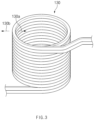
- FIG. 3 is a perspective view exemplarily showing an inner refrigerant jacket in a reactor according to an embodiment of the present invention.
- a reactor 100 according to an embodiment of the present invention comprises a reactor tank 110 having an accommodation space 111 therein, an outer refrigerant jacket 120 which is positioned outside the reactor tank 110 and through which a refrigerant flows, and an inner refrigerant jacket 130 which is positioned inside the reactor tank 110 and through which a refrigerant flows.
- the reactor 100 may further comprise an impeller 140 and a guide vane 150.
- the reactor tank 110 may have the accommodation space 111 therein in which a polymerization reaction of a reactive fluid is performed.
- the reactor tank 110 may be provided in the form of a cylindrical vessel.
- the polymerization reaction may occur.
- polybutene polymerization may occur in the accommodation space 111 of the reactor tank 110. That is, a polymer may be manufactured as the polymerization reaction occurs inside the reactor tank 110, and for example, a polybutene polymer may be manufactured.
- lewis acid such as boron trifluoride (BF 3 ) or aluminum chloride (AlCl 3 ) may be used as the catalyst.
- the outer refrigerant jacket 120 is positioned outside the reactor tank 110, and the refrigerant may flow therethrough.
- the outer refrigerant jacket 120 may comprise an outer refrigerant inlet 121 through which the refrigerant flows in the outer refrigerant jacket 120 and an outer refrigerant outlet 122 through which the refrigerant is discharged.
- the outer refrigerant jacket 120 may be formed in a pipe shape in which the refrigerant flows.
- the outer refrigerant jacket 120 may be wound in a coil shape. Accordingly, the outer refrigerant jacket 120 may surround the outer surface of the reactor tank 110.
- the outer refrigerant jacket 120 may have a cross-section of a quadrangular pipe. That is, the cross-section may have a pipe having " ⁇ " shape. Accordingly, the refrigerant flowing in the outer refrigerant jacket 120 may be given directionality.
- the inner refrigerant jacket 130 is positioned inside the reactor tank 110, and the refrigerant may flow therethrough.
- the inner refrigerant jacket 130 may comprise an inner refrigerant inlet 131 through which the refrigerant flows in the inner refrigerant jacket 130 and an inner refrigerant outlet 132 through which the refrigerant is discharged.
- the inner refrigerant jacket 130 may be formed in a pipe shape in which the refrigerant flows.
- the inner refrigerant jacket 130 may have a cross-section of a quadrangular pipe. That is, the cross-section may have a pipe having " ⁇ " shape. Accordingly, the refrigerant flowing in the inner refrigerant jacket 130 may be given directionality.
- the inner refrigerant jacket 130 may be wound in a coil shape.
- the inner refrigerant jacket 130 may have a partition wall so that flow paths are formed on the inside 130a and outside 130b of the inner refrigerant jacket 130.
- the directionality of the reactive fluid is induced, and it is possible to secure a reaction time in a limited space.
- the refrigerants of the outer refrigerant jacket 120 and the inner refrigerant jacket 130 may flow in opposite directions to each other.
- outer refrigerant inlet 121 and the inner refrigerant inlet 131 may be positioned on opposite sides to each other in an up-down direction D1
- outer refrigerant outlet 122 and the inner refrigerant outlet 132 may be positioned on opposite sides to each other in the up-down direction D1.
- outer refrigerant inlet 121 and the inner refrigerant outlet 132 may be positioned on one lower side of the reactor tank 110, and the outer refrigerant outlet 122 and the inner refrigerant inlet 131 may be positioned on the other upper side of the reactor tank 110.
- inlet portions and outlet portions of the refrigerants in the outer refrigerant jacket 120 and the inner refrigerant jacket 130 are positioned on the opposite sides to each other, and thus, the refrigerants flow in reverse directions to each other. Therefore, uniform heat transfer is achieved inside the reactor tank 110, and the reactive fluid may be uniformly maintained at a low temperature.
- the reactive fluid may be maintained at an extremely low temperature through the outer refrigerant jacket 120 and the inner refrigerant jacket 130.
- a catalyst is input to the reactor 100 of the present invention so as to make a reaction of the reactive fluid while maintaining the reactor tank 110 at a temperature of -30°C to -49°C. Even if the catalyst having a temperature similar to this temperature or lower by -10°C to -20°C is supplied, heat may be appropriately transferred, and the reaction may smoothly occur.
- efficiency of heat transfer deteriorates.
- the reactor 100 of the present invention may efficiently transfer heat to the reactive fluid through the outer refrigerant jacket 120 and the inner refrigerant jacket 130, and thus, a reaction temperature may be secured even if a refrigerant having a higher temperature is supplied to the reactor 100. Accordingly, the energy efficiency is significantly improved.
- the reactive fluid may be uniformly maintained in a low temperature state, and thus, stable polymerization may be continuously made.
- stable molecular weight may be obtained, and cationic polymerization of isomers is possible.
- the impeller 140 is installed to an inner portion of the reactor tank 110 and may induce directionality of the reactive fluid.
- the impeller 140 is positioned on the inside 130a and outside 130b of the inner refrigerant jacket 130, and may induce ascent of the reactive fluid on the inside 130a of the inner refrigerant jacket 130 and descent of the reactive fluid on the outside 130b of the inner refrigerant jacket 130.
- the impeller 140 may comprise a rotary shaft 141 rotatably mounted to the reactor tank 110 and impeller blades 142 and 143 mounted to the rotary shaft 141.
- the impeller blade 142 positioned on the inside 130a of the inner refrigerant jacket 130 and the impeller blade 143 positioned on the outside 130b are provided so as to make fluids flow in opposite directions to each other.
- the impeller blade 142 positioned on the inside 130a of the inner refrigerant jacket 130 and the impeller blade 143 positioned on the outside 130b are mounted to the rotary shaft 141 while having opposite inclinations to each other.
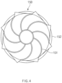
- FIG. 4 is a plan view exemplarily showing a guide vane in a reactor according to an embodiment of the present invention.
- a guide vane 150 may guide a flow of the reactive fluid in the same direction as a flow direction of the reactive fluid by the impeller 140 inside the reactor tank 110.
- the guide vane 150 comprises a support plate 152 provided in each of an upper portion and a lower portion inside the reactor tank 110 and a guide part 151 protruding from the support plate 152 toward the inside of the reactor tank 110.
- the support plates 152 may be fixed to the ceiling surface and the bottom surface of the reactor tank 110.
- the guide part 151 may spirally protrude from the support plate 152.
- the guide vane 150 may guide the flow of the reactive fluid. That is, the guide vane 150 may guide the reactive fluid that flows in the accommodation space 111 of the reactor tank 110 by the impeller 140 so that the reactive fluid easily circulates through the inside 130a and the outside 130b of the inner refrigerant jacket 130.
- the guide part 151 positioned on an upper side within the reactor tank 110 may guide the fluid, which ascends on the inside 130a of the inner refrigerant jacket 130, to move to the outside 130b of the inner refrigerant jacket 130
- the guide part 151 positioned on a lower side within the reactor tank 110 may guide the fluid, which descends on the outside 130b of the inner refrigerant jacket 130, to move to the inside 130a of the inner refrigerant jacket 130.
- the reactor 100 may further comprise a monomer/solvent inlet 160 through which a monomer and a solvent are input into the reactor tank 110, a catalyst inlet 170 through which a catalyst is input into the reactor tank 110, and a reactant outlet 180 through which a reactant is discharged.
- the monomer/solvent inlet 160 and the catalyst inlet 170 may be provided on the sides on which the outer refrigerant inlet 121 and the inner refrigerant inlet 131 are positioned. Accordingly, it may be advantageous in terms of securing a low temperature of the reactive fluid.
- the monomer/solvent inlet 160 may be provided on the side on which the inner refrigerant inlet 131 is positioned, and the catalyst inlet 170 may be provided on the side on which the outer refrigerant inlet 121 is positioned.
- the catalyst inlet 170 may be provided on one lower side of the reactor tank 110, and the monomer/solvent inlet 160 may be provided on the other upper side of the reactor tank 110.
- a reactor was manufactured, which has a vessel shape with refrigerant jackets on the outer side and the inside and is provided with an impeller therein.
- refrigerants in the refrigerant jackets on the outer side and the inside were made to flow in reverse directions to each other.
- a catalyst solution, monomer (isobutylene), and a solvent (hexane&DCM) were put into the reactor and reacted at -40 degrees for 30 minutes.
- the monomer with a concentration of 40 wt% was put into the reactor.
- Comparative Example 2 shows a yield of 62% of the molecular weight (Mw) 248 k unnecessary for the production of a product. It can be seen that while differences in temperatures between the upper and lower portions of the reactor in Comparative Example 1 and Comparative Example 2 are 7.9°C to 15.9°C, differences in temperatures between the upper and lower portions of the reactor in Preparation Example 1 and Preparation Example 2 are as significantly low as 5.1°C to 6.8°C. Thus, it can be seen that Preparation Example 1 and Preparation Example 2 may perform significantly more uniform heat transfer than Comparative Example 1 and Comparative Example 2.
- the reactors in Comparative Example 1 and Comparative Example 2 have refrigerant jackets only on the outer sides thereof and thus exhibit low heat transfer efficiency. Accordingly, it is impossible to make a design for increasing the concentration of the monomer, and there is a limit in improving productivity per unit time.
- the reactors in Preparation Example 1 and Preparation Example 2 have refrigerant jackets not only on the outer side but also the inside.
- the heat transfer areas are increased to exhibit high heat transfer efficiency, and enhancement of flowability of fluid is promoted to increase a heat transfer rate per unit time. That is, it can be seen that the directionality of the reactive fluid is induced, and it is possible to secure a reaction time in a limited space. Through this, it is possible to make a design for increasing the concentration of monomer while achieving sufficient capacity of the cooler (reactor). Thus, there are effects of making it possible to significantly increase productivity per unit time and secure material properties.
Landscapes
- Chemical & Material Sciences (AREA)
- Organic Chemistry (AREA)
- Chemical Kinetics & Catalysis (AREA)
- Polymerisation Methods In General (AREA)
- Physical Or Chemical Processes And Apparatus (AREA)
Abstract
Description
- The present application claims the benefit of the priority of
Korean Patent Application No. 10-2020-0117211, filed on September 11, 2020 Korean Patent Application No. 10-2021-0118408, filed on September 06, 2021 - The present invention relates to a reactor.
- Two or more unit materials or monomers serving as raw materials of polymers are coupled through a chemical reaction to produce compounds having high molecular weight, and this chemical reaction is referred to as polymerization. The polymers are called dimers, trimers, or multimers according to the degree of polymerization.
- The polymerization reaction occurs in reactors. The polymerization reaction may occur as monomers, solvents, and catalysts are input into the reactors. Polybutene is a representative example of the cationic polymerization. The reactor, in which the polybutene polymerization occurs, needs to be maintained at a low temperature for stable polymerization. According to the related art, it is required to maintain a low temperature of -90 degrees Celsius to -60 degrees Celsius. However, in the related art, it is difficult to continuously maintain the inside of a reactor at a uniform low temperature state. Accordingly, it is difficult to obtain stable molecular weight, and it is difficult for a selective reaction of isomers to occur.
[PRIOR ART DOCUMENTS] (Patent Document)Korean Patent Publication No. 10-2019-0027623 - One aspect of the present invention is to provide a reactor in which low-temperature heat transfer may be uniformly performed.
- A reactor according to an embodiment of the present invention comprises: a reactor tank having an accommodation space therein in which a polymerization reaction of a reactive fluid is performed; an outer refrigerant jacket which is positioned outside the reactor tank and through which a refrigerant flows; and an inner refrigerant jacket which is positioned inside the reactor tank and through which a refrigerant flows. The refrigerants of the outer refrigerant jacket and the inner refrigerant jacket may flow in opposite directions to each other.
- According to the present invention, the refrigerant jackets, through which the refrigerants flow, are provided inside the reactor in the form of an inward and outward double structure, and thus, it is possible to uniformly cool the reactants.
- The inlet and outlet paths for the refrigerants are provided on opposite sides in the jacket positioned relatively inside and the jacket positioned relatively outside, and thus, the refrigerants flow in reverse directions to each other. Accordingly, it is possible to more uniformly cool the reactants (reactive fluids).
- Also, a burden on a thermal conductor is lowered through an efficient heat exchange process, and thus, a load of a cooler (reactor) is reduced. Accordingly, energy efficiency may increase.
-
-
FIG. 1 is a perspective view exemplarily showing a reactor according to an embodiment of the present invention. -
FIG. 2 is a cross-sectional view exemplarily showing a reactor according to an embodiment of the present invention. -
FIG. 3 is a perspective view exemplarily showing an inner refrigerant jacket in a reactor according to an embodiment of the present invention. -
FIG. 4 is a plan view exemplarily showing a guide vane in a reactor according to an embodiment of the present invention. MODE FOR CARRYING OUT THE INVENTION - The objects, specific advantages, and novel features of the present invention will be more clearly understood from the following detailed description and preferred embodiments taken in conjunction with the accompanying drawings. In the specification, when reference numerals are given to elements in each drawing, it should be noted that the same elements will be designated by the same reference numerals if possible although they are shown in different drawings. However, the present invention may be embodied in various different forms, and is not limited to the embodiments described herein. Also, in describing the present invention, detailed description related to well-known functions will be omitted so as not to unnecessarily obscure subject matters of the present invention.
-
FIG. 1 is a perspective view exemplarily showing a reactor according to an embodiment of the present invention,FIG. 2 is a cross-sectional view exemplarily showing a reactor according to an embodiment of the present invention, andFIG. 3 is a perspective view exemplarily showing an inner refrigerant jacket in a reactor according to an embodiment of the present invention. - Referring to
FIGS. 1 to 3 , areactor 100 according to an embodiment of the present invention comprises areactor tank 110 having anaccommodation space 111 therein, anouter refrigerant jacket 120 which is positioned outside thereactor tank 110 and through which a refrigerant flows, and aninner refrigerant jacket 130 which is positioned inside thereactor tank 110 and through which a refrigerant flows. - Also, the
reactor 100 according to an embodiment of the present invention may further comprise animpeller 140 and aguide vane 150. - More specifically, the
reactor tank 110 may have theaccommodation space 111 therein in which a polymerization reaction of a reactive fluid is performed. Here, thereactor tank 110 may be provided in the form of a cylindrical vessel. - Also, as monomers, solvents, and catalysts are input into the
accommodation space 111 of thereactor tank 110, the polymerization reaction may occur. - Here, polybutene polymerization may occur in the
accommodation space 111 of thereactor tank 110. That is, a polymer may be manufactured as the polymerization reaction occurs inside thereactor tank 110, and for example, a polybutene polymer may be manufactured. - For example, lewis acid such as boron trifluoride (BF3) or aluminum chloride (AlCl3) may be used as the catalyst.
- The
outer refrigerant jacket 120 is positioned outside thereactor tank 110, and the refrigerant may flow therethrough. - The
outer refrigerant jacket 120 may comprise anouter refrigerant inlet 121 through which the refrigerant flows in theouter refrigerant jacket 120 and anouter refrigerant outlet 122 through which the refrigerant is discharged. - Meanwhile, the
outer refrigerant jacket 120 may be formed in a pipe shape in which the refrigerant flows. - Also, the
outer refrigerant jacket 120 may be wound in a coil shape. Accordingly, theouter refrigerant jacket 120 may surround the outer surface of thereactor tank 110. - In addition, the
outer refrigerant jacket 120 may have a cross-section of a quadrangular pipe. That is, the cross-section may have a pipe having "□" shape. Accordingly, the refrigerant flowing in theouter refrigerant jacket 120 may be given directionality. - The
inner refrigerant jacket 130 is positioned inside thereactor tank 110, and the refrigerant may flow therethrough. - The
inner refrigerant jacket 130 may comprise aninner refrigerant inlet 131 through which the refrigerant flows in theinner refrigerant jacket 130 and aninner refrigerant outlet 132 through which the refrigerant is discharged. - Also, the
inner refrigerant jacket 130 may be formed in a pipe shape in which the refrigerant flows. - In addition, the
inner refrigerant jacket 130 may have a cross-section of a quadrangular pipe. That is, the cross-section may have a pipe having "□" shape. Accordingly, the refrigerant flowing in theinner refrigerant jacket 130 may be given directionality. - Also, the
inner refrigerant jacket 130 may be wound in a coil shape. - Here, the
inner refrigerant jacket 130 may have a partition wall so that flow paths are formed on theinside 130a and outside 130b of theinner refrigerant jacket 130. - Accordingly, the directionality of the reactive fluid is induced, and it is possible to secure a reaction time in a limited space.
- Meanwhile, the refrigerants of the
outer refrigerant jacket 120 and theinner refrigerant jacket 130 may flow in opposite directions to each other. - Also, the outer
refrigerant inlet 121 and the innerrefrigerant inlet 131 may be positioned on opposite sides to each other in an up-down direction D1, and the outerrefrigerant outlet 122 and the innerrefrigerant outlet 132 may be positioned on opposite sides to each other in the up-down direction D1. - In addition, the outer
refrigerant inlet 121 and the innerrefrigerant outlet 132 may be positioned on one lower side of thereactor tank 110, and the outerrefrigerant outlet 122 and the innerrefrigerant inlet 131 may be positioned on the other upper side of thereactor tank 110. - Accordingly, inlet portions and outlet portions of the refrigerants in the outer
refrigerant jacket 120 and the innerrefrigerant jacket 130 are positioned on the opposite sides to each other, and thus, the refrigerants flow in reverse directions to each other. Therefore, uniform heat transfer is achieved inside thereactor tank 110, and the reactive fluid may be uniformly maintained at a low temperature. Here, for example, the reactive fluid may be maintained at an extremely low temperature through the outerrefrigerant jacket 120 and the innerrefrigerant jacket 130. Also, heat is easily transferred to the reactive fluid through the outerrefrigerant jacket 120 and the innerrefrigerant jacket 130, and thus, the reaction may smoothly occur even when the temperature of the refrigerant is higher than that in the case that only the outerrefrigerant jacket 120 is provided in thereactor tank 110. Also, for example, a catalyst is input to thereactor 100 of the present invention so as to make a reaction of the reactive fluid while maintaining thereactor tank 110 at a temperature of -30°C to -49°C. Even if the catalyst having a temperature similar to this temperature or lower by -10°C to -20°C is supplied, heat may be appropriately transferred, and the reaction may smoothly occur. However, when only the outerrefrigerant jacket 120 is provided in thereactor 100, efficiency of heat transfer deteriorates. Thus, the input temperature of the refrigerant has to be significantly reduced. Thus, thereactor 100 of the present invention may efficiently transfer heat to the reactive fluid through the outerrefrigerant jacket 120 and the innerrefrigerant jacket 130, and thus, a reaction temperature may be secured even if a refrigerant having a higher temperature is supplied to thereactor 100. Accordingly, the energy efficiency is significantly improved. - Also, the reactive fluid may be uniformly maintained in a low temperature state, and thus, stable polymerization may be continuously made. Thus, stable molecular weight may be obtained, and cationic polymerization of isomers is possible.
- The
impeller 140 is installed to an inner portion of thereactor tank 110 and may induce directionality of the reactive fluid. - The
impeller 140 is positioned on the inside 130a and outside 130b of the innerrefrigerant jacket 130, and may induce ascent of the reactive fluid on the inside 130a of the innerrefrigerant jacket 130 and descent of the reactive fluid on the outside 130b of the innerrefrigerant jacket 130. - The
impeller 140 may comprise arotary shaft 141 rotatably mounted to thereactor tank 110 andimpeller blades rotary shaft 141. - Here, the
impeller blade 142 positioned on the inside 130a of the innerrefrigerant jacket 130 and theimpeller blade 143 positioned on the outside 130b are provided so as to make fluids flow in opposite directions to each other. Here, for example, theimpeller blade 142 positioned on the inside 130a of the innerrefrigerant jacket 130 and theimpeller blade 143 positioned on the outside 130b are mounted to therotary shaft 141 while having opposite inclinations to each other. -
FIG. 4 is a plan view exemplarily showing a guide vane in a reactor according to an embodiment of the present invention. - Referring to
FIGS. 2 and4 , aguide vane 150 may guide a flow of the reactive fluid in the same direction as a flow direction of the reactive fluid by theimpeller 140 inside thereactor tank 110. - In the reactor, the
guide vane 150 comprises asupport plate 152 provided in each of an upper portion and a lower portion inside thereactor tank 110 and aguide part 151 protruding from thesupport plate 152 toward the inside of thereactor tank 110. - The
support plates 152 may be fixed to the ceiling surface and the bottom surface of thereactor tank 110. - The
guide part 151 may spirally protrude from thesupport plate 152. - Accordingly, the
guide vane 150 may guide the flow of the reactive fluid. That is, theguide vane 150 may guide the reactive fluid that flows in theaccommodation space 111 of thereactor tank 110 by theimpeller 140 so that the reactive fluid easily circulates through the inside 130a and the outside 130b of the innerrefrigerant jacket 130. Here, for example, theguide part 151 positioned on an upper side within thereactor tank 110 may guide the fluid, which ascends on the inside 130a of the innerrefrigerant jacket 130, to move to the outside 130b of the innerrefrigerant jacket 130, and theguide part 151 positioned on a lower side within thereactor tank 110 may guide the fluid, which descends on the outside 130b of the innerrefrigerant jacket 130, to move to the inside 130a of the innerrefrigerant jacket 130. - Therefore, it is possible to uniformly circulate the fluid inside the
reactor 100, through theimpeller 140, which is provided with theimpeller blades refrigerant jacket 130, and theguide vane 150 inducing the flow of the fluid. - Referring to
FIGS. 1 and2 , thereactor 100 according to an embodiment of the present invention may further comprise a monomer/solvent inlet 160 through which a monomer and a solvent are input into thereactor tank 110, acatalyst inlet 170 through which a catalyst is input into thereactor tank 110, and areactant outlet 180 through which a reactant is discharged. - The monomer/
solvent inlet 160 and thecatalyst inlet 170 may be provided on the sides on which the outerrefrigerant inlet 121 and the innerrefrigerant inlet 131 are positioned. Accordingly, it may be advantageous in terms of securing a low temperature of the reactive fluid. - Here, the monomer/
solvent inlet 160 may be provided on the side on which the innerrefrigerant inlet 131 is positioned, and thecatalyst inlet 170 may be provided on the side on which the outerrefrigerant inlet 121 is positioned. - Here, the
catalyst inlet 170 may be provided on one lower side of thereactor tank 110, and the monomer/solvent inlet 160 may be provided on the other upper side of thereactor tank 110. - A reactor was manufactured, which has a vessel shape with refrigerant jackets on the outer side and the inside and is provided with an impeller therein. Here, refrigerants in the refrigerant jackets on the outer side and the inside were made to flow in reverse directions to each other.
- A catalyst solution, monomer (isobutylene), and a solvent (hexane&DCM) were put into the reactor and reacted at -40 degrees for 30 minutes. Here, the monomer with a concentration of 40 wt% was put into the reactor.
- The same processes as those in Preparation Example 1 were performed except that a concentration of a monomer put into the reactor is 55 wt%.
- The same processes as those in Preparation Example 1 were performed except that a refrigerant jacket is present only on the outer side of a reactor.
- The same processes as those in Comparative Example 1 were performed except that a concentration of a monomer is 55 wt%.
- Temperatures at the upper and lower ends of the reactor were checked, and temperature distribution was confirmed.
- Then, the solvent was removed from the reactant solution to obtain a final product, and a yield was confirmed.
- The temperatures at the upper and lower ends of the reactor, the yield, etc., which were measured through the experiment in Experimental Example 1, are shown in Table 1 below.
[Table 1] Concentr ation of monomer (wt%) Temperat ure at upper portion of reactor (°C) Temperat ure at lower portion of reactor (°C) Tempera ture of refrige rant (°C) Difference in temperature between reactive material and refrigerant (°C) Molecul ar weight (Mw) Yield (%) Comparati ve Example 1 40 -39.8 -55.7 -65.1 about 25 450 k 43 Preparati on Example 1 -40.1 -45.2 -56.4 about 15 450 k 48 Comparati ve Example 2 55 -23.2 -31.1 -70.0 about 45 248 k 45 450 k 0.2 Preparati on Example 2 -39.9 -46.7 -67.2 about 27 450 k 62 - Referring to Table 1, it can be seen that while the yields of the molecular weight (Mw) 450 k in Comparative Example 1 and Comparative Example 2 are 0.2% to 43%, the yields of the molecular weight (Mw) 450 k in Preparation Example 1 and Preparation Example 2 are as significantly high as 48% to 62%. Particularly, when the concentration of the monomer is 55 wt%, it can be seen that while the yield of the molecular weight (Mw) 450 k necessary for the production of a product in Comparative Example 2 is as little as 0.2%, the yield of the molecular weight (Mw) 450 k in Preparation Example 2 is significantly increased to 62%. Meanwhile, Comparative Example 2 shows a yield of 62% of the molecular weight (Mw) 248 k unnecessary for the production of a product. It can be seen that while differences in temperatures between the upper and lower portions of the reactor in Comparative Example 1 and Comparative Example 2 are 7.9°C to 15.9°C, differences in temperatures between the upper and lower portions of the reactor in Preparation Example 1 and Preparation Example 2 are as significantly low as 5.1°C to 6.8°C. Thus, it can be seen that Preparation Example 1 and Preparation Example 2 may perform significantly more uniform heat transfer than Comparative Example 1 and Comparative Example 2.
- When the concentration of the monomer is 40 wt%, it can be seen that while a difference in temperatures between a reactive material and a refrigerant is about 25°C in Comparative Example 1, a difference in temperatures between a reactive material and a refrigerant is as significantly low as about 15°C in Preparation Example 1. Also, when the concentration of the monomer is 55 wt%, it can be seen that while a difference in temperatures between a reactive material and a refrigerant is about 45°C in Comparative Example 2, a difference in temperatures between a reactive material and a refrigerant is as significantly low as about 27°C in Preparation Example 1. Thus, it can be seen that Preparation Examples 1 and 2 have better heat transfer efficiency than Comparative Examples 1 and 2.
- Thus, it can be seen that the reactors in Comparative Example 1 and Comparative Example 2 have refrigerant jackets only on the outer sides thereof and thus exhibit low heat transfer efficiency. Accordingly, it is impossible to make a design for increasing the concentration of the monomer, and there is a limit in improving productivity per unit time.
- However, the reactors in Preparation Example 1 and Preparation Example 2 have refrigerant jackets not only on the outer side but also the inside. Thus, it can be seen that the heat transfer areas are increased to exhibit high heat transfer efficiency, and enhancement of flowability of fluid is promoted to increase a heat transfer rate per unit time. That is, it can be seen that the directionality of the reactive fluid is induced, and it is possible to secure a reaction time in a limited space. Through this, it is possible to make a design for increasing the concentration of monomer while achieving sufficient capacity of the cooler (reactor). Thus, there are effects of making it possible to significantly increase productivity per unit time and secure material properties.
- Although the present invention has been described in detail through the specific embodiments, these are intended to specifically describe the present invention, and the present invention is not limited thereto. Various modifications can be made within the technical idea of the present invention by those with ordinary skill in the art.
- Also, the specific protection scope of the invention can become apparent from the appended claims.
-
- 100:
- Reactor
- 110:
- Reactor tank
- 111:
- Accommodation space
- 120:
- Outer refrigerant jacket
- 121:
- Outer refrigerant inlet
- 122:
- Outer refrigerant outlet
- 130:
- Inner refrigerant jacket
- 131:
- Inner refrigerant inlet
- 132:
- Inner refrigerant outlet
- 140:
- Impeller
- 141:
- Rotary shaft
- 142,143:
- Impeller blade
- 150:
- Guide vane
- 151:
- Guide part
- 152:
- Support plate
- 160:
- Monomer/solvent inlet
- 170:
- Catalyst inlet
Claims (14)
- A reactor comprising:a reactor tank having an accommodation space therein in which a polymerization reaction of a reactive fluid is performed;an outer refrigerant jacket which is positioned outside the reactor tank and through which a refrigerant flows; andan inner refrigerant jacket which is positioned inside the reactor tank and through which a refrigerant flows,wherein the refrigerants of the outer refrigerant jacket and the inner refrigerant jacket flow in opposite directions to each other.
- The reactor of claim 1, wherein the outer refrigerant jacket comprises an outer refrigerant inlet through which the refrigerant flows in the outer refrigerant jacket and an outer refrigerant outlet through which the refrigerant is discharged, and
the inner refrigerant jacket comprises an inner refrigerant inlet through which the refrigerant flows in the inner refrigerant jacket and an inner refrigerant outlet through which the refrigerant is discharged. - The reactor of claim 2, wherein the outer refrigerant inlet and the inner refrigerant inlet are positioned on opposite sides to each other in an up-down direction, and
the outer refrigerant outlet and the inner refrigerant outlet are positioned on opposite sides to each other in the up-down direction. - The reactor of claim 3, wherein the outer refrigerant inlet and the inner refrigerant outlet are positioned on one lower side of the reactor tank, and the outer refrigerant outlet and the inner refrigerant inlet are positioned on the other upper side of the reactor tank.
- The reactor of claim 1, wherein the outer refrigerant jacket and the inner refrigerant jacket are formed in a pipe shape in which the refrigerant flows.
- The reactor of claim 5, wherein the outer refrigerant jacket and the inner refrigerant jacket are wound in a coil shape.
- The reactor of claim 6, wherein the outer refrigerant jacket and the inner refrigerant jacket have a cross-section of a quadrangular pipe.
- The reactor of claim 6, wherein the inner refrigerant jacket has a partition wall so that flow paths are formed inside and outside the inner refrigerant jacket.
- The reactor of claim 8, further comprising an impeller which is installed to an inner portion of the reactor tank and induces directionality of the reactive fluid.
- The reactor of claim 9, wherein the impeller is positioned inside and outside the inner refrigerant jacket, and induces ascent of the reactive fluid inside the inner refrigerant jacket and descent of the reactive fluid outside the inner refrigerant jacket.
- The reactor of claim 10, further comprising a guide vane which guides a flow of the reactive fluid in the same direction as a flow direction of the reactive fluid by the impeller inside the reactor tank.
- The reactor of claim 11, wherein the guide vane comprises a support plate provided in each of an upper portion and a lower portion inside the reactor tank and a guide part protruding from the support plate toward the inside of the reactor tank.
- The reactor of any one of claims 2 to 4, further comprising:a monomer/solvent inlet through which a monomer and a solvent are input into the reactor tank; anda catalyst inlet through which a catalyst is input into the reactor tank,wherein the monomer/solvent inlet and the catalyst inlet are provided on the sides on which the outer refrigerant inlet and the inner refrigerant inlet are positioned.
- The reactor of claim 13, wherein the monomer/solvent inlet is provided on the side on which the inner refrigerant inlet is positioned, and the catalyst inlet is provided on the side on which the outer refrigerant inlet is positioned.
Applications Claiming Priority (3)
| Application Number | Priority Date | Filing Date | Title |
|---|---|---|---|
| KR20200117211 | 2020-09-11 | ||
| KR1020210118408A KR102861632B1 (en) | 2020-09-11 | 2021-09-06 | Reactor |
| PCT/KR2021/012137 WO2022055224A1 (en) | 2020-09-11 | 2021-09-07 | Reactor |
Publications (2)
| Publication Number | Publication Date |
|---|---|
| EP4212237A1 true EP4212237A1 (en) | 2023-07-19 |
| EP4212237A4 EP4212237A4 (en) | 2024-01-17 |
Family
ID=80631962
Family Applications (1)
| Application Number | Title | Priority Date | Filing Date |
|---|---|---|---|
| EP21867090.9A Pending EP4212237A4 (en) | 2020-09-11 | 2021-09-07 | REACTOR |
Country Status (5)
| Country | Link |
|---|---|
| US (1) | US20230285928A1 (en) |
| EP (1) | EP4212237A4 (en) |
| JP (1) | JP7570495B2 (en) |
| CN (1) | CN116096488A (en) |
| WO (1) | WO2022055224A1 (en) |
Family Cites Families (26)
| Publication number | Priority date | Publication date | Assignee | Title |
|---|---|---|---|---|
| US2363834A (en) * | 1942-06-30 | 1944-11-28 | Hercules Powder Co Ltd | Nitration apparatus |
| JPS4813979Y1 (en) * | 1970-02-09 | 1973-04-17 | ||
| GB1404163A (en) * | 1972-09-29 | 1975-08-28 | Mitsui Toatsu Chemicals | Polymerization reactor |
| US3909207A (en) * | 1973-03-09 | 1975-09-30 | Monsanto Co | Vertical stirred mass polymerization apparatus |
| JPH0416229A (en) * | 1990-05-07 | 1992-01-21 | Hitachi Ltd | Draft tube type stirring vessel |
| DE69316593T2 (en) * | 1992-12-11 | 1998-06-04 | Beckman Instruments Inc | REFRIGERANT COOLING DEVICE FOR CENTRIFUGES |
| US5883292A (en) * | 1996-01-17 | 1999-03-16 | Twenty-First Century Research Corporation | Reaction control by regulating internal condensation inside a reactor |
| US5989500A (en) * | 1997-07-02 | 1999-11-23 | Phillips Petroleum Company | Reactor heat exchange system |
| FR2835046B1 (en) * | 2002-01-21 | 2004-05-28 | Rhodia Polyamide Intermediates | COIL FOR CIRCULATING A HEAT COIL, METHOD FOR MANUFACTURING SUCH COIL AND REACTOR INCLUDING SUCH COIL |
| WO2004017007A2 (en) * | 2002-08-09 | 2004-02-26 | Ashe Morris Limited | Reduced volume heat exchangers |
| KR20040050763A (en) * | 2002-12-09 | 2004-06-17 | 엘지전자 주식회사 | reactor of heating and cooling device for hydrogen storage alloys and heating and cooling device thereof |
| CN2813091Y (en) * | 2005-06-08 | 2006-09-06 | 周凤举 | Upper axial-flow agitated reactor of built-in cold chilliny flow guiding cylinder |
| JP5566295B2 (en) | 2008-09-18 | 2014-08-06 | 東洋エンジニアリング株式会社 | Polymerized resin production apparatus, polymerization container and production method |
| EP2471594A1 (en) | 2010-12-29 | 2012-07-04 | LANXESS International SA | Reactor and method for continuous polymerisation |
| KR101666634B1 (en) * | 2014-06-13 | 2016-10-14 | 한화케미칼 주식회사 | Exothermic batch reactor |
| CN205269623U (en) * | 2016-01-08 | 2016-06-01 | 江西岳峰高分子材料有限公司 | Emulsion polymerisation reation kettle |
| CN106732295B (en) * | 2017-02-14 | 2018-12-28 | 青岛长荣化工科技有限公司 | The reaction unit of augmentation of heat transfer and the continuous producing method of strong exothermal reaction |
| CA3069371A1 (en) | 2017-07-12 | 2019-01-17 | Arlanxeo Deutschland Gmbh | Reactor and method for continuous polymerization |
| JP2019025433A (en) | 2017-07-31 | 2019-02-21 | 住友金属鉱山株式会社 | Agitation device |
| KR102138788B1 (en) | 2017-09-07 | 2020-07-28 | 주식회사 엘지화학 | Preparing system of ester composition and method of preparing the same using the system |
| KR102503068B1 (en) * | 2018-01-31 | 2023-02-22 | 엘지전자 주식회사 | Preferential oxidation reactor with internal heat exchange structure and fuel cell system using the same |
| CN209098308U (en) * | 2018-05-30 | 2019-07-12 | 青岛新源环境技术工程有限公司 | A kind of CSTR anaerobic reaction-pot with flow-guiding structure |
| CN110339796B (en) * | 2019-06-28 | 2021-04-02 | 中北大学 | A kind of reaction device and method for preparing alkylated gasoline by sulfuric acid alkylation |
| CN110302736B (en) * | 2019-08-07 | 2024-06-21 | 上海蓝科石化环保科技股份有限公司 | In-kettle heat exchange polymerization reaction system and method for strong exothermic polymerization reaction |
| CN111013493A (en) * | 2019-12-28 | 2020-04-17 | 萧县新秀新材料有限公司 | A kind of pipeline reaction system and method for preparing light stabilizer |
| JP7077466B1 (en) * | 2021-09-21 | 2022-05-30 | 森永製菓株式会社 | Baked food for frozen eating |
-
2021
- 2021-09-07 CN CN202180056374.3A patent/CN116096488A/en active Pending
- 2021-09-07 US US18/018,091 patent/US20230285928A1/en active Pending
- 2021-09-07 EP EP21867090.9A patent/EP4212237A4/en active Pending
- 2021-09-07 WO PCT/KR2021/012137 patent/WO2022055224A1/en not_active Ceased
- 2021-09-07 JP JP2023507711A patent/JP7570495B2/en active Active
Also Published As
| Publication number | Publication date |
|---|---|
| JP7570495B2 (en) | 2024-10-21 |
| CN116096488A (en) | 2023-05-09 |
| JP2023536951A (en) | 2023-08-30 |
| WO2022055224A1 (en) | 2022-03-17 |
| US20230285928A1 (en) | 2023-09-14 |
| EP4212237A4 (en) | 2024-01-17 |
Similar Documents
| Publication | Publication Date | Title |
|---|---|---|
| KR100926605B1 (en) | Mid-range vinylidene content polyisobutylene and production thereof | |
| EP1542946A1 (en) | Process for making a linear alpha-olefin oligomer using a heat exchanger | |
| US20050245628A1 (en) | Alkoxylations in microstructured capillary reactors | |
| EP1546069B1 (en) | Process for making a linear alpha-olefin oligomer using a heat exchanger | |
| EP3404008B1 (en) | Method for manufacturing 1,4-bis (4-phenoxybenzoyl)benzene at an elevated temperature | |
| EP4212237A1 (en) | Reactor | |
| CN102811806B (en) | activated inorganic metal oxides | |
| EP2205659B1 (en) | Preparation of polytrimethylene ether glycol or copolymers thereof | |
| KR102861632B1 (en) | Reactor | |
| KR102611377B1 (en) | Apparatus for preparing polybutene and method for preparing polybutene using the same | |
| CN111450778B (en) | Polymerization reaction system and method for preparing poly alpha-olefin | |
| TW200938565A (en) | Preparation of polytrimethylene ether glycol or copolymers thereof | |
| CN1239453C (en) | Polyether ketone kind rigid largering monomer, polymer and synthesis method | |
| EP3481547B1 (en) | Polymerisation process | |
| KR102760980B1 (en) | Method for preparing olefin-based polymer using metal-containing ionic liquid catalyst | |
| JP7811458B2 (en) | Porous material for olefin polymerization catalyst, olefin polymerization catalyst, and method for producing olefin polymer | |
| CN106633024B (en) | The preparation method of amino calcium catalyst and the amino calcium catalyst of gained | |
| WO2023090101A1 (en) | Method for producing polyether nitrile | |
| CN119569550A (en) | Method for preparing high-purity 2-methyl-6-acyl naphthalene and 2-methyl-7-acyl naphthalene by continuous catalytic reaction and rectification purification and application | |
| CN121927520A (en) | Reactors and reaction methods for the production of polyalphaolefins | |
| CN119186403A (en) | Tubular reactor for synthesizing polycarbonate polyether polyol | |
| JP2000355576A (en) | Start up of alkanolamine production | |
| KR20080042382A (en) | Method for producing aromatic carbonate and apparatus for manufacturing same | |
| HK1152056A (en) | Process for preparing polyolefin products | |
| JPH0198625A (en) | Production of aromatic poly(thio)ether-ketone |
Legal Events
| Date | Code | Title | Description |
|---|---|---|---|
| STAA | Information on the status of an ep patent application or granted ep patent |
Free format text: STATUS: THE INTERNATIONAL PUBLICATION HAS BEEN MADE |
|
| PUAI | Public reference made under article 153(3) epc to a published international application that has entered the european phase |
Free format text: ORIGINAL CODE: 0009012 |
|
| STAA | Information on the status of an ep patent application or granted ep patent |
Free format text: STATUS: REQUEST FOR EXAMINATION WAS MADE |
|
| 17P | Request for examination filed |
Effective date: 20230112 |
|
| AK | Designated contracting states |
Kind code of ref document: A1 Designated state(s): AL AT BE BG CH CY CZ DE DK EE ES FI FR GB GR HR HU IE IS IT LI LT LU LV MC MK MT NL NO PL PT RO RS SE SI SK SM TR |
|
| DAV | Request for validation of the european patent (deleted) | ||
| DAX | Request for extension of the european patent (deleted) | ||
| A4 | Supplementary search report drawn up and despatched |
Effective date: 20231218 |
|
| RIC1 | Information provided on ipc code assigned before grant |
Ipc: B01J 8/10 20060101ALI20231212BHEP Ipc: B01J 8/08 20060101AFI20231212BHEP |
|
| STAA | Information on the status of an ep patent application or granted ep patent |
Free format text: STATUS: EXAMINATION IS IN PROGRESS |
|
| 17Q | First examination report despatched |
Effective date: 20260218 |