EP4211073B1 - System and method for producing sulfur dioxide and associated sulfuric acid plant - Google Patents
System and method for producing sulfur dioxide and associated sulfuric acid plant Download PDFInfo
- Publication number
- EP4211073B1 EP4211073B1 EP21769227.6A EP21769227A EP4211073B1 EP 4211073 B1 EP4211073 B1 EP 4211073B1 EP 21769227 A EP21769227 A EP 21769227A EP 4211073 B1 EP4211073 B1 EP 4211073B1
- Authority
- EP
- European Patent Office
- Prior art keywords
- sulfur
- gas mixture
- vapour
- gas
- outlet
- Prior art date
- Legal status (The legal status is an assumption and is not a legal conclusion. Google has not performed a legal analysis and makes no representation as to the accuracy of the status listed.)
- Active
Links
Images

Classifications
-
- C—CHEMISTRY; METALLURGY
- C01—INORGANIC CHEMISTRY
- C01B—NON-METALLIC ELEMENTS; COMPOUNDS THEREOF; METALLOIDS OR COMPOUNDS THEREOF NOT COVERED BY SUBCLASS C01C
- C01B17/00—Sulfur; Compounds thereof
- C01B17/48—Sulfur dioxide; Sulfurous acid
- C01B17/50—Preparation of sulfur dioxide
- C01B17/54—Preparation of sulfur dioxide by burning elemental sulfur
-
- C—CHEMISTRY; METALLURGY
- C01—INORGANIC CHEMISTRY
- C01B—NON-METALLIC ELEMENTS; COMPOUNDS THEREOF; METALLOIDS OR COMPOUNDS THEREOF NOT COVERED BY SUBCLASS C01C
- C01B17/00—Sulfur; Compounds thereof
- C01B17/48—Sulfur dioxide; Sulfurous acid
-
- C—CHEMISTRY; METALLURGY
- C01—INORGANIC CHEMISTRY
- C01B—NON-METALLIC ELEMENTS; COMPOUNDS THEREOF; METALLOIDS OR COMPOUNDS THEREOF NOT COVERED BY SUBCLASS C01C
- C01B17/00—Sulfur; Compounds thereof
- C01B17/69—Sulfur trioxide; Sulfuric acid
- C01B17/74—Preparation
- C01B17/76—Preparation by contact processes
- C01B17/80—Apparatus
- C01B17/806—Absorbers; Heat exchangers
Definitions
- the present invention pertains to improved systems and methods for producing SOz and to use thereof in plants for producing H 2 SO 4 .
- Sulfur dioxide is a commonly produced industrial chemical for use as a reactant in various other chemical processes. It is produced in both pure SOz gas and/or liquefied SOz form for sale and as a gas mixture for use in downstream processes.
- a major industrial application for sulfur dioxide is in the production of sulfuric acid which is one of the most produced commodity chemicals in the world and is widely used in the chemical industry and commercial products.
- the contact process is the primary process used to produce sulfuric acid commercially (developed in 1831 by P. Phillips). Typically, this involves obtaining a supply of sulfur dioxide by combusting a supply of sulfur with ambient air and then oxidizing the sulfur dioxide with oxygen in the presence of a catalyst (typically vanadium oxide) to accelerate the reaction in order to produce sulfur trioxide.
- a catalyst typically vanadium oxide
- the reaction of sulfur dioxide to sulfur trioxide is reversible and exothermic and it is important to appropriately control the temperature of the gases over the catalyst in order to achieve the desired conversion without damaging the contact apparatus which comprises the catalyst.
- the produced sulfur trioxide is then converted to sulfuric acid by absorption into a concentrated sulfuric acid solution with subsequent water addition to the now more concentrated acid to maintain the acid concentration.
- This indirect reaction of the sulfur trioxide with water avoids the consequences of directly dissolving sulfur trioxide into water which is a highly exothermic reaction.
- the absorbing of the sulfur trioxide is usually done in one or more absorption towers.
- Distributors are used in the absorption towers to distribute strong sulfuric acid solution across the top of a packed bed within the tower. Sulfur trioxide gas flows through the tower in generally countercurrent flow to the solution, but it can also flow co-currently. The strong sulfuric acid solution is used to absorb the flowing sulfur trioxide.
- CA2802885 an improved energy efficient system was disclosed for producing sulfuric acid that employs an intermediate absorption subsystem comprising a spray tower, an energy recovery subsystem, and an intermediate absorption tower comprising a packed bed. This and similar systems are commercially available under the trade-mark ALPHA TM .
- WO2008/052649 a process was disclosed for the continuous catalytic complete or partial oxidation of a starting gas containing from 0.1 to 66% by volume of sulfur dioxide plus oxygen, in which the catalyst is kept active by means of pseudoisothermal process conditions with introduction or removal of energy.
- the related apparatus is for the continuous catalytic complete or partial oxidation of a starting gas containing sulfur dioxide and oxygen, and is characterized by at least one tube contact apparatus which is an upright heat exchanger composed of at least one double-walled tube whose catalyst-filled inner tube forms a reaction tube, with heat being transferred cocurrently around the reaction tube and an absorber for separating off SO 3 being installed downstream of the tube contact apparatus.
- the reactivity of the catalyst is preset by mixing with inert material.
- This process and apparatus are commercially available under the trade-mark CORE TM .
- Schendel ( SCHENDEL R L: "SO2-GENERATION PROCESS CAN DOUBLE REFINERY CLAUS UNIT CAPACITY",OIL AND GAS JOURNAL, PENNWELL, HOUSTON, TX, US, vol. 91, no. 39, 27 September 1993 (1993-09-27), pages 63-66 ) discloses a SO2-generation process by the submerged combustion method, wherein oxygen is released below the surface of boiling sulfur. Generated SO2 and sulfur vapor are directed to a condenser and the liquid sulfur is redirected to to the sulfur vessel, while SO2 is released and further treated.
- US 4 046 867 A discloses a plant and method for producing SO2.
- the sulfur condenser in such plants needs to operate at either high or low temperature to avoid operating at the viscosity peak for sulfur at 170°C (e.g. as discussed in US5204082 ). Operation of the sulfur condenser at temperatures below the viscosity peak temperature only allows recovery of low grade energy in the form of low pressure steam and/or hot water which is undesirable given the large quantity of energy available. Operating the sulfur condenser at temperatures above the viscosity peak temperature allows useful energy to be recovered (e.g. 40 barg steam), but in this case not all sulfur vapor is condensed and even at the expected operating temperature of 275 - 300°C, the condensed liquid sulfur has undesirably high viscosity.
- the chemistry of sulfur is quite complex and numerous allotropes can exist in molecules which differ in both the arrangement of atoms and the number of atoms.
- sulfur is a solid material and forms molecules with 8 sulfur atoms, i.e. S 8 .
- allotropes S n are known to exist in the liquid and vapor phase in which n can range from 1 to 8 and even higher.
- the allotrope diagram for sulfur is complex and the thermodynamic properties of each allotrope differs. Additionally, the conversion between the various allotropes either requires or releases energy. For simplicity, in developing and engineering chemical processes and equipment involving sulfur, the presence of various sulfur allotropes - other than the primary allotrope involved - and the various differences in their associated properties are frequently not taken into account in their entirety.
- an inventive system for the production of sulfur dioxide gas comprises a submerged combustion reactor, a vapour phase combustion chamber, and apparatus for cooling a gas and for condensing sulfur vapor into liquid sulfur.
- the submerged combustion reactor is for the combustion of molten sulfur to sulfur dioxide and comprises an inlet for a supply of molten sulfur, an inlet for a supply of oxygen at ⁇ 90% purity by volume, an inlet for condenser sulfur, and an outlet.
- the vapour phase combustion chamber is for the combustion of sulfur vapour to sulfur dioxide and comprises an inlet connected to the outlet of the submerged combustion reactor, an inlet for a supply of oxygen at ⁇ 90% purity by volume, and an outlet.
- the apparatus for cooling a gas and for condensing sulfur vapor into liquid sulfur comprises an inlet connected to the outlet of the vapour phase combustion chamber, an outlet for liquid sulfur connected to the condensed sulfur inlet of the submerged combustion reactor, and an outlet for a gas mixture comprising sulfur dioxide and residual sulfur vapour.
- the apparatus for cooling a gas and for condensing sulfur vapor into liquid sulfur may involve a single piece of equipment that can accomplish both functions (e.g. in smaller systems). More typically however, the two functions would be accomplished in separate processing components, namely a heat exchanger for cooling a gas and a sulfur condenser for condensing sulfur vapour into liquid sulfur.
- the heat exchanger comprises the inlet connected to the outlet of the vapour phase combustion chamber, and an outlet.
- the sulfur condenser comprises an inlet connected to the outlet of the heat exchanger, the outlet for liquid sulfur connected to the condensed sulfur inlet of the submerged combustion reactor, and the outlet for a gas mixture comprising sulfur dioxide and residual sulfur vapour.
- the aforementioned system advantageously may successfully employ a smaller sulfur condenser than that in the prior art.
- the sulfur condenser can be sized to condense less than 10 times the mass of molten sulfur supplied to the submerged combustion reactor.
- due to the higher temperatures in the heat exchanger more energy is recovered at high temperature thus making the recovered energy more valuable.
- the sulfur dioxide production system may be used to produce sulfur dioxide gas or liquefied sulfur dioxide for a variety of purposes in which case a further sulfur condenser operating at low temperature is required to remove the residual sulfur vapor from the sulfur dioxide gas. It is however particularly suitable for use in a sulfuric acid plant, and more particularly a single contact, single absorption sulfuric acid plant.
- a sulfuric acid plant comprises the aforementioned sulfur dioxide production system, a secondary combustion chamber, a contact apparatus, and an absorption system.
- the secondary combustion chamber is for the combustion of residual sulfur vapour to sulfur dioxide and comprises an inlet connected to the outlet of the sulfur condenser for the gas mixture, an inlet for an oxygen containing gas (preferably oxygen at >90% purity but any oxygen containing gas including air could be used), and an outlet for process gas consisting essentially of sulfur dioxide and oxygen.
- the contact apparatus is for converting sulfur dioxide to sulfur trioxide and comprises an inlet connected to the process gas outlet of the secondary combustion chamber and an outlet for sulfur trioxide.
- the absorption system is for converting sulfur trioxide to sulfuric acid and comprises an inlet connected to the sulfur trioxide outlet of the contact apparatus, and an outlet for sulfuric acid.
- a suitable contact apparatus for the sulfuric acid plant is a tubular reactor cooled by molten salt.
- the submerged combustion reactor, the vapour phase combustion chamber, and the secondary combustion chamber may share a common supply of oxygen at ⁇ 90% purity by volume.
- the secondary combustion chamber in the instant sulfuric acid plant can desirably comprise an inlet for recycle gas from the absorption system wherein the recycle gas comprises sulfur dioxide, oxygen and accumulated inert gases.
- the secondary combustion chamber can thus simultaneously reheat the recycle gas without the need for additional heat exchangers.
- sulfur dioxide is produced by combusting molten sulfur with oxygen at > 90% purity by volume using submerged combustion to produce a first gas mixture comprising sulfur dioxide and sulfur vapour comprising molecules of sulfur S n wherein n ⁇ 2, then vapour phase combusting the sulfur vapour in the first gas mixture with oxygen or oxygen enriched air to produce a second gas mixture comprising sulfur dioxide and sulfur vapour in which the concentrations of sulfur dioxide and sulfur vapour in the second gas mixture are greater and less respectively than the concentrations in the first gas mixture, then cooling the second gas mixture to produce a third gas mixture comprising sulfur dioxide and sulfur vapour, and then condensing sulfur vapour into liquid sulfur from the third gas mixture to produce a fourth gas mixture comprising sulfur dioxide and residual sulfur vapour.
- the method is characterized in that the average number n average of the sulfur atoms in the sulfur molecules in the second gas mixture is at least 20% lower than the n average of the sulfur atoms in the sulfur molecules in the first gas mixture.
- the average number n average of the sulfur atoms in the sulfur molecules in the second gas mixture is more than 50% lower than the n average of the sulfur atoms in the sulfur molecules in the first gas mixture.
- the cooling step can be performed at a temperature above the dewpoint of sulfur and the cooling can remove more than 50% of the energy released during the combustion of sulfur in the submerged combustion and vapour phase combusting steps.
- the average number of sulfur atoms of the S n molecules for all n ⁇ 2 in the first gas mixture can be in the range from 6.4 to 7.0.
- the average number of sulfur atoms of the S n molecules for all n ⁇ 2 in the second gas mixture can be in the range from 2.1 to 3.
- the average number of sulfur atoms of the S n molecules for all n ⁇ 2 in the third gas mixture can be in the range from 6.4 to 7.0.
- the temperature of the first gas mixture can be in the range from 440 to 500 °C. Further, the temperature of the second gas mixture can be in the range from 650 to 700 °C. Further still, the temperature of the third gas mixture can be in the range from 400 to 475 °C.
- the invention may be used to produce sulfur dioxide gas or liquefied sulfur dioxide for numerous purposes, but is particularly suitable for use in producing sulfuric acid in a sulfuric acid plant.
- sulfur dioxide is produced according to the aforementioned method, after which conventional steps for producing sulfuric acid therefrom may be employed.
- oxygen or “pure oxygen” are to be considered as meaning oxygen in concentrations equal to or exceeding 90% by volume.
- the average number n average of the sulfur atoms in the sulfur molecules in a given gas mixture is defined as the sum of all sulfur atoms contained in the sulfur molecules in the gas mixture divided by the total moles of sulfur in the gas mixture.
- CORE-S TM and CORE-SO2 TM refer to the molten salt cooled tubular reactor and the processes of the invention respectively.
- the present invention represents a significant improvement to the sulfur dioxide generation portion of the system and methods disclosed in CA3021202 . While this disclosure was directed specifically to use in sulfuric acid production plants, the sulfur dioxide generation portion may instead be employed to generate pure SOz gas or liquefied SOz (by condensing the SOz in the gas mixture in a SOz liquefaction system) directly for sale or for use in other applications.
- a difference between use for sulfuric acid production is that not all sulfur content of the gas has to be removed in this application, for instance being allowed to contain up to 10-20 mol% sulfur (expressed as S 1 ), whereas for use as pure SOz or liquefied SOz, cooling to a lower temperature to condense all sulfur, e.g. to ⁇ 1 mole% sulfur (expressed as S 1 ) from the gas would typically be required.
- This energy would be used to convert S 8 allotrope molecules to four S 2 molecules and in a like manner convert other n > 2 sulfur allotropes to S 2 (e.g. S 6 molecules to three S 2 molecules).
- This conversion of the sulfur molecules results in a much lower gas temperature rise than would otherwise be expected due to the endothermic nature of the conversion of larger sulfur molecules into multiple smaller sulfur molecules and thus most of the total oxygen used in the primary combustion stage can actually be used in the vapour phase combusting step rather than in the submerged combusting step.
- Having a large portion of the associated energy in the hot gas mixture then readily allows this energy to be recovered at a high temperature (via a conventional heat exchanger) without having to condense sulfur which is not only more complicated but also only allows energy to be recovered at lower temperature.
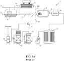
- Figure 1a shows a schematic of a prior art SCSA (single contact, single absorption) sulfuric acid plant recently disclosed in CA3021202 .
- SCSA single contact, single absorption
- overall improvements were obtained by combusting sulfur to sulfur dioxide using oxygen and submerged combustion.
- sulfuric acid plant designs allowed for single train capacities in excess of 10,000 mtpd with lower capital expenditure as well as enhanced energy recovery.
- the use of pure oxygen and submerged combustion provide advantages including: the gas volume involved is reduced and hence the equipment size by more than 70%; a main blower is not required since oxygen is received under pressure, thereby saving power; a drying tower system is eliminated since the supplied oxygen contains no moisture; low temperature submerged combustion allows for all-metal construction; high conversion can be achieved in a single pass; being a single absorption design, no reheat exchangers nor secondary absorption system are required; and enhanced energy recovery is obtained thereby producing more steam.
- molten sulfur 2 and pure oxygen 3 are supplied to submerged combustion reactor 4 and undergo a primary (submerged) combustion therein.
- Gas mixture 5a comprising sulfur dioxide and sulfur vapour is produced and is directed to sulfur condenser 6.
- Sulfur vapour in gas mixture 5a is condensed and removed therefrom as mixture 7 (comprising condensed liquid sulfur and a modest amount of sulfur dioxide).
- the resulting gas mixture 5d comprising sulfur dioxide and residual sulfur vapour is directed to secondary combustion chamber 8.
- An additional amount of pure oxygen 3 is also supplied to secondary combustion chamber 8 and undergoes a secondary combustion with the residual sulfur in gas mixture 5d. Essentially all residual sulfur vapour is reacted (combusted) to produce process gas 9 suitable for the contact process.
- process gas 9 is directed to superheater 10 where it is cooled prior to conversion to sulfur trioxide in contact apparatus 11 (e.g. a CORE-S TM tubular reactor cooled by molten salt).
- contact apparatus 11 e.g. a CORE-S TM tubular reactor cooled by molten salt.
- the produced sulfur trioxide is directed to economizer 12, then to optional hot absorption system 13, and then to cold absorption system 14 in which sulfur trioxide is absorbed in sulfuric acid to produce more concentrated sulfuric acid product.
- SCSA plant 1 also comprises purge gas cleaning unit 15 (in which a small amount of gas, essentially containing all the inert gases that enter the system with the oxygen are removed to prevent their accumulation) and SOz blower 16 (which recycles unreacted SOz and Oz gas obtained from cold absorption system 14 for further conversion to sulfur trioxide).
- purge gas cleaning unit 15 in which a small amount of gas, essentially containing all the inert gases that enter the system with the oxygen are removed to prevent their accumulation
- SOz blower 16 which recycles unreacted SOz and Oz gas obtained from cold absorption system 14 for further conversion to sulfur trioxide.
- the schematic of SCSA plant 1 of Figure 1a has been simplified to focus on the main components and systems involved.
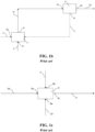
- FIGS. 1b and 1c are directly solely to the SOz production system in SCSA plant 1 and show the primary and secondary combustion parts respectively.
- molten sulfur 2 and pure oxygen 3 (> 90% purity by volume) are shown supplied to submerged combustion reactor 4 at inlets 4a and 4b respectively and undergo a primary (submerged) combustion therein.
- Gas mixture 5a comprising sulfur dioxide and sulfur vapour is produced and is directed from outlet 4c to inlet 6a of sulfur condenser 6.
- Sulfur vapour in gas mixture 5a is condensed and removed therefrom in mixture 7i (which comprises condensed liquid sulfur and a modest amount of dissolved sulfur dioxide) at outlet 6c.
- the resulting gas mixture 5d comprising sulfur dioxide and residual sulfur vapour is obtained from outlet 6b and directed to a secondary combustion stage.
- gas mixture 5d from sulfur condenser 6 is directed to inlet 8a of secondary combustion chamber 8.
- oxygen containing gas any oxygen containing gas may be used in the secondary combustion, conveniently pure oxygen 3 is also supplied to secondary combustion chamber 8 at inlet 8b.
- the residual sulfur vapour in gas mixture 5d undergoes secondary combustion with the supplied oxygen, essentially to completion, to produce SOz process gas 9 which is obtained from outlet 8c.
- Recycle gas 19 from cold absorption system 14 is also seen here being supplied to secondary combustion chamber 8 at inlet 8d.
- SCSA plant 1 provides many advantages, undesirably a substantial amount of sulfur vapour needs to be condensed in sulfur condenser 6.
- FIG. 2 A SCSA plant of the invention is next illustrated in the schematic of Figure 2 .
- Figure 2 With the exception of the primary combustion part of the plant, everything else about the inventive SCSA plant can be the same as that shown in Figure 1a .
- Figure 2 only shows the primary combustion part of the inventive SCSA plant and the differences between it and the prior art are readily apparent (e.g. by comparing Figure 2 to Figure 1b ).
- the primary combustion part differs from Figure 1b in that vapour phase combustion chamber 17 and heat exchanger 18 have been incorporated.
- Molten sulfur 2 and pure oxygen 3 are again supplied to submerged combustion reactor 4 at inlets 4a and 4b respectively and undergo a primary (submerged) combustion therein.
- First gas mixture 5a comprising sulfur dioxide and sulfur vapour is again produced but this time is directed from outlet 4c to inlet 17a of vapour phase combustion chamber 17.
- Pure oxygen 3 is also supplied to vapour phase combustion chamber 17 at inlet 17b and further primary vapour phase combustion takes place therein.
- Second gas mixture 5b is obtained from outlet 17c and comprises significantly more SOz and greater amounts of S allotropes in which n is less than about 5.
- Second gas mixture 5b is directed to heat exchanger 18 at inlet 18a whereupon it is cooled and output as cooler third gas mixture 5c from outlet 18b.
- heat exchanger 18 is depicted as a single component, but cooling may for instance be accomplished in one or more stages using one or more units.
- Third gas mixture 5c is next directed to inlet 6a of sulfur condenser 6 where sulfur vapour is condensed and removed therefrom in mixture 7ii at outlet 6c.
- the resulting fourth gas mixture 5d here is obtained from outlet 6b and directed to the secondary combustion stage.
- any known or conventional vapour phase combustion chamber types may be considered for use as vapour phase combustion chamber 6.
- any known or conventional gas-gas (e.g. steam superheater) or gas-liquid (e.g. steam boiler or molten salt cooler) heat exchangers may be considered for use as heat exchanger 18.
- the function of the heat exchanger 18 and sulfur condenser 6 can be carried out in a single, integrated piece of equipment.
- the various supplies of pure oxygen can be obtained from a common supply (e.g. a vacuum swing absorption unit, typically 90-93% purity, or a cryogenic air separation unit, typically > 98% purity, are likely sources) or alternatively more than one supply may be considered.
- a characteristic of the present invention is that the apparatus and operation results in the average number n average of the sulfur atoms in the sulfur molecules in the second gas mixture 5b being at least 20% lower than the n average of the sulfur atoms in the sulfur molecules in the first gas mixture 5a. More particularly, the average number n average of the sulfur atoms in the sulfur molecules in the second gas mixture 5b may be more than 50% lower than the n average of the sulfur atoms in the sulfur molecules in the first gas mixture 5a. Further, sulfur condenser 6 can be sized smaller than that used in the prior art, e.g. sized to condense less than 10 times the mass of molten sulfur supplied to the submerged combustion reactor.
- the cooling performed in heat exchanger 18 may preferably be carried out at a temperature above the dewpoint of sulfur and such cooling can remove more than 50% of the energy released during the combustion of sulfur in the submerged combustion and vapour phase combusting steps.
- the average number of sulfur atoms of the S n molecules for all n ⁇ 2 in the first, second, and third gas mixtures can be in the ranges from 6.4 to 7.0, 2.1 to 3, and 6.4 to 7.0 respectively.
- the temperature of the first gas mixture can be in the range from 440 to 500 °C
- the temperature of the second gas mixture can be in the range from 650 to 700 °C
- the temperature of the third gas mixture can be in the range from 400 to 450 °C.
- a main advantage of using submerged combustion using enriched air or pure oxygen at >90% concentration is that the temperature of the combustion products are limited to the boiling point of sulfur (e.g. -450 °C at 0.5 barg & ⁇ 575°C at 4 barg).
- the relatively low latent heat of sulfur a large amount of sulfur is evaporated from the bath resulting in large gas volumes that have to be handled.
- large amounts of sulfur need to be condensed from the SOz gas before it is sent for further use.
- the sulfur condenser in the system needs to operate at either high or low temperature to avoid the sulfur viscosity peak at 170°C, but even at the expected operating temperature of 275 - 300°C, the condensed liquid sulfur has high viscosity. This makes the sulfur more difficult to condense and the condensed sulfur liquid flows slowly requiring oversized pipes.
- the present invention splits the sulfur combustion into two portions, namely submerged and vapour phase combustion.
- the released reaction energy in the latter is used to heat the sulfur vapour and produce S 2 molecules.
- the vapour Due to the reaction of S 6 , S 7 and S 8 to S 2 molecules, the vapour has a very high apparent heat capacity and the vapour only increases relatively modestly in temperature to (e.g. to ⁇ 700°C instead of the ⁇ 2000 °C that would be expected based on conventional heat capacity alone).
- the process temperature (and hence oxygen addition) is preferably limited to about 700°C to ensure some of the sulfur molecules remain in the S 6 , S 7 and S 8 form which prevents temperature spikes in case of process fluctuations.
- the reaction of sulfur to sulfur dioxide in the gas phase has the additional benefit that significantly less sulfur remains in the gas before it is cooled resulting in smaller equipment for condensing the remaining sulfur.
- first gas mixture 5a is produced whose composition includes sulfur dioxide and sulfur vapour comprising molecules of sulfur S n in which n ranges from 2 to 8 and at a temperature of 486 °C.
- This first gas mixture 5a is directed to sulfur condenser 6 from which are output two mixtures, both at 295 °C, namely: 1406 kg/hr of mixture 7i containing condensed liquid sulfur in various allotropic forms and a modest amount of SOz; and 182.5 kg.hr of gas mixture 5d primarily containing SOz (i.e. 97% by mole) and residual sulfur vapour.
- the former condensed sulfur mixture is returned to submerged combustion reactor 4.
- the latter, primarily SOz, gas mixture is directed to a secondary combustion chamber as depicted in Figure 1c .
- the 182.5 kg/hr gas mixture primarily containing SOz from Figure 1b and 66 kg/hr of pure oxygen are directed to secondary combustion chamber 8 where the residual sulfur vapour in the former is fully combusted to produce 360 kg/hr process gas consisting essentially of sulfur dioxide and oxygen at about 600 °C.
- pure sulfur 2 and pure oxygen 3 are supplied to the submerged combustion reactor 4 in amounts of 100 and 29.3 kg/hr and at temperatures of 25 and 140 °C respectively. Except that less oxygen is supplied at this stage, this is the same as that of the preceding Comparative example.
- This time only 576 kg/hr of first gas mixture 5a is produced but with the same relative composition and at the same temperature as that of Comparative example 1.
- this first gas mixture 5a is directed next to vapour phase combustion chamber 17 and combusted with a further 53.2 kg/hr of pure oxygen at 25 °C (i.e. the same oxygen total of 82.5 kg/hr as in the Comparative example).
- the same amount and composition of gas mixture 5d is produced.
- the other mixture produced 7ii (containing condensed liquid sulfur in various allotropic forms and a modest amount of SOz) and to be returned to submerged combustion reactor 4 has the same relative composition as that of mixture 7i in the Comparative example but much less of it is produced (i.e. 446 kg/hr instead of 1406 kg/hr).
- the fourth gas mixture 5d which is essentially identical to that in the Comparative example, is directed to a secondary combustion chamber as depicted in Figure 1c .
- Inventive example 2 shows the same inventive process but differs from Inventive example 1 in that the sulfur condenser is operated at a temperature below the sulfur viscosity peak. It also illustrates that the inventive process can be operated at different pressures. Values for Inventive example 2 are tabulated in Table 3 below. Table 3. Inventive example 2 Stream (as per Fig.
- the sulfur condenser required in the inventive embodiments of Inventive examples 1 and 2 can be sized much smaller than that of the Comparative example.
- the ratio of mass supplied to the sulfur condenser in Figure 2 compared to that of Figure 1 is 628/1589 or 0.40.
- the amount of sulfur condensed in the Comparative example embodiment is 99.8% of 1406 kg/hr, which is substantially more than 10 times the amount of molten sulfur supplied to the submerged combustion reaction.
- the amount of sulfur condensed in the Inventive example 1 embodiment is 99.8% of 446 kg/hr, which is substantially less than 10 times the amount of molten sulfur supplied to the submerged combustion reaction.
- the calculated heat loads (i.e. the amount of energy that is removed from the process) from sulfur condenser 6 and from the heat exchanger 18 are shown in Tables 1 through 3.
- the total heat load in Inventive example 1 is the same as that in the Comparative Example, but importantly in this inventive process, more than 70% of that total heat load can be recovered in heat exchanger 18 which operates at a temperature above 400°C and less than 30% of the heat load is recovered from sulfur condenser 6 at much lower temperature.
- the energy recovered from heat exchanger 18 is recovered at higher temperature and has more economical value and can be used for high pressure (e.g. 60 barg) steam production and/or steam superheating. No condensation occurs in heat exchanger 18 and thus no viscous liquid needs to be dealt with to recover this energy.
- the total heat load shown in Table 3 for Inventive example 2 is higher compared to the other examples as due to the lower condensing temperature in the sulfur condenser there is less sulfur vapour leaving in stream 5d and therefore more of the molten sulfur in stream 1 is converted into sulfur dioxide. However, as for Inventive example 1, approximately 70% of the total heat load can be recovered in heat exchanger 18.
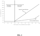
- Figure 3 compares the actual temperature of the gas mixture during the submerged and vapour phase combusting steps in Inventive example 1 to the expected temperature during these steps if a single sulfur allotrope were assumed to be present in the mixture throughout which is normal for most gases. It is evident from Figure 3 that the presence of the other sulfur allotropes results in an enormous difference between the actual gas temperature and the temperatures based on the single allotrope assumption during this vapour phase combusting step.
Landscapes
- Chemical & Material Sciences (AREA)
- Organic Chemistry (AREA)
- Inorganic Chemistry (AREA)
- Treating Waste Gases (AREA)
- Organic Low-Molecular-Weight Compounds And Preparation Thereof (AREA)
Priority Applications (1)
| Application Number | Priority Date | Filing Date | Title |
|---|---|---|---|
| MA63193A MA63193B1 (fr) | 2020-09-09 | 2021-08-13 | Système et procédé de production de dioxyde de soufre et installation d'acide sulfurique associée |
Applications Claiming Priority (2)
| Application Number | Priority Date | Filing Date | Title |
|---|---|---|---|
| US202063076165P | 2020-09-09 | 2020-09-09 | |
| PCT/US2021/045989 WO2022055662A1 (en) | 2020-09-09 | 2021-08-13 | System and method for producing sulfur dioxide and associated sulfuric acid plant |
Publications (2)
| Publication Number | Publication Date |
|---|---|
| EP4211073A1 EP4211073A1 (en) | 2023-07-19 |
| EP4211073B1 true EP4211073B1 (en) | 2024-10-30 |
Family
ID=77711425
Family Applications (1)
| Application Number | Title | Priority Date | Filing Date |
|---|---|---|---|
| EP21769227.6A Active EP4211073B1 (en) | 2020-09-09 | 2021-08-13 | System and method for producing sulfur dioxide and associated sulfuric acid plant |
Country Status (9)
| Country | Link |
|---|---|
| US (1) | US20230416089A1 (es) |
| EP (1) | EP4211073B1 (es) |
| CN (1) | CN116113598B (es) |
| AU (1) | AU2021340545A1 (es) |
| ES (1) | ES3002964T3 (es) |
| FI (1) | FI4211073T3 (es) |
| LT (1) | LT4211073T (es) |
| MA (1) | MA63193B1 (es) |
| WO (1) | WO2022055662A1 (es) |
Families Citing this family (1)
| Publication number | Priority date | Publication date | Assignee | Title |
|---|---|---|---|---|
| US20240067522A1 (en) * | 2022-08-24 | 2024-02-29 | Hunan Fortune Environmental Technology Co., Ltd. | Resource utilization method of crude sodium sulfate |
Family Cites Families (12)
| Publication number | Priority date | Publication date | Assignee | Title |
|---|---|---|---|---|
| BE792062A (fr) | 1971-12-02 | 1973-05-29 | Bayer Ag | Procede de production continue d'anhydride sulfureux de grande purete |
| US4046867A (en) * | 1975-02-25 | 1977-09-06 | Allied Chemical Corporation | Method for making sulfur dioxide-containing gas stream |
| US5204082A (en) | 1991-07-18 | 1993-04-20 | C.F. Braun Inc. | Sulfur dioxide generation by submerged combustion and reduced thermal cycling by use of a hot recycle of sulfur |
| GB0316433D0 (en) * | 2003-07-14 | 2003-08-20 | Boc Group Plc | Process for recovering sulphur from a gas stream containing hydrogen sulphide |
| DE102006006460A1 (de) * | 2006-02-10 | 2007-08-30 | Outokumpu Technology Oy | Verfahren und Vorrichtung zur Verbrennung von Schwefel |
| BRPI0704106B1 (pt) * | 2006-09-25 | 2017-04-25 | Haldor Topsoe As | processo para a produção de ácido sulfúrico |
| DE102006051899A1 (de) | 2006-10-31 | 2008-05-15 | Bayer Technology Services Gmbh | Verfahren und Vorrichtung zur katalytischen Oxidation von SO2-haltigen Gasen mit Sauerstoff |
| EP2507164B1 (de) | 2009-12-01 | 2017-10-18 | Chemetics, Inc. | Verfahren zur herstellung von schwefelsäure |
| SI2330075T1 (sl) | 2009-12-01 | 2015-12-31 | Bayer Intellectual Property Gmbh | Postopek izdelave žveplove kisline |
| CA2802885A1 (en) | 2013-01-17 | 2013-04-01 | Chemetics Inc. | Efficient system for producing sulfuric acid using a spray tower |
| US10239756B1 (en) * | 2017-11-29 | 2019-03-26 | Saudi Arabian Oil Company | Process for sulfur recovery from acid gas stream without catalytic Claus reactors |
| CA3021202A1 (en) * | 2018-10-17 | 2018-12-24 | Chemetics Inc. | Sulphuric acid plant |
-
2021
- 2021-08-13 EP EP21769227.6A patent/EP4211073B1/en active Active
- 2021-08-13 LT LTEPPCT/US2021/045989T patent/LT4211073T/lt unknown
- 2021-08-13 AU AU2021340545A patent/AU2021340545A1/en active Pending
- 2021-08-13 MA MA63193A patent/MA63193B1/fr unknown
- 2021-08-13 FI FIEP21769227.6T patent/FI4211073T3/fi active
- 2021-08-13 CN CN202180054493.5A patent/CN116113598B/zh active Active
- 2021-08-13 US US18/044,677 patent/US20230416089A1/en active Pending
- 2021-08-13 ES ES21769227T patent/ES3002964T3/es active Active
- 2021-08-13 WO PCT/US2021/045989 patent/WO2022055662A1/en not_active Ceased
Also Published As
| Publication number | Publication date |
|---|---|
| AU2021340545A1 (en) | 2023-05-11 |
| CN116113598B (zh) | 2025-03-25 |
| ES3002964T3 (en) | 2025-03-10 |
| FI4211073T3 (fi) | 2024-12-16 |
| LT4211073T (lt) | 2025-01-10 |
| CN116113598A (zh) | 2023-05-12 |
| EP4211073A1 (en) | 2023-07-19 |
| WO2022055662A1 (en) | 2022-03-17 |
| MA63193B1 (fr) | 2024-12-31 |
| US20230416089A1 (en) | 2023-12-28 |
Similar Documents
| Publication | Publication Date | Title |
|---|---|---|
| US5503821A (en) | Methods for recovering high grade process energy from a contact sulfuric acid process | |
| US4298588A (en) | Ammonia production process | |
| US5130112A (en) | Method for recovering high grade process energy from a contact sulfuric acid process | |
| KR100786409B1 (ko) | 황화수소를 함유하는 기체 스트림의 처리 | |
| US4632818A (en) | Production of sulfur from an oxygen enriched claus system | |
| US5118490A (en) | Absorption of wet conversion gas | |
| US4046866A (en) | Production of liquid sulfur trioxide | |
| JPS6241702A (ja) | 硫化水素含有ガス流からの硫黄回収方法 | |
| EP3472096B1 (en) | Integrated process for the production of sulphuric acid and sulphur | |
| US12528752B2 (en) | Integrated ammonia and sulfuric acid production plant and process | |
| CA3021202A1 (en) | Sulphuric acid plant | |
| JPS61222908A (ja) | 硫黄回収方法及び装置 | |
| Yadav et al. | Numerical investigation of 660 MW pulverized coal-fired supercritical power plant retrofitted to oxy-coal combustion | |
| US5194239A (en) | Oxygen-based noncatalytic sulfuric acid process | |
| US20090220402A1 (en) | Novel sulfur recovery plant | |
| EP4211073B1 (en) | System and method for producing sulfur dioxide and associated sulfuric acid plant | |
| US20250033967A1 (en) | Systems and methods for producing sulfuric acid or liquefied sulfur dioxide | |
| US4798716A (en) | Sulfur recovery plant and process using oxygen | |
| CA3141027A1 (en) | Systems and methods for producing sulfuric acid or liquefied sulfur dioxide | |
| US5863513A (en) | Treatment of gas | |
| BR112023027748B1 (pt) | Processo de produção de ácido nítrico e usina com unidade de fornecimento de oxigênio | |
| BR112022011495B1 (pt) | Usinas integradas para produzir amônia e ácido sulfúrico e fertilizante e processos integrados para a produção de amônia e ácido sulfúrico e fertilizantes de fosfato diamônico e fosfato monoamônico | |
| WO2009027494A2 (en) | Method for treating a gaseous hydrocarbon stream comprising hydrogen sulphide | |
| GB1602108A (en) | Catalytic process |
Legal Events
| Date | Code | Title | Description |
|---|---|---|---|
| STAA | Information on the status of an ep patent application or granted ep patent |
Free format text: STATUS: UNKNOWN |
|
| STAA | Information on the status of an ep patent application or granted ep patent |
Free format text: STATUS: THE INTERNATIONAL PUBLICATION HAS BEEN MADE |
|
| PUAI | Public reference made under article 153(3) epc to a published international application that has entered the european phase |
Free format text: ORIGINAL CODE: 0009012 |
|
| STAA | Information on the status of an ep patent application or granted ep patent |
Free format text: STATUS: REQUEST FOR EXAMINATION WAS MADE |
|
| 17P | Request for examination filed |
Effective date: 20230220 |
|
| AK | Designated contracting states |
Kind code of ref document: A1 Designated state(s): AL AT BE BG CH CY CZ DE DK EE ES FI FR GB GR HR HU IE IS IT LI LT LU LV MC MK MT NL NO PL PT RO RS SE SI SK SM TR |
|
| DAX | Request for extension of the european patent (deleted) | ||
| RAV | Requested validation state of the european patent: fee paid |
Extension state: MA Effective date: 20230220 |
|
| GRAP | Despatch of communication of intention to grant a patent |
Free format text: ORIGINAL CODE: EPIDOSNIGR1 |
|
| STAA | Information on the status of an ep patent application or granted ep patent |
Free format text: STATUS: GRANT OF PATENT IS INTENDED |
|
| INTG | Intention to grant announced |
Effective date: 20240607 |
|
| GRAS | Grant fee paid |
Free format text: ORIGINAL CODE: EPIDOSNIGR3 |
|
| GRAA | (expected) grant |
Free format text: ORIGINAL CODE: 0009210 |
|
| STAA | Information on the status of an ep patent application or granted ep patent |
Free format text: STATUS: THE PATENT HAS BEEN GRANTED |
|
| AK | Designated contracting states |
Kind code of ref document: B1 Designated state(s): AL AT BE BG CH CY CZ DE DK EE ES FI FR GB GR HR HU IE IS IT LI LT LU LV MC MK MT NL NO PL PT RO RS SE SI SK SM TR |
|
| REG | Reference to a national code |
Ref country code: GB Ref legal event code: FG4D |
|
| REG | Reference to a national code |
Ref country code: CH Ref legal event code: EP |
|
| P01 | Opt-out of the competence of the unified patent court (upc) registered |
Free format text: CASE NUMBER: APP_53282/2024 Effective date: 20240925 |
|
| REG | Reference to a national code |
Ref country code: IE Ref legal event code: FG4D |
|
| REG | Reference to a national code |
Ref country code: DE Ref legal event code: R096 Ref document number: 602021021070 Country of ref document: DE |
|
| REG | Reference to a national code |
Ref country code: FI Ref legal event code: FGE |
|
| REG | Reference to a national code |
Ref country code: MA Ref legal event code: VAGR Ref document number: 63193 Country of ref document: MA Kind code of ref document: B1 |
|
| REG | Reference to a national code |
Ref country code: NL Ref legal event code: MP Effective date: 20241030 |
|
| REG | Reference to a national code |
Ref country code: ES Ref legal event code: FG2A Ref document number: 3002964 Country of ref document: ES Kind code of ref document: T3 Effective date: 20250310 |
|
| PG25 | Lapsed in a contracting state [announced via postgrant information from national office to epo] |
Ref country code: PT Free format text: LAPSE BECAUSE OF FAILURE TO SUBMIT A TRANSLATION OF THE DESCRIPTION OR TO PAY THE FEE WITHIN THE PRESCRIBED TIME-LIMIT Effective date: 20250228 Ref country code: IS Free format text: LAPSE BECAUSE OF FAILURE TO SUBMIT A TRANSLATION OF THE DESCRIPTION OR TO PAY THE FEE WITHIN THE PRESCRIBED TIME-LIMIT Effective date: 20250228 Ref country code: HR Free format text: LAPSE BECAUSE OF FAILURE TO SUBMIT A TRANSLATION OF THE DESCRIPTION OR TO PAY THE FEE WITHIN THE PRESCRIBED TIME-LIMIT Effective date: 20241030 |
|
| PG25 | Lapsed in a contracting state [announced via postgrant information from national office to epo] |
Ref country code: NL Free format text: LAPSE BECAUSE OF FAILURE TO SUBMIT A TRANSLATION OF THE DESCRIPTION OR TO PAY THE FEE WITHIN THE PRESCRIBED TIME-LIMIT Effective date: 20241030 |
|
| REG | Reference to a national code |
Ref country code: AT Ref legal event code: MK05 Ref document number: 1736750 Country of ref document: AT Kind code of ref document: T Effective date: 20241030 |
|
| PG25 | Lapsed in a contracting state [announced via postgrant information from national office to epo] |
Ref country code: GR Free format text: LAPSE BECAUSE OF FAILURE TO SUBMIT A TRANSLATION OF THE DESCRIPTION OR TO PAY THE FEE WITHIN THE PRESCRIBED TIME-LIMIT Effective date: 20250131 Ref country code: LV Free format text: LAPSE BECAUSE OF FAILURE TO SUBMIT A TRANSLATION OF THE DESCRIPTION OR TO PAY THE FEE WITHIN THE PRESCRIBED TIME-LIMIT Effective date: 20241030 Ref country code: AT Free format text: LAPSE BECAUSE OF FAILURE TO SUBMIT A TRANSLATION OF THE DESCRIPTION OR TO PAY THE FEE WITHIN THE PRESCRIBED TIME-LIMIT Effective date: 20241030 |
|
| PG25 | Lapsed in a contracting state [announced via postgrant information from national office to epo] |
Ref country code: PL Free format text: LAPSE BECAUSE OF FAILURE TO SUBMIT A TRANSLATION OF THE DESCRIPTION OR TO PAY THE FEE WITHIN THE PRESCRIBED TIME-LIMIT Effective date: 20241030 |
|
| PG25 | Lapsed in a contracting state [announced via postgrant information from national office to epo] |
Ref country code: RS Free format text: LAPSE BECAUSE OF FAILURE TO SUBMIT A TRANSLATION OF THE DESCRIPTION OR TO PAY THE FEE WITHIN THE PRESCRIBED TIME-LIMIT Effective date: 20250130 |
|
| PG25 | Lapsed in a contracting state [announced via postgrant information from national office to epo] |
Ref country code: SM Free format text: LAPSE BECAUSE OF FAILURE TO SUBMIT A TRANSLATION OF THE DESCRIPTION OR TO PAY THE FEE WITHIN THE PRESCRIBED TIME-LIMIT Effective date: 20241030 |
|
| PG25 | Lapsed in a contracting state [announced via postgrant information from national office to epo] |
Ref country code: DK Free format text: LAPSE BECAUSE OF FAILURE TO SUBMIT A TRANSLATION OF THE DESCRIPTION OR TO PAY THE FEE WITHIN THE PRESCRIBED TIME-LIMIT Effective date: 20241030 |
|
| PG25 | Lapsed in a contracting state [announced via postgrant information from national office to epo] |
Ref country code: EE Free format text: LAPSE BECAUSE OF FAILURE TO SUBMIT A TRANSLATION OF THE DESCRIPTION OR TO PAY THE FEE WITHIN THE PRESCRIBED TIME-LIMIT Effective date: 20241030 |
|
| PG25 | Lapsed in a contracting state [announced via postgrant information from national office to epo] |
Ref country code: RO Free format text: LAPSE BECAUSE OF FAILURE TO SUBMIT A TRANSLATION OF THE DESCRIPTION OR TO PAY THE FEE WITHIN THE PRESCRIBED TIME-LIMIT Effective date: 20241030 |
|
| PG25 | Lapsed in a contracting state [announced via postgrant information from national office to epo] |
Ref country code: SK Free format text: LAPSE BECAUSE OF FAILURE TO SUBMIT A TRANSLATION OF THE DESCRIPTION OR TO PAY THE FEE WITHIN THE PRESCRIBED TIME-LIMIT Effective date: 20241030 |
|
| PG25 | Lapsed in a contracting state [announced via postgrant information from national office to epo] |
Ref country code: CZ Free format text: LAPSE BECAUSE OF FAILURE TO SUBMIT A TRANSLATION OF THE DESCRIPTION OR TO PAY THE FEE WITHIN THE PRESCRIBED TIME-LIMIT Effective date: 20241030 |
|
| PG25 | Lapsed in a contracting state [announced via postgrant information from national office to epo] |
Ref country code: IT Free format text: LAPSE BECAUSE OF FAILURE TO SUBMIT A TRANSLATION OF THE DESCRIPTION OR TO PAY THE FEE WITHIN THE PRESCRIBED TIME-LIMIT Effective date: 20241030 |
|
| REG | Reference to a national code |
Ref country code: DE Ref legal event code: R097 Ref document number: 602021021070 Country of ref document: DE |
|
| PLBE | No opposition filed within time limit |
Free format text: ORIGINAL CODE: 0009261 |
|
| STAA | Information on the status of an ep patent application or granted ep patent |
Free format text: STATUS: NO OPPOSITION FILED WITHIN TIME LIMIT |
|
| PG25 | Lapsed in a contracting state [announced via postgrant information from national office to epo] |
Ref country code: SE Free format text: LAPSE BECAUSE OF FAILURE TO SUBMIT A TRANSLATION OF THE DESCRIPTION OR TO PAY THE FEE WITHIN THE PRESCRIBED TIME-LIMIT Effective date: 20241030 |
|
| 26N | No opposition filed |
Effective date: 20250731 |
|
| PGFP | Annual fee paid to national office [announced via postgrant information from national office to epo] |
Ref country code: FI Payment date: 20250822 Year of fee payment: 5 Ref country code: ES Payment date: 20250926 Year of fee payment: 5 |
|
| PGFP | Annual fee paid to national office [announced via postgrant information from national office to epo] |
Ref country code: LT Payment date: 20250723 Year of fee payment: 5 Ref country code: DE Payment date: 20250820 Year of fee payment: 5 |
|
| PGFP | Annual fee paid to national office [announced via postgrant information from national office to epo] |
Ref country code: NO Payment date: 20250826 Year of fee payment: 5 |
|
| PGFP | Annual fee paid to national office [announced via postgrant information from national office to epo] |
Ref country code: BG Payment date: 20250822 Year of fee payment: 5 Ref country code: BE Payment date: 20250820 Year of fee payment: 5 |
|
| VSFP | Annual fee paid to validation state [announced via postgrant information from national office to epo] |
Ref country code: MA Payment date: 20250801 Year of fee payment: 5 |
|
| REG | Reference to a national code |
Ref country code: CH Ref legal event code: H13 Free format text: ST27 STATUS EVENT CODE: U-0-0-H10-H13 (AS PROVIDED BY THE NATIONAL OFFICE) Effective date: 20260324 |
|
| PG25 | Lapsed in a contracting state [announced via postgrant information from national office to epo] |
Ref country code: MC Free format text: LAPSE BECAUSE OF FAILURE TO SUBMIT A TRANSLATION OF THE DESCRIPTION OR TO PAY THE FEE WITHIN THE PRESCRIBED TIME-LIMIT Effective date: 20241030 |
|
| PG25 | Lapsed in a contracting state [announced via postgrant information from national office to epo] |
Ref country code: LU Free format text: LAPSE BECAUSE OF NON-PAYMENT OF DUE FEES Effective date: 20250813 |