EP4210442A1 - Mechanical enclosure - Google Patents
Mechanical enclosure Download PDFInfo
- Publication number
- EP4210442A1 EP4210442A1 EP23151029.8A EP23151029A EP4210442A1 EP 4210442 A1 EP4210442 A1 EP 4210442A1 EP 23151029 A EP23151029 A EP 23151029A EP 4210442 A1 EP4210442 A1 EP 4210442A1
- Authority
- EP
- European Patent Office
- Prior art keywords
- compartment
- cooling
- fins
- enclosure
- cavity
- Prior art date
- Legal status (The legal status is an assumption and is not a legal conclusion. Google has not performed a legal analysis and makes no representation as to the accuracy of the status listed.)
- Pending
Links
Images



Classifications
-
- H—ELECTRICITY
- H05—ELECTRIC TECHNIQUES NOT OTHERWISE PROVIDED FOR
- H05K—PRINTED CIRCUITS; CASINGS OR CONSTRUCTIONAL DETAILS OF ELECTRIC APPARATUS; MANUFACTURE OF ASSEMBLAGES OF ELECTRICAL COMPONENTS
- H05K7/00—Constructional details common to different types of electric apparatus
- H05K7/20—Modifications to facilitate cooling, ventilating, or heating
- H05K7/2089—Modifications to facilitate cooling, ventilating, or heating for power electronics, e.g. for inverters for controlling motor
- H05K7/20909—Forced ventilation, e.g. on heat dissipaters coupled to components
- H05K7/20918—Forced ventilation, e.g. on heat dissipaters coupled to components the components being isolated from air flow, e.g. hollow heat sinks, wind tunnels or funnels
-
- H—ELECTRICITY
- H05—ELECTRIC TECHNIQUES NOT OTHERWISE PROVIDED FOR
- H05K—PRINTED CIRCUITS; CASINGS OR CONSTRUCTIONAL DETAILS OF ELECTRIC APPARATUS; MANUFACTURE OF ASSEMBLAGES OF ELECTRICAL COMPONENTS
- H05K7/00—Constructional details common to different types of electric apparatus
- H05K7/20—Modifications to facilitate cooling, ventilating, or heating
- H05K7/2089—Modifications to facilitate cooling, ventilating, or heating for power electronics, e.g. for inverters for controlling motor
- H05K7/209—Heat transfer by conduction from internal heat source to heat radiating structure
-
- H—ELECTRICITY
- H02—GENERATION; CONVERSION OR DISTRIBUTION OF ELECTRIC POWER
- H02M—APPARATUS FOR CONVERSION BETWEEN AC AND AC, BETWEEN AC AND DC, OR BETWEEN DC AND DC, AND FOR USE WITH MAINS OR SIMILAR POWER SUPPLY SYSTEMS; CONVERSION OF DC OR AC INPUT POWER INTO SURGE OUTPUT POWER; CONTROL OR REGULATION THEREOF
- H02M1/00—Details of apparatus for conversion
-
- H—ELECTRICITY
- H05—ELECTRIC TECHNIQUES NOT OTHERWISE PROVIDED FOR
- H05K—PRINTED CIRCUITS; CASINGS OR CONSTRUCTIONAL DETAILS OF ELECTRIC APPARATUS; MANUFACTURE OF ASSEMBLAGES OF ELECTRICAL COMPONENTS
- H05K5/00—Casings, cabinets or drawers for electric apparatus
- H05K5/02—Details
- H05K5/0217—Mechanical details of casings
-
- H—ELECTRICITY
- H05—ELECTRIC TECHNIQUES NOT OTHERWISE PROVIDED FOR
- H05K—PRINTED CIRCUITS; CASINGS OR CONSTRUCTIONAL DETAILS OF ELECTRIC APPARATUS; MANUFACTURE OF ASSEMBLAGES OF ELECTRICAL COMPONENTS
- H05K5/00—Casings, cabinets or drawers for electric apparatus
- H05K5/06—Hermetically-sealed casings
-
- H—ELECTRICITY
- H05—ELECTRIC TECHNIQUES NOT OTHERWISE PROVIDED FOR
- H05K—PRINTED CIRCUITS; CASINGS OR CONSTRUCTIONAL DETAILS OF ELECTRIC APPARATUS; MANUFACTURE OF ASSEMBLAGES OF ELECTRICAL COMPONENTS
- H05K7/00—Constructional details common to different types of electric apparatus
- H05K7/14—Mounting supporting structure in casing or on frame or rack
-
- H—ELECTRICITY
- H05—ELECTRIC TECHNIQUES NOT OTHERWISE PROVIDED FOR
- H05K—PRINTED CIRCUITS; CASINGS OR CONSTRUCTIONAL DETAILS OF ELECTRIC APPARATUS; MANUFACTURE OF ASSEMBLAGES OF ELECTRICAL COMPONENTS
- H05K7/00—Constructional details common to different types of electric apparatus
- H05K7/14—Mounting supporting structure in casing or on frame or rack
- H05K7/1422—Printed circuit boards receptacles, e.g. stacked structures, electronic circuit modules or box like frames
- H05K7/1427—Housings
- H05K7/1432—Housings specially adapted for power drive units or power converters
-
- H—ELECTRICITY
- H05—ELECTRIC TECHNIQUES NOT OTHERWISE PROVIDED FOR
- H05K—PRINTED CIRCUITS; CASINGS OR CONSTRUCTIONAL DETAILS OF ELECTRIC APPARATUS; MANUFACTURE OF ASSEMBLAGES OF ELECTRICAL COMPONENTS
- H05K7/00—Constructional details common to different types of electric apparatus
- H05K7/14—Mounting supporting structure in casing or on frame or rack
- H05K7/1422—Printed circuit boards receptacles, e.g. stacked structures, electronic circuit modules or box like frames
- H05K7/1427—Housings
- H05K7/1432—Housings specially adapted for power drive units or power converters
- H05K7/14322—Housings specially adapted for power drive units or power converters wherein the control and power circuits of a power converter are arranged within the same casing
-
- H—ELECTRICITY
- H05—ELECTRIC TECHNIQUES NOT OTHERWISE PROVIDED FOR
- H05K—PRINTED CIRCUITS; CASINGS OR CONSTRUCTIONAL DETAILS OF ELECTRIC APPARATUS; MANUFACTURE OF ASSEMBLAGES OF ELECTRICAL COMPONENTS
- H05K7/00—Constructional details common to different types of electric apparatus
- H05K7/20—Modifications to facilitate cooling, ventilating, or heating
- H05K7/2089—Modifications to facilitate cooling, ventilating, or heating for power electronics, e.g. for inverters for controlling motor
- H05K7/20909—Forced ventilation, e.g. on heat dissipaters coupled to components
Definitions
- the invention relates generally to mechanical enclosures and, more specifically, to mechanical enclosures for power converters.
- Power converters may sometimes require high ingression protection (IP) rating as well as air-cooled thermal management.
- IP ingression protection
- a converter with a magnetic component may be needed to extend the operating voltage range.
- aspects of the disclosure relate to methods, apparatuses, and/or systems for manufacturing and assembling a mechanical enclosure for a power converter.
- a mechanical enclosure for a power converter comprises a base; a first compartment configured for receiving one or more electronic devices; and a second compartment configured for receiving a magnetic device, the second compartment formed by a cavity protruding from a bottom surface of the base.
- the mechanical enclosure may comprise one or more cooling systems.
- the one or more cooling systems may comprise: a first cooling system, operatively connected to an outer surface of the first compartment, the first cooling system configured for cooling the first compartment; and a second cooling system, operatively connected to an outer surface of the second compartment, the second cooling system configured for cooling the second compartment.
- the one or more cooling systems may comprise one or more cooling fins.
- the first cooling system may comprise a first set of cooling fins and the second cooling system may comprise a second set of cooling fins, and wherein the first and second set of cooling fins may have different orientations.
- the orientation of the first set of fins may be perpendicular to the second set of fins.
- the first set of cooling fins may protrude from an outer side of the bottom surface of the base.
- the second set of cooling fins may protrude from an outer wall of the cavity.
- the mechanical enclosure may comprise a fan configured to drive air through the one or more cooling systems.
- a method for manufacturing a mechanical enclosure for a power converter comprises providing a base; providing a first compartment for receiving one or more electronic devices; and providing a second compartment for receiving a magnetic device, the second compartment formed by a cavity protruding from a bottom surface of the base.
- the method may comprise providing one or more cooling systems.
- the one or more cooling systems may comprise: a first cooling system, operatively connected to an outer surface of the first compartment, the first cooling system configured for cooling the first compartment; and a second cooling system, operatively connected to an outer surface of the second compartment, the second cooling system configured for cooling the second compartment.
- the method may comprise providing a fan for driving air through the one or more cooling systems.
- the magnetic device may be pre-potted (e.g., the second compartment may be configured for receiving a pre-potted magnetic device).
- the invention provides a method for assembling a mechanical enclosure for a power converter, the method comprising: providing a base; providing a first compartment for receiving one or more electronic devices; providing a second compartment for receiving a magnetic device, the second compartment formed by a cavity protruding from a bottom surface of the base; pre-potting the magnetic device; placing the pre-potted magnetic device in the cavity; filling the remaining gap of cavity with additional potting material; and assembling the one or more electronic devices in the first compartment.
- a method for assembling a mechanical enclosure for a power converter comprises: providing a base; providing a first compartment for receiving one or more electronic devices; providing a second compartment for receiving a magnetic device, the second compartment formed by a cavity protruding from a bottom surface of the base; pre-potting the magnetic device; placing the pre-potted magnetic device in the cavity; and assembling the one or more or more electronic devices in the first compartment.
- an enclosure for a power converter may include electronic and magnetic devices.
- IP ingression protection
- the power converter may require a high-density mechanical enclosure.
- the IP rating require a degree of protection (of the magnetic device, the user, or the environment) against dust, particles, water, or other elements.
- a high-density mechanical enclosure configured for housing one or more electronic and magnetic devices while meeting a high IP rating.
- the enclosure may be configured to meet the IP67 requirements (dust-tight and can be immersed in one meter of water for up to 30 minutes). That said, the enclosure may be configured for meeting requirements for other IP ratings.
- the enclosure may be configured to dissipate heat (e.g., generated by the electronic and the magnetic devices) and provide cooling to the power converter.
- the enclosure may include one or more compartments.
- a first compartment may be configured for housing one or more electronic devices (e.g., semiconductor devices) and a second compartment may be configured for housing a magnetic device.
- the enclosure may include one or more sets of cooling systems for cooling the compartments where the electronic devices and the magnetic device are housed.
- the one or more cooling systems may include a first set of cooling fins for cooling the electronic devices.
- the first set of cooling system may be configured to extend from a bottom side of the first compartment.
- the one or more cooling systems may include a second set of fins for cooling the magnetic device.
- the second set of fins may extend from the outer sides of the second compartment.
- the first set and second set of fins may have different orientations.
- One or more fans may be used to drive air through the cooling fins.
- the one or more fans may be attached to a back side of the enclosure (e.g., adjacent to the electronic device compartment).
- the one or more fans may be configured to drive airflow through to the first set of fins and the second set of fins. Thereby cooling both compartments.
- FIG. 1 is a perspective view of a power converter 100.
- Power converter 100 may include an enclosure 110.
- Enclosure 110 includes a first compartment 112 configured to house one or more electronic devices.
- Enclosure 110 includes a second compartment 113 configured to house a magnetic device.
- Compartment 112 includes a first set of fins 182 configured for cooling second compartment 113.
- the first set of fins 182 and the second set of fins 186 are of different orientation (e.g., one set of fins may be viewed to be vertical and the other set of fins may be viewed to be horizontal).
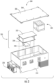
- FIG. 2 is an exploded view of a power converter 200.
- Power converter 200 may include an enclosure 210. Enclosure 210 may be configured to receive one or more components of the power converter.
- Power converter 200 may include a printed circuit board assembly 220, an electromagnetic device 230, a cover 260, fans 270, or other components.
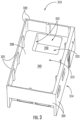
- FIG. 3 is a perspective view of an enclosure 310.
- Enclosure 310 may include one or more side walls 320, and a base 330.
- Side walls 320 may be configured to surround base 330.
- Side walls 320 may connect to one or more sides (or edges) of base 330.
- Side walls 320 may be configured to extend from base 330 towards a top side 312 of the enclosure 310 to form inner space 340 of the enclosure.
- Side walls 320 may extend from base 330 towards a bottom side 314 of enclosure 310 (opposite to top side 312).
- Side walls 320 may include a plurality of connecting spaces 325 configured for receiving connecting members to connect a cover to enclosure 310.
- Connecting spaces 325 may be in the form of holes, tabs, sleeves, casings, or other connecting space for receiving a connecting member.
- Connecting spaces 325 may be formed in walls 320 (e.g., integrally), or may be joined to walls 325 by other connecting means (glued, welded, screwed, etc.).
- FIG. 2 shows an example of a cover 260 configured for covering enclosure 210.
- Cover 260 may include one or more connecting spaces 265 configured for receiving connecting members (e.g., bolts, screws, pins, etc.) to connect cover 260 to enclosure 210.
- connecting members e.g., bolts, screws, pins, etc.
- One or more connecting spaces 265 may be configured to align with one or more connecting spaces 325 of the enclosure (to facilitate receiving the connecting members by connecting spaces 325).
- Connecting spaces 265 of the cover may be in the form of holes (or other forms configured for receiving connecting members or facilitating connection of the cover with the enclosure).
- inner space 340 of the enclosure may be defined by base 330 and side walls 320. Inner space 340 may be configured for receiving one or more electronic components. The area of inner space 340 that houses the electronic components may form the first compartment of the enclosure (as shown in FIG. 1 ).
- FIG. 2 shows an example of a printed circuit board assembly (PCBA) 220.
- PCBA 220 may include a control board 222, a power board 224, an insulated-gate bipolar transistor assembly (IGBT) 226, or other electronic components.
- IGBT insulated-gate bipolar transistor assembly
- base 330 may include a cavity 350.
- Cavity 350 may be configured to house a magnetic device (e.g., magnetic device 230 shown in FIG. 2 ). Cavity 350 protrudes downwardly from a bottom surface of base 330.
- Cavity 350 may include one or more side walls 352 and a bottom surface 353. The side walls 352 may connect to one or more sides (or edges) of bottom surface 353. Side walls 352 may be configured to extend from bottom surface 353 towards top side 312 of the enclosure 310 to form cavity 350.
- cavity 350 is for illustrative purposes only and is not intended to be limiting. It will be apparent to those skilled in the art, that other cavity shapes, dimensions, location, or other characteristics of the cavity may be used.
- cavity 350 may be formed based on an overall architecture of the power converter (e.g., in a shape, geometry, dimension, or location to accommodate the electromagnetic device or the other components of the power converter).
- a potting glue may be used to partially fill cavity 350.
- the potting glue may be disposed on the bottom surface 353 of cavity 350.
- the magnetic device may be disposed on the potting glue and gaps between the side walls 352 and the magnetic device may be completely filled with the potting glue without any gaps to stabilize the magnetic device within cavity 350. This is to ensure connectivity of the metal enclosure with the potting for heat transfer from the magnetic device to the enclosure. It is to be noted, as it will be apparent to those skilled in the art, that the amount of potting glue used to stabilize the magnetic device within cavity 350 may depend on the size or shape of cavity 350 and/or the electromagnetic device.
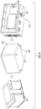
- FIG. 4 illustrates an exemplary assembly placing a magnetic device in a housing 432 that may be placed within an enclosure 410.
- Magnetic device 430 may be an inductor or transformer.
- Device 430 may be pre-potted within a housing 432 having one or more pegs 434 configured to support device 430 within cavity 450 of enclosure 410.
- Housing 432 may be configured to meet a high IP rating.
- housing 432 may have an IP rating of 67 (IP67).
- Housing 432 may be configured for other IP ratings.
- a cover 436 may be used to seal the magnetic device 430 in cavity 450.
- FIGs. 5 A-D illustrate multiple views of an enclosure 510.
- Enclosure 510 may include one or more cooling systems.
- the one or more cooling systems may include one or more sets of fins disposed on (or operatively connected to) the outer side of the enclosure to help with heat dissipation.
- the one or more sets of fins may extend from a base outer surface 532 of base 530, opposite the inner space of enclosure 510 (not shown here).
- Enclosure 510 may include a first set of fins 582 disposed on portion 534 of base outer side 532, opposite to the portion of the inner space that houses the printed circuit boards (placed on the first compartment).
- the first set of fins 582 may extend vertically from portion 534 of outer side 532 of base 530.
- the first set of fins 582 may be placed between portions 522 of side walls 520. This configuration of the first set of fins 582 may help dissipate heat of the power converter, especially heat from the printed circuit boards.
- Enclosure 510 may include a second set of fins 586.
- the second set of fins 586 may be disposed on (or protrude from) an outer surface 558 of side walls of the enclosure cavity 550 (e.g., placed on one or more sides of the second compartment).
- the second set of fins 586 may extend horizontally from both sides of cavity 550.
- the second set of fins 586 may help dissipate heat from the power converter, especially heat from the electromagnetic device.
- the first set of fins 582 and the second set of fins 586 may be disposed (or assembled) on outer surface 532 of base 530 such that the fins of the first set are perpendicular to the fins of the second set.
- One or more fans e.g., fans 270 shown in FIG.
- the one or more fans may be configured to drive air across the first set of fins 582. Air flow caused by the one or more fans may also be driven across the second set of fins 586 cooling cavity 550 as a result.
- the IP rating of the fan should meet the same requirement as the system.
- FIG. 6 shows a flow diagram illustrating an example of a method 600 for assembling a mechanical enclosure.
- an enclosure base may be provided.
- a base may be the same as or similar to base 330 (shown in FIG. 3 and described herein).
- a first compartment may be provided.
- the first compartment may be configured for receiving one or more electronic devices.
- the first compartment may be the same as or similar to inner space 340 (shown in FIG. 3 and described herein).
- a second compartment for receiving a magnetic device may be provided.
- the second compartment may be formed by a cavity protruding from a bottom surface of the base.
- Second compartment may be the same as or similar to cavity 350 (shown in FIG. 3 and described herein).
- a magnetic device may be placed in the second compartment.
- the magnetic device may be pre-potted before placing in the cavity.
- the magnetic device may be the same as or similar to magnetic device 430 (shown in FIG. 4 and described herein).
- one or more electronic devices may be assembled in the first compartment.
- the electronic device may be the same as or similar to electronic device 220 (shown in FIG. 2 and described herein).
- the word “may” is used in a permissive sense (i.e., meaning having the potential to), rather than the mandatory sense (i.e., meaning must).
- the words “include”, “including”, and “includes” and the like mean including, but not limited to.
- the singular forms “a,” “an,” and “the” include plural referents unless the content explicitly indicates otherwise.
- statements that one value or action is "based on" another condition or value encompass both instances in which the condition or value is the sole factor and instances in which the condition or value is one factor among a plurality of factors.
- statements that "each" instance of some collection have some property should not be read to exclude cases where some otherwise identical or similar members of a larger collection do not have the property, i.e., each does not necessarily mean each and every.
Landscapes
- Engineering & Computer Science (AREA)
- Microelectronics & Electronic Packaging (AREA)
- Physics & Mathematics (AREA)
- Thermal Sciences (AREA)
- Power Engineering (AREA)
- Cooling Or The Like Of Electrical Apparatus (AREA)
Abstract
Description
- The invention relates generally to mechanical enclosures and, more specifically, to mechanical enclosures for power converters.
- Power converters may sometimes require high ingression protection (IP) rating as well as air-cooled thermal management. In addition, a converter with a magnetic component may be needed to extend the operating voltage range. These unique requirements may pose challenges in designing a high-density mechanical package.
- Aspects of the disclosure relate to methods, apparatuses, and/or systems for manufacturing and assembling a mechanical enclosure for a power converter.
- In one aspect of the invention, a mechanical enclosure for a power converter is provided. The mechanical enclosure comprises a base; a first compartment configured for receiving one or more electronic devices; and a second compartment configured for receiving a magnetic device, the second compartment formed by a cavity protruding from a bottom surface of the base.
- The mechanical enclosure may comprise one or more cooling systems. The one or more cooling systems may comprise: a first cooling system, operatively connected to an outer surface of the first compartment, the first cooling system configured for cooling the first compartment; and a second cooling system, operatively connected to an outer surface of the second compartment, the second cooling system configured for cooling the second compartment.
- The one or more cooling systems may comprise one or more cooling fins.
- The first cooling system may comprise a first set of cooling fins and the second cooling system may comprise a second set of cooling fins, and wherein the first and second set of cooling fins may have different orientations.
- The orientation of the first set of fins may be perpendicular to the second set of fins.
- The first set of cooling fins may protrude from an outer side of the bottom surface of the base.
- The second set of cooling fins may protrude from an outer wall of the cavity.
- The mechanical enclosure may comprise a fan configured to drive air through the one or more cooling systems.
- In another aspect of the invention a method for manufacturing a mechanical enclosure for a power converter is provided. The method comprises providing a base; providing a first compartment for receiving one or more electronic devices; and providing a second compartment for receiving a magnetic device, the second compartment formed by a cavity protruding from a bottom surface of the base.
- The method may comprise providing one or more cooling systems. The one or more cooling systems may comprise: a first cooling system, operatively connected to an outer surface of the first compartment, the first cooling system configured for cooling the first compartment; and a second cooling system, operatively connected to an outer surface of the second compartment, the second cooling system configured for cooling the second compartment.
- The method may comprise providing a fan for driving air through the one or more cooling systems.
- The magnetic device may be pre-potted (e.g., the second compartment may be configured for receiving a pre-potted magnetic device).
- In another aspect, the invention provides a method for assembling a mechanical enclosure for a power converter, the method comprising: providing a base; providing a first compartment for receiving one or more electronic devices; providing a second compartment for receiving a magnetic device, the second compartment formed by a cavity protruding from a bottom surface of the base; pre-potting the magnetic device; placing the pre-potted magnetic device in the cavity; filling the remaining gap of cavity with additional potting material; and assembling the one or more electronic devices in the first compartment.
- In another aspect a method for assembling a mechanical enclosure for a power converter is provided. The method comprises: providing a base; providing a first compartment for receiving one or more electronic devices; providing a second compartment for receiving a magnetic device, the second compartment formed by a cavity protruding from a bottom surface of the base; pre-potting the magnetic device; placing the pre-potted magnetic device in the cavity; and assembling the one or more or more electronic devices in the first compartment.
- Preferred embodiments of the present invention will now be described by way of example only and with reference to the accompanying drawings. Various other aspects, features, and advantages will be apparent through this detailed description and the drawings attached hereto. It is to be understood that the following detailed description relates to examples and is not restrictive of the scope of the invention.
-
FIG. 1 is a perspective side view of an example of a power converter. -
FIG. 2 is an exploded view of an exemplary power converter. -
FIG. 3 a perspective view of an example of an enclosure. -
FIG. 4 shows an exemplary assembly placing a magnetic device in a housing that may be placed within an enclosure. -
FIGs. 5 A-D are perspective views of an exemplary enclosure. -
FIG. 6 shows a flow diagram illustrating an example of a method for assembling a mechanical enclosure. - In the following description, for the purposes of explanation, numerous specific details are set forth in order to provide a thorough understanding of embodiments of the invention. It will be appreciated, however, by those having skill in the art that embodiments of the invention may be practiced without these specific details or with an equivalent arrangement. In other cases, well-known structures and devices are shown in block diagram form in order to avoid unnecessarily obscuring embodiments of the invention.
- Disclosed herein is an enclosure for a power converter. Generally power converters may include electronic and magnetic devices. To meet high ingression protection (IP) rating, the power converter may require a high-density mechanical enclosure. Generally, the IP rating require a degree of protection (of the magnetic device, the user, or the environment) against dust, particles, water, or other elements. Disclosed herein is a high-density mechanical enclosure configured for housing one or more electronic and magnetic devices while meeting a high IP rating. For example, the enclosure may be configured to meet the IP67 requirements (dust-tight and can be immersed in one meter of water for up to 30 minutes). That said, the enclosure may be configured for meeting requirements for other IP ratings. The enclosure may be configured to dissipate heat (e.g., generated by the electronic and the magnetic devices) and provide cooling to the power converter.
- The enclosure may include one or more compartments. For example, a first compartment may be configured for housing one or more electronic devices (e.g., semiconductor devices) and a second compartment may be configured for housing a magnetic device. The enclosure may include one or more sets of cooling systems for cooling the compartments where the electronic devices and the magnetic device are housed. The one or more cooling systems may include a first set of cooling fins for cooling the electronic devices. The first set of cooling system may be configured to extend from a bottom side of the first compartment. The one or more cooling systems may include a second set of fins for cooling the magnetic device. The second set of fins may extend from the outer sides of the second compartment. The first set and second set of fins may have different orientations.
- One or more fans may be used to drive air through the cooling fins. For example, the one or more fans may be attached to a back side of the enclosure (e.g., adjacent to the electronic device compartment). The one or more fans may be configured to drive airflow through to the first set of fins and the second set of fins. Thereby cooling both compartments.
-
FIG. 1 is a perspective view of apower converter 100.Power converter 100 may include anenclosure 110.Enclosure 110 includes afirst compartment 112 configured to house one or more electronic devices.Enclosure 110 includes asecond compartment 113 configured to house a magnetic device.Compartment 112 includes a first set offins 182 configured for coolingsecond compartment 113. The first set offins 182 and the second set offins 186 are of different orientation (e.g., one set of fins may be viewed to be vertical and the other set of fins may be viewed to be horizontal). -
FIG. 2 is an exploded view of apower converter 200.Power converter 200 may include anenclosure 210.Enclosure 210 may be configured to receive one or more components of the power converter.Power converter 200 may include a printedcircuit board assembly 220, anelectromagnetic device 230, acover 260,fans 270, or other components. -
FIG. 3 is a perspective view of anenclosure 310.Enclosure 310 may include one ormore side walls 320, and abase 330.Side walls 320 may be configured to surroundbase 330.Side walls 320 may connect to one or more sides (or edges) ofbase 330.Side walls 320 may be configured to extend frombase 330 towards atop side 312 of theenclosure 310 to forminner space 340 of the enclosure.Side walls 320 may extend frombase 330 towards abottom side 314 of enclosure 310 (opposite to top side 312). -
Side walls 320 may include a plurality of connectingspaces 325 configured for receiving connecting members to connect a cover toenclosure 310. Connectingspaces 325 may be in the form of holes, tabs, sleeves, casings, or other connecting space for receiving a connecting member. Connectingspaces 325 may be formed in walls 320 (e.g., integrally), or may be joined towalls 325 by other connecting means (glued, welded, screwed, etc.).FIG. 2 shows an example of acover 260 configured for coveringenclosure 210. Cover 260 may include one or more connectingspaces 265 configured for receiving connecting members (e.g., bolts, screws, pins, etc.) to connectcover 260 toenclosure 210. One or moreconnecting spaces 265 may be configured to align with one or more connectingspaces 325 of the enclosure (to facilitate receiving the connecting members by connecting spaces 325). Connectingspaces 265 of the cover may be in the form of holes (or other forms configured for receiving connecting members or facilitating connection of the cover with the enclosure). - Returning to
FIG. 3 ,inner space 340 of the enclosure may be defined bybase 330 andside walls 320.Inner space 340 may be configured for receiving one or more electronic components. The area ofinner space 340 that houses the electronic components may form the first compartment of the enclosure (as shown inFIG. 1 ).FIG. 2 shows an example of a printed circuit board assembly (PCBA) 220.PCBA 220 may include acontrol board 222, apower board 224, an insulated-gate bipolar transistor assembly (IGBT) 226, or other electronic components. - Returning to
FIG. 3 ,base 330 may include acavity 350.Cavity 350 may be configured to house a magnetic device (e.g.,magnetic device 230 shown inFIG. 2 ).Cavity 350 protrudes downwardly from a bottom surface ofbase 330.Cavity 350 may include one ormore side walls 352 and abottom surface 353. Theside walls 352 may connect to one or more sides (or edges) ofbottom surface 353.Side walls 352 may be configured to extend frombottom surface 353 towardstop side 312 of theenclosure 310 to formcavity 350. - It is to be noted that the above example of
cavity 350 is for illustrative purposes only and is not intended to be limiting. It will be apparent to those skilled in the art, that other cavity shapes, dimensions, location, or other characteristics of the cavity may be used. For example,cavity 350 may be formed based on an overall architecture of the power converter (e.g., in a shape, geometry, dimension, or location to accommodate the electromagnetic device or the other components of the power converter). - A potting glue may be used to partially fill
cavity 350. The potting glue may be disposed on thebottom surface 353 ofcavity 350. The magnetic device may be disposed on the potting glue and gaps between theside walls 352 and the magnetic device may be completely filled with the potting glue without any gaps to stabilize the magnetic device withincavity 350. This is to ensure connectivity of the metal enclosure with the potting for heat transfer from the magnetic device to the enclosure. It is to be noted, as it will be apparent to those skilled in the art, that the amount of potting glue used to stabilize the magnetic device withincavity 350 may depend on the size or shape ofcavity 350 and/or the electromagnetic device. - The magnetic device may be pre-potted before being placed in
cavity 350.FIG. 4 illustrates an exemplary assembly placing a magnetic device in ahousing 432 that may be placed within anenclosure 410.Magnetic device 430 may be an inductor or transformer.Device 430 may be pre-potted within ahousing 432 having one ormore pegs 434 configured to supportdevice 430 withincavity 450 ofenclosure 410.Housing 432 may be configured to meet a high IP rating. For example,housing 432 may have an IP rating of 67 (IP67).Housing 432 may be configured for other IP ratings. Acover 436 may be used to seal themagnetic device 430 incavity 450. -
FIGs. 5 A-D illustrate multiple views of anenclosure 510.Enclosure 510 may include one or more cooling systems. The one or more cooling systems may include one or more sets of fins disposed on (or operatively connected to) the outer side of the enclosure to help with heat dissipation. The one or more sets of fins may extend from a baseouter surface 532 ofbase 530, opposite the inner space of enclosure 510 (not shown here).Enclosure 510 may include a first set offins 582 disposed onportion 534 of baseouter side 532, opposite to the portion of the inner space that houses the printed circuit boards (placed on the first compartment). The first set offins 582 may extend vertically fromportion 534 ofouter side 532 ofbase 530. The first set offins 582 may be placed betweenportions 522 ofside walls 520. This configuration of the first set offins 582 may help dissipate heat of the power converter, especially heat from the printed circuit boards. -
Enclosure 510 may include a second set offins 586. The second set offins 586 may be disposed on (or protrude from) anouter surface 558 of side walls of the enclosure cavity 550 (e.g., placed on one or more sides of the second compartment). The second set offins 586 may extend horizontally from both sides ofcavity 550. The second set offins 586 may help dissipate heat from the power converter, especially heat from the electromagnetic device. The first set offins 582 and the second set offins 586 may be disposed (or assembled) onouter surface 532 ofbase 530 such that the fins of the first set are perpendicular to the fins of the second set. One or more fans (e.g.,fans 270 shown inFIG. 2 ) may be placed in front of the first set offins 582. The one or more fans may be configured to drive air across the first set offins 582. Air flow caused by the one or more fans may also be driven across the second set offins 586cooling cavity 550 as a result. The IP rating of the fan should meet the same requirement as the system. -
FIG. 6 shows a flow diagram illustrating an example of amethod 600 for assembling a mechanical enclosure. - At an
operation 602 ofmethod 600, an enclosure base may be provided. A base may be the same as or similar to base 330 (shown inFIG. 3 and described herein). - At an
operation 604 ofmethod 600, a first compartment may be provided. The first compartment may be configured for receiving one or more electronic devices. The first compartment may be the same as or similar to inner space 340 (shown inFIG. 3 and described herein). - At an
operation 606 ofmethod 600, a second compartment for receiving a magnetic device may be provided. The second compartment may be formed by a cavity protruding from a bottom surface of the base. Second compartment may be the same as or similar to cavity 350 (shown inFIG. 3 and described herein). - At an
operation 608 ofmethod 600, a magnetic device may be placed in the second compartment. The magnetic device may be pre-potted before placing in the cavity. The magnetic device may be the same as or similar to magnetic device 430 (shown inFIG. 4 and described herein). - At an
operation 610 ofmethod 600 one or more electronic devices may be assembled in the first compartment. The electronic device may be the same as or similar to electronic device 220 (shown inFIG. 2 and described herein). - It should be understood that the description and the drawings are not intended to limit the invention to the particular form disclosed, but to the contrary, the intention is to cover all modifications, equivalents, and alternatives falling within the scope of the invention as defined by the appended claims. Further modifications and alternative embodiments of various aspects of the invention will be apparent to those skilled in the art in view of this description. Accordingly, this description and the drawings are to be construed as illustrative only and are for the purpose of teaching those skilled in the art the general manner of carrying out the invention as defined by the appended claims. It is to be understood that the forms of the invention shown and described herein are to be taken as examples. Elements and materials may be substituted for those illustrated and described herein, parts and processes may be reversed or omitted, and certain features of the invention may be utilized independently, all as would be apparent to one skilled in the art after having the benefit of this description. Changes may be made in the elements described herein without departing from the scope of the invention as described in the following claims.
- As used throughout this application, the word "may" is used in a permissive sense (i.e., meaning having the potential to), rather than the mandatory sense (i.e., meaning must). The words "include", "including", and "includes" and the like mean including, but not limited to. As used throughout this application, the singular forms "a," "an," and "the" include plural referents unless the content explicitly indicates otherwise. Thus, for example, reference to "an element" or "a element" includes a combination of two or more elements, notwithstanding use of other terms and phrases for one or more elements, such as "one or more." The term "or" is, unless indicated otherwise, non-exclusive, i.e., encompassing both "and" and "or." Terms describing conditional relationships, e.g., "in response to X, Y," "upon X, Y,", "if X, Y," "when X, Y," and the like, encompass causal relationships in which the antecedent is a necessary causal condition, the antecedent is a sufficient causal condition, or the antecedent is a contributory causal condition of the consequent, e.g., "state X occurs upon condition Y obtaining" is generic to "X occurs solely upon Y" and "X occurs upon Y and Z." Such conditional relationships are not limited to consequences that instantly follow the antecedent obtaining, as some consequences may be delayed, and in conditional statements, antecedents are connected to their consequents, e.g., the antecedent is relevant to the likelihood of the consequent occurring. Further, unless otherwise indicated, statements that one value or action is "based on" another condition or value encompass both instances in which the condition or value is the sole factor and instances in which the condition or value is one factor among a plurality of factors. Unless otherwise indicated, statements that "each" instance of some collection have some property should not be read to exclude cases where some otherwise identical or similar members of a larger collection do not have the property, i.e., each does not necessarily mean each and every.
Claims (15)
- A mechanical enclosure (110; 210; 310; 410; 510) for a power converter (100; 200), the enclosure (110; 210; 310; 410; 510) comprising:a base (330; 530);a first compartment (112) configured for receiving one or more electronic devices; anda second compartment (113) configured for receiving a magnetic device (230; 430), the second compartment (113) formed by a cavity (350; 450; 550) protruding from a bottom surface of the base (330; 530).
- The mechanical enclosure of claim 1, comprising:
one or more cooling systems, the one or more cooling systems comprising:a first cooling system, operatively connected to an outer surface (532) of the first compartment (112), the first cooling system configured for cooling the first compartment (112); anda second cooling system, operatively connected to an outer surface (558) of the second compartment (113), the second cooling system configured for cooling the second compartment (113). - The mechanical enclosure of claim 2, wherein the one or more cooling systems comprise one or more cooling fins (182, 186, 582, 586).
- The mechanical enclosure of claim 2 or 3, wherein the first cooling system comprises a first set of cooling fins (182, 582) and the second cooling system comprises a second set of cooling fins (186, 586), and wherein the first and second set of cooling fins have different orientations.
- The mechanical enclosure of claim 4, wherein the orientation of the first set of fins (182, 582) is perpendicular to the second set of fins (186, 586).
- The mechanical enclosure of claim 4 or 5, wherein the first set of cooling fins (182, 582) protrudes from an outer side (532) of the bottom surface of the base (330, 530);
and/or
wherein the second set of cooling fins (186, 586) protrudes from an outer wall of the cavity (350, 450, 550). - The mechanical enclosure of any of claims 2 to 6, comprising a fan (270) configured to drive air through the one or more cooling systems.
- A method for manufacturing a mechanical enclosure (110; 210; 310; 410; 510) for a power converter (100; 200), the method comprising:providing a base (330; 530);providing a first compartment (112) for receiving one or more electronic devices; andproviding a second compartment (113) for receiving a magnetic device (230; 430), the second compartment (113) formed by a cavity (350; 450; 550) protruding from a bottom surface of the base (330; 530).
- The method of claim 8, comprising:
providing one or more cooling systems, the one or more cooling systems comprising:a first cooling system, operatively connected to an outer surface (532) of the first compartment (112), the first cooling system configured for cooling the first compartment (112); anda second cooling system, operatively connected to an outer surface (558) of the second compartment (113), the second cooling system configured for cooling the second compartment (113). - The method of claim 9, wherein the one or more cooling systems comprise one or more cooling fins (182; 186; 582; 586).
- The method of claim 9 or 10, wherein the first cooling system comprises a first set of cooling fins (182; 582) and the second cooling system comprises a second set of cooling fins (186; 586), and wherein the first and second set of cooling fins (182; 186; 582; 586) have different orientations;
optionally
wherein the orientation of the first set of fins (182; 582) is perpendicular to the second set of fins (186; 586). - The method of claim 11, wherein the first set of cooling fins (182; 582) protrudes from an outer side (532) of the bottom surface of the base (330; 530);
and/or
wherein the second set of cooling fins (186; 586) protrudes from an outer wall of the cavity (350; 450; 550). - The method of any of claims 8 to 12, comprising:
providing a fan (270) for driving air through the one or more cooling systems. - The method of any of claims 8 to 13, wherein the magnetic device (230; 430) is pre-potted.
- A method for assembling a mechanical enclosure (110; 210; 310; 410; 510) for
a power converter (100; 200), the method comprising:providing a base (330; 530);providing a first compartment (112) for receiving one or more electronic devices;providing a second compartment (113) for receiving a magnetic device (230; 430), the second compartment (113) formed by a cavity (350; 450; 550) protruding from a bottom surface of the base (330; 530);pre-potting the magnetic device (230; 430);placing the pre-potted magnetic device (230; 430) in the cavity (350; 450; 550);filling the remaining gap of cavity (350; 450; 550) with additional potting material; andassembling the one or more electronic devices in the first compartment (112).
Applications Claiming Priority (1)
| Application Number | Priority Date | Filing Date | Title |
|---|---|---|---|
| US202263266641P | 2022-01-11 | 2022-01-11 |
Publications (1)
| Publication Number | Publication Date |
|---|---|
| EP4210442A1 true EP4210442A1 (en) | 2023-07-12 |
Family
ID=84923096
Family Applications (1)
| Application Number | Title | Priority Date | Filing Date |
|---|---|---|---|
| EP23151029.8A Pending EP4210442A1 (en) | 2022-01-11 | 2023-01-10 | Mechanical enclosure |
Country Status (3)
| Country | Link |
|---|---|
| US (1) | US12532439B2 (en) |
| EP (1) | EP4210442A1 (en) |
| CN (1) | CN116437624A (en) |
Families Citing this family (1)
| Publication number | Priority date | Publication date | Assignee | Title |
|---|---|---|---|---|
| EP4075934A1 (en) * | 2021-04-15 | 2022-10-19 | Carrier Corporation | Packaging of power conversion unit |
Citations (10)
| Publication number | Priority date | Publication date | Assignee | Title |
|---|---|---|---|---|
| EP1079432A1 (en) * | 1999-08-26 | 2001-02-28 | Sagem S.A. | Electronic module and method of manufacturing such a module |
| US7715195B2 (en) * | 2007-05-25 | 2010-05-11 | Sma Solar Technology Ag. | Inverter casing |
| WO2014080462A1 (en) * | 2012-11-21 | 2014-05-30 | 三洋電機株式会社 | Power conversion apparatus |
| DE202014005237U1 (en) * | 2013-06-27 | 2014-09-03 | Sanyo Electric Co., Ltd. | Housing for an electrical component |
| US20140321065A1 (en) * | 2011-11-21 | 2014-10-30 | Autonetworks Technologies, Ltd. | Dc-dc converter |
| EP2830073A1 (en) * | 2012-03-19 | 2015-01-28 | Mitsubishi Electric Corporation | Power conversion apparatus |
| JP2017123733A (en) * | 2016-01-07 | 2017-07-13 | 住友電装株式会社 | Electric connection box |
| EP2475080B1 (en) * | 2011-01-06 | 2017-10-04 | Kabushiki Kaisha Toyota Jidoshokki | Fixing structure for electrical component |
| CN214256109U (en) * | 2021-02-26 | 2021-09-21 | 沃太能源股份有限公司 | Radiator for inverter |
| CN113872454A (en) * | 2021-11-08 | 2021-12-31 | 易事特集团股份有限公司 | Photovoltaic inverter's radiator and photovoltaic inverter |
Family Cites Families (34)
| Publication number | Priority date | Publication date | Assignee | Title |
|---|---|---|---|---|
| US5471850A (en) | 1993-07-09 | 1995-12-05 | Acurex Corporation | Refrigeration system and method for very large scale integrated circuits |
| US6116040A (en) | 1999-03-15 | 2000-09-12 | Carrier Corporation | Apparatus for cooling the power electronics of a refrigeration compressor drive |
| US6345507B1 (en) * | 2000-09-29 | 2002-02-12 | Electrografics International Corporation | Compact thermoelectric cooling system |
| US6397618B1 (en) | 2001-05-30 | 2002-06-04 | International Business Machines Corporation | Cooling system with auxiliary thermal buffer unit for cooling an electronics module |
| US6543246B2 (en) | 2001-07-24 | 2003-04-08 | Kryotech, Inc. | Integrated circuit cooling apparatus |
| US6526768B2 (en) | 2001-07-24 | 2003-03-04 | Kryotech, Inc. | Apparatus and method for controlling the temperature of an integrated circuit device |
| US6687122B2 (en) | 2001-08-30 | 2004-02-03 | Sun Microsystems, Inc. | Multiple compressor refrigeration heat sink module for cooling electronic components |
| TW511891U (en) * | 2002-03-13 | 2002-11-21 | Hon Hai Prec Ind Co Ltd | A heat dissipating device |
| KR100464046B1 (en) | 2002-03-14 | 2005-01-03 | 엘지전자 주식회사 | Apparatus for cooling central processing unit in computer |
| US6894900B2 (en) * | 2002-09-17 | 2005-05-17 | Hewlett-Packard Development Company, L.P. | Heat sink with heat pipe and base fins |
| US6741469B1 (en) | 2003-02-07 | 2004-05-25 | Sun Microsystems, Inc. | Refrigeration cooling assisted MEMS-based micro-channel cooling system |
| US7342787B1 (en) | 2004-09-15 | 2008-03-11 | Sun Microsystems, Inc. | Integrated circuit cooling apparatus and method |
| JP4315141B2 (en) | 2005-09-09 | 2009-08-19 | セイコーエプソン株式会社 | Electronic component temperature control device and handler device |
| CN101680669B (en) | 2007-04-09 | 2012-06-13 | 松下电器产业株式会社 | Electric part box of air conditioner and air conditioner having same |
| CN201282616Y (en) * | 2008-09-22 | 2009-07-29 | 富准精密工业(深圳)有限公司 | Radiating device |
| CN101730445B (en) * | 2008-10-20 | 2012-11-21 | 富准精密工业(深圳)有限公司 | Heat radiation device |
| CN102056455A (en) * | 2009-10-29 | 2011-05-11 | 鸿富锦精密工业(深圳)有限公司 | Heat radiating device |
| KR20120042343A (en) | 2010-10-25 | 2012-05-03 | 학교법인 두원학원 | Refrigeration structure of inverter for a vehicle |
| US9429151B2 (en) | 2011-05-17 | 2016-08-30 | Carrier Corporation | Variable frequency drive heat sink assembly |
| CN103732993B (en) | 2011-07-07 | 2016-08-17 | 东芝开利株式会社 | Outdoor unit of refrigeration cycle plant |
| US9032753B2 (en) | 2012-03-22 | 2015-05-19 | Trane International Inc. | Electronics cooling using lubricant return for a shell-and-tube style evaporator |
| US8950201B2 (en) | 2012-03-30 | 2015-02-10 | Trane International Inc. | System and method for cooling power electronics using heat sinks |
| CN103162475B (en) | 2013-03-22 | 2015-04-15 | 青岛海信日立空调系统有限公司 | Heat dissipation circulating system of air conditioner |
| EP2879475A1 (en) * | 2013-11-27 | 2015-06-03 | SMA Solar Technology AG | Solar inverter |
| US10895389B2 (en) | 2016-04-07 | 2021-01-19 | Mitsubishi Electric Corporation | Air-conditioning apparatus |
| CN106016505B (en) | 2016-06-12 | 2019-05-31 | 青岛海尔空调器有限总公司 | Air conditioner circuit board cooling device |
| JP2018004210A (en) | 2016-07-07 | 2018-01-11 | ダイキン工業株式会社 | Heat transfer unit of freezer |
| JP6958164B2 (en) * | 2017-05-23 | 2021-11-02 | 株式会社オートネットワーク技術研究所 | Coil device, coil device with substrate and electrical junction box |
| US20200056795A1 (en) * | 2018-08-14 | 2020-02-20 | Johnson Controls Technology Company | Thermoelectric heat exchanger for an hvac system |
| US11994136B2 (en) | 2019-08-01 | 2024-05-28 | Danfoss A/S | Power electronics cooling arrangement |
| US11751360B2 (en) * | 2020-03-17 | 2023-09-05 | International Business Machines Corporation | Intelligently deployed cooling fins |
| US11683918B2 (en) * | 2020-10-29 | 2023-06-20 | Rivian Ip Holdings, Llc | Power electronics module with improved space utilization and thermal management characteristics |
| EP4254782A4 (en) * | 2020-12-22 | 2024-01-17 | Huawei Digital Power Technologies Co., Ltd. | CURRENT CONVERTER, HEAT EXCHANGERS, HEAT SINKS AND PHOTOVOLTAIC POWER GENERATION SYSTEM |
| EP4075934A1 (en) * | 2021-04-15 | 2022-10-19 | Carrier Corporation | Packaging of power conversion unit |
-
2023
- 2023-01-09 CN CN202310026300.6A patent/CN116437624A/en active Pending
- 2023-01-10 EP EP23151029.8A patent/EP4210442A1/en active Pending
- 2023-01-11 US US18/152,808 patent/US12532439B2/en active Active
Patent Citations (10)
| Publication number | Priority date | Publication date | Assignee | Title |
|---|---|---|---|---|
| EP1079432A1 (en) * | 1999-08-26 | 2001-02-28 | Sagem S.A. | Electronic module and method of manufacturing such a module |
| US7715195B2 (en) * | 2007-05-25 | 2010-05-11 | Sma Solar Technology Ag. | Inverter casing |
| EP2475080B1 (en) * | 2011-01-06 | 2017-10-04 | Kabushiki Kaisha Toyota Jidoshokki | Fixing structure for electrical component |
| US20140321065A1 (en) * | 2011-11-21 | 2014-10-30 | Autonetworks Technologies, Ltd. | Dc-dc converter |
| EP2830073A1 (en) * | 2012-03-19 | 2015-01-28 | Mitsubishi Electric Corporation | Power conversion apparatus |
| WO2014080462A1 (en) * | 2012-11-21 | 2014-05-30 | 三洋電機株式会社 | Power conversion apparatus |
| DE202014005237U1 (en) * | 2013-06-27 | 2014-09-03 | Sanyo Electric Co., Ltd. | Housing for an electrical component |
| JP2017123733A (en) * | 2016-01-07 | 2017-07-13 | 住友電装株式会社 | Electric connection box |
| CN214256109U (en) * | 2021-02-26 | 2021-09-21 | 沃太能源股份有限公司 | Radiator for inverter |
| CN113872454A (en) * | 2021-11-08 | 2021-12-31 | 易事特集团股份有限公司 | Photovoltaic inverter's radiator and photovoltaic inverter |
Also Published As
| Publication number | Publication date |
|---|---|
| US12532439B2 (en) | 2026-01-20 |
| US20230225091A1 (en) | 2023-07-13 |
| CN116437624A (en) | 2023-07-14 |
Similar Documents
| Publication | Publication Date | Title |
|---|---|---|
| US10575433B2 (en) | Enclosure and cooling system for electronic equipment | |
| US11195648B2 (en) | Electronic appliance and power conversion apparatus | |
| CN102484956B (en) | Passively cooled enclosure system and method for electronic devices | |
| US9295185B2 (en) | Sealed enclosure for power electronics incorporating a heat exchanger | |
| CN104582357B (en) | Electronic installation with water-protected enclosure | |
| US12156387B2 (en) | Packaging of power conversion unit | |
| JP3303588B2 (en) | control panel | |
| US20080048535A1 (en) | Controller for a direct current brushless motor | |
| US12402284B2 (en) | Cooling mechanism for multi-compartment power device | |
| KR20150009344A (en) | Inverter Cabinet with A Heat Sink Bonded with Pulsating Heat Pipe Typed Fins | |
| US12532439B2 (en) | Mechanical enclosure | |
| JP3404907B2 (en) | control panel | |
| JP6074346B2 (en) | Switchboard equipment | |
| US12035509B2 (en) | Assembly with a heat sink core element forming a supporting structure | |
| JPH06284522A (en) | Control panel | |
| JP3088596B2 (en) | control panel | |
| WO2014162652A1 (en) | Power conversion apparatus | |
| JP2008089191A (en) | Air conditioner outdoor unit | |
| US12119156B2 (en) | Inductor thermal management system | |
| JP2024110550A (en) | Harmonic suppression device | |
| JP5992235B2 (en) | Control device | |
| RU2052912C1 (en) | Radio electron module | |
| CN121728711A (en) | Power electronic device and power system | |
| Stevens et al. | Further improving heat dissipation from large aluminum electrolytic capacitors |
Legal Events
| Date | Code | Title | Description |
|---|---|---|---|
| PUAI | Public reference made under article 153(3) epc to a published international application that has entered the european phase |
Free format text: ORIGINAL CODE: 0009012 |
|
| STAA | Information on the status of an ep patent application or granted ep patent |
Free format text: STATUS: THE APPLICATION HAS BEEN PUBLISHED |
|
| AK | Designated contracting states |
Kind code of ref document: A1 Designated state(s): AL AT BE BG CH CY CZ DE DK EE ES FI FR GB GR HR HU IE IS IT LI LT LU LV MC ME MK MT NL NO PL PT RO RS SE SI SK SM TR |
|
| STAA | Information on the status of an ep patent application or granted ep patent |
Free format text: STATUS: REQUEST FOR EXAMINATION WAS MADE |
|
| 17P | Request for examination filed |
Effective date: 20240112 |
|
| RBV | Designated contracting states (corrected) |
Designated state(s): AL AT BE BG CH CY CZ DE DK EE ES FI FR GB GR HR HU IE IS IT LI LT LU LV MC ME MK MT NL NO PL PT RO RS SE SI SK SM TR |
|
| STAA | Information on the status of an ep patent application or granted ep patent |
Free format text: STATUS: EXAMINATION IS IN PROGRESS |
|
| 17Q | First examination report despatched |
Effective date: 20250911 |