EP4210138A1 - Batterie secondaire et module de batterie secondaire comprenant celle-ci - Google Patents
Batterie secondaire et module de batterie secondaire comprenant celle-ci Download PDFInfo
- Publication number
- EP4210138A1 EP4210138A1 EP22861774.2A EP22861774A EP4210138A1 EP 4210138 A1 EP4210138 A1 EP 4210138A1 EP 22861774 A EP22861774 A EP 22861774A EP 4210138 A1 EP4210138 A1 EP 4210138A1
- Authority
- EP
- European Patent Office
- Prior art keywords
- secondary battery
- flame propagation
- electrode assembly
- electrode
- propagation prevention
- Prior art date
- Legal status (The legal status is an assumption and is not a legal conclusion. Google has not performed a legal analysis and makes no representation as to the accuracy of the status listed.)
- Pending
Links
- 230000002265 prevention Effects 0.000 claims abstract description 83
- 238000007789 sealing Methods 0.000 claims abstract description 60
- 230000004308 accommodation Effects 0.000 claims abstract description 11
- BPQQTUXANYXVAA-UHFFFAOYSA-N Orthosilicate Chemical compound [O-][Si]([O-])([O-])[O-] BPQQTUXANYXVAA-UHFFFAOYSA-N 0.000 claims description 21
- 239000010445 mica Substances 0.000 claims description 20
- 229910052618 mica group Inorganic materials 0.000 claims description 20
- 239000003795 chemical substances by application Substances 0.000 claims description 17
- -1 siderophilite Inorganic materials 0.000 claims description 15
- 239000004698 Polyethylene Substances 0.000 claims description 12
- 229910052782 aluminium Inorganic materials 0.000 claims description 12
- XAGFODPZIPBFFR-UHFFFAOYSA-N aluminium Chemical compound [Al] XAGFODPZIPBFFR-UHFFFAOYSA-N 0.000 claims description 12
- 229920000573 polyethylene Polymers 0.000 claims description 12
- 239000004743 Polypropylene Substances 0.000 claims description 11
- 229920001155 polypropylene Polymers 0.000 claims description 11
- 239000011230 binding agent Substances 0.000 claims description 10
- WHXSMMKQMYFTQS-UHFFFAOYSA-N Lithium Chemical compound [Li] WHXSMMKQMYFTQS-UHFFFAOYSA-N 0.000 claims description 8
- YGANSGVIUGARFR-UHFFFAOYSA-N dipotassium dioxosilane oxo(oxoalumanyloxy)alumane oxygen(2-) Chemical compound [O--].[K+].[K+].O=[Si]=O.O=[Al]O[Al]=O YGANSGVIUGARFR-UHFFFAOYSA-N 0.000 claims description 8
- 229910052744 lithium Inorganic materials 0.000 claims description 8
- 239000011777 magnesium Substances 0.000 claims description 8
- 239000011572 manganese Substances 0.000 claims description 8
- 229910052627 muscovite Inorganic materials 0.000 claims description 8
- 239000011734 sodium Substances 0.000 claims description 8
- 239000010936 titanium Substances 0.000 claims description 8
- 239000007789 gas Substances 0.000 claims description 7
- DGAQECJNVWCQMB-PUAWFVPOSA-M Ilexoside XXIX Chemical compound C[C@@H]1CC[C@@]2(CC[C@@]3(C(=CC[C@H]4[C@]3(CC[C@@H]5[C@@]4(CC[C@@H](C5(C)C)OS(=O)(=O)[O-])C)C)[C@@H]2[C@]1(C)O)C)C(=O)O[C@H]6[C@@H]([C@H]([C@@H]([C@H](O6)CO)O)O)O.[Na+] DGAQECJNVWCQMB-PUAWFVPOSA-M 0.000 claims description 4
- XEEYBQQBJWHFJM-UHFFFAOYSA-N Iron Chemical compound [Fe] XEEYBQQBJWHFJM-UHFFFAOYSA-N 0.000 claims description 4
- FYYHWMGAXLPEAU-UHFFFAOYSA-N Magnesium Chemical compound [Mg] FYYHWMGAXLPEAU-UHFFFAOYSA-N 0.000 claims description 4
- PWHULOQIROXLJO-UHFFFAOYSA-N Manganese Chemical compound [Mn] PWHULOQIROXLJO-UHFFFAOYSA-N 0.000 claims description 4
- ZLMJMSJWJFRBEC-UHFFFAOYSA-N Potassium Chemical compound [K] ZLMJMSJWJFRBEC-UHFFFAOYSA-N 0.000 claims description 4
- XUIMIQQOPSSXEZ-UHFFFAOYSA-N Silicon Chemical compound [Si] XUIMIQQOPSSXEZ-UHFFFAOYSA-N 0.000 claims description 4
- RTAQQCXQSZGOHL-UHFFFAOYSA-N Titanium Chemical compound [Ti] RTAQQCXQSZGOHL-UHFFFAOYSA-N 0.000 claims description 4
- 229910052731 fluorine Inorganic materials 0.000 claims description 4
- 239000011261 inert gas Chemical class 0.000 claims description 4
- 229910052749 magnesium Inorganic materials 0.000 claims description 4
- 229910052748 manganese Inorganic materials 0.000 claims description 4
- 229920000098 polyolefin Polymers 0.000 claims description 4
- 229920001296 polysiloxane Polymers 0.000 claims description 4
- 239000011591 potassium Substances 0.000 claims description 4
- 229910052700 potassium Inorganic materials 0.000 claims description 4
- 229910052710 silicon Inorganic materials 0.000 claims description 4
- 239000010703 silicon Substances 0.000 claims description 4
- 229910052708 sodium Inorganic materials 0.000 claims description 4
- 229910052719 titanium Inorganic materials 0.000 claims description 4
- 241001391627 Celonites Species 0.000 claims description 3
- CWYNVVGOOAEACU-UHFFFAOYSA-N Fe2+ Chemical compound [Fe+2] CWYNVVGOOAEACU-UHFFFAOYSA-N 0.000 claims description 3
- PXGOKWXKJXAPGV-UHFFFAOYSA-N Fluorine Chemical compound FF PXGOKWXKJXAPGV-UHFFFAOYSA-N 0.000 claims description 3
- 241001595840 Margarites Species 0.000 claims description 3
- 239000004677 Nylon Substances 0.000 claims description 3
- 239000004952 Polyamide Substances 0.000 claims description 3
- 150000001335 aliphatic alkanes Chemical class 0.000 claims description 3
- QVGXLLKOCUKJST-UHFFFAOYSA-N atomic oxygen Chemical compound [O] QVGXLLKOCUKJST-UHFFFAOYSA-N 0.000 claims description 3
- 229910052626 biotite Inorganic materials 0.000 claims description 3
- 150000001721 carbon Chemical class 0.000 claims description 3
- 229910001604 clintonite Inorganic materials 0.000 claims description 3
- 229920001577 copolymer Polymers 0.000 claims description 3
- 239000011737 fluorine Substances 0.000 claims description 3
- 150000002576 ketones Chemical class 0.000 claims description 3
- 229910052630 margarite Inorganic materials 0.000 claims description 3
- 229920001778 nylon Polymers 0.000 claims description 3
- 239000001301 oxygen Substances 0.000 claims description 3
- 229910052760 oxygen Inorganic materials 0.000 claims description 3
- 229910001737 paragonite Inorganic materials 0.000 claims description 3
- 229910052628 phlogopite Inorganic materials 0.000 claims description 3
- 229920002647 polyamide Polymers 0.000 claims description 3
- 238000004880 explosion Methods 0.000 abstract description 11
- 230000000052 comparative effect Effects 0.000 description 13
- 239000000463 material Substances 0.000 description 9
- 238000010586 diagram Methods 0.000 description 7
- 125000006342 heptafluoro i-propyl group Chemical group FC(F)(F)C(F)(*)C(F)(F)F 0.000 description 7
- 238000012360 testing method Methods 0.000 description 6
- 230000000712 assembly Effects 0.000 description 5
- 238000000429 assembly Methods 0.000 description 5
- 230000000694 effects Effects 0.000 description 5
- 238000010438 heat treatment Methods 0.000 description 5
- 238000009863 impact test Methods 0.000 description 5
- BOUGCJDAQLKBQH-UHFFFAOYSA-N 1-chloro-1,2,2,2-tetrafluoroethane Chemical compound FC(Cl)C(F)(F)F BOUGCJDAQLKBQH-UHFFFAOYSA-N 0.000 description 4
- XKRFYHLGVUSROY-UHFFFAOYSA-N Argon Chemical compound [Ar] XKRFYHLGVUSROY-UHFFFAOYSA-N 0.000 description 4
- 239000000853 adhesive Substances 0.000 description 4
- 230000001070 adhesive effect Effects 0.000 description 4
- 238000004519 manufacturing process Methods 0.000 description 4
- YFMFNYKEUDLDTL-UHFFFAOYSA-N 1,1,1,2,3,3,3-heptafluoropropane Chemical compound FC(F)(F)C(F)C(F)(F)F YFMFNYKEUDLDTL-UHFFFAOYSA-N 0.000 description 3
- ABQIAHFCJGVSDJ-UHFFFAOYSA-N 1,1,1,3,4,4,4-heptafluoro-3-(trifluoromethyl)butan-2-one Chemical compound FC(F)(F)C(=O)C(F)(C(F)(F)F)C(F)(F)F ABQIAHFCJGVSDJ-UHFFFAOYSA-N 0.000 description 3
- 230000008901 benefit Effects 0.000 description 3
- 230000003111 delayed effect Effects 0.000 description 3
- 238000007599 discharging Methods 0.000 description 3
- 239000003792 electrolyte Substances 0.000 description 3
- 238000002474 experimental method Methods 0.000 description 3
- 125000006341 heptafluoro n-propyl group Chemical group FC(F)(F)C(F)(F)C(F)(F)* 0.000 description 3
- 239000001257 hydrogen Substances 0.000 description 3
- 229910052739 hydrogen Inorganic materials 0.000 description 3
- 238000009413 insulation Methods 0.000 description 3
- 239000005001 laminate film Substances 0.000 description 3
- 238000003825 pressing Methods 0.000 description 3
- 238000003860 storage Methods 0.000 description 3
- WSNDAYQNZRJGMJ-UHFFFAOYSA-N 2,2,2-trifluoroethanone Chemical compound FC(F)(F)[C]=O WSNDAYQNZRJGMJ-UHFFFAOYSA-N 0.000 description 2
- YUMDTEARLZOACP-UHFFFAOYSA-N 2,2,3,3,4,4,5,5,6,6-decafluorocyclohexan-1-one Chemical compound FC1(F)C(=O)C(F)(F)C(F)(F)C(F)(F)C1(F)F YUMDTEARLZOACP-UHFFFAOYSA-N 0.000 description 2
- RNFJDJUURJAICM-UHFFFAOYSA-N 2,2,4,4,6,6-hexaphenoxy-1,3,5-triaza-2$l^{5},4$l^{5},6$l^{5}-triphosphacyclohexa-1,3,5-triene Chemical compound N=1P(OC=2C=CC=CC=2)(OC=2C=CC=CC=2)=NP(OC=2C=CC=CC=2)(OC=2C=CC=CC=2)=NP=1(OC=1C=CC=CC=1)OC1=CC=CC=C1 RNFJDJUURJAICM-UHFFFAOYSA-N 0.000 description 2
- IJGRMHOSHXDMSA-UHFFFAOYSA-N Atomic nitrogen Chemical compound N#N IJGRMHOSHXDMSA-UHFFFAOYSA-N 0.000 description 2
- RTZKZFJDLAIYFH-UHFFFAOYSA-N Diethyl ether Chemical compound CCOCC RTZKZFJDLAIYFH-UHFFFAOYSA-N 0.000 description 2
- UFHFLCQGNIYNRP-UHFFFAOYSA-N Hydrogen Chemical compound [H][H] UFHFLCQGNIYNRP-UHFFFAOYSA-N 0.000 description 2
- PXHVJJICTQNCMI-UHFFFAOYSA-N Nickel Chemical compound [Ni] PXHVJJICTQNCMI-UHFFFAOYSA-N 0.000 description 2
- 208000027418 Wounds and injury Diseases 0.000 description 2
- 229910052786 argon Inorganic materials 0.000 description 2
- 230000004888 barrier function Effects 0.000 description 2
- 230000002457 bidirectional effect Effects 0.000 description 2
- 238000001816 cooling Methods 0.000 description 2
- 238000005520 cutting process Methods 0.000 description 2
- 229910001873 dinitrogen Inorganic materials 0.000 description 2
- 239000003063 flame retardant Substances 0.000 description 2
- 239000007788 liquid Substances 0.000 description 2
- 229910052751 metal Inorganic materials 0.000 description 2
- 239000002184 metal Substances 0.000 description 2
- 238000000034 method Methods 0.000 description 2
- 238000012986 modification Methods 0.000 description 2
- 230000004048 modification Effects 0.000 description 2
- RMLFHPWPTXWZNJ-UHFFFAOYSA-N novec 1230 Chemical compound FC(F)(F)C(F)(F)C(=O)C(F)(C(F)(F)F)C(F)(F)F RMLFHPWPTXWZNJ-UHFFFAOYSA-N 0.000 description 2
- 238000013021 overheating Methods 0.000 description 2
- GTLACDSXYULKMZ-UHFFFAOYSA-N pentafluoroethane Chemical compound FC(F)C(F)(F)F GTLACDSXYULKMZ-UHFFFAOYSA-N 0.000 description 2
- FDPIMTJIUBPUKL-UHFFFAOYSA-N pentan-3-one Chemical compound CCC(=O)CC FDPIMTJIUBPUKL-UHFFFAOYSA-N 0.000 description 2
- 229920000642 polymer Polymers 0.000 description 2
- 239000000843 powder Substances 0.000 description 2
- 230000001902 propagating effect Effects 0.000 description 2
- QKAGYSDHEJITFV-UHFFFAOYSA-N 1,1,1,2,2,3,4,5,5,5-decafluoro-3-methoxy-4-(trifluoromethyl)pentane Chemical compound FC(F)(F)C(F)(F)C(F)(OC)C(F)(C(F)(F)F)C(F)(F)F QKAGYSDHEJITFV-UHFFFAOYSA-N 0.000 description 1
- AOGHAKZMOWNTJE-UHFFFAOYSA-N 1,1,1,2,2,4,4,5,5,6,6,6-dodecafluorohexan-3-one Chemical compound FC(F)(F)C(F)(F)C(=O)C(F)(F)C(F)(F)C(F)(F)F AOGHAKZMOWNTJE-UHFFFAOYSA-N 0.000 description 1
- SIVXJSMXRSOFRR-UHFFFAOYSA-N 1,1,1,2,4,4,5,5,6,6,6-undecafluoro-2-(trifluoromethyl)hexan-3-one Chemical compound FC(F)(F)C(F)(F)C(F)(F)C(=O)C(F)(C(F)(F)F)C(F)(F)F SIVXJSMXRSOFRR-UHFFFAOYSA-N 0.000 description 1
- FUXUGMZKQNYLDJ-UHFFFAOYSA-N 1,1,1,2,4,4,5,5-octafluoro-2-(trifluoromethyl)pentan-3-one Chemical compound FC(F)C(F)(F)C(=O)C(F)(C(F)(F)F)C(F)(F)F FUXUGMZKQNYLDJ-UHFFFAOYSA-N 0.000 description 1
- UDVYMKMTPUSSLP-UHFFFAOYSA-N 1,1,1,2,4,4,5,5-octafluoro-5-(trifluoromethoxy)-2-(trifluoromethyl)pentan-3-one Chemical compound FC(F)(F)OC(F)(F)C(F)(F)C(=O)C(F)(C(F)(F)F)C(F)(F)F UDVYMKMTPUSSLP-UHFFFAOYSA-N 0.000 description 1
- GRVMOMUDALILLH-UHFFFAOYSA-N 1,1,1,2,4,5,5,5-octafluoro-2,4-bis(trifluoromethyl)pentan-3-one Chemical compound FC(F)(F)C(F)(C(F)(F)F)C(=O)C(F)(C(F)(F)F)C(F)(F)F GRVMOMUDALILLH-UHFFFAOYSA-N 0.000 description 1
- HVHYMILWORNTJQ-UHFFFAOYSA-N 1,1,1,2,5,6,6,6-octafluoro-2,5-bis(trifluoromethyl)hexane-3,4-dione Chemical compound FC(F)(F)C(F)(C(F)(F)F)C(=O)C(=O)C(F)(C(F)(F)F)C(F)(F)F HVHYMILWORNTJQ-UHFFFAOYSA-N 0.000 description 1
- DEXFNLNNUZKHNO-UHFFFAOYSA-N 6-[3-[4-[2-(2,3-dihydro-1H-inden-2-ylamino)pyrimidin-5-yl]piperidin-1-yl]-3-oxopropyl]-3H-1,3-benzoxazol-2-one Chemical compound C1C(CC2=CC=CC=C12)NC1=NC=C(C=N1)C1CCN(CC1)C(CCC1=CC2=C(NC(O2)=O)C=C1)=O DEXFNLNNUZKHNO-UHFFFAOYSA-N 0.000 description 1
- 206010003497 Asphyxia Diseases 0.000 description 1
- 229920002134 Carboxymethyl cellulose Polymers 0.000 description 1
- HMHHSXJDJHNSEF-UHFFFAOYSA-N F[C]I Chemical compound F[C]I HMHHSXJDJHNSEF-UHFFFAOYSA-N 0.000 description 1
- 229920002153 Hydroxypropyl cellulose Polymers 0.000 description 1
- HBBGRARXTFLTSG-UHFFFAOYSA-N Lithium ion Chemical compound [Li+] HBBGRARXTFLTSG-UHFFFAOYSA-N 0.000 description 1
- 239000002033 PVDF binder Substances 0.000 description 1
- 239000004372 Polyvinyl alcohol Substances 0.000 description 1
- 229920002472 Starch Polymers 0.000 description 1
- PRPAGESBURMWTI-UHFFFAOYSA-N [C].[F] Chemical compound [C].[F] PRPAGESBURMWTI-UHFFFAOYSA-N 0.000 description 1
- ABEYIXWZRMBGCM-UHFFFAOYSA-N [C].[F].[Br] Chemical compound [C].[F].[Br] ABEYIXWZRMBGCM-UHFFFAOYSA-N 0.000 description 1
- LMYMBVLOZKGWBR-UHFFFAOYSA-N [C].[F].[Cl] Chemical compound [C].[F].[Cl] LMYMBVLOZKGWBR-UHFFFAOYSA-N 0.000 description 1
- QBGQXQMDNWJPAU-UHFFFAOYSA-N [I].[C].[F] Chemical compound [I].[C].[F] QBGQXQMDNWJPAU-UHFFFAOYSA-N 0.000 description 1
- 229920006243 acrylic copolymer Polymers 0.000 description 1
- 230000004075 alteration Effects 0.000 description 1
- 125000004429 atom Chemical group 0.000 description 1
- 230000000903 blocking effect Effects 0.000 description 1
- 229910052794 bromium Inorganic materials 0.000 description 1
- OJIJEKBXJYRIBZ-UHFFFAOYSA-N cadmium nickel Chemical compound [Ni].[Cd] OJIJEKBXJYRIBZ-UHFFFAOYSA-N 0.000 description 1
- 238000004364 calculation method Methods 0.000 description 1
- 229910052799 carbon Inorganic materials 0.000 description 1
- 230000008859 change Effects 0.000 description 1
- 238000006243 chemical reaction Methods 0.000 description 1
- 239000004020 conductor Substances 0.000 description 1
- 238000011161 development Methods 0.000 description 1
- 238000010292 electrical insulation Methods 0.000 description 1
- 230000005611 electricity Effects 0.000 description 1
- 238000005516 engineering process Methods 0.000 description 1
- 238000011156 evaluation Methods 0.000 description 1
- 239000004744 fabric Substances 0.000 description 1
- 229920001973 fluoroelastomer Polymers 0.000 description 1
- 239000010438 granite Substances 0.000 description 1
- 230000017525 heat dissipation Effects 0.000 description 1
- 125000004435 hydrogen atom Chemical group [H]* 0.000 description 1
- 239000001863 hydroxypropyl cellulose Substances 0.000 description 1
- 235000010977 hydroxypropyl cellulose Nutrition 0.000 description 1
- 238000009434 installation Methods 0.000 description 1
- 229910052740 iodine Inorganic materials 0.000 description 1
- 229910001416 lithium ion Inorganic materials 0.000 description 1
- 238000005259 measurement Methods 0.000 description 1
- 239000000155 melt Substances 0.000 description 1
- 239000000203 mixture Substances 0.000 description 1
- 230000007935 neutral effect Effects 0.000 description 1
- 229910052759 nickel Inorganic materials 0.000 description 1
- QELJHCBNGDEXLD-UHFFFAOYSA-N nickel zinc Chemical compound [Ni].[Zn] QELJHCBNGDEXLD-UHFFFAOYSA-N 0.000 description 1
- 239000005486 organic electrolyte Substances 0.000 description 1
- 239000002245 particle Substances 0.000 description 1
- 125000006340 pentafluoro ethyl group Chemical group FC(F)(F)C(F)(F)* 0.000 description 1
- 230000000704 physical effect Effects 0.000 description 1
- 229920002451 polyvinyl alcohol Polymers 0.000 description 1
- 229920002981 polyvinylidene fluoride Polymers 0.000 description 1
- 229920000036 polyvinylpyrrolidone Polymers 0.000 description 1
- 239000001267 polyvinylpyrrolidone Substances 0.000 description 1
- 235000013855 polyvinylpyrrolidone Nutrition 0.000 description 1
- 238000012545 processing Methods 0.000 description 1
- 230000000644 propagated effect Effects 0.000 description 1
- 238000013441 quality evaluation Methods 0.000 description 1
- 239000004627 regenerated cellulose Substances 0.000 description 1
- 239000011347 resin Substances 0.000 description 1
- 229920005989 resin Polymers 0.000 description 1
- 150000003839 salts Chemical class 0.000 description 1
- 229910052604 silicate mineral Inorganic materials 0.000 description 1
- 125000005624 silicic acid group Chemical group 0.000 description 1
- 235000012239 silicon dioxide Nutrition 0.000 description 1
- 239000000779 smoke Substances 0.000 description 1
- 239000008107 starch Substances 0.000 description 1
- 235000019698 starch Nutrition 0.000 description 1
- 229920003048 styrene butadiene rubber Polymers 0.000 description 1
- 239000000126 substance Substances 0.000 description 1
- 238000006467 substitution reaction Methods 0.000 description 1
- 229920005608 sulfonated EPDM Polymers 0.000 description 1
- 230000001629 suppression Effects 0.000 description 1
- BFKJFAAPBSQJPD-UHFFFAOYSA-N tetrafluoroethene Chemical group FC(F)=C(F)F BFKJFAAPBSQJPD-UHFFFAOYSA-N 0.000 description 1
- 239000002341 toxic gas Substances 0.000 description 1
Images


Classifications
-
- H—ELECTRICITY
- H01—ELECTRIC ELEMENTS
- H01M—PROCESSES OR MEANS, e.g. BATTERIES, FOR THE DIRECT CONVERSION OF CHEMICAL ENERGY INTO ELECTRICAL ENERGY
- H01M10/00—Secondary cells; Manufacture thereof
- H01M10/04—Construction or manufacture in general
- H01M10/0463—Cells or batteries with horizontal or inclined electrodes
-
- A—HUMAN NECESSITIES
- A62—LIFE-SAVING; FIRE-FIGHTING
- A62D—CHEMICAL MEANS FOR EXTINGUISHING FIRES OR FOR COMBATING OR PROTECTING AGAINST HARMFUL CHEMICAL AGENTS; CHEMICAL MATERIALS FOR USE IN BREATHING APPARATUS
- A62D1/00—Fire-extinguishing compositions; Use of chemical substances in extinguishing fires
- A62D1/06—Fire-extinguishing compositions; Use of chemical substances in extinguishing fires containing gas-producing, chemically-reactive components
-
- C—CHEMISTRY; METALLURGY
- C09—DYES; PAINTS; POLISHES; NATURAL RESINS; ADHESIVES; COMPOSITIONS NOT OTHERWISE PROVIDED FOR; APPLICATIONS OF MATERIALS NOT OTHERWISE PROVIDED FOR
- C09K—MATERIALS FOR MISCELLANEOUS APPLICATIONS, NOT PROVIDED FOR ELSEWHERE
- C09K21/00—Fireproofing materials
- C09K21/02—Inorganic materials
-
- H—ELECTRICITY
- H01—ELECTRIC ELEMENTS
- H01M—PROCESSES OR MEANS, e.g. BATTERIES, FOR THE DIRECT CONVERSION OF CHEMICAL ENERGY INTO ELECTRICAL ENERGY
- H01M10/00—Secondary cells; Manufacture thereof
- H01M10/05—Accumulators with non-aqueous electrolyte
- H01M10/058—Construction or manufacture
- H01M10/0585—Construction or manufacture of accumulators having only flat construction elements, i.e. flat positive electrodes, flat negative electrodes and flat separators
-
- H—ELECTRICITY
- H01—ELECTRIC ELEMENTS
- H01M—PROCESSES OR MEANS, e.g. BATTERIES, FOR THE DIRECT CONVERSION OF CHEMICAL ENERGY INTO ELECTRICAL ENERGY
- H01M10/00—Secondary cells; Manufacture thereof
- H01M10/42—Methods or arrangements for servicing or maintenance of secondary cells or secondary half-cells
- H01M10/4235—Safety or regulating additives or arrangements in electrodes, separators or electrolyte
-
- H—ELECTRICITY
- H01—ELECTRIC ELEMENTS
- H01M—PROCESSES OR MEANS, e.g. BATTERIES, FOR THE DIRECT CONVERSION OF CHEMICAL ENERGY INTO ELECTRICAL ENERGY
- H01M10/00—Secondary cells; Manufacture thereof
- H01M10/60—Heating or cooling; Temperature control
- H01M10/65—Means for temperature control structurally associated with the cells
- H01M10/654—Means for temperature control structurally associated with the cells located inside the innermost case of the cells, e.g. mandrels, electrodes or electrolytes
-
- H—ELECTRICITY
- H01—ELECTRIC ELEMENTS
- H01M—PROCESSES OR MEANS, e.g. BATTERIES, FOR THE DIRECT CONVERSION OF CHEMICAL ENERGY INTO ELECTRICAL ENERGY
- H01M10/00—Secondary cells; Manufacture thereof
- H01M10/60—Heating or cooling; Temperature control
- H01M10/65—Means for temperature control structurally associated with the cells
- H01M10/658—Means for temperature control structurally associated with the cells by thermal insulation or shielding
-
- H—ELECTRICITY
- H01—ELECTRIC ELEMENTS
- H01M—PROCESSES OR MEANS, e.g. BATTERIES, FOR THE DIRECT CONVERSION OF CHEMICAL ENERGY INTO ELECTRICAL ENERGY
- H01M50/00—Constructional details or processes of manufacture of the non-active parts of electrochemical cells other than fuel cells, e.g. hybrid cells
- H01M50/10—Primary casings, jackets or wrappings of a single cell or a single battery
- H01M50/102—Primary casings, jackets or wrappings of a single cell or a single battery characterised by their shape or physical structure
- H01M50/105—Pouches or flexible bags
-
- H—ELECTRICITY
- H01—ELECTRIC ELEMENTS
- H01M—PROCESSES OR MEANS, e.g. BATTERIES, FOR THE DIRECT CONVERSION OF CHEMICAL ENERGY INTO ELECTRICAL ENERGY
- H01M50/00—Constructional details or processes of manufacture of the non-active parts of electrochemical cells other than fuel cells, e.g. hybrid cells
- H01M50/10—Primary casings, jackets or wrappings of a single cell or a single battery
- H01M50/183—Sealing members
- H01M50/184—Sealing members characterised by their shape or structure
-
- H—ELECTRICITY
- H01—ELECTRIC ELEMENTS
- H01M—PROCESSES OR MEANS, e.g. BATTERIES, FOR THE DIRECT CONVERSION OF CHEMICAL ENERGY INTO ELECTRICAL ENERGY
- H01M50/00—Constructional details or processes of manufacture of the non-active parts of electrochemical cells other than fuel cells, e.g. hybrid cells
- H01M50/10—Primary casings, jackets or wrappings of a single cell or a single battery
- H01M50/183—Sealing members
- H01M50/186—Sealing members characterised by the disposition of the sealing members
-
- H—ELECTRICITY
- H01—ELECTRIC ELEMENTS
- H01M—PROCESSES OR MEANS, e.g. BATTERIES, FOR THE DIRECT CONVERSION OF CHEMICAL ENERGY INTO ELECTRICAL ENERGY
- H01M50/00—Constructional details or processes of manufacture of the non-active parts of electrochemical cells other than fuel cells, e.g. hybrid cells
- H01M50/30—Arrangements for facilitating escape of gases
- H01M50/383—Flame arresting or ignition-preventing means
-
- H—ELECTRICITY
- H01—ELECTRIC ELEMENTS
- H01M—PROCESSES OR MEANS, e.g. BATTERIES, FOR THE DIRECT CONVERSION OF CHEMICAL ENERGY INTO ELECTRICAL ENERGY
- H01M50/00—Constructional details or processes of manufacture of the non-active parts of electrochemical cells other than fuel cells, e.g. hybrid cells
- H01M50/40—Separators; Membranes; Diaphragms; Spacing elements inside cells
- H01M50/46—Separators, membranes or diaphragms characterised by their combination with electrodes
-
- H—ELECTRICITY
- H01—ELECTRIC ELEMENTS
- H01M—PROCESSES OR MEANS, e.g. BATTERIES, FOR THE DIRECT CONVERSION OF CHEMICAL ENERGY INTO ELECTRICAL ENERGY
- H01M50/00—Constructional details or processes of manufacture of the non-active parts of electrochemical cells other than fuel cells, e.g. hybrid cells
- H01M50/40—Separators; Membranes; Diaphragms; Spacing elements inside cells
- H01M50/463—Separators, membranes or diaphragms characterised by their shape
- H01M50/466—U-shaped, bag-shaped or folded
-
- H—ELECTRICITY
- H01—ELECTRIC ELEMENTS
- H01M—PROCESSES OR MEANS, e.g. BATTERIES, FOR THE DIRECT CONVERSION OF CHEMICAL ENERGY INTO ELECTRICAL ENERGY
- H01M50/00—Constructional details or processes of manufacture of the non-active parts of electrochemical cells other than fuel cells, e.g. hybrid cells
- H01M50/40—Separators; Membranes; Diaphragms; Spacing elements inside cells
- H01M50/489—Separators, membranes, diaphragms or spacing elements inside the cells, characterised by their physical properties, e.g. swelling degree, hydrophilicity or shut down properties
-
- A—HUMAN NECESSITIES
- A62—LIFE-SAVING; FIRE-FIGHTING
- A62C—FIRE-FIGHTING
- A62C3/00—Fire prevention, containment or extinguishing specially adapted for particular objects or places
- A62C3/16—Fire prevention, containment or extinguishing specially adapted for particular objects or places in electrical installations, e.g. cableways
-
- A—HUMAN NECESSITIES
- A62—LIFE-SAVING; FIRE-FIGHTING
- A62C—FIRE-FIGHTING
- A62C99/00—Subject matter not provided for in other groups of this subclass
- A62C99/0009—Methods of extinguishing or preventing the spread of fire by cooling down or suffocating the flames
- A62C99/0018—Methods of extinguishing or preventing the spread of fire by cooling down or suffocating the flames using gases or vapours that do not support combustion, e.g. steam, carbon dioxide
-
- A—HUMAN NECESSITIES
- A62—LIFE-SAVING; FIRE-FIGHTING
- A62D—CHEMICAL MEANS FOR EXTINGUISHING FIRES OR FOR COMBATING OR PROTECTING AGAINST HARMFUL CHEMICAL AGENTS; CHEMICAL MATERIALS FOR USE IN BREATHING APPARATUS
- A62D1/00—Fire-extinguishing compositions; Use of chemical substances in extinguishing fires
- A62D1/0092—Gaseous extinguishing substances, e.g. liquefied gases, carbon dioxide snow
-
- H—ELECTRICITY
- H01—ELECTRIC ELEMENTS
- H01M—PROCESSES OR MEANS, e.g. BATTERIES, FOR THE DIRECT CONVERSION OF CHEMICAL ENERGY INTO ELECTRICAL ENERGY
- H01M2200/00—Safety devices for primary or secondary batteries
- H01M2200/10—Temperature sensitive devices
-
- Y—GENERAL TAGGING OF NEW TECHNOLOGICAL DEVELOPMENTS; GENERAL TAGGING OF CROSS-SECTIONAL TECHNOLOGIES SPANNING OVER SEVERAL SECTIONS OF THE IPC; TECHNICAL SUBJECTS COVERED BY FORMER USPC CROSS-REFERENCE ART COLLECTIONS [XRACs] AND DIGESTS
- Y02—TECHNOLOGIES OR APPLICATIONS FOR MITIGATION OR ADAPTATION AGAINST CLIMATE CHANGE
- Y02E—REDUCTION OF GREENHOUSE GAS [GHG] EMISSIONS, RELATED TO ENERGY GENERATION, TRANSMISSION OR DISTRIBUTION
- Y02E60/00—Enabling technologies; Technologies with a potential or indirect contribution to GHG emissions mitigation
- Y02E60/10—Energy storage using batteries
-
- Y—GENERAL TAGGING OF NEW TECHNOLOGICAL DEVELOPMENTS; GENERAL TAGGING OF CROSS-SECTIONAL TECHNOLOGIES SPANNING OVER SEVERAL SECTIONS OF THE IPC; TECHNICAL SUBJECTS COVERED BY FORMER USPC CROSS-REFERENCE ART COLLECTIONS [XRACs] AND DIGESTS
- Y02—TECHNOLOGIES OR APPLICATIONS FOR MITIGATION OR ADAPTATION AGAINST CLIMATE CHANGE
- Y02P—CLIMATE CHANGE MITIGATION TECHNOLOGIES IN THE PRODUCTION OR PROCESSING OF GOODS
- Y02P70/00—Climate change mitigation technologies in the production process for final industrial or consumer products
- Y02P70/50—Manufacturing or production processes characterised by the final manufactured product
Definitions
- the present invention relates to a secondary battery and a secondary battery module including the same.
- lithium secondary batteries have high energy density, an operating voltage, and excellent storage and lifetime characteristics, and thus have been widely used as energy sources not only for mobile devices but also for various other electronic products.
- lithium secondary batteries examples include lithium-ion batteries, lithium polymer batteries, nickel cadmium batteries, nickel hydrogen batteries, nickel zinc batteries, and the like.
- lithium secondary batteries may be divided into angular batteries, pouch-type batteries, and cylindrical batteries according to a shape thereof.
- secondary batteries have been widely used not only in small devices such as portable electronic devices, but also in medium-to-large devices such as battery packs or power storage devices of hybrid or electric vehicles.
- the secondary batteries have advantages such as a high operating voltage, high energy density, and the like, the secondary batteries use an organic electrolyte, and thus when the lithium secondary batteries are overcharged, the overcharging may cause overcurrent and overheating, and in severe cases, a fire can occur due to explosion or ignition.
- FIG. 1 is a schematic diagram illustrating an example of a structure of a conventional battery module proposed for preventing flame propagation between battery cells.
- a conventional battery module 1 includes a plurality of battery cells 10, flame propagation prevention members 20 positioned between the battery cells, and a module case 11.
- the flame may be prevented from propagating to the remaining battery cells because the flame propagation prevention member 20 is positioned between the battery cells.
- the flame propagation prevention members are installed outside each battery cell, it is impossible to prevent an electrode assembly inside the battery cell from burning. That is, when ignition occurs in the electrode assembly inside the battery cell, the flame propagation cannot be blocked in a stage in which the electrode assembly is positioned inside the battery cell, and thus the battery cells burn unimpeded until the electrode assembly and the battery case that surrounds the electrode assembly have fully burned. When the battery cells have completely burned, such as the battery case burning as well as the electrode assembly burning, the burning temperature becomes higher and a risk of explosion increases.
- the conventional battery module Since the conventional battery module has the flame propagation prevention member installed between the battery cells, it is possible to delay propagation of the flame to other battery cells for a certain time.
- a flame propagation time between battery cells is relatively short because the flame is not blocked from the stage in which the electrode assembly is positioned inside the battery cell.
- the extent to which flame propagation time can be reduced is an important factor in the quality evaluation of the battery module.
- a short flame propagation time means that the risk of explosion of the entire battery module as well as the individual battery cells increases. Therefore, the structure of the conventional battery module has a limit in suppressing the flame propagation time.
- a plurality of positive electrodes and a plurality of negative electrodes are alternately stacked in an electrode assembly, and separators are interposed between the positive electrodes and the negative electrodes.
- the negative electrodes are formed to have a larger area than the positive electrodes, and the separators are manufactured to extend beyond the positive electrodes and/or the negative electrodes in order to prevent a short circuit between the positive electrodes and the negative electrodes.
- a high-capacity secondary battery may generate a considerable amount of heat during charging and discharging, and thus the separator may shrink due to the generated heat.
- the positive electrode may come into contact with the negative electrode due to the shrunk separator, and thus an internal short circuit occurs.
- the internal short circuit can cause explosion or ignition of the battery, and thus it is necessary to improve the internal short circuit problem of the electrode assembly in order to improve the safety of the secondary battery.
- An object of the present invention is to provide a secondary battery in which, when the secondary battery is exposed to a high temperature, an internal short circuit and explosion and/or ignition of the secondary battery caused by the internal short circuit are suppressed by preventing the shrinkage of a separator included in an electrode assembly.
- an object of the present disclosure is to provide a secondary battery and a module including the same in which, when a battery cell explodes or ignites, a flame propagation generated from an internal of a battery cell is blocked or delayed by a flame propagation prevention sheet that positioned inside the battery cell.
- an object of the present disclosure is to provide a secondary battery and a module including the same in which, particles are prevented from falling out of a flame propagation prevention sheet positioned inside the battery cell.
- the present invention is directed to solving the above-described problem by providing a secondary battery including an electrode assembly having a stacked structure including a positive electrode, a negative electrode, and a separator, and a battery case in which the electrode assembly is accommodated, wherein the separator included in the electrode assembly includes a first sealing part bonded to end parts of the separator at an outer side of the electrode assembly to individually seal the positive electrode and the negative electrode, and a second sealing part configured to form an accommodation part between an end part of the negative electrode and the first sealing part by bonding the separator disposed on upper and lower surfaces of the negative electrode.
- the accommodation part may accommodate a fire extinguishing agent of which a phase is shifted to a gas phase at 100 °C to 300 °C, and the fire extinguishing agent may include one or more of halogenated carbon, a halogenated ketone, a halogenated alkane, and an inert gas.
- the first sealing part and the second sealing part may be formed to be bonded to each other by adhesion or thermal fusing.
- An average thickness of the separators may range from 5 ⁇ m to 50 ⁇ m.
- the secondary battery may include a flame propagation prevention part for delaying a flame propagation time.
- the secondary battery may include a flame propagation prevention part disposed on at least one outer surface of the electrode assembly other than a surface on which a tab is formed.
- the secondary battery may be configured by stacking a plurality of unit cells in the electrode assembly, and may include a flame propagation prevention part inserted between the stacked unit cells.
- the flame propagation prevention sheet may be a silicate sheet made of a silicate containing one or more elements of silicon (Si), aluminum (Al), iron (Fe), magnesium (Mg), manganese (Mn), titanium (Ti), sodium (Na), potassium (K), fluorine (F), and oxygen (O).
- the flame propagation prevention sheet may include one or more of muscovite, fenzite, celonite, paragonite, margarite, phlogopite, biotite, anite, ferrous mica, siderophilite, clintonite, lithium muscovite, trillithionite, polylithionite, zinnwaldite, and taniolite.
- the silicate sheet may contain a binder in an amount of 1 to 20 parts by weight with respect to 100 parts by weight of a total amount of the silicate, and the binder may include one or more of polyethylene (PE), polypropylene (PP), or a polyolefin including a copolymer of PE and PP, a polyamide including nylon, and heat-resistant silicone.
- the binder may include one or more of polyethylene (PE), polypropylene (PP), or a polyolefin including a copolymer of PE and PP, a polyamide including nylon, and heat-resistant silicone.
- the flame propagation prevention sheet may have a protrusion, a concave part, or a predetermined pattern of repeating protrusions and concave parts on a surface thereof.
- the present invention is also directed to providing a secondary battery module including the secondary battery according to the present invention described above, and a module case in which the secondary battery is accommodated.
- a separator included in an electrode assembly has a sealing part for individually sealing a positive electrode and a negative electrode and has a double sealing structure including a first sealing part and a second sealing part so that an accommodation part for accommodating a fire extinguishing agent is provided at an end part of the negative electrode. Therefore, it is possible to more effectively suppress the shrinkage of the separator when it is exposed to a high temperature, it is possible to immediately extinguish a spark generated inside the battery with a fire extinguishing agent, and thus it is possible to prevent an internal short circuit due to the shrinkage of the separator and explosion or ignition of the secondary battery due to the internal short circuit.
- the secondary battery includes a flame propagation prevention part disposed on an outer surface of the electrode assembly so that a flame generated during thermal runaway of the secondary battery can be blocked in a stage in which the electrode assembly is positioned inside the battery cell, and thus a longer flame propagation time can be induced. Therefore, the safety of a secondary battery and a secondary battery module including the same can be further improved.
- a layer, film, region, or plate when referred to as being "formed on" another layer, film, region, or plate, it includes a case in which the layer, film, region, or plate is formed directly on another layer, film, region, or plate and a case in which still another layer, film, region, or plate is interposed between the layer, film, region, or plate and another layer, film, region, or plate.
- a layer, film, region, or plate when referred to as being "formed below" another layer, film, region, or plate, it includes a case in which the layer, film, region, or plate is formed directly below another layer, film, region, or plate and a case in which still another layer, film, region, or plate is interposed between the layer, film, region, or plate and another layer, film, region, or plate.
- a component when referred to as being disposed “on” another component, it includes a case in which a component is disposed above another component and a case in which a component is disposed below another component.
- Coupled or “connected”
- it includes not only a case in which one member is directly coupled or connected to another member, but also a case in which one member is indirectly coupled or connected to another member through a connecting member.
- the present invention provides a secondary battery including an electrode assembly including a plurality of positive electrodes and a plurality of negative electrodes which are alternately disposed and a plurality of separators which are individually interposed between the positive electrodes and the negative electrodes, a flame propagation prevention part installed on at least one outer surface of the electrode assembly, and a battery case in which the electrode assembly and the flame propagation prevention part are accommodated, wherein each of the positive electrode and the negative electrode includes a sealing part bonded to an outer side of each of the separator disposed on an upper surface thereof and the separator disposed on a lower surface thereof so as to individually seal the positive electrode and the negative electrode.
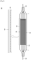
- FIG. 2 is a cross-sectional view illustrating a structure of a secondary battery 100 according to the present invention.
- the secondary battery 100 has a structure in which an electrode assembly 110 is accommodated in a pouch-type battery case 130 and an electrolyte is injected into the battery case 130 so that the electrode assembly 110 is impregnated with the electrolyte.
- the electrode assembly 110 may have various structures, and positive electrodes, separators, and negative electrodes may be stacked in the electrode assembly 110 in various ways. It is possible to apply the present invention to a mono-cell type secondary battery in which one full cell (mono cell) of positive electrode-separator-negative electrode is accommodated in a battery case.
- the electrode assembly 110 may have a stacked structure in which a plurality of unit cells, such as mono cells which are arranged in the order of positive electrode-separator-negative electrode, bi-cells which are arranged in the order of positive electrode-separator-negative electrode-separator-positive electrode, or bi-cells which are arranged in the order of negative electrode-separator-positive electrode-separator-negative electrode, are stacked according to the capacity of the battery.
- a plurality of electrode tabs T protrude from the electrodes of the electrode assembly 110 and the plurality of electrode tabs T are connected to electrode leads 140.
- the electrode leads 140 are a type of terminal which is exposed to the outside and connected to an external device, and a conductive material may be used for the electrode leads 140.
- the electrode leads 140 may include a positive electrode lead and a negative electrode lead.
- the positive electrode lead and the negative electrode lead may be disposed in directions opposite to each other (a so-called bidirectional cell) with respect to a longitudinal direction of the secondary battery 100, or may be disposed in the same direction (a so-called unidirectional cell).
- FIG. 2 illustrates a bidirectional secondary battery 100.
- An electrode assembly 110 of the present invention may be an electrode assembly 110 having a stacked structure as illustrated in FIG. 2 .
- the electrode assembly 110 may be an electrode assembly having a jelly-roll type structure in which long sheet-type positive and negative electrodes are wound with separators interposed therebetween, or an electrode assembly having a stack-folding type structure in which full-cells or bi-cells are wound using a continuous separator sheet having a long length as a mixed type of a jelly-roll type and a stack type.
- the electrode assembly 110 may have a structure in which a separator 113 positioned between a positive electrode 111 and a negative electrode 112 is bonded to an adjacent separator at an outer side thereof, and accordingly, the positive electrode 111 and the negative electrode 112 between the separators may be surrounded by the separator 113 and sealed, and sealing parts 114 and/or 115 may be provided at end parts of the bonded separators.
- a plurality of positive electrodes 111 and a plurality of negative electrodes 112 are alternately disposed, and the separators 113 are individually inserted between the disposed positive electrodes 111 and the disposed negative electrodes 112 and are disposed on an outermost positive electrode and an outermost negative electrode.
- the separators 113 inserted in this way each include a first sealing part 114 that individually seals the positive electrode 111 and the negative electrode 112 by bonding the end parts thereof at the outer side of the electrode assembly 110, and include a second sealing part 115 positioned between an end part of the negative electrode 112 and the first sealing part 114 by bonding the separators 113 disposed on upper and lower surfaces of the negative electrode 112.
- the first sealing part 114 is positioned at an end part of the positive electrode 111 sealed by the separator 113, and the first sealing part 114 and the second sealing part 115 are positioned at the end part of the negative electrode 112.
- the sealing parts 114 and 115 may be formed on outer surfaces of the electrode assembly 110 other than a side surface at the side on which the tab T is formed. Since a side surface of the electrode assembly 110 positioned at the side on which the tab T is formed is a path through which an electrolyte and gas flow, if the side surface is sealed, a basic function of electricity can be degraded.
- the sealing part 114 and/or 115 may have a constant area ratio with respect to a total area of the positive electrode 111 and/or the negative electrode 112 in order to suppress the shrinkage of the separator 113 at a high temperature.
- the first sealing part 114 and/or the second sealing part 115 may have an area ratio of 2% or more with respect to the total area of the positive electrode 111 and/or the negative electrode 112, and more specifically, may have an area ratio of 4% or more, 5% or more, 8% or more, 10% or more, 15% or more, or 20% or more, or may have an area ratio from 5 to 20%, from 5 to 15%, from 5 to 10%, from 10 to 20%, from 11 to 19%, or from 8 to 14%.
- the first sealing part 114 may have an area ratio of 3% with respect to the total area of the negative electrode 112, and the second sealing part 115 may have an area ratio from 5 to 8% with respect to the total area of the negative electrode 112.
- the separator 113 may be firmly fixed around the electrode when exposed to a high temperature while maintaining a high energy density, and thus the shrinkage of the separator 113 can be minimized. That is, it is possible to prevent an effect of suppressing the shrinkage of the separator from being realized due to the significantly low area ratio of the sealing part, or to prevent a decrease in energy density of the electrode assembly due to the excessively high area ratio of the sealing part.
- the separator 113 may have an area large enough to cover surfaces of the positive electrode 111 and the negative electrode 112 and to leave a surplus part of the separator 113 around each electrode.
- the sealing parts 114 and 115 that can fix the separator 113 while sealing the respective electrodes around the positive electrode 111 and the negative electrode 112 may be formed. That is, the sealing parts 114 and 115 may serve to fix the end part of the separator 113 when the secondary battery 100 is exposed to a high temperature, and accordingly, the shrinkage of the separator 113 may be suppressed.
- the secondary battery 100 includes the second sealing part 115 for additionally double sealing the negative electrode 112 to an inside of the first sealing part 114, and thus the shrinkage resistance of the separator 113 at a high temperature may be further improved as compared to the case of including only the first sealing part 114 for individually sealing the positive electrode 111 and the negative electrode 112.
- the separator 113 may form the first sealing part 114 and the second sealing part 115 using an adhesive means applied in the art or by applying heat and fusing when bonding the separators.
- the separator 113 may form the sealing part 114 and/or 115 using a means such as an adhesive or the like containing polyvinylidene fluoride, polyvinyl alcohol, carboxymethyl cellulose (CMC), starch, hydroxypropyl cellulose, regenerated cellulose, polyvinylpyrrolidone, tetrafluoroethylene, polyethylene, polypropylene, ethylene-propylene-diene ether polymer (EPDM), sulfonated EPDM, styrene butadiene rubber (SBR), fluororubber, an acrylic copolymer, or the like.
- a means such as an adhesive or the like containing polyvinylidene fluoride, polyvinyl alcohol, carboxymethyl cellulose (CMC), starch, hydroxypropyl cellulose, regenerated cellulose, polyvinylpyrrolidone, tetrafluoroethylene, polyethylene, polypropylene, ethylene-propylene-diene ether polymer (
- the separator 113 may form the sealing part 114 and/or 115 by pressurizing and thermally fusing the outer side of the separator 113 under a high temperature condition.
- an average thickness of the separators 113 may range from 5 ⁇ m to 50 ⁇ m, and specifically, may range from 10 ⁇ m to 40 ⁇ m, 20 ⁇ m to 30 ⁇ m, or 17 ⁇ m to 28 ⁇ m.
- a total thickness of the electrode assembly 110 can be prevented from becoming excessively thick, and thus the energy density can be further increased.
- the electrode assembly 110 has a configuration including an accommodation part 118 between the first sealing part 114 and the second sealing part 115.
- the accommodation part 118 is formed by bonding the separators 113 disposed on the upper and lower surfaces of the negative electrode 112, and accordingly, may include a certain space in the form of a pouch at the end part of the negative electrode 112.
- a size of the accommodation part 118 is not particularly limited, but when the sealing part is formed by an adhesive means, the thickness of the sealing part may be the same as an average thickness of the negative electrodes.
- the accommodation part 118 may include a fire extinguishing agent that can reduce and/or remove a spark generated inside a secondary battery cell by acting on the spark.
- fire extinguishing agent used for conventional fire suppression may be used as the fire extinguishing agent regardless of whether it is a powder, liquid, or gas, and various types of fire extinguishing agents applied in the art may be used.
- asphyxiation fire extinguishing, cooling fire extinguishing, or fire extinguishing using both of these principles are also applicable.
- the fire extinguishing agent a material in which a main component is a component that is not limited in production and use by the Montreal Protocol and has excellent extinguishing performance may be used, and the material is liquid at room temperature and may be phase-shifted into a gas phase at a specific temperature, for example, 100 to 300 °C, and specifically, at a temperature of 100 to 200 °C.
- Examples of the fire extinguishing agent may include halogenated carbon such as fluorine carbon, fluorine chlorine carbon, fluorine bromine carbon, fluorine iodine carbon, iodofluoro carbon (FIC-217I1 or FIC-13I1), etc., halogenated alkanes such as 2-iodine-1,1,1,2,3,3,3-heptafluoropropane (HFC-227ea), 1,1,1,2,2-pentafluoroethane (CF 3 CF 3 H, HFC-125), 1,1,1,2,3,3,3-heptafluoropropane (CF 3 CHFCF 3 ), chlorotetrafluoroethane (CHClFCF 3 ), 1-chloro-1,2,2,2-tetrafluoroethane (C2HClF4), 2-chloro-1,1,1,2-tetrafluoroethane (CHClFCF 3 , HCFC-124), etc., halogenated keto
- a fire extinguishing agent represented by Chemical Formula C p H q O r X s (where, p, q, r, and s are integers from 0 to 20, and X is at least one of Br, I, and F) may be used, and for example, Novec 1230 of 3M Company may be used.
- the electrode assembly 110 includes a flame propagation prevention part 120 disposed on at least one outer surface thereof.
- the flame propagation prevention part 120 refers to, when one secondary battery ignites, a sheet-shaped member for preventing a flame caused by the ignition from being transmitted to other secondary battery cells.
- the flame propagation prevention part 120 is a sheet-shaped member, a sheet of the fabric concept is densely filled with, for example, crystalline silicate minerals such as mica without including holes like the conventional flame arrester, and thus the flame may be more effectively blocked.
- the flame propagation prevention part 120 of the present invention may increase the rigidity of the secondary battery 100.
- the flame propagation prevention part 120 when the flame propagation prevention part 120 is installed in the electrode assembly, the flame propagation prevention part 120 serves to reduce the pressing width of the battery cell and protect and reinforce the electrode assembly 110 in the battery case 130 in an impact test of the secondary battery 100, as will be described below. Since the flame propagation prevention part 120 of the present invention is installed in the battery case 130, the flame propagation prevention part 120 has stronger rigidity even when a plurality of secondary batteries 100 are installed together, as well as when a single secondary battery 100 is employed as a power source of an electric device, and thus has independent technical meaning.
- a flame propagation prevention sheet 121 performs a function of, for example, when a flame is generated in the secondary battery cell due to overcurrent or thermal runaway, preventing the flame from propagating to other parts in the secondary battery cell or to other adjacent secondary battery cells. Therefore, the flame propagation prevention sheet 121 may be made of one of materials that have both heat resistance and heat insulation to block a flame. Among the materials, the flame propagation prevention sheet 121 included in the flame propagation prevention part 120 of the present invention may be a silicate sheet having both heat resistance and heat insulation properties.
- the silicate sheet referred to in the present invention is made of silicate and performs a function of realizing a flame retardant and/or flame resisting effect within the battery case.
- any silicate commonly used in the art may be applied without particular limitation, and specifically, a material containing one or more of silicon (Si), aluminum (Al), iron (Fe), magnesium (Mg), manganese (Mn), titanium (Ti), sodium (Na), potassium (K), fluorine (F), and oxygen (O) may be used.
- the silicate is a neutral salt in which hydrogen of silicic acid is substituted with another metal atom
- a material in which hydrogen is substituted with an element such as aluminum (Al), iron (Fe), magnesium (Mg), manganese (Mn), titanium (Ti), sodium (Na), potassium (K), etc.
- Al aluminum
- Fe iron
- Mg magnesium
- Mn manganese
- Ti titanium
- Na sodium
- K potassium
- examples of the silicate may include one or more of muscovite, fenzite, celonite, paragonite, margarite, phlogopite, biotite, anite, ferrous mica, siderophilite, clintonite, lithium muscovite, trillithionite, polylithionite, zinnwaldite, and taniolite.
- the flame propagation prevention sheet 121 may include a mica sheet including mica.
- Mica is a coarse material constituting granite, has excellent electrical insulation properties, and has very little change in physical properties when heated. Mica has excellent insulation resistance even at a high temperature of 500 to 1000 °C. Further, mica has excellent flame retardancy, and has a characteristic that it does not generate smoke during burning or heating. Due to these characteristics, by installing the mica sheet including mica in the battery case of the secondary battery, it is possible to prevent or delay thermal runaway within the battery cells, and furthermore, prevent or delay the propagation of thermal runaway between the battery cells.
- the flame propagation prevention sheet 121 may be manufactured in a sheet shape suitable for the size of the electrode assembly by mixing scrap mica or pulverized mica, which is a main component, with a binder (e.g., heat-resistant silicone), forming a large plate, and then cutting the plate to have an appropriate length.
- a binder e.g., heat-resistant silicone
- the method of manufacturing the mica sheet is not limited thereto, and the mica sheet may be manufactured by various methods according to techniques commonly known in the art.
- the expression “consisting of as a main component” may mean that a target component is included in an amount of 60 parts by weight or more, 70 parts by weight or more, 80 parts by weight or more, 85 parts by weight or more, 90 parts by weight or more, 95 parts by weight or more, 98 parts by weight or more, or 99 parts by weight or more with respect to 100 parts by weight of a total amount of the material.
- the flame propagation prevention sheet 121 may contain a binder in an amount of 1 to 20 parts by weight with respect to 100 parts by weight of a total amount of silicate.
- a binder having excellent adhesion to silicate may be used.
- examples of the binder may include one or more of polyethylene (PE), polypropylene (PP), or a polyolefin including a copolymer of PE and PP, a polyamide including nylon, and heat-resistant silicone, but the present invention is not limited thereto.
- the flame propagation prevention part 120 may have a size to almost or completely cover the surface of the electrode assembly 110 in order to prevent flame propagation and protect the electrode assembly 110.
- the flame propagation prevention sheet 121 may have an appropriate thickness in proportion to the thickness of the electrode assembly 110 used. For example, when the electrode assembly 110 having a stacked structure is used, a sheet having a thickness of about 0.1 to 1 mm may be used, but the present invention is not limited thereto. That is, a sheet having a thickness greater or smaller than that of the sheet may be used according to the electrode or battery standard.
- the flame propagation prevention part 120 may be in contact with the electrode assembly to protect the electrode assembly 110 or may be stacked on the electrode assembly with another layer interposed therebetween. As illustrated in FIG. 2 , the flame propagation prevention part 120 may be stacked on both the upper and lower surfaces of the electrode assembly 110 or may be stacked on any one of the upper and lower surfaces of the electrode assembly 110. In some cases, the flame propagation prevention part 120 may also be stacked on both side surfaces of the electrode assembly 110.
- a pouch-type battery case may be used, but the present invention is not limited thereto, and both a cylindrical can-type case and an angular can-type case may be used.
- the pouch-type battery case is made of an aluminum laminate film in which a resin and aluminum are stacked. When the battery (electrode assembly) ignites due to thermal runaway, the aluminum laminate film has a remarkably significantly deteriorated thermal barrier function and melts. Further, when the aluminum laminate film burns, toxic gas is generated and an additional material (battery case) in addition to the electrode assembly is also burned, and thus the burning temperature is also increased.
- the flame propagation prevention part 120 should completely block the propagation of heat or flame during thermal runaway, but it is important to delay the propagation as much as possible even when blocking is impossible.
- the secondary battery module is configured by stacking a plurality of secondary battery cells 100, the flame propagation may be delayed by more than a few minutes in the entire secondary battery module unit when the flame propagation is delayed even for several seconds to several tens of seconds in each secondary battery cell 100.
- the flame propagation delay characteristic is an important characteristic related to ignition, in particular, related to explosion prevention or maximum delay of explosion time.
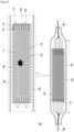
- FIG. 5 is a schematic diagram illustrating a state of flame propagation of an electrode assembly having a stacked structure.
- FIG. 6 is a schematic diagram illustrating a structure of a battery cell according to another embodiment of the present invention for solving the above problems.
- flame propagation prevention parts 120 are stacked between a unit cell (mono cell) M and a unit cell M positioned in the middle of the electrode assembly 110.
- the unit cell has a layer structure of positive electrode-separator 113-negative electrode-separator 113. That is, a predetermined number of unit cells are stacked on an X part, which is an upper part, centering on the flame propagation prevention parts 120, and a predetermined number of unit cells are stacked on a Y part, which is a lower part. For example, when a flame is generated in the X part due to overheating, the flame may propagate to an upper end of the X part.
- the flame propagation prevention parts 120 are positioned between the unit cells of the X part and the Y part, the flame generated in the X part does not propagate to the Y part. Alternatively, even when the flame does propagate, the flame first propagates to the X part, and then the flame propagates to the Y part. In other words, the flame propagation prevention parts 120 serve as a type of barriers, block the flame propagation, and sequentially induce ignition during flame propagation. Accordingly, since the ignition proceeds sequentially even when the ignition proceeds in the Y part, it is possible to prevent the entire electrode assembly from being rapidly ignited and to delay the overall flame propagation time, thereby improving the safety of the battery cell.
- the flame propagation prevention parts 120 may be positioned approximately in the middle part of the stacked unit cells, but the present invention is not limited thereto. As necessary, the flame propagation prevention parts 120 may be disposed between unit cells at a position close to the upper or lower part of the electrode assembly 110.
- the flame propagation prevention parts 120 may suppress the flame propagation to the upper or lower side with respect to the sheet.
- the number of flame propagation prevention parts to be installed is not limited to one. According to the number of stacked unit cells, two or more unit cells may be disposed at an appropriate position of the electrode assembly having a stack structure.
- the upper unit cell, lower unit cell, or upper and lower unit cells with respect to the sheet part cannot perform the charging/discharging function of the battery. Therefore, it is preferable to arrange as few flame propagation prevention parts in the electrode assembly as possible. In other words, it is preferable to determine installation positions and the number of the flame propagation prevention parts within the most suitable range in consideration of battery capacity, safety, and the like.
- the electrode assembly 110 illustrated in FIG. 6 is disposed as a unit cell (mono cell) of which upper and lower parts have a symmetrical structure, and the part of the unit cell that does not contribute to charging and discharging may be minimized by arranging the flame propagation prevention part 120 on a part of a half cell H1 between the symmetrical structures.
- the flame propagation prevention parts 120 of the present embodiment are not positioned only between the unit cells and may be stacked by replacing the separator 113 or the positive or negative electrode which is a part of another unit cell positioned between a specific unit cell M and the unit cell M. In other words, the flame propagation prevention parts may be installed at an appropriate location by comparing the battery capacity and safety. Referring to FIG. 6 , the flame propagation prevention parts 120 are stacked instead of the separator 113 positioned on the negative electrode of the half cell H1.
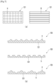
- FIG. 7 illustrates schematic diagrams illustrating a pattern of a flame propagation prevention sheet 121 of the present invention.
- FIG. 7A illustrates a planar shape of the flame propagation prevention sheet 121
- FIG. 7B illustrates a shape of a side surface of the flame propagation prevention sheet 121.
- a flame propagation prevention sheet 121 with a predetermined pattern on a surface thereof may be used. That is, for example, when a mica sheet is used, mica has a property of splitting in a longitudinal direction, and thus protrusions, concave parts, or a pattern of repeating protrusions and concave parts may be formed on the surface to improve the strength of the mica sheet.
- FIG. 7A an example in which a quadrangular shape A is repeated or a stripe shape B is formed in a longitudinal direction of a sheet is illustrated as the shape of such a pattern, but the present invention is not limited thereto.
- a surface area of the flame propagation prevention sheet 121 may increase and thus a heat dissipation area may increase during thermal runaway.
- the pattern is illustrated as being formed only on the upper surface of the flame propagation prevention sheet 121, the pattern may also be formed on each of the upper surface and the lower surface as necessary.
- the secondary battery according to the present invention has the above-described configuration, it is possible to more effectively suppress the shrinkage of the separator when it is exposed to a high temperature, thereby preventing an internal short circuit caused by the shrinkage of the separator and explosion or ignition of the secondary battery. Further, in the secondary battery, since the flame generated during thermal runaway is blocked in a stage in which the electrode assembly is positioned inside the battery cell, a longer flame propagation time may be induced, and thus the safety of the secondary battery and the secondary battery module including the same may be further improved.
- the present invention provides a secondary battery module including the secondary battery of the present invention described above, and a module case in which the secondary battery is accommodated.
- the secondary battery module according to the present invention may be used as a power source for medium-to-large devices that require safety at high temperatures, long cycle characteristics, high rate characteristics, and the like.
- the medium-to-large devices may include power tools powered by an electric motor, electric vehicles including electric vehicles (EVs), hybrid electric vehicles (HEVs), plug-in hybrid electric vehicles (PHEVs), and the like, electric two-wheeled vehicles including electric bicycles (E-bikes) and electric scooters (Escooter), electric golf carts, power storage systems, and the like, and more specifically, may include HEVs, but the present invention is not limited thereto.
- 40 positive electrodes and 40 negative electrodes were prepared, and 120 separators (9.5 cm wide ⁇ 34.5 cm long, and average thickness: about 20 ⁇ m) wider than the positive electrodes and the negative electrodes were prepared. Then, a pouch-type secondary battery cell of 10 cm wide ⁇ 35 cm long ⁇ 1.6 cm thick in which an electrode assembly for a stack, in which 40 unit cells for a stack of separator-negative electrode-separator-positive electrode-separator were stacked, was embedded were manufactured. In this case, as the separators, a separator made of porous polyethylene was used.
- a second sealing part was formed by first thermal fusing an outer side of an end part of the negative electrode for the separators positioned on upper and lower surfaces of the negative electrodes at a temperature of 150 °C, and as shown in Table 1 below, a first sealing part was formed by injecting Novec 1230 (3M Company) serving as a fire extinguishing agent into the separator in which the second sealing part was formed, and thermal fusing an outer side of the electrode assembly.
- Novec 1230 3M Company
- a mica sheet obtained by mixing silicate pulverized powder in which muscovite and lithium muscovite (1 wt./1 wt.) were combined in an amount of 100 parts by weight, and a binder in which polyethylene and polypropylene (1 mol%/mol%) were combined in an amount of 10 parts by weight, processing a mixture to have a sheet shape, and cutting the sheet to the same size as the electrode assembly was used as a flame propagation prevention sheet.
- First sealing part included Second sealing part included Fire extinguishing agent included Position of flame propagation prevention part Example 1 O O - Position 1 Example 2 O O O Position 1 Example 3 O O O Position 2 Comparative Example 1 - - - Position 1 Comparative Example 2 O - - Position 1 Comparative Example 3 O O O Position 3
- Each of the secondary battery cells of the examples and comparative examples was left in an oven heated to 150 °C for 20 seconds. Thereafter, a specimen was recovered and disassembled, changes in horizontal and vertical lengths of separators provided in the electrode assembly after being left in the oven were measured as compared to horizontal and vertical lengths (9.5 cm wide ⁇ 34.5 cm long) before being left in the oven, and an average value thereof was calculated as a shrinkage percentage of the separators. Results of the calculation are shown in Table 2 below.
- the three prepared secondary battery cells were mounted to be stacked in a 3P propagation test device simulated as a cartridge type module.
- the 3P propagation test device was provided to pressurize the secondary battery cells by fastening aluminum plates having a predetermined thickness to the upper and lower parts of the stacked secondary battery cells with bolts assuming a pressurization structure of the secondary battery cells in the module. Further, an aluminum cooling plate was provided between the upper and lower aluminum plates and the secondary battery cell, and between the stacked secondary battery cells.
- a heating pad (silicon heater manufactured by Hakko Co., Ltd., SBH2012) was installed between the lowest secondary battery cell and the aluminum plate, and the secondary battery cell was heated by heating the heating pad at a temperature increase rate of 7 °C/min to induce thermal runaway.
- the secondary battery according to the present invention has excellent safety at a high temperature.
- the separator shrinkage percentage at a high temperature was less than 5%, and it was confirmed that it took 190 seconds or more for all three cells to ignite during the 3P full-wave test. Further, it was found that the secondary batteries of the examples had an average pressing width of less than 8 mm during the impact test and did not cause ignition.
- the secondary battery according to the present invention includes an electrode assembly having a structure in which a separator is individually sealed for a positive electrode and a negative electrode, and includes a flame propagation prevention part on an outer surface of the electrode assembly, and thus it is possible to significantly suppress flame propagation to adjacent battery cells, and it is possible to safely protect the battery cells from external impact by the flame propagation prevention part without a need to thicken the battery case itself even when it is used as a single battery cell. Therefore, it can be seen that overall battery cell safety is significantly improved.
Applications Claiming Priority (2)
| Application Number | Priority Date | Filing Date | Title |
|---|---|---|---|
| KR1020210112116A KR20230030193A (ko) | 2021-08-25 | 2021-08-25 | 이차전지 및 이를 포함하는 이차전지 모듈 |
| PCT/KR2022/095119 WO2023027566A1 (fr) | 2021-08-25 | 2022-08-24 | Batterie secondaire et module de batterie secondaire comprenant celle-ci |
Publications (1)
| Publication Number | Publication Date |
|---|---|
| EP4210138A1 true EP4210138A1 (fr) | 2023-07-12 |
Family
ID=85323357
Family Applications (1)
| Application Number | Title | Priority Date | Filing Date |
|---|---|---|---|
| EP22861774.2A Pending EP4210138A1 (fr) | 2021-08-25 | 2022-08-24 | Batterie secondaire et module de batterie secondaire comprenant celle-ci |
Country Status (6)
| Country | Link |
|---|---|
| US (1) | US20230378566A1 (fr) |
| EP (1) | EP4210138A1 (fr) |
| JP (1) | JP2023543899A (fr) |
| KR (1) | KR20230030193A (fr) |
| CN (1) | CN116368679A (fr) |
| WO (1) | WO2023027566A1 (fr) |
Family Cites Families (7)
| Publication number | Priority date | Publication date | Assignee | Title |
|---|---|---|---|---|
| JP6232849B2 (ja) * | 2012-09-26 | 2017-11-22 | 株式会社Gsユアサ | 蓄電素子 |
| JP6131557B2 (ja) * | 2012-10-05 | 2017-05-24 | 株式会社豊田自動織機 | リチウムイオン二次電池 |
| JP6045921B2 (ja) * | 2013-01-21 | 2016-12-14 | オートモーティブエナジーサプライ株式会社 | 積層型電池とその製造方法 |
| KR101807354B1 (ko) * | 2015-05-12 | 2017-12-08 | 주식회사 엘지화학 | 전극 조립체 |
| JP6600744B2 (ja) * | 2015-11-05 | 2019-10-30 | エルジー・ケム・リミテッド | 電池モジュール |
| KR102282482B1 (ko) | 2018-02-06 | 2021-07-26 | 주식회사 엘지에너지솔루션 | 배터리 모듈 및 이를 포함하는 배터리 팩 |
| KR102452145B1 (ko) | 2020-03-04 | 2022-10-07 | 박상국 | 텐트용 기능성원단 |
-
2021
- 2021-08-25 KR KR1020210112116A patent/KR20230030193A/ko active Search and Examination
-
2022
- 2022-08-24 US US18/031,234 patent/US20230378566A1/en active Pending
- 2022-08-24 CN CN202280006892.9A patent/CN116368679A/zh active Pending
- 2022-08-24 EP EP22861774.2A patent/EP4210138A1/fr active Pending
- 2022-08-24 WO PCT/KR2022/095119 patent/WO2023027566A1/fr unknown
- 2022-08-24 JP JP2023520071A patent/JP2023543899A/ja active Pending
Also Published As
| Publication number | Publication date |
|---|---|
| US20230378566A1 (en) | 2023-11-23 |
| CN116368679A (zh) | 2023-06-30 |
| JP2023543899A (ja) | 2023-10-18 |
| WO2023027566A1 (fr) | 2023-03-02 |
| KR20230030193A (ko) | 2023-03-06 |
Similar Documents
| Publication | Publication Date | Title |
|---|---|---|
| US10381632B2 (en) | Construction of electrochemical storage cell with conductive bridge | |
| US8193770B2 (en) | Battery system for a vehicle having an over-current/over-temperature protective feature | |
| CA2709117C (fr) | Construction d'un accumulateur electrochimique dote d'un bloc conducteur | |
| US8420254B2 (en) | End cover assembly for an electrochemical cell | |
| KR20180088467A (ko) | 리튬 이온 배터리용 로우 프로파일 압력 차단 장치 | |
| US20100255359A1 (en) | Battery pack and battery-equipped device | |
| EP4210138A1 (fr) | Batterie secondaire et module de batterie secondaire comprenant celle-ci | |
| KR20230030195A (ko) | 이차전지 및 이를 포함하는 이차전지 모듈 | |
| KR20230001169A (ko) | 배터리 셀, 상기 배터리 셀을 포함하는 배터리 모듈 및 배터리 팩 | |
| KR20230004030A (ko) | 배터리 셀, 상기 배터리 셀을 포함하는 배터리 모듈 및 배터리 팩 | |
| KR20230004022A (ko) | 배터리 셀, 상기 배터리 셀을 포함하는 배터리 모듈 및 배터리 팩 | |
| KR20230004119A (ko) | 배터리 셀, 이를 포함하는 배터리 모듈 및 배터리 팩 | |
| KR20230007014A (ko) | 안전성이 강화된 리튬 이차전지 모듈 | |
| KR20230063193A (ko) | 스파크 차단 부재를 구비한 이차전지 | |
| KR20240031474A (ko) | 안전성이 향상된 배터리 팩 |
Legal Events
| Date | Code | Title | Description |
|---|---|---|---|
| STAA | Information on the status of an ep patent application or granted ep patent |
Free format text: STATUS: THE INTERNATIONAL PUBLICATION HAS BEEN MADE |
|
| PUAI | Public reference made under article 153(3) epc to a published international application that has entered the european phase |
Free format text: ORIGINAL CODE: 0009012 |
|
| STAA | Information on the status of an ep patent application or granted ep patent |
Free format text: STATUS: REQUEST FOR EXAMINATION WAS MADE |
|
| 17P | Request for examination filed |
Effective date: 20230405 |
|
| AK | Designated contracting states |
Kind code of ref document: A1 Designated state(s): AL AT BE BG CH CY CZ DE DK EE ES FI FR GB GR HR HU IE IS IT LI LT LU LV MC MK MT NL NO PL PT RO RS SE SI SK SM TR |