EP4210027B1 - Orale bionische vorrichtung - Google Patents
Orale bionische vorrichtung Download PDFInfo
- Publication number
- EP4210027B1 EP4210027B1 EP20952151.7A EP20952151A EP4210027B1 EP 4210027 B1 EP4210027 B1 EP 4210027B1 EP 20952151 A EP20952151 A EP 20952151A EP 4210027 B1 EP4210027 B1 EP 4210027B1
- Authority
- EP
- European Patent Office
- Prior art keywords
- assembly
- bionic
- upper jaw
- jaw assembly
- disposed
- Prior art date
- Legal status (The legal status is an assumption and is not a legal conclusion. Google has not performed a legal analysis and makes no representation as to the accuracy of the status listed.)
- Active
Links
Images


Classifications
-
- G—PHYSICS
- G09—EDUCATION; CRYPTOGRAPHY; DISPLAY; ADVERTISING; SEALS
- G09B—EDUCATIONAL OR DEMONSTRATION APPLIANCES; APPLIANCES FOR TEACHING, OR COMMUNICATING WITH, THE BLIND, DEAF OR MUTE; MODELS; PLANETARIA; GLOBES; MAPS; DIAGRAMS
- G09B23/00—Models for scientific, medical, or mathematical purposes, e.g. full-sized devices for demonstration purposes
- G09B23/28—Models for scientific, medical, or mathematical purposes, e.g. full-sized devices for demonstration purposes for medicine
- G09B23/283—Models for scientific, medical, or mathematical purposes, e.g. full-sized devices for demonstration purposes for medicine for dentistry or oral hygiene
Definitions
- CN 111 175 191 A depicts a biomimetic chewing device designed to simulate the oral cavity for testing the rheological properties of food, capturing more accurate mouthfeel data. It features bionic teeth, a tongue, and hydraulic mechanisms to mimic chewing, enhancing evaluation of food texture and processing.
- a technical problem to be resolved by the present invention is to provide a bionic oral cavity device.
- the present invention provides a bionic oral cavity device, comprising: a bionic lower jaw assembly, a bionic upper jaw movement assembly disposed on an upper side of the lower jaw assembly, a bionic cheeks movement assembly disposed on left and right sides of the lower jaw assembly, a bionic tongue movement assembly disposed on a lower side of the lower jaw assembly, a feeding movement assembly disposed on a front side of the lower jaw assembly, a blockage assembly disposed on a rear side of the lower jaw assembly, and a saliva injection assembly.
- the bionic upper jaw movement assembly comprises an upper jaw assembly and a first crank slider mechanism controlling the upper jaw assembly to move vertically
- the first crank slider mechanism comprises a first eccentric wheel, a first motor driving the first eccentric wheel to rotate, a first connecting rod, and a first sliding rod, an upper end of the first connecting rod is rotatably connected to the first eccentric wheel, a lower end of the first connecting rod is rotatably connected to an upper end of the first sliding rod
- the bionic upper jaw movement assembly further comprises a first fixing plate, the first sliding rod is vertically slidably mounted on the first fixing plate, a lower end of the first sliding rod is capable of driving the upper jaw assembly to move vertically
- the bionic upper jaw movement assembly further comprises a first sensing sheet mounted on the first eccentric wheel and a first sensor corresponding to the first sensing sheet; every time when the first eccentric wheel rotates one circle, the first sensing sheet passes through the first sensor once, and when the first sensor senses the first sensing sheet, a pause signal is capable of being sent to a
- a pressure sensor is further disposed between the lower end of the first sliding rod and the upper jaw assembly, a slider is further disposed on the upper jaw assembly, the slider is transversely slidably connected to an upper side of the upper jaw assembly, and the lower end of the first sliding rod is fixedly connected to the slider.
- the upper jaw assembly comprises an upper jaw body and an upper cover disposed on the upper jaw body, the upper jaw body has a cavity with an opening facing upward, an elastic sealing member is disposed at the opening of the cavity, the upper cover covers the opening of the cavity, the elastic sealing member produces a sealing effect, and two circulating water ports allowing communication between the cavity and external circulating water are further provided on the upper jaw body.
- Upper teeth are mounted under the upper jaw body, the lower jaw assembly comprises a bottom wall, two transversely disposed sidewalls, and a rear wall located behind the two sidewalls, a discharge port is provided in the rear wall, the blockage assembly comprises a blockage sheet blocking the discharge port, a fifth motor driving the blockage sheet to move longitudinally, during a mastication in the oral cavity, the blockage sheet is capable of blocking the discharge port;
- two rows of lower teeth corresponding to the upper teeth are provided on the bottom wall
- the upper jaw assembly is capable of being driven by the first crank slider mechanism to be inserted into the lower jaw assembly, to make the upper teeth and the lower teeth contact and press against each other, a cheeks film is disposed on the two sidewalls of the lower jaw assembly, a tongue film is provided on the bottom wall, and the cheeks film and the tongue film are transparent elastic films.
- the feeding movement assembly comprises a feeding channel, the feeding channel is in communication with the front side of the lower jaw assembly, a feeding jacking block is disposed in the feeding channel, the feeding jacking block is used to push food in the feeding channel to the lower jaw assembly, the feeding movement assembly further comprises a drive assembly used to drive the feeding jacking block to move, the drive assembly comprises a rack and a pushing rod that are connected to the feeding jacking block, the rack and the pushing rod are disposed in parallel to each other, the drive assembly further comprises a fourth motor and a gear driven by the fourth motor, the gear is engaged with the rack, the feeding movement assembly further comprises a vertically disposed fourth fixing plate, the rack and the pushing rod slidably pass through the fourth fixing plate, and the distal ends of the rack and the pushing rod are fixedly connected by a connecting block.
- the saliva injection assembly comprises an injection cylinder, a water bath pot in communication with the injection cylinder, and a heating coil, the water bath pot is in communication with the upper jaw assembly to form water circulation, and the heating coil heats a liquid in the water bath pot.
- a first protruding portion is disposed on either a left side or a right side of the upper jaw body, a second protruding portion matching the first protruding portion is disposed on one sidewall of the lower jaw assembly, an elastic member is disposed on the other sidewall of the lower jaw assembly, the elastic member is capable of applying a pushing force to the upper jaw assembly, and as the upper jaw assembly moves downward, the second protruding portion is capable of pressing the first protruding portion, to enable the upper jaw assembly to overcome the pushing force of the elastic member to move toward a side close to the elastic member.
- the bionic cheeks movement assembly comprises a second crank slider mechanism and a bionic cheeks jacking block driven by the second crank slider mechanism
- the second crank slider mechanism comprises a second eccentric wheel, a second motor driving the second eccentric wheel to rotate, a second connecting rod, and a second sliding rod
- one end of the second connecting rod is rotatably connected to the second eccentric wheel
- the other end of the second connecting rod is rotatably connected to an end of the second sliding rod
- the bionic cheeks movement assembly further comprises a second fixing plate
- the second sliding rod is transversely slidably mounted on the second fixing plate, and an end portion of the second sliding rod is capable of driving the bionic cheeks jacking block to push the cheeks film.
- the bionic tongue movement assembly comprises a third crank slider mechanism and a bionic tongue jacking block driven by the third crank slider mechanism
- the third crank slider mechanism comprises a third eccentric wheel, a third motor driving the third eccentric wheel to rotate, a third connecting rod, and a third sliding rod
- one end of the third connecting rod is rotatably connected to the third eccentric wheel
- the other end of the third connecting rod is rotatably connected to one end of the third sliding rod
- the bionic tongue movement assembly further comprises a third fixing plate
- the third sliding rod is vertically slidably mounted on the third fixing plate
- an end portion of the third sliding rod is capable of driving the bionic tongue jacking block to push the tongue film.
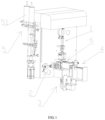
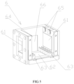
- bionic upper jaw movement assembly 2. bionic cheeks movement assembly; 3. bionic tongue movement assembly; 4. feeding movement assembly; 5. saliva injection assembly; 6. lower jaw assembly; and 7. blockage assembly;
- FIG. 1 shows a bionic oral cavity device in the present application, comprising: a bionic lower jaw assembly 6, a bionic upper jaw movement assembly 1 disposed at an upper side of the lower jaw assembly 6, a bionic cheeks movement assembly 2 disposed on left and right sides of the lower jaw assembly 6, a bionic tongue movement assembly disposed on a lower side of the lower jaw assembly 6, a feeding movement assembly 4 disposed on a front side of the lower jaw assembly 6, a blockage assembly 7 disposed on a rear side of the lower jaw assembly 6, and a saliva injection assembly 5.
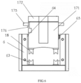
- a lower end of the first sliding rod 14 is capable of driving the upper jaw assembly 17 to move vertically.
- the bionic upper jaw movement assembly 1 further comprises a first sensing sheet 110 mounted on the first eccentric wheel 11 and a first sensor 111 corresponding to the first sensing sheet 110. Every time when the first eccentric wheel 11 rotates one circle, the first sensing sheet 110 passes through the first sensor 111 once. When the first sensor 111 senses the first sensing sheet 110, a control signal is sent to a first drive motor, and the first drive motor is controlled to pause a while to simulate the rhythm of mastication in the oral cavity.
- a pressure sensor 15 is further disposed between the lower end of the first sliding rod 14 and the upper jaw assembly 17.
- Upper teeth 18 are mounted on the bottom of the upper jaw body 171.
- two longitudinally extending mounting grooves for the upper teeth 18 are provided on a lower side of the upper jaw body 171.
- Longitudinally extending clamping edges are disposed on left and right sides of the mounting grooves for the upper teeth 18.
- Clamping grooves matching the clamping edges are provided on the upper teeth 18.
- the upper teeth 18 are detachably mounted in the mounting grooves for the upper teeth 18 through the clamping grooves. In this assembly manner, the upper teeth 18 may be removed, making assembly and disassembly convenient, thereby facilitating cleaning of the upper jaw.
- a first through hole 177 and a second through hole 178 are further provided in the upper jaw body 171.
- the first through hole 177 is used for injecting saliva into the oral cavity
- the second through hole 178 is used for detecting the smell in the oral cavity.
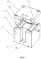
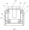
- FIG. 5 shows the lower jaw assembly 6 in the present application.
- the lower jaw assembly 6 comprises a bottom wall, two sidewalls located on the left and right, and a rear wall located behind the two sidewalls. Two rows of lower teeth 63 corresponding to the upper teeth 18 are provided on the bottom wall.
- the upper jaw assembly 17 is capable of being driven by the first crank slider mechanism 16 to be inserted into the lower jaw assembly 6, so that the upper teeth 18 and the lower teeth 63 contact and press against each other.
- a cheeks film 61 is disposed on the two sidewalls of the lower jaw assembly 6.
- a tongue film 62 is provided on the bottom wall.
- a discharge port 66 is provided in the rear wall of the lower jaw assembly 6.
- the cheeks film 61 and the tongue film 62 are made of a transparent elastic material, so that it is convenient for an experimenter to observe a process that food breaks down inside the oral cavity.
- An inner surface of the cheeks film 61 is attached to inner surfaces of the two sidewalls of the lower jaw assembly to form a smooth surface.
- Inner surfaces of the tongue film 62 and the bottom wall of the lower jaw assembly are attached to form a smooth surface.
- both the two sidewalls and the bottom wall have smooth surfaces, thereby further facilitating cleaning.
- a first protruding portion 176 is disposed on one of a left side and a right side of the upper jaw body 171.
- a second protruding portion 64 matching the first protruding portion 176 is disposed on one sidewall of the lower jaw assembly 6.
- An elastic member 65 is disposed on the other sidewall of the lower jaw assembly 6. The elastic member 65 is capable of applying a pushing force to the upper jaw assembly 17. As the upper jaw assembly 17 moves downward, the second protruding portion 64 is capable of pressing the first protruding portion 176, to enable the upper jaw assembly 17 to overcome the pushing force of the elastic member 65 to move toward a side close to the elastic member 65.
- the first protruding portion 176 is a strip-shaped flange with an upper side surface and a lower side surface being wedge-shaped surfaces
- the second protruding portion 64 is a strip-shaped flange with an arc-shaped cross-section.
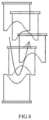
- the upper jaw assembly 17 moves toward a side away from the elastic member 65, so that the upper jaw assembly 17 sways transversely while moving vertically.
- the movement between the upper teeth 18 and the lower teeth 63 presents an elliptical form.
- the upper teeth 18 and the lower teeth 63 transversely rub against each other to break down food, thereby simulating a process of crushing and grinding food in the oral cavity.
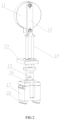
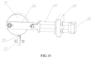
- FIG. 10 shows the bionic cheeks movement assembly 2 in the present application.
- the bionic cheeks movement assembly 2 comprises a second crank slider mechanism 16 and a bionic cheeks jacking block 25 driven by the second crank slider mechanism 16.
- the second crank slider mechanism 16 comprises a second eccentric wheel 21, a second motor for driving the second eccentric wheel 21 to rotate, a second connecting rod 22, and a second sliding rod 23.
- One end of the second connecting rod 22 is rotatably connected to the second eccentric wheel 21.
- the other end of the second connecting rod 22 is rotatably connected to an end of the second sliding rod 23.
- the bionic cheeks movement assembly 2 further comprises a second fixing plate.
- the second sliding rod 23 is transversely slidably mounted on the second fixing plate. An end portion of the second sliding rod 23 is capable of driving the bionic cheeks jacking block 25 to push the cheeks film 61.
- the bionic cheeks movement assembly 2 further comprises a second sensing sheet 26 mounted on the second eccentric wheel 21 and a second sensor 27 corresponding to the second sensing sheet 26. Every time when the second eccentric wheel 21 rotates one circle, the second sensing sheet 26 passes through the second sensor 27 once. When the second sensor 27 senses the second sensing sheet 26, a control signal is sent to a second drive motor, and the second drive motor is controlled to pause a while to simulate the movement pattern of the cheeks during mastication in the oral cavity.
- FIG. 9 shows the bionic tongue movement assembly 3 in the present application.
- the bionic tongue movement assembly 3 comprises a third crank slider mechanism 16 and a bionic tongue jacking block 37 driven by the third crank slider mechanism 16.
- the third crank slider mechanism 16 comprises a third eccentric wheel 32, a third motor 31 for driving the third eccentric wheel 32 to rotate, a third connecting rod 33, and a third sliding rod 34.
- One end of the third connecting rod 33 is rotatably connected to the third eccentric wheel 32.
- the other end of the third connecting rod 33 is rotatably connected to one end of the third sliding rod 34.
- the bionic tongue movement assembly further comprises a third fixing plate 35.
- the third sliding rod 34 is vertically slidably mounted on the third fixing plate 35. An end portion of the third sliding rod 34 is capable of driving the bionic tongue jacking block 37 to push the tongue film.
- the bionic tongue movement assembly further comprises a third sensing sheet 39 mounted on the third eccentric wheel 32 and a third sensor 38 corresponding to the third sensing sheet 39. Every time when the third eccentric wheel 32 rotates one circle, the third sensing sheet 39 passes through the third sensor 38 once. When the third sensor 38 senses the third sensing sheet 39, a control signal is sent to a third drive motor, and the third drive motor is controlled to pause a while to simulate the movement pattern of the tongue during mastication in the oral cavity.
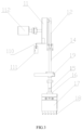
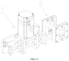
- FIG. 11 shows the feeding movement assembly 4 in the present application.
- the feeding movement assembly 4 comprises a feeding channel 41.
- the feeding channel 41 is in communication with the front side of the lower jaw assembly 6.
- a feeding jacking block 42 is disposed in the feeding channel 41.
- the feeding jacking block 42 is used to push food in the feeding channel 41 to the lower jaw assembly 6.
- the feeding movement assembly 4 further comprises a drive assembly for driving the feeding jacking block 42 to move.
- the feeding movement assembly 4 further comprises a vertically disposed fourth fixing plate 48.
- the rack 43 and the pushing rod 44 slidably pass through the fourth fixing plate 48.
- the distal ends of the rack 43 and the pushing rod 44 are fixedly connected by a connecting block 45.
Landscapes
- Engineering & Computer Science (AREA)
- General Physics & Mathematics (AREA)
- Health & Medical Sciences (AREA)
- Physics & Mathematics (AREA)
- Algebra (AREA)
- Mathematical Analysis (AREA)
- General Health & Medical Sciences (AREA)
- Medical Informatics (AREA)
- Medicinal Chemistry (AREA)
- Public Health (AREA)
- Oral & Maxillofacial Surgery (AREA)
- Computational Mathematics (AREA)
- Epidemiology (AREA)
- Chemical & Material Sciences (AREA)
- Mathematical Optimization (AREA)
- Mathematical Physics (AREA)
- Pure & Applied Mathematics (AREA)
- Business, Economics & Management (AREA)
- Educational Administration (AREA)
- Educational Technology (AREA)
- Theoretical Computer Science (AREA)
- Dental Tools And Instruments Or Auxiliary Dental Instruments (AREA)
Claims (5)
- Bionische Mundhöhlenvorrichtung, umfassend: eine bionische Unterkiefereinheit (6), eine an einer oberen Seite der Unterkiefereinheit (6) angeordnete bionische Oberkieferbewegungseinheit (1), eine an den linken und rechten Seiten der Unterkiefereinheit (6) angeordnete bionische Wangenbewegungseinheit (2), eine an einer unteren Seite der Unterkiefereinheit (6) angeordnete bionische Zungenbewegungseinheit (3), eine an einer Vorderseite der Unterkiefereinheit (6) angeordnete Zuführbewegungseinheit (4), eine an einer Rückseite der Unterkiefereinheit (6) angeordnete Blockierungseinheit (7), und eine Speichelinjektionseinheit (5);wobei die bionische Oberkieferbewegungseinheit (1) eine Oberkiefereinheit (17) und einen ersten Kurbelgleitmechanismus umfasst, der die Oberkiefereinheit (17) steuert, um sich vertikal zu bewegen, wobei der erste Kurbelgleitmechanismus ein erstes exzentrisches Rad (11), einen ersten Motor (112), der das erste exzentrische Rad (11) zum Rotieren antreibt, eine erste Verbindungsstange (12) und eine erste Gleitstange (14) umfasst, wobei ein oberes Ende der ersten Verbindungsstange (12) drehbar mit dem ersten exzentrischen Rad (11) verbunden ist, ein unteres Ende der ersten Verbindungsstange (12) drehbar mit einem oberen Ende der ersten Gleitstange (14) verbunden ist, die bionische Oberkieferbewegungseinheit (1) weiterhin eine erste Fixierplatte (19) umfasst, wobei die erste Gleitstange (14) vertikal gleitend an der ersten Fixierplatte (19) montiert ist, ein unteres Ende der ersten Gleitstange (14) in der Lage ist, die Oberkiefereinheit (17) anzutreiben, um sich vertikal zu bewegen, die bionische Oberkieferbewegungseinheit (1) weiterhin eine erste Sensorfolie (110) umfasst, die am ersten exzentrischen Rad (11) montiert ist, und einen ersten Sensor (111), der der ersten Sensorfolie (110) entspricht, wodurch bei jeder vollständigen Umdrehung des ersten exzentrischen Rades (11) die erste Sensorfolie (110) den ersten Sensor (111) einmal passiert, und wenn der erste Sensor (111) die erste Sensorfolie (110) erfasst, ein Pausensignal an den ersten Motor gesendet ist, wodurch der erste Motor gesteuert ist, um zu pausieren;wobei ein Drucksensor (15) ferner zwischen dem unteren Ende der ersten Gleitstange (14) und der Oberkiefereinheit (17) angeordnet ist, ein Schieber (16) ferner auf der Oberkiefereinheit (17) angeordnet ist, der Schieber (16) quer gleitend mit einer Oberseite der Oberkiefereinheit (17) verbunden ist und das untere Ende der ersten Gleitstange (14) fest mit dem Schieber (16) verbunden ist;wobei die Oberkiefereinheit (17) einen Oberkieferkörper (171) und eine auf dem Oberkieferkörper (171) angeordnete obere Abdeckung (172) umfasst, der Oberkieferkörper (171) eine Kavität (174) mit einer nach oben gerichteten Öffnung aufweist, ein elastisches Dichtungselement (173) an der Öffnung der Kavität (174) angeordnet ist, die obere Abdeckung (172) die Öffnung der Kavität (174) abdeckt, das elastische Dichtungselement (173) eine Dichtungswirkung erzeugt und zwei Umwälzwasseranschlüsse (175), die eine Verbindung zwischen der Kavität (174) und externem Umwälzwasser ermöglichen, ferner am Oberkieferkörper (171) vorgesehen sind;wobei obere Zähne (18) unter dem Oberkieferkörper (171) montiert sind; wobei die Unterkiefereinheit (6) eine Bodenwand, zwei quer angeordnete Seitenwände und eine hinter den zwei Seitenwänden befindliche Rückwand umfasst, wobei in der Rückwand eine Auslassöffnung (66) vorgesehen ist; wobei die Blockierungseinheit (7) eine Blockierungsplatte, welche die Auslassöffnung (66) blockiert, sowie einen fünften Motor umfasst, der die Blockierungsplatte antreibt, um sich in Längsrichtung zu bewegen; während eines Kauvorgangs in der Kavität die Blockierungsplatte in der Lage ist, die Auslassöffnung (66) zu blockieren; wobei zwei Reihen unterer Zähne (63), die den oberen Zähnen (18) entsprechen, auf der Bodenwand vorgesehen sind, die Oberkiefereinheit (17) durch den ersten Kurbelgleitmechanismus angetrieben werden kann, um in die Unterkiefereinheit (6) eingeführt zu werden, sodass die oberen Zähne (18) und die unteren Zähne (63) miteinander in Kontakt kommen und gegeneinander drücken; wobei eine Wangenmembran (61) an den zwei Seitenwänden der Unterkiefereinheit (6) angeordnet ist, eine Zungenmembran (62) auf der Bodenwand vorgesehen ist, und die Wangenmembran (61) und die Zungenmembran (62) transparente elastische Membranen sind; undwobei die Zuführbewegungseinheit (4) einen Zuführkanal (41) umfasst, wobei der Zuführkanal (41) mit der Vorderseite der Unterkiefereinheit (6) in Verbindung steht, wobei ein Zuführhebeblock (42) im Zuführkanal (41) angeordnet ist, der Nahrung im Zuführkanal (41) zur Unterkiefereinheit (6) schiebt, wobei die Zuführbewegungseinheit (4) weiterhin eine Antriebsanordnung zum Antreiben des Zuführhebeblocks (42) zur Bewegung umfasst, wobei die Antriebsanordnung eine Zahnstange (43) und eine Druckstange (44) umfasst, die mit dem Zuführhebeblock (42) verbunden sind, wobei die Zahnstange (43) und die Druckstange (44) parallel zueinander angeordnet sind, wobei die Antriebsanordnung weiterhin einen vierten Motor (47) und ein vom vierten Motor (47) angetriebenes Zahnrad (46) umfasst, wobei das Zahnrad (46) mit der Zahnstange (43) im Eingriff steht, wobei die Zuführbewegungseinheit (4) weiterhin eine vertikal angeordnete vierte Fixierplatte (48) umfasst, wobei die Zahnstange (43) und die Druckstange (44) gleitend durch die vierte Fixierplatte (48) hindurchgehen und distale Enden der Zahnstange (43) und der Druckstange (44) durch einen Verbindungsblock (45) fest verbunden sind.
- Bionische Mundhöhlenvorrichtung nach Anspruch 1, wobei ein erstes Vorsprungsteil (176) entweder auf einer linken Seite oder einer rechten Seite des Oberkieferkörpers (171) angeordnet ist, ein zweites Vorsprungsteil (64), das dem ersten Vorsprungsteil (176) entspricht, auf einer Seitenwand der Unterkiefereinheit (6) angeordnet ist, ein elastisches Element (65) auf der anderen Seitenwand der Unterkiefereinheit (6) angeordnet ist, wobei das elastische Element (65) in der Lage ist, eine Schubkraft auf die Oberkiefereinheit (17) auszuüben, und wenn sich die Oberkiefereinheit (17) nach unten bewegt, das zweite Vorsprungsteil (64) in der Lage ist, das erste Vorsprungsteil (176) zu drücken, um der Oberkiefereinheit (17) zu ermöglichen, die Schubkraft des elastischen Elements (65) zu überwinden, um sich in Richtung einer Seite nahe dem elastischen Element (65) zu bewegen.
- Bionische Mundhöhlenvorrichtung nach Anspruch 1, wobei die bionische Wangenbewegungseinheit (2) einen zweiten Kurbelgleitmechanismus und einen bionischen Wangenhebeblock (25) umfasst, der durch den zweiten Kurbelgleitmechanismus angetrieben ist, wobei der zweite Kurbelgleitmechanismus ein zweites exzentrisches Rad (21), einen zweiten Motor, der das zweite exzentrische Rad (21) zum Rotieren antreibt, eine zweite Verbindungsstange (22) und eine zweite Gleitstange (23) umfasst, wobei ein Ende der zweiten Verbindungsstange (22) drehbar mit dem zweiten exzentrischen Rad (21) verbunden ist, ein anderes Ende der zweiten Verbindungsstange (22) drehbar mit einem Ende der zweiten Gleitstange (23) verbunden ist, die bionische Wangenbewegungseinheit (2) weiterhin eine zweite Fixierplatte umfasst, wobei die zweite Gleitstange (23) quer gleitend auf der zweiten Fixierplatte montiert ist, und ein Endabschnitt der zweiten Gleitstange (23) in der Lage ist, den bionischen Wangenhebeblock (25) anzutreiben, um die Wangenmembran (61) zu drücken.
- Bionische Mundhöhlenvorrichtung nach Anspruch 1, wobei die bionische Zungenbewegungseinheit (3) einen dritten Kurbelgleitmechanismus und einen bionischen Zungenfixierungsblock (37) umfasst, der durch den dritten Kurbelgleitmechanismus angetrieben ist, wobei der dritte Kurbelgleitmechanismus ein drittes exzentrisches Rad (32), einen dritten Motor (31), der das dritte exzentrische Rad (32) zur Rotation antreibt, eine dritte Verbindungsstange (33) und eine dritte Gleitstange (34) umfasst, wobei ein Ende der dritten Verbindungsstange (33) drehbar mit dem dritten exzentrischen Rad (32) verbunden ist, ein anderes Ende der dritten Verbindungsstange (33) drehbar mit einem Ende der dritten Gleitstange (34) verbunden ist, wobei die bionische Zungenbewegungseinheit (3) weiterhin eine dritte Fixierplatte (35) umfasst, wobei die dritte Gleitstange (34) vertikal gleitend an der dritten Fixierplatte (35) montiert ist und ein Endabschnitt der dritten Gleitstange (34) in der Lage ist, den bionischen Zungenfixierungsblock (37) anzutreiben, um die Zungenmembran (62) zu drücken.
- Bionische Mundhöhlenvorrichtung nach Anspruch 1, wobei die Speichelinjektionseinheit (5) einen Injektionszylinder (51), einen mit dem Injektionszylinder (51) in Verbindung stehenden Wasserbadtopf (52) und eine Heizspule (53) umfasst, wobei der Wasserbadtopf (52) mit der Oberkiefereinheit (17) zur Bildung eines Wasserkreislaufs in Verbindung steht, und die Heizspule (53) eine Flüssigkeit im Wasserbadtopf (52) erhitzt.
Applications Claiming Priority (2)
| Application Number | Priority Date | Filing Date | Title |
|---|---|---|---|
| CN202010906266.8A CN111968472B (zh) | 2020-09-01 | 2020-09-01 | 一种仿生口腔设备 |
| PCT/CN2020/122320 WO2022047909A1 (zh) | 2020-09-01 | 2020-10-21 | 一种仿生口腔设备 |
Publications (4)
| Publication Number | Publication Date |
|---|---|
| EP4210027A1 EP4210027A1 (de) | 2023-07-12 |
| EP4210027A4 EP4210027A4 (de) | 2024-09-11 |
| EP4210027C0 EP4210027C0 (de) | 2025-07-09 |
| EP4210027B1 true EP4210027B1 (de) | 2025-07-09 |
Family
ID=73391632
Family Applications (1)
| Application Number | Title | Priority Date | Filing Date |
|---|---|---|---|
| EP20952151.7A Active EP4210027B1 (de) | 2020-09-01 | 2020-10-21 | Orale bionische vorrichtung |
Country Status (3)
| Country | Link |
|---|---|
| EP (1) | EP4210027B1 (de) |
| CN (1) | CN111968472B (de) |
| WO (1) | WO2022047909A1 (de) |
Families Citing this family (2)
| Publication number | Priority date | Publication date | Assignee | Title |
|---|---|---|---|---|
| CN112614410A (zh) * | 2020-12-24 | 2021-04-06 | 中国检验检疫科学研究院 | 模拟人体口腔运动的仿生装置及其控制方法 |
| CN115588346A (zh) * | 2022-09-28 | 2023-01-10 | 晓东宜健(苏州)仪器设备有限公司 | 一种人工口腔系统 |
Citations (1)
| Publication number | Priority date | Publication date | Assignee | Title |
|---|---|---|---|---|
| US20190096288A1 (en) * | 2017-07-03 | 2019-03-28 | Jiangnan University | Food Swallowing Simulating Device |
Family Cites Families (17)
| Publication number | Priority date | Publication date | Assignee | Title |
|---|---|---|---|---|
| FR3007181B1 (fr) * | 2013-06-13 | 2016-11-11 | Ecole Nat Veterinaire Agroalimentaire Et De L'alimentation Nantes-Atlantique | Bouche artificielle pour l’etude des phenomenes-physico-chimiques et/ou biologiques lors de la mastication et procede d’analyse des fractions liquides et volatiles, mettant en oeuvre une telle bouche artificielle |
| CN103558104A (zh) * | 2013-11-13 | 2014-02-05 | 长江师范学院 | 基于耦合仿生的食品脆性测试仪及测试方法 |
| US10582995B2 (en) * | 2014-02-27 | 2020-03-10 | University of Pittsburgh—of the Commonwealth System of Higher Education | Intra-oral prostheses and other anatomical prostheses |
| CN106239480A (zh) * | 2016-08-26 | 2016-12-21 | 电子科技大学 | 一种基于气动人工肌肉的下颌咀嚼机器人 |
| CN206259103U (zh) * | 2016-11-02 | 2017-06-16 | 漳州卫生职业学院 | 手柄式可控开合的口腔护理模型 |
| CN107063904B (zh) * | 2017-03-22 | 2019-08-20 | 吉林大学 | 一种仿咀嚼设备 |
| CN108682252B (zh) * | 2018-06-11 | 2020-07-03 | 江南大学 | 一种基于连杆运动的食物吞咽模拟装置 |
| CN209764691U (zh) * | 2019-03-12 | 2019-12-10 | 江南大学 | 一种咀嚼仿生装置 |
| CN110349488B (zh) * | 2019-07-26 | 2024-05-10 | 中南大学湘雅医院 | 一种可模拟多种状态的人体喉咽疾病诊疗装置 |
| CN110883766B (zh) * | 2019-12-04 | 2021-08-10 | 大连理工大学 | 一种咀嚼肌群和颞下颌关节双仿生的咀嚼机器人 |
| CN110849651B (zh) * | 2019-12-04 | 2021-01-05 | 大连理工大学 | 一种用于义齿性能测试的仿生咀嚼机器人及使用方法 |
| CN111175191B (zh) * | 2020-03-26 | 2022-01-25 | 江南大学 | 一种用于食品流变性检测的仿生咀嚼装置 |
| CN213121854U (zh) * | 2020-09-01 | 2021-05-04 | 晓东宜健(苏州)仪器设备有限公司 | 一种仿上颚运动组件及仿生口腔设备 |
| CN212694671U (zh) * | 2020-09-01 | 2021-03-12 | 晓东宜健(苏州)仪器设备有限公司 | 一种仿生口腔设备 |
| CN213123493U (zh) * | 2020-09-01 | 2021-05-04 | 晓东宜健(苏州)仪器设备有限公司 | 一种仿双颊运动组件及仿生口腔设备 |
| CN213123494U (zh) * | 2020-09-01 | 2021-05-04 | 晓东宜健(苏州)仪器设备有限公司 | 一种仿舌部运动组件及仿生口腔设备 |
| CN112014532B (zh) * | 2020-09-01 | 2025-06-13 | 晓东宜健(苏州)仪器设备有限公司 | 一种仿上颚运动组件及仿生口腔设备 |
-
2020
- 2020-09-01 CN CN202010906266.8A patent/CN111968472B/zh active Active
- 2020-10-21 WO PCT/CN2020/122320 patent/WO2022047909A1/zh not_active Ceased
- 2020-10-21 EP EP20952151.7A patent/EP4210027B1/de active Active
Patent Citations (1)
| Publication number | Priority date | Publication date | Assignee | Title |
|---|---|---|---|---|
| US20190096288A1 (en) * | 2017-07-03 | 2019-03-28 | Jiangnan University | Food Swallowing Simulating Device |
Also Published As
| Publication number | Publication date |
|---|---|
| EP4210027A4 (de) | 2024-09-11 |
| CN111968472B (zh) | 2025-01-28 |
| EP4210027C0 (de) | 2025-07-09 |
| CN111968472A (zh) | 2020-11-20 |
| EP4210027A1 (de) | 2023-07-12 |
| WO2022047909A1 (zh) | 2022-03-10 |
Similar Documents
| Publication | Publication Date | Title |
|---|---|---|
| EP4210027B1 (de) | Orale bionische vorrichtung | |
| JP5406193B2 (ja) | 哺乳動物の咀嚼動作を擬態する装置 | |
| HRP20250150T1 (hr) | Medicinski sustav i postupak za njegovu proizvodnju | |
| CN109009177B (zh) | 一种基于薄膜压力传感器的单颗牙咬合力测量装置 | |
| CN212694671U (zh) | 一种仿生口腔设备 | |
| CN213123493U (zh) | 一种仿双颊运动组件及仿生口腔设备 | |
| CN213121854U (zh) | 一种仿上颚运动组件及仿生口腔设备 | |
| CN112014532B (zh) | 一种仿上颚运动组件及仿生口腔设备 | |
| JP7649511B2 (ja) | 食塊形成装置、咀嚼状態評価方法、食感評価方法及び食塊の製造方法 | |
| CN213123494U (zh) | 一种仿舌部运动组件及仿生口腔设备 | |
| CN110652309B (zh) | 基于柔性材料的牙齿咬合力测量装置 | |
| US20230408391A1 (en) | Chewing machine | |
| JP2010183886A (ja) | ガムベースの設計方法 | |
| Smith et al. | Design and development of a robotic bioreactor for in vitro tissue engineering | |
| CN114935634A (zh) | 一种体外模拟咀嚼运动控制装置及其方法 | |
| CN103471944A (zh) | 口腔修复体疲劳试验机 | |
| CN210893978U (zh) | 一种用于测试的仿生口腔结构 | |
| CN103226911A (zh) | 一种用于口腔修复材料耐磨性测试的模拟刷牙装置 | |
| CN203768361U (zh) | 组织工程心肌细胞搏动压检测装置 | |
| Jiang et al. | Bio-inspired breastfeeding simulator integrated with software interface and feedback controls | |
| CN223624102U (zh) | 一种面膜贴敷性测试装置 | |
| CN213635022U (zh) | 一种仿下颌咬合运动的装置 | |
| CN108272476B (zh) | 一种口腔科用舌苔采集器 | |
| TW202135680A (zh) | 食團形成裝置、食團的形成方法 | |
| CN216738329U (zh) | 一种便于加药的生物培养瓶 |
Legal Events
| Date | Code | Title | Description |
|---|---|---|---|
| STAA | Information on the status of an ep patent application or granted ep patent |
Free format text: STATUS: THE INTERNATIONAL PUBLICATION HAS BEEN MADE |
|
| PUAI | Public reference made under article 153(3) epc to a published international application that has entered the european phase |
Free format text: ORIGINAL CODE: 0009012 |
|
| STAA | Information on the status of an ep patent application or granted ep patent |
Free format text: STATUS: REQUEST FOR EXAMINATION WAS MADE |
|
| 17P | Request for examination filed |
Effective date: 20230324 |
|
| AK | Designated contracting states |
Kind code of ref document: A1 Designated state(s): AL AT BE BG CH CY CZ DE DK EE ES FI FR GB GR HR HU IE IS IT LI LT LU LV MC MK MT NL NO PL PT RO RS SE SI SK SM TR |
|
| DAV | Request for validation of the european patent (deleted) | ||
| DAX | Request for extension of the european patent (deleted) | ||
| A4 | Supplementary search report drawn up and despatched |
Effective date: 20240809 |
|
| RIC1 | Information provided on ipc code assigned before grant |
Ipc: G01N 1/28 20060101ALI20240806BHEP Ipc: G09B 23/28 20060101AFI20240806BHEP |
|
| GRAP | Despatch of communication of intention to grant a patent |
Free format text: ORIGINAL CODE: EPIDOSNIGR1 |
|
| STAA | Information on the status of an ep patent application or granted ep patent |
Free format text: STATUS: GRANT OF PATENT IS INTENDED |
|
| INTG | Intention to grant announced |
Effective date: 20250306 |
|
| GRAJ | Information related to disapproval of communication of intention to grant by the applicant or resumption of examination proceedings by the epo deleted |
Free format text: ORIGINAL CODE: EPIDOSDIGR1 |
|
| STAA | Information on the status of an ep patent application or granted ep patent |
Free format text: STATUS: REQUEST FOR EXAMINATION WAS MADE |
|
| INTC | Intention to grant announced (deleted) | ||
| GRAS | Grant fee paid |
Free format text: ORIGINAL CODE: EPIDOSNIGR3 |
|
| STAA | Information on the status of an ep patent application or granted ep patent |
Free format text: STATUS: GRANT OF PATENT IS INTENDED |
|
| GRAP | Despatch of communication of intention to grant a patent |
Free format text: ORIGINAL CODE: EPIDOSNIGR1 |
|
| GRAA | (expected) grant |
Free format text: ORIGINAL CODE: 0009210 |
|
| STAA | Information on the status of an ep patent application or granted ep patent |
Free format text: STATUS: THE PATENT HAS BEEN GRANTED |
|
| INTG | Intention to grant announced |
Effective date: 20250602 |
|
| AK | Designated contracting states |
Kind code of ref document: B1 Designated state(s): AL AT BE BG CH CY CZ DE DK EE ES FI FR GB GR HR HU IE IS IT LI LT LU LV MC MK MT NL NO PL PT RO RS SE SI SK SM TR |
|
| REG | Reference to a national code |
Ref country code: GB Ref legal event code: FG4D |
|
| REG | Reference to a national code |
Ref country code: CH Ref legal event code: EP |
|
| REG | Reference to a national code |
Ref country code: IE Ref legal event code: FG4D |
|
| REG | Reference to a national code |
Ref country code: DE Ref legal event code: R096 Ref document number: 602020054429 Country of ref document: DE |
|
| U01 | Request for unitary effect filed |
Effective date: 20250724 |
|
| U07 | Unitary effect registered |
Designated state(s): AT BE BG DE DK EE FI FR IT LT LU LV MT NL PT RO SE SI Effective date: 20250731 |
|
| U20 | Renewal fee for the european patent with unitary effect paid |
Year of fee payment: 6 Effective date: 20251020 |