EP4209795B1 - Optimierter transformatorerregerstrom und -verlusttestergebnisse durch dynamische verwaltung des kernmagnetzustands - Google Patents
Optimierter transformatorerregerstrom und -verlusttestergebnisse durch dynamische verwaltung des kernmagnetzustands Download PDFInfo
- Publication number
- EP4209795B1 EP4209795B1 EP22172536.9A EP22172536A EP4209795B1 EP 4209795 B1 EP4209795 B1 EP 4209795B1 EP 22172536 A EP22172536 A EP 22172536A EP 4209795 B1 EP4209795 B1 EP 4209795B1
- Authority
- EP
- European Patent Office
- Prior art keywords
- voltage
- coupled
- transformer
- driver circuit
- test
- Prior art date
- Legal status (The legal status is an assumption and is not a legal conclusion. Google has not performed a legal analysis and makes no representation as to the accuracy of the status listed.)
- Active
Links
Images







Classifications
-
- G—PHYSICS
- G01—MEASURING; TESTING
- G01R—MEASURING ELECTRIC VARIABLES; MEASURING MAGNETIC VARIABLES
- G01R31/00—Arrangements for testing electric properties; Arrangements for locating electric faults; Arrangements for electrical testing characterised by what is being tested not provided for elsewhere
- G01R31/50—Testing of electric apparatus, lines, cables or components for short-circuits, continuity, leakage current or incorrect line connections
- G01R31/62—Testing of transformers
-
- H—ELECTRICITY
- H01—ELECTRIC ELEMENTS
- H01F—MAGNETS; INDUCTANCES; TRANSFORMERS; SELECTION OF MATERIALS FOR THEIR MAGNETIC PROPERTIES
- H01F7/00—Magnets
- H01F7/06—Electromagnets; Actuators including electromagnets
- H01F7/064—Circuit arrangements for actuating electromagnets
-
- H—ELECTRICITY
- H02—GENERATION; CONVERSION OR DISTRIBUTION OF ELECTRIC POWER
- H02M—APPARATUS FOR CONVERSION BETWEEN AC AND AC, BETWEEN AC AND DC, OR BETWEEN DC AND DC, AND FOR USE WITH MAINS OR SIMILAR POWER SUPPLY SYSTEMS; CONVERSION OF DC OR AC INPUT POWER INTO SURGE OUTPUT POWER; CONTROL OR REGULATION THEREOF
- H02M3/00—Conversion of DC power input into DC power output
- H02M3/02—Conversion of DC power input into DC power output without intermediate conversion into AC
- H02M3/04—Conversion of DC power input into DC power output without intermediate conversion into AC by static converters
Definitions
- the present disclosure relates to systems and methods for optimizing transformer exciting current and loss test results by dynamically managing core magnetic state.
- Exemplary embodiment systems and methods have been developed and/or are disclosed herein for performing exciting current and loss tests to achieve optimal consistent results that are independent of the initial magnetization state of the transformer's core, e.g., the first time, every time. This greatly increases the usefulness of the test results as a diagnostic assessment of the transformer under test.
- Exemplary embodiments are disclosed herein of systems and methods to optimize or improve exciting current and loss test results by dynamically managing (e.g ., manually by an operator, automatically via software control, etc. ) the magnetic state of the core.
- dynamically managing e.g ., manually by an operator, automatically via software control, etc.
- this eliminates the need to demagnetize the transformer with a different test set and/or setup.
- exciting current and loss test is defined as an open-circuit measurement of current and loss, typically, on the high voltage (HV) side of the transformer using a low-voltage (e.g., up to 10 kilovolts (kV), etc. ) single-phase power frequency (e.g., 50/60 hertz (Hz), etc. ) excitation.
- the tests are performed on each phase and on various tap changer positions. For wye and zig-zag configurations, one phase is excited and measured with all other line bushings floating; if neutral is not accessible, two phases are excited and measured in series; for delta configuration, two phases are excited with only one measured.
- FIG. 1 illustrates a matrix of currents showing different combinations of tap changers positions.
- the patterns can be defined as follows:
- the first step after performing the exciting current measurement on all three phases is to inspect the phase pattern.
- the patterns can be predicted by knowing the core type and examining the electrical diagram on the nameplate. For instance, the expected phase pattern on three- and five-legged core-type and shell-type units is of two high similar readings and a lower reading (2H1L), with the latter obtained on the phase located on the middle leg of the core.
- 2H1L lower reading
- phase pattern can be affected by a couple of different factors, these include:
- the methodology for optimizing exciting current and loss test results by dynamically managing core magnetic state enables instruments performing exciting current and loss tests to achieve optimal, consistent results, independent of the initial magnetization state of the transformer's core. This greatly increases the usefulness of the test results as a diagnostic assessment of the transformer under test.
- ferromagnetic materials e.g ., steel alloys for transformer's core construction
- volumes where molecular currents create an internal magnetic field.
- Such volumes are referred to as Magnetic Domains
- the internal magnetic field is created by a combination of the rotation of electrons in the atoms and the electron spin. See, for example, FIG. 2 showing magnetic domains as portions of the ferromagnetic material divided by solid lines (at molecular level), which may be referred to as Domain Walls.
- the internal magnetic field of the domains are represented by arrows in FIG. 2 .
- the magnetic domains arrange their internal magnetic fields to achieve a state of less energy required, and therefore, the internal magnetic fields will be randomly oriented.
- the transformer is energized, the presence of current in the excited winding creates an external magnetic field as represented by dotted arrows in FIG. 2 .
- the internal magnetic fields of domains will be affected by the presence of the external magnetic field and the domains will rotate following the direction of the external magnetic field. This process is represented by the hysteresis loop shown in FIG. 3 .
- H is the magnetizing force or magnetic field intensity, and it is proportional to the current in the excited winding.
- B represents the flux density. Their relationship is given by the constitutive equation below.
- B ⁇ H
- ⁇ is the permeability of the ferromagnetic material.
- transformer cores can stay magnetized after deenergization depending on the domain structure corresponding to the moment of interruption.
- the DC winding resistance test is a common test performed in the field to assess the condition of the electrically conductive path. To measure the resistance of the winding, the transformer is energized with a DC current, which creates an external magnetic field with a fixed polarity. This causes the magnetic domains to rotate and align with such external magnetic field. As a result, the core remains magnetized after the winding resistance is measured. If an exciting current and loss test is to be performed after a DC winding resistance test, the effects of residual magnetism would affect the phase pattern leading to uncertainties on the diagnostic criteria.
- Residual magnetism can then be removed through a procedure known as demagnetization.
- demagnetization included subjecting the core to sequential reversals of core magnetization. It starts at the main hysteresis loop level followed by a series of reduced levels of magnetization.
- the process of demagnetizing the transformer requires a different set of equipment, which is not always available. And even when the different set of equipment is available, a different test configuration is required with different leads brought up to the top of the transformer. If the determination that the results were affected by a magnetized core was made during a review after the testing was complete and after the transformer returned to service, the opportunity to demagnetize the core can easily be lost.
- the methodology disclosed herein to optimize the exciting current and loss test results by dynamically managing the magnetic state of the core eliminates the need to demagnetize the transformer with a different test set and/or setup.
- a relatively small, isolated DC voltage source e.g., an external module as shown in FIG. 4 , other DC supply, etc.
- an isolated, AC coupled primary high voltage supply e.g ., 10kVrms supply, high voltage supply shown in FIG. 5 , etc.
- the DC voltage source is electrically connected in series with a test circuit employed to measure exciting current and losses.
- the DC voltage source is configured to be operable for injecting a DC offset voltage.
- the DC voltage source is configured with the capability to support the maximum current the primary supply can provide.
- the DC voltage source is also configured with the ability to be bypassed with a relay when its function is complete.
- the method includes injecting the DC offset voltage, adjusting the polarity and magnitude of the DC source while monitoring the RMS value of the AC current for a minimum, then bypassing the DC source when the minimum has been reached (or some other appropriate evaluation). At that point, the process to record the characteristics of the exciting current can proceed as normal.
- the injection of the varying DC offset voltage during the exciting current and loss test creates an extra component to the external magnetic field being created by the test current. This extra component facilitates the rotation of magnetic domains, which translate in a reduction of the residual magnetism once the test voltage is removed.
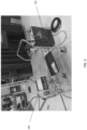
- FIG. 4 shows a prototype of an external module 100 (isolated DC voltage source) connectable in series with a test circuit employed to measure exciting current and losses according to exemplary embodiments of the present disclosure.
- the external module 100 is operable for injecting a varying DC offset voltage during the exciting current and loss test to thereby create an extra component to the external magnetic field being created by the test current.
- the extra component facilitates the rotation of magnetic domains, which translate in a reduction of the residual magnetism once the test voltage is removed.
- FIG. 5 shows an example test in progress including the prototype module 100 ( FIG. 4 ) being used in series with an insulation analyzer 104 (e.g ., insulation analyzer M4000, etc.).
- the voltage of the DC source 100 can be set to positive or negative values, e.g. , via the rotary selector switch knob 108 shown in FIG. 4 , etc.
- the test current is monitored while the polarity of the test current is changed depending on the slope.
- the objective is to establish a minimum measured current (or other appropriate criteria) that will correspond to the state of less magnetic bias in the core of the transformer. When this objective is achieved, the exciting current and losses can be then measured without the effects of residual magnetism in the core of the transformer being tested.
- the monitoring of the test current and changing of the polarity may be a manual process in which the test current is monitored manually by an operator while the operator manually changes the polarity of the test current depending on the slope.
- the monitoring of the test current and changing of the polarity may be an automatic process in which the test current is monitored automatically ( e.g., via software control, etc .) while the polarity of the test current is changed automatically ( e.g., via software control, etc. ) without requiring manual operation from an operator.
- FIG. 6 includes example test results obtained by using the prototype module 100 ( FIG. 4 ) while performing an exciting current and loss test on a 110 kilovolt (kV) to 22.9 kV and 2.5 megavolt-ampere (MVA) transformer.
- the first row of test results for the on-load tap changing transformer (OLTC 16L) corresponds to exciting current and loss results in the condition "as found". Both currents (milliamps) and loss (Watts) readings show a typical pattern of High-Low-High. More specifically, the higher current and loss readings are on the outer phases (H3-H1 and H2-H3). The lower current reading (2.919mA) and lower loss reading (25.639W) are exhibited on the center phase (H2-H1). Symmetry on the measurements is recognized ( e.g., via software, etc. ) and a rating is assigned based on the recognition of the phase pattern. This first set of test results was assigned a "Good” rating, which means that the expected phase pattern has been recognized.
- the second row of test results for the on-load tap changing transformer corresponds to exciting current and loss results after performing a DC winding resistance test on H3-H1, which magnetized the core.
- the residual magnetism creates an increase of measured current on that same phase.
- H3-H1 shows a current of 9.519mA, which is about 11% higher than the current of 8.559mA measured on H2-H3.
- this is recognized (e.g., via software, etc.) as "not confirming to a known phase pattern" and an "Investigate” rating is assigned.
- the third row of test results for the on-load tap changing transformer shows test results after using the prototype external module 100 ( FIGS. 4 and 5 ) and the methodology disclosed herein.
- the currents conform to an expected pattern of two high readings on the outer phases (H3-H1 and H2-H3) and one lower reading on the center phase (H1-H2).
- the magnitudes of the currents on the outer phases are lower after using the prototype external module 100 and methodology disclosed herein as compared with the first row of test results for "as found" condition. This indicates that the magnetic state of the core was driven to a point of minimum residual magnetism B r than the initial state, which is a signal of a clear removal of such magnetism by the prototype external module 100 and methodology disclosed herein.
- FIG. 7 is a line graph of measured exciting current in milliamps (mA RMS) and DC voltage in volts (V) versus Time.
- FIG. 7 shows the behavior of the measured current on phase H3-H1 with respect to DC voltage.
- the X-axis of the line graph corresponds to the time in seconds.
- the blue solid line corresponds to measured exciting current versus time.
- the peaks along the solid line where the current shows higher values represent a magnetized state of the core.
- the valleys along the solid line at which the RMS current is lower represent a demagnetized state of the core.
- positive and negative DC voltages can drive the core to saturation in a similar manner.
- the point of less magnetic bias (minimum measured RMS current) can be determined by observing or analyzing the behavior of the RMS current. And, the DC voltage can be turned off to thereby enable the measurement of the exciting current with a demagnetized core.
- This may include a manual process in which an operator, by observing or looking at the behavior of the current, can determine the point of less magnetic bias (minimum measured RMS current), manually turn the DC voltage off, and proceed with the measurement of the exciting current with a demagnetized core. Additionally, or alternatively, this may include an automated process in which the behavior of the current is analyzed by a system to determine the point of less magnetic bias (minimum measured current), and in response, the system automatically ( e.g., via software control, etc. ) turns the DC voltage off and proceeds with the measurement of the exciting current with a demagnetized core.
- FIG. 8 illustrates an exemplary method 220 for optimizing transformer exciting current and loss test results by dynamically managing core magnetic state according to exemplary embodiments of the present disclosure.
- the method 220 includes configuring the instrument and ramp to test voltage with DC offset voltage set to 0.0VDC.
- the DC offset voltage is then changed to a nominal positive value ( e.g., 5 to 50 VDC, etc. ) at 224.
- the method includes 220 measuring the rate of change of current. If the current is increasing, then the method 220 proceeds to 228 at which the DC offset voltage polarity is reversed, and the method returns to 226. But if the measured current at 226 is decreasing, then the method 220 proceeds to 230 to wait for a current minimum while the current is monitored.
- the method 220 proceeds to 234 at which the DC offset voltage is set to 0.0DVC, to thereby enable bypassing the DC source.
- the method 220 then proceeds to 236 at which the exciting current and losses can be measured without the effects of residual magnetism in the core of the transformer being tested.
- FIG. 9 illustrates a system 340 for optimizing transformer exciting current and loss test results by dynamically managing core magnetic state according to an exemplary embodiment.
- the system 340 includes a digital to analog converter (DAC) 342 within an isolated driver circuit 344, a step-up transformer 360, a main processor 350, and at least one relay 352.
- DAC digital to analog converter
- the digital to analog converter 342 is operable for feeding the isolated driver circuit 344.
- the isolated driver circuit 344 is coupled with a low voltage side of the high voltage winding of the step-up transformer 360.
- the digital to analog converter 342 is also coupled with a measurement reference point (Guard) 348.
- the system 340 is digitally controllable via the main processor 350, which provides digital controls.
- the main processor 350 is coupled and in communication with the low voltage source 354 and the device 356 that includes measurement channels.
- the relay 352 is available on the output to connect the low voltage side of the high voltage winding of the step-up transformer 360 directly to the Guard 348 of the relay matrix 358, thereby bypassing the isolated driver circuit 344.
- the relay matrix 358 is coupled with or includes a measurement lead 359 for connection with the transformer under test.
- the step-up transformer 360 is coupled with the low voltage source 354 and the isolated driver circuit 344.
- the step-up transformer 360 is operable for providing the high voltage within the system 340.
- the main reference or device 364 e.g., resistive divider, capacitive divider, etc.
- the output voltage as measured by the main reference 364 and the measured current from the measurement lead 359 are used to perform the calculations for the exciting current results.
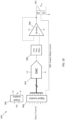
- FIG. 10 illustrates details of the driver circuit 344 shown in FIG. 9 according to an exemplary embodiment of the present disclosure.
- the driver circuit 344 includes an output relay control 362 configured to be operable for controlling operational (closed or open) status of the relay 352.
- the driver circuit 344 also includes a digital isolator 364 and a power isolator 365.
- the digital to analog converter (DAC) 342 is coupled in series with the digital isolator 364, a low pass filter 366, and an operational amplifier (Op-Amp) 368.
- DAC digital to analog converter
- FIG. 11 illustrates a system 440 for optimizing transformer exciting current and loss test results by dynamically managing core magnetic state according to another exemplary embodiment of the present disclosure.
- the system 440 includes a reversible DC source 442 that is part of an isolated driver circuit 444.
- the reversible DC source 442 may comprise a fixed value isolated DC source.
- the isolated driver circuit 444 is coupled with a low voltage side of a high voltage winding of a step-up transformer 460.
- the isolated driver circuit 444 is also coupled with a measurement reference point (Guard) 448.
- Guard measurement reference point
- the system 440 is digitally controllable via the main processor 450, which provides digital controls.
- the main processor 450 is coupled and in communication with the low voltage source 454 and the device 456 that includes measurement channels.
- the system 440 further includes at least one relay 452 available on the output to connect the low voltage side of the high voltage winding of the step-up transformer 460 directly to the Guard 448 of the relay matrix 458, thereby bypassing the isolated driver circuit 444.
- the relay matrix 458 is coupled with or includes a measurement lead 459 for connection with the transformer under test.
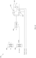
- FIG. 12 illustrates details of the driver circuit 444 shown in FIG. 11 according to an exemplary embodiment of the present disclosure.
- the driver circuit 444 includes a digital isolator 464 and a power isolator 465.
- the digital isolator 464 is between the DC supply 442 and DC control.
- the DC supply 442 is between the digital isolator 464 and first and second relays 472 and 474.
- the first and second relays 472 and 474 are configured to allow the output of the isolated driver circuit 444 to be electrically connected in the circuit with either a positive polarity or a negative polarity.
- FIG. 13 illustrates a system 540 for optimizing transformer exciting current and loss test results by dynamically managing core magnetic state according to another exemplary embodiment of the present disclosure.
- the system 540 includes a digital potentiometer 542 that is part of an isolated driver circuit 544.
- the isolated driver circuit 544 is coupled with a low voltage side of the high voltage winding of the step-up transformer 560.
- the isolated driver circuit 544 is also coupled with a measurement reference point (Guard) 548.
- the system 540 is digitally controllable via the main processor 550, which provides digital controls.
- the main processor 550 is coupled and in communication with the low voltage source 554 and the device 556 that includes measurement channels.
- At least one relay 552 is available on the output to connect the low voltage side of the high voltage winding of the step-up transformer 560 directly to the Guard 548 of the relay matrix 558, thereby bypassing the isolated driver circuit 544.
- the relay matrix 558 is coupled with or includes a measurement lead 559 for connection with the transformer under test.
- the step-up transformer 560 is coupled with the low voltage source 554 and the isolated driver circuit 544.
- FIG. 14 illustrates details of the driver circuit 544 shown in FIG. 13 according to an exemplary embodiment of the present disclosure.
- the driver circuit 544 includes an output relay control 562 configured to be operable for controlling operational (closed or open) status of the relay 552.
- the driver circuit 544 also includes a digital isolator 564 and a power isolator 565.
- the digital potentiometer 542 is coupled in series with the digital isolator 564, a low pass filter 566, and an operational amplifier (Op-Amp) 568.
- FIG. 15 illustrates a system 640 for optimizing transformer exciting current and loss test results by dynamically managing core magnetic state according to another exemplary embodiment of the present disclosure.
- the system 640 includes a DC coupled high voltage source 670 that allows for combining of a high voltage AC signal and a low voltage DC through a single supply.
- the DC coupled high voltage source 670 comprises a high voltage DC coupled amplifier in this illustrated embodiment.
- the DC coupled high voltage source 670 is coupled with a measurement reference point (Guard) 648 of the relay matrix 658.
- the relay matrix 658 is coupled with or includes a measurement lead 659 for connection with the transformer under test.
- the system 640 is digitally controllable via the main processor 650, which provides digital controls.
- the main processor 650 is coupled and in communication with the DC coupled high voltage source 670 and the device 656 that includes measurement channels.
- FIG. 16 illustrates a system 740 for optimizing transformer exciting current and loss test results by dynamically managing core magnetic state according to another exemplary embodiment of the present disclosure.
- the system 740 includes a DC injection circuit 744 coupled with a test instrument 776 via a measurement lead 759.
- the DC injection circuit 744 is also coupled with a device under test (DUT) 778 ( e.g ., a transformer, etc. ) .
- DUT device under test
- the test instrument 776 and DUT 778 are coupled via a high voltage lead 780.
- the DC injection circuit 744 is a standalone piece of equipment, operating independently from the test instrument.
- FIG. 17 illustrates details of the driver circuit 744 shown in FIG. 16 according to an exemplary embodiment of the present disclosure.
- the driver circuit 744 includes a driver 742 coupled with the relay 752, which is controllable by an output relay control 762.
- the driver circuit 744 also includes a gain/polarity control 782, a comparator 784, a differentiator 786, an AC to RMS converter 788, and an operational amplifier (Op-Amp) 790 coupled in series with the relay 752.
- Op-Amp operational amplifier
- the driver circuit 744 further includes a relay 772 configured to allow the output of the DC injection circuit 744 to be electrically connected in the circuit with either a positive polarity or a negative polarity.
- a low pass filter 766 is between the relay 772 and a programmable gain amplifier (PGA) 768.
- a method includes injecting a direct current (DC) offset voltage; adjusting at least one of a polarity and a magnitude of the DC offset voltage while monitoring a test current for one or more criteria; and bypassing a source of the DC offset voltage when the test current has satisfied the one or more criteria, whereby residual magnetism, if any, of the core of the transformer is minimized.
- DC direct current
- the method reduces residual magnetism of the core of the transformer thereby enabling optimization of the exciting current and loss test results of the transformer without the effects of the residual magnetism in the core and without requiring an independent demagnetization of the transformer.
- the method includes proceeding with the exciting current and loss testing of the transformer after reduction of the residual magnetism of the core of the transformer to a minimum residual magnetism.
- injecting the DC offset voltage comprises injecting the DC offset voltage via a DC voltage source in series with an alternating current (AC) coupled voltage supply; and adjusting at least one of a polarity and a magnitude of the DC offset voltage comprises reversing polarity and adjusting magnitude of the DC voltage source.
- AC alternating current
- the method includes: (A) monitoring a rate of change of the test current. If the monitored rate of change of the test current is increasing, then the method includes (a) reversing polarity of the DC offset voltage and the method returns to (A) monitoring a rate of change of the test current. Or, if the monitored rate of change of the test current is decreasing, then the method includes waiting for the test current to reach a minimum. And, if the test current is past the minimum, then the method includes reducing voltage by a predetermined amount and the method returns to (a) reversing polarity of the DC offset voltage; or if the test current is at the minimum or about at the minimum ( e.g., within 1% of the minimum, etc.
- the method includes setting the DC offset voltage to zero to bypass the source of the DC offset voltage.
- the method further includes (B) proceeding with the exciting current testing of the transformer after setting the DC offset voltage to zero to bypass the source of the DC offset voltage.
- injecting of the DC offset voltage creates an extra component to an external magnetic field being created by the test current, which said extra component facilitates rotation of magnetic domains that translates in a reduction of residual magnetism of the core of the transformer after bypassing and removing of test voltage of the source of the DC offset voltage.
- the one or more criteria comprises a test current minimum corresponding with a state of less magnetic bias and/or a demagnetized state of the core of the transformer.
- the method includes bypassing the source of the DC offset voltage when the test current has reached the test current minimum.
- the test current minimum may be within a range from about 1mA to 300mA for a 10Kv exciting voltage.
- bypassing the source of the DC offset voltage when the test current has satisfied the one or more criteria comprises using a relay to bypass the source of the DC offset voltage.
- bypassing the source of the DC offset voltage when the test current has satisfied the one or more criteria comprises setting the DC offset voltage to 0 VDC.
- a system is configured to be operable for dynamically managing magnetic state of a core of a transformer to enable optimization of exciting current test results of the transformer.
- the system comprises a direct current (DC) voltage source connectable with an alternating current (AC) coupled voltage supply.
- the DC voltage source is configured to support a maximum current supplied by the AC coupled voltage supply.
- the DC voltage source is configured to be operable for injecting a DC offset voltage.
- the system is configured to allow adjustment to at least one of a polarity and a magnitude of the DC offset voltage from the DC voltage source while monitoring a test current for one or more criteria.
- the system is also configured to allow bypassing of the DC voltage source when the test current has satisfied the one or more criteria, whereby residual magnetism, if any, of the core of the transformer is minimized.
- the DC voltage source is configured to be operable for injecting the DC offset voltage to create an extra component to an external magnetic field being created by the test current.
- the extra component facilitates rotation of magnetic domains that translates in a reduction of residual magnetism after removal of the test voltage from the DC voltage source.
- the one or more criteria comprises a test current minimum corresponding with a state of less magnetic bias and/or a demagnetized state of the core of the transformer.
- the system is configured to allow bypassing of the DC voltage source when the test current has reached the test current minimum.
- the test current minimum may be within a range from about 1mA to 300mA for a 10Kv exciting voltage.
- the system comprises at least one relay for selectively bypassing the DC voltage source when the test current has satisfied the one or more criteria.
- the DC voltage source comprises an isolated driver circuit including a digital to analog converter, a reversible DC source, or a digital potentiometer.
- the DC voltage source comprises an isolated driver circuit.
- a step-up transformer is coupled with a low voltage source and the isolated driver circuit.
- a relay matrix includes a measurement reference point and a measurement lead for connection with the transformer under test.
- a device including one or more measurement channels is coupled with the relay matrix.
- a processor is configured for digitally controlling the system. The processor is coupled with the low voltage source, the isolated driver circuit, and the device including the one or more measurement channels. At least one relay on an output of the isolated driver circuit is configured to connect a low voltage side of a high voltage winding of the step-up transformer to the measurement reference point to thereby bypass the isolated driver circuit.
- the DC voltage source comprises an isolated driver circuit including at least one relay on an output of the isolated driver circuit; an output relay control configured to be operable for controlling operational status of the at least one relay for selectively bypassing the isolated driver circuit; a digital isolator; a power isolator; a low pass filter; an operational amplifier; and a digital to analog converter operable for feeding the isolated driver circuit.
- the digital to analog converter is coupled in series with the digital isolator, the low pass filter, and the operational amplifier.
- the DC voltage source comprises an isolated driver circuit including a reversible DC supply operable for feeding the isolated driver circuit; a power isolator; a digital isolator between the reversible DC supply and a DC control; first and second relays coupled with the reversible DC supply; and a third relay on an output of the isolated driver circuit to selectively bypass the isolated driver circuit.
- the first and second relays are configured to allow an output of the isolated driver circuit to be electrically connected with either a positive polarity or a negative polarity.
- the DC voltage source comprises an isolated driver circuit including at least one relay on an output of the isolated driver circuit; an output relay control configured to be operable for controlling operational status of the at least one relay for selectively bypassing the isolated driver circuit; a digital isolator; a power isolator; a low pass filter; an operational amplifier; and a digital potentiometer operable for feeding the isolated driver circuit.
- the digital potentiometer is coupled in series with the digital isolator, the low pass filter, and the operational amplifier.
- the DC voltage source comprises a DC coupled high voltage source configured to be operable for combining a high voltage AC signal and a low voltage DC through a single supply.
- the DC voltage source comprises a high voltage DC coupled amplifier.
- the system includes a relay matrix including a measurement reference point and a measurement lead for connection with the transformer under test.
- the high voltage DC coupled amplifier coupled with the measurement reference point.
- a device including one or more measurement channels is coupled with the relay matrix.
- a processor is configured for digitally controlling the system. The processor is coupled with the high voltage DC coupled amplifier and the device including the one or more measurement channels.
- the DC voltage source comprises a DC injection circuit configured for connection with a test instrument and a device under test.
- the DC injection circuit includes a first relay on an output of the DC injection circuit; an output relay control configured to be operable for controlling operational status of the first relay for selectively bypassing the DC injection circuit; a power isolator; a driver coupled with the first relay; a gain/polarity control; a comparator; a differentiator; an AC to RMS converter; an operational amplifier coupled with the first relay and coupled in series with the AC to RMS converter, the differentiator, the comparator, and the gain/polarity control; a programmable gain amplifier coupled with the driver and gain control of the gain/polarity control; a low pass filter coupled with the programmable gain amplifier; and a second relay coupled with the low pass filter and polarity control of the gain/polarity control.
- exemplary systems and methods disclosed herein should not be limited to use with any one particular type or size of transformer or device under test.
- a test was performed on a 110kV delta-wye transformer. During this test, a DC bench supply was put in series with the return lead during a 10kV exciting current test. An ammeter was used to measure and log the actual current. The voltage from the DC supply was adjusted back and forth from +10 to -10 VDC, and the effect on the current in the loop was monitored. It was found that a minimum current was measured at what was considered a centered B-H curve.
- Advantages of being able to demagnetize the transformer's core while performing the exciting current and loss measurements include obtaining test results that truly represent the condition of the transformer and that are unaffected by the state of magnetization of the core. This is achieved without the need for additional equipment or leads to demagnetize the transformer.
- the process will require an amount of time (e.g., 10 to 20 seconds, etc. ) to run, which will depend on the voltage rating of the transformer being tested. This additional time is considerably less than what would be necessary to demagnetize the transformer using a different test set. If a transformer is being tested on multiple OLTC positions, the process may only have to be run once per phase on the first tap position.
- Example embodiments are provided so that this disclosure will be thorough and will fully convey the scope to those who are skilled in the art. Numerous specific details are set forth such as examples of specific components, devices, and methods, to provide a thorough understanding of embodiments of the present disclosure. It will be apparent to those skilled in the art that specific details need not be employed, that example embodiments may be embodied in many different forms and that neither should be construed to limit the scope of the disclosure. In some example embodiments, well-known processes, well-known device structures, and well-known technologies are not described in detail.
- first, second, third, etc. may be used herein to describe various elements, components, regions, layers and/or sections, these elements, components, regions, layers and/or sections should not be limited by these terms. These terms may be only used to distinguish one element, component, region, layer or section from another region, layer, or section. Terms such as “first,” “second,” and other numerical terms when used herein do not imply a sequence or order unless clearly indicated by the context. Thus, a first element, component, region, layer, or section discussed below could be termed a second element, component, region, layer, or section without departing from the teachings of the example embodiments.
- spatially relative terms such as “inner,” “outer,” “beneath,” “below,” “lower,” “above,” “upper,” and the like, may be used herein for ease of description to describe one element or feature's relationship to another element(s) or feature(s) as illustrated in the figures.
- Spatially relative terms may be intended to encompass different orientations of the device in use or operation in addition to the orientation depicted in the figures. For example, if the device in the figures is turned over, elements described as “below” or “beneath” other elements or features would then be oriented “above” the other elements or features.
- the example term “below” can encompass both an orientation of above and below.
- the device may be otherwise oriented (rotated 90 degrees or at other orientations) and the spatially relative descriptors used herein interpreted accordingly.
Landscapes
- Engineering & Computer Science (AREA)
- Power Engineering (AREA)
- Physics & Mathematics (AREA)
- Electromagnetism (AREA)
- General Physics & Mathematics (AREA)
- Measuring Instrument Details And Bridges, And Automatic Balancing Devices (AREA)
- Measurement Of Current Or Voltage (AREA)
Claims (15)
- Ein Verfahren zum Optimieren der Erregerstrom- und Verlusttestergebnisse eines Transformators durch dynamisches Verwalten des magnetischen Kernzustands, wobei das Verfahren umfasst:Injizieren einer Gleichstrom DC-Offsetspannung;Anpassen an mindestens eine Polarität und eine Größe der DC-Offsetspannung, während ein Teststrom auf ein oder mehrere Kriterien überwacht wird; und Umgehen einer Quelle der DC-Offsetspannung, wenn der Teststrom das eine oder die mehreren Kriterien erfüllt hat, wodurch ein Restmagnetismus, falls vorhanden, eines Kerns des Transformators minimiert wird; wobei das Verfahren dadurch gekennzeichnet ist, dass:
das Injizieren der DC-Offsetspannung das Injizieren der DC-Offsetspannung über eine DC-Spannungsquelle in Reihe mit einer mit Wechselstrom AC gekoppelten Spannungsversorgung umfasst; und das Anpassen von mindestens einer Polarität und einer Größe der DC-Offsetspannung das Umkehren der Polarität und das Anpassen der Größe der DC- Spannungsquelle umfasst. - Das Verfahren nach Anspruch 1, worin: das Verfahren das Fortsetzen der Erregerstrom- und Verlustprüfung des Transformators nach der Reduzierung des Restmagnetismus des Kerns des Transformators auf ein Minimum an Restmagnetismus umfasst.
- Das Verfahren nach einem der vorhergehenden Ansprüche, wobei das Verfahren Folgendes umfasst:(A) Überwachen einer Änderungsrate des Teststroms;(i) wenn die überwachte Änderungsrate des Teststroms zunimmt, umfasst das Verfahren (a) das Umkehren der Polarität der DC-Offsetspannung und das Verfahren kehrt zu (A) dem Überwachen einer Änderungsrate des Teststroms zurück; oder(ii) wenn die überwachte Änderungsrate des Teststroms abnimmt, umfasst das Verfahren das Warten, bis der Teststrom ein Minimum erreicht; und wenn der Teststrom das Minimum überschreitet, umfasst das Verfahren das Reduzieren der Spannung um einen vorgegebenen Betrag und das Verfahren kehrt zurück zu (a) dem Umkehren der Polarität der DC-Offsetspannung; oder wenn der Teststrom beim Minimum oder ungefähr beim Minimum liegt, umfasst das Verfahren das Setzen der DC-Offsetspannung auf Null, um die Quelle der DC-Offsetspannung zu umgehen.
- Das Verfahren nach Anspruch 3, das weiterhin (B) das Fortsetzen der Erregerstromprüfung des Transformators nach dem Setzen der DC-Offsetspannung auf Null umfasst, um die Quelle der DC-Offsetspannung zu umgehen.
- Das Verfahren nach einem der vorhergehenden Ansprüche, wobei:
das Injizieren der DC-Offsetspannung eine zusätzliche Komponente zu einem externen Magnetfeld erzeugt, das durch den Teststrom erzeugt wird, wobei diese zusätzliche Komponente die Rotation magnetischer Domänen erleichtert, was zu einer Verringerung des Restmagnetismus des Kerns des Transformators nach Umgehen und Entfernen der Testspannung der Quelle der DC-Offsetspannung führt; und/oder das eine oder die mehreren Kriterien ein Teststromminimum umfassen, das einem Zustand geringerer magnetischer Vorspannung und/oder einem entmagnetisierten Zustand des Kerns des Transformators entspricht; und das Verfahren das Umgehen der Quelle der DC-Offsetspannung umfasst, wenn der Teststrom das Teststromminimum erreicht hat. - Das Verfahren nach einem der vorhergehenden Ansprüche, wobei das Umgehen der Quelle der DC-Offsetspannung, wenn der Teststrom das eine oder die mehreren Kriterien erfüllt hat, umfasst: Verwenden eines Relais zum Umgehen der Quelle der DC-Offsetspannung; und/oder Einstellen der DC-Offsetspannung auf 0 VDC.
- Ein System, das so konfiguriert ist, dass es den magnetischen Zustand eines Kerns eines Transformators dynamisch verwalten kann, um eine Optimierung der Erregerstromtestergebnisse des Transformators zu ermöglichen, wobei das System umfasst: eine Gleichstrom-DC-Spannungsquelle, die mit einer Wechselstrom AC gekoppelten Spannungsversorgung verbindbar ist, die DC-Spannungsquelle ist so konfiguriert, dass sie einen von der AC gekoppelten Spannungsversorgung gelieferten Maximalstrom unterstützt, wobei die DC-Spannungsquelle so konfiguriert ist, dass sie zum Injizieren einer DC-Offsetspannung betriebsfähig ist; wobei das System so konfiguriert ist, dass es ermöglicht:
Anpassung an mindestens eine Polarität und/oder eine Größe der DC-Offsetspannung von der DC-Spannungsquelle, während ein Teststrom auf ein oder mehrere Kriterien überwacht wird; und Umgehen der DC-Spannungsquelle, wenn der Teststrom das eine oder die mehreren Kriterien erfüllt hat, wodurch ein Restmagnetismus, wenn vorhanden, des Kerns des Transformators minimiert wird; wobei das System dadurch gekennzeichnet ist, dass:
das Injizieren der DC-Offsetspannung das Injizieren der DC-Offsetspannung über eine DC-Spannungsquelle in Reihe mit einer Wechselstrom AC gekoppelten Spannungsversorgung umfasst; und das Anpassen von mindestens einer Polarität und einer Größe der DC-Offsetspannung das Umkehren der Polarität und das Anpassen der Größe der DC-Spannungsquelle umfasst. - Das System nach Anspruch 7, wobei die DC-Spannungsquelle eine isolierte Treiberschaltung umfasst und wobei das System umfasst:
eine Niederspannungsquelle; einen Step-Up Transformer, der mit der Niederspannungsquelle und der isolierten Treiberschaltung gekoppelt ist; eine Relaismatrix, die einen Messreferenzpunkt und eine Messleitung zur Verbindung mit dem zu testenden Transformator umfasst; ein Gerät, das einen oder mehrere Messkanäle umfasst und mit der Relaismatrix gekoppelt ist; einen Prozessor, der zur digitalen Steuerung des Systems konfiguriert ist, wobei der Prozessor mit der Niederspannungsquelle, der isolierten Treiberschaltung und dem Gerät, das den einen oder mehrere Messkanäle umfasst, gekoppelt ist; und mindestens ein Relais an einem Ausgang der isolierten Treiberschaltung, das so konfiguriert ist, dass es eine Niederspannungsseite einer Hochspannungswicklung des Step-Up Transformers mit dem Messreferenzpunkt verbindet, um dadurch die isolierte Treiberschaltung zu umgehen. - Das System nach Anspruch 7, wobei die DC-Spannungsquelle eine isolierte Treiberschaltung umfasst, die umfasst:mindestens ein Relais an einem Ausgang der isolierten Treiberschaltung; eine Ausgangsrelaissteuerung, die so konfiguriert ist, dass sie den Betriebsstatus des mindestens einen Relais steuert, um die isolierte Treiberschaltung selektiv zu umgehen;einen digitalen Isolator;einen Leistungsisolator;einen Tiefpassfilter;einen Operationsverstärker; undeinen Digital-Analog-Umsetzer, der die isolierte Treiberschaltung speist, wobei der Digital-Analog-Umsetzer in Reihe mit dem digitalen Isolator, dem Tiefpassfilter und dem Operationsverstärker geschaltet ist.
- Das System nach Anspruch 7, wobei die DC-Spannungsquelle eine isolierte Treiberschaltung umfasst, die umfasst:eine umkehrbare DC-Stromversorgung, die zur Versorgung der isolierten Treiberschaltung geeignet ist;einen Leistungsisolator;einen digitalen Isolator zwischen der umkehrbaren DC-Stromversorgung und einer DC-Stromsteuerung;erstes und zweites Relais sind mit der umkehrbaren DC-Stromversorgung gekoppelt, das erste und zweite Relais sind so konfiguriert, dass ein Ausgang der isolierten Treiberschaltung elektrisch entweder mit einer positiven oder einer negativen Polarität verbunden werden kann; und ein drittes Relais an einem Ausgang der isolierten Treiberschaltung, um die isolierte Treiberschaltung selektiv zu umgehen.
- Das System nach Anspruch 7, wobei die DC-Spannungsquelle eine isolierte Treiberschaltung umfasst, die umfasst:mindestens ein Relais an einem Ausgang der isolierten Treiberschaltung; eine Ausgangsrelaissteuerung, die so konfiguriert ist, dass sie den Betriebszustand des mindestens einen Relais steuert, um die isolierte Treiberschaltung selektiv zu umgehen;einen digitalen Isolator;einen Leistungsisolator;einen Tiefpassfilter;einen Operationsverstärker; undein digitales Potentiometer, das die isolierte Treiberschaltung mit Strom versorgen kann, wobei das digitale Potentiometer in Reihe mit dem digitalen Isolator, dem Tiefpassfilter und dem Operationsverstärker geschaltet ist.
- Das System nach Anspruch 7, wobei die DC-Spannungsquelle einen Hochspannungs-DC-gekoppelten Verstärker umfasst und wobei das System umfasst:eine Relaismatrix mit einem Messreferenzpunkt und einer Messleitung zur Verbindung mit dem zu testenden Transformator, wobei der Hochspannungs-DC-gekoppelte Verstärker mit dem Messreferenzpunkt gekoppelt ist;ein Gerät mit einem oder mehreren Messkanälen und gekoppelt mit der Relaismatrix;und einen Prozessor, der zur digitalen Steuerung des Systems konfiguriert ist, wobei der Prozessor mit dem Hochspannungs-DC-gekoppelten Verstärker gekoppelt ist und das Gerät die einen oder mehrere Messkanäle umfasst.
- Das System nach Anspruch 7, wobei die DC-Spannungsquelle eine DC-Strom-Injektionsschaltung umfasst, die für den Anschluss an ein Testinstrument und ein zu testendes Gerät konfiguriert ist, wobei die DC-Injektionsschaltung umfasst:ein erstes Relais an einem Ausgang der DC-Injektionsschaltung; eine Ausgangsrelaissteuerung, die so konfiguriert ist, dass sie zum Steuern des Betriebsstatus des ersten Relais zum selektiven Umgehen der DC-Injektionsschaltung betriebsfähig ist;einen Leistungsisolator;einen Treiber, der mit dem ersten Relais gekoppelt ist;eine Verstärkungs-/Polaritätssteuerung;einen Komparator;einen Differenzierer;einen AC-zu-RMS-Umsetzer;einen Operationsverstärker, der mit dem ersten Relais gekoppelt ist, wobei der Operationsverstärker in Reihe mit dem AC-zu-RMS-Umsetzer, dem Differenzierer, dem Komparator und der Verstärkungs-/Polaritätssteuerung gekoppelt ist; einen programmierbaren Verstärkungsverstärker, der mit dem Treiber und der Verstärkungssteuerung der Verstärkungs-/Polaritätssteuerung gekoppelt ist; einen Tiefpassfilter, der mit dem programmierbaren Verstärkungsverstärker gekoppelt ist; und ein zweites Relais, das mit dem Tiefpassfilter und der Polaritätssteuerung der Verstärkungs-/Polaritätssteuerung gekoppelt ist.
- Das System nach Anspruch 7, wobei die DC-Spannungsquelle so konfiguriert ist, dass sie zum Injizieren der DC-Offsetspannung betriebsfähig ist, um eine zusätzliche Komponente zu einem externen Magnetfeld zu erzeugen, das durch den Teststrom erzeugt wird, wobei die zusätzliche Komponente die Rotation magnetischer Domänen erleichtert, was zu einer Verringerung des Restmagnetismus nach dem Entfernen der Testspannung von der DC-Spannungsquelle führt; und/oder die DC-Spannungsquelle eine DC gekoppelte Hochspannungsquelle umfasst, die so konfiguriert ist, dass sie zum Kombinieren eines Hochspannungs-AC-Signals und eines Niederspannungs-DC-Stromsignals über eine einzige Versorgung betriebsfähig ist; und/oder die DC-Spannungsquelle eine isolierte Treiberschaltung umfasst, die einen Digital-Analog-Umsetzer, eine umkehrbare DC-Stromquelle oder ein digitales Potentiometer umfasst.
- Das System nach Anspruch 7, wobei das eine oder die mehreren Kriterien ein Teststromminimum umfassen, das einem Zustand geringerer magnetischer Vorspannung und/oder einem entmagnetisierten Zustand des Kerns des Transformators entspricht; und das System so konfiguriert ist, dass es ein Umgehen der DC-Spannungsquelle zulässt, wenn der Teststrom das Teststromminimum erreicht hat; und/oder das System mindestens ein Relais zum selektiven Umgehen der DC-Spannungsquelle umfasst, wenn der Teststrom das eine oder die mehreren Kriterien erfüllt hat.
Applications Claiming Priority (2)
| Application Number | Priority Date | Filing Date | Title |
|---|---|---|---|
| US202263298122P | 2022-01-10 | 2022-01-10 | |
| US17/721,101 US12094651B2 (en) | 2022-01-10 | 2022-04-14 | Optimizing transformer exciting current and loss test results by dynamically managing core magnetic state |
Publications (3)
| Publication Number | Publication Date |
|---|---|
| EP4209795A1 EP4209795A1 (de) | 2023-07-12 |
| EP4209795B1 true EP4209795B1 (de) | 2024-10-23 |
| EP4209795C0 EP4209795C0 (de) | 2024-10-23 |
Family
ID=81603604
Family Applications (1)
| Application Number | Title | Priority Date | Filing Date |
|---|---|---|---|
| EP22172536.9A Active EP4209795B1 (de) | 2022-01-10 | 2022-05-10 | Optimierter transformatorerregerstrom und -verlusttestergebnisse durch dynamische verwaltung des kernmagnetzustands |
Country Status (3)
| Country | Link |
|---|---|
| US (1) | US12094651B2 (de) |
| EP (1) | EP4209795B1 (de) |
| CA (1) | CA3183271A1 (de) |
Families Citing this family (2)
| Publication number | Priority date | Publication date | Assignee | Title |
|---|---|---|---|---|
| CN121186549B (zh) * | 2025-11-26 | 2026-02-27 | 西安交通大学 | 一种高压电缆缓冲层受潮缺陷放电的状态评估方法及系统 |
| CN121617777B (zh) * | 2026-01-30 | 2026-04-17 | 国网四川省电力公司电力科学研究院 | 一种基于剩磁实时跟踪与自适应调控的电力设备退磁方法及系统 |
Family Cites Families (4)
| Publication number | Priority date | Publication date | Assignee | Title |
|---|---|---|---|---|
| US6590380B2 (en) * | 2000-12-11 | 2003-07-08 | Thomas G. Edel | Method and apparatus for compensation of current transformer error |
| US11601041B2 (en) * | 2016-12-31 | 2023-03-07 | Orris Dent | System for preventing transformer saturation |
| US10203364B2 (en) | 2017-02-17 | 2019-02-12 | Doble Engineering Company | System and method for performing transformer diagnostics |
| CN110828101B (zh) | 2018-08-14 | 2022-02-11 | 广东电网有限责任公司广州供电局 | 电力变压器消磁及剩磁测量的装置 |
-
2022
- 2022-04-14 US US17/721,101 patent/US12094651B2/en active Active
- 2022-05-10 EP EP22172536.9A patent/EP4209795B1/de active Active
- 2022-11-30 CA CA3183271A patent/CA3183271A1/en active Pending
Also Published As
| Publication number | Publication date |
|---|---|
| US20230223177A1 (en) | 2023-07-13 |
| US12094651B2 (en) | 2024-09-17 |
| EP4209795C0 (de) | 2024-10-23 |
| CA3183271A1 (en) | 2023-07-10 |
| EP4209795A1 (de) | 2023-07-12 |
Similar Documents
| Publication | Publication Date | Title |
|---|---|---|
| Abeywickrama et al. | Effect of core magnetization on frequency response analysis (FRA) of power transformers | |
| US20150168478A1 (en) | Method and apparatus for measuring load tap changer characteristics | |
| EP4209795A1 (de) | Optimierter transformatorerregerstrom und -verlusttestergebnisse durch dynamische verwaltung des kernmagnetzustands | |
| KR20170102456A (ko) | 변압기 시험 장치 및 변압기 시험 방법 | |
| RU2668614C1 (ru) | Устройство для испытания трансформатора и способ испытания трансформатора | |
| Zhang et al. | Improved flux-controlled VFCV strategy for eliminating and measuring the residual flux of three-phase transformers | |
| CN107170563A (zh) | 一种具有自校准功能的电流互感器及其自校准方法 | |
| US4573012A (en) | Method and apparatus for measuring core loss of a laminated ferromagnetic structure | |
| Banaszak et al. | Influence of a tap changer position on the transformer's frequency response | |
| RU2364876C1 (ru) | Способ определения параметров т-образной схемы замещения трехфазного трехобмоточного трансформатора в рабочем режиме | |
| EP0216001A1 (de) | Verfahren zur Prüfung von Primärwicklungen induktiver Spannungswandler | |
| US3034021A (en) | Magnetic testing system | |
| Bertrand et al. | A simulation model for transformer internal faults base for the study of protection and monitoring systems | |
| Dupuis | An introduction to electrical diagnostic testing of power transformers | |
| RU2354982C1 (ru) | Способ диагностики магнитной системы трансформатора | |
| Lachman et al. | Influence of single-phase excitation and magnetizing reactance on transformer leakage reactance measurement | |
| JP3847556B2 (ja) | 電磁誘導機器の健全性評価方法および試験方法 | |
| RU2105987C1 (ru) | Способ проверки исправности вторичных цепей трансформаторов тока | |
| Oliveira et al. | A coupled electromagnetic transformer model for the analysis of winding inter-turn short-circuits | |
| Würde et al. | Influence of the Power Factor on the Vibration Behavior of Transformers for Primary and Secondary Distribution | |
| Pütter et al. | Reliable demagnetization of transformer cores | |
| Denissov et al. | Integrated test van for maintenance and diagnosis of power transformers | |
| Zhang et al. | Flux-controlled methods for demagnetization of transformer iron core: a comparative study | |
| JPH1068744A (ja) | 直流電流センサー | |
| Freiburg et al. | Influence of Remanent Magnetization on the Accuracy of Industry Typical Metering Current Transformers |
Legal Events
| Date | Code | Title | Description |
|---|---|---|---|
| PUAI | Public reference made under article 153(3) epc to a published international application that has entered the european phase |
Free format text: ORIGINAL CODE: 0009012 |
|
| STAA | Information on the status of an ep patent application or granted ep patent |
Free format text: STATUS: THE APPLICATION HAS BEEN PUBLISHED |
|
| AK | Designated contracting states |
Kind code of ref document: A1 Designated state(s): AL AT BE BG CH CY CZ DE DK EE ES FI FR GB GR HR HU IE IS IT LI LT LU LV MC MK MT NL NO PL PT RO RS SE SI SK SM TR |
|
| STAA | Information on the status of an ep patent application or granted ep patent |
Free format text: STATUS: REQUEST FOR EXAMINATION WAS MADE |
|
| 17P | Request for examination filed |
Effective date: 20230807 |
|
| RBV | Designated contracting states (corrected) |
Designated state(s): AL AT BE BG CH CY CZ DE DK EE ES FI FR GB GR HR HU IE IS IT LI LT LU LV MC MK MT NL NO PL PT RO RS SE SI SK SM TR |
|
| STAA | Information on the status of an ep patent application or granted ep patent |
Free format text: STATUS: EXAMINATION IS IN PROGRESS |
|
| 17Q | First examination report despatched |
Effective date: 20231027 |
|
| GRAP | Despatch of communication of intention to grant a patent |
Free format text: ORIGINAL CODE: EPIDOSNIGR1 |
|
| STAA | Information on the status of an ep patent application or granted ep patent |
Free format text: STATUS: GRANT OF PATENT IS INTENDED |
|
| INTG | Intention to grant announced |
Effective date: 20240521 |
|
| GRAS | Grant fee paid |
Free format text: ORIGINAL CODE: EPIDOSNIGR3 |
|
| GRAA | (expected) grant |
Free format text: ORIGINAL CODE: 0009210 |
|
| STAA | Information on the status of an ep patent application or granted ep patent |
Free format text: STATUS: THE PATENT HAS BEEN GRANTED |
|
| AK | Designated contracting states |
Kind code of ref document: B1 Designated state(s): AL AT BE BG CH CY CZ DE DK EE ES FI FR GB GR HR HU IE IS IT LI LT LU LV MC MK MT NL NO PL PT RO RS SE SI SK SM TR |
|
| REG | Reference to a national code |
Ref country code: GB Ref legal event code: FG4D |
|
| REG | Reference to a national code |
Ref country code: CH Ref legal event code: EP |
|
| REG | Reference to a national code |
Ref country code: DE Ref legal event code: R096 Ref document number: 602022006983 Country of ref document: DE |
|
| REG | Reference to a national code |
Ref country code: IE Ref legal event code: FG4D |
|
| U01 | Request for unitary effect filed |
Effective date: 20241028 |
|
| U07 | Unitary effect registered |
Designated state(s): AT BE BG DE DK EE FI FR IT LT LU LV MT NL PT RO SE SI Effective date: 20241104 |
|
| PG25 | Lapsed in a contracting state [announced via postgrant information from national office to epo] |
Ref country code: IS Free format text: LAPSE BECAUSE OF FAILURE TO SUBMIT A TRANSLATION OF THE DESCRIPTION OR TO PAY THE FEE WITHIN THE PRESCRIBED TIME-LIMIT Effective date: 20250223 Ref country code: HR Free format text: LAPSE BECAUSE OF FAILURE TO SUBMIT A TRANSLATION OF THE DESCRIPTION OR TO PAY THE FEE WITHIN THE PRESCRIBED TIME-LIMIT Effective date: 20241023 |
|
| PG25 | Lapsed in a contracting state [announced via postgrant information from national office to epo] |
Ref country code: ES Free format text: LAPSE BECAUSE OF FAILURE TO SUBMIT A TRANSLATION OF THE DESCRIPTION OR TO PAY THE FEE WITHIN THE PRESCRIBED TIME-LIMIT Effective date: 20241023 |
|
| PG25 | Lapsed in a contracting state [announced via postgrant information from national office to epo] |
Ref country code: GR Free format text: LAPSE BECAUSE OF FAILURE TO SUBMIT A TRANSLATION OF THE DESCRIPTION OR TO PAY THE FEE WITHIN THE PRESCRIBED TIME-LIMIT Effective date: 20250124 |
|
| PG25 | Lapsed in a contracting state [announced via postgrant information from national office to epo] |
Ref country code: PL Free format text: LAPSE BECAUSE OF FAILURE TO SUBMIT A TRANSLATION OF THE DESCRIPTION OR TO PAY THE FEE WITHIN THE PRESCRIBED TIME-LIMIT Effective date: 20241023 |
|
| PG25 | Lapsed in a contracting state [announced via postgrant information from national office to epo] |
Ref country code: RS Free format text: LAPSE BECAUSE OF FAILURE TO SUBMIT A TRANSLATION OF THE DESCRIPTION OR TO PAY THE FEE WITHIN THE PRESCRIBED TIME-LIMIT Effective date: 20250123 |
|
| PG25 | Lapsed in a contracting state [announced via postgrant information from national office to epo] |
Ref country code: SM Free format text: LAPSE BECAUSE OF FAILURE TO SUBMIT A TRANSLATION OF THE DESCRIPTION OR TO PAY THE FEE WITHIN THE PRESCRIBED TIME-LIMIT Effective date: 20241023 |
|
| PGFP | Annual fee paid to national office [announced via postgrant information from national office to epo] |
Ref country code: NO Payment date: 20250530 Year of fee payment: 4 |
|
| PGFP | Annual fee paid to national office [announced via postgrant information from national office to epo] |
Ref country code: CH Payment date: 20250601 Year of fee payment: 4 |
|
| PG25 | Lapsed in a contracting state [announced via postgrant information from national office to epo] |
Ref country code: SK Free format text: LAPSE BECAUSE OF FAILURE TO SUBMIT A TRANSLATION OF THE DESCRIPTION OR TO PAY THE FEE WITHIN THE PRESCRIBED TIME-LIMIT Effective date: 20241023 |
|
| PGFP | Annual fee paid to national office [announced via postgrant information from national office to epo] |
Ref country code: TR Payment date: 20250428 Year of fee payment: 4 |
|
| PG25 | Lapsed in a contracting state [announced via postgrant information from national office to epo] |
Ref country code: CZ Free format text: LAPSE BECAUSE OF FAILURE TO SUBMIT A TRANSLATION OF THE DESCRIPTION OR TO PAY THE FEE WITHIN THE PRESCRIBED TIME-LIMIT Effective date: 20241023 |
|
| PLBE | No opposition filed within time limit |
Free format text: ORIGINAL CODE: 0009261 |
|
| STAA | Information on the status of an ep patent application or granted ep patent |
Free format text: STATUS: NO OPPOSITION FILED WITHIN TIME LIMIT |
|
| U21 | Renewal fee for the european patent with unitary effect paid with additional fee |
Year of fee payment: 4 Effective date: 20250728 |
|
| 26N | No opposition filed |
Effective date: 20250724 |
|
| PG25 | Lapsed in a contracting state [announced via postgrant information from national office to epo] |
Ref country code: MC Free format text: LAPSE BECAUSE OF FAILURE TO SUBMIT A TRANSLATION OF THE DESCRIPTION OR TO PAY THE FEE WITHIN THE PRESCRIBED TIME-LIMIT Effective date: 20241023 |
|
| PG25 | Lapsed in a contracting state [announced via postgrant information from national office to epo] |
Ref country code: IE Free format text: LAPSE BECAUSE OF NON-PAYMENT OF DUE FEES Effective date: 20250510 |