EP4209693A1 - Three-stage speed-change mechanism - Google Patents
Three-stage speed-change mechanism Download PDFInfo
- Publication number
- EP4209693A1 EP4209693A1 EP23150640.3A EP23150640A EP4209693A1 EP 4209693 A1 EP4209693 A1 EP 4209693A1 EP 23150640 A EP23150640 A EP 23150640A EP 4209693 A1 EP4209693 A1 EP 4209693A1
- Authority
- EP
- European Patent Office
- Prior art keywords
- speed
- wheel
- assembly
- change
- initial
- Prior art date
- Legal status (The legal status is an assumption and is not a legal conclusion. Google has not performed a legal analysis and makes no representation as to the accuracy of the status listed.)
- Granted
Links
Images



Classifications
-
- F—MECHANICAL ENGINEERING; LIGHTING; HEATING; WEAPONS; BLASTING
- F16—ENGINEERING ELEMENTS AND UNITS; GENERAL MEASURES FOR PRODUCING AND MAINTAINING EFFECTIVE FUNCTIONING OF MACHINES OR INSTALLATIONS; THERMAL INSULATION IN GENERAL
- F16H—GEARING
- F16H3/00—Toothed gearings for conveying rotary motion with variable gear ratio or for reversing rotary motion
- F16H3/02—Toothed gearings for conveying rotary motion with variable gear ratio or for reversing rotary motion without gears having orbital motion
- F16H3/08—Toothed gearings for conveying rotary motion with variable gear ratio or for reversing rotary motion without gears having orbital motion exclusively or essentially with continuously meshing gears, that can be disengaged from their shafts
- F16H3/087—Toothed gearings for conveying rotary motion with variable gear ratio or for reversing rotary motion without gears having orbital motion exclusively or essentially with continuously meshing gears, that can be disengaged from their shafts characterised by the disposition of the gears
- F16H3/089—Toothed gearings for conveying rotary motion with variable gear ratio or for reversing rotary motion without gears having orbital motion exclusively or essentially with continuously meshing gears, that can be disengaged from their shafts characterised by the disposition of the gears all of the meshing gears being supported by a pair of parallel shafts, one being the input shaft and the other the output shaft, there being no countershaft involved
-
- F—MECHANICAL ENGINEERING; LIGHTING; HEATING; WEAPONS; BLASTING
- F16—ENGINEERING ELEMENTS AND UNITS; GENERAL MEASURES FOR PRODUCING AND MAINTAINING EFFECTIVE FUNCTIONING OF MACHINES OR INSTALLATIONS; THERMAL INSULATION IN GENERAL
- F16H—GEARING
- F16H3/00—Toothed gearings for conveying rotary motion with variable gear ratio or for reversing rotary motion
- F16H3/02—Toothed gearings for conveying rotary motion with variable gear ratio or for reversing rotary motion without gears having orbital motion
- F16H3/08—Toothed gearings for conveying rotary motion with variable gear ratio or for reversing rotary motion without gears having orbital motion exclusively or essentially with continuously meshing gears, that can be disengaged from their shafts
- F16H3/10—Toothed gearings for conveying rotary motion with variable gear ratio or for reversing rotary motion without gears having orbital motion exclusively or essentially with continuously meshing gears, that can be disengaged from their shafts with one or more one-way clutches as an essential feature
-
- F—MECHANICAL ENGINEERING; LIGHTING; HEATING; WEAPONS; BLASTING
- F16—ENGINEERING ELEMENTS AND UNITS; GENERAL MEASURES FOR PRODUCING AND MAINTAINING EFFECTIVE FUNCTIONING OF MACHINES OR INSTALLATIONS; THERMAL INSULATION IN GENERAL
- F16H—GEARING
- F16H57/00—General details of gearing
- F16H57/02—Gearboxes; Mounting gearing therein
-
- F—MECHANICAL ENGINEERING; LIGHTING; HEATING; WEAPONS; BLASTING
- F16—ENGINEERING ELEMENTS AND UNITS; GENERAL MEASURES FOR PRODUCING AND MAINTAINING EFFECTIVE FUNCTIONING OF MACHINES OR INSTALLATIONS; THERMAL INSULATION IN GENERAL
- F16H—GEARING
- F16H57/00—General details of gearing
- F16H57/02—Gearboxes; Mounting gearing therein
- F16H57/021—Shaft support structures, e.g. partition walls, bearing eyes, casing walls or covers with bearings
-
- F—MECHANICAL ENGINEERING; LIGHTING; HEATING; WEAPONS; BLASTING
- F16—ENGINEERING ELEMENTS AND UNITS; GENERAL MEASURES FOR PRODUCING AND MAINTAINING EFFECTIVE FUNCTIONING OF MACHINES OR INSTALLATIONS; THERMAL INSULATION IN GENERAL
- F16H—GEARING
- F16H57/00—General details of gearing
- F16H57/02—Gearboxes; Mounting gearing therein
- F16H57/023—Mounting or installation of gears or shafts in the gearboxes, e.g. methods or means for assembly
-
- F—MECHANICAL ENGINEERING; LIGHTING; HEATING; WEAPONS; BLASTING
- F16—ENGINEERING ELEMENTS AND UNITS; GENERAL MEASURES FOR PRODUCING AND MAINTAINING EFFECTIVE FUNCTIONING OF MACHINES OR INSTALLATIONS; THERMAL INSULATION IN GENERAL
- F16H—GEARING
- F16H57/00—General details of gearing
- F16H57/02—Gearboxes; Mounting gearing therein
- F16H57/031—Gearboxes; Mounting gearing therein characterised by covers or lids for gearboxes
-
- H—ELECTRICITY
- H02—GENERATION; CONVERSION OR DISTRIBUTION OF ELECTRIC POWER
- H02K—DYNAMO-ELECTRIC MACHINES
- H02K7/00—Arrangements for handling mechanical energy structurally associated with dynamo-electric machines, e.g. structural association with mechanical driving motors or auxiliary dynamo-electric machines
- H02K7/10—Structural association with clutches, brakes, gears, pulleys or mechanical starters
- H02K7/116—Structural association with clutches, brakes, gears, pulleys or mechanical starters with gears
-
- F—MECHANICAL ENGINEERING; LIGHTING; HEATING; WEAPONS; BLASTING
- F16—ENGINEERING ELEMENTS AND UNITS; GENERAL MEASURES FOR PRODUCING AND MAINTAINING EFFECTIVE FUNCTIONING OF MACHINES OR INSTALLATIONS; THERMAL INSULATION IN GENERAL
- F16H—GEARING
- F16H57/00—General details of gearing
- F16H57/02—Gearboxes; Mounting gearing therein
- F16H2057/02034—Gearboxes combined or connected with electric machines
-
- F—MECHANICAL ENGINEERING; LIGHTING; HEATING; WEAPONS; BLASTING
- F16—ENGINEERING ELEMENTS AND UNITS; GENERAL MEASURES FOR PRODUCING AND MAINTAINING EFFECTIVE FUNCTIONING OF MACHINES OR INSTALLATIONS; THERMAL INSULATION IN GENERAL
- F16H—GEARING
- F16H57/00—General details of gearing
- F16H57/02—Gearboxes; Mounting gearing therein
- F16H2057/02039—Gearboxes for particular applications
- F16H2057/02043—Gearboxes for particular applications for vehicle transmissions
-
- F—MECHANICAL ENGINEERING; LIGHTING; HEATING; WEAPONS; BLASTING
- F16—ENGINEERING ELEMENTS AND UNITS; GENERAL MEASURES FOR PRODUCING AND MAINTAINING EFFECTIVE FUNCTIONING OF MACHINES OR INSTALLATIONS; THERMAL INSULATION IN GENERAL
- F16H—GEARING
- F16H57/00—General details of gearing
- F16H57/02—Gearboxes; Mounting gearing therein
- F16H57/023—Mounting or installation of gears or shafts in the gearboxes, e.g. methods or means for assembly
- F16H2057/0235—Mounting or installation of gears or shafts in the gearboxes, e.g. methods or means for assembly specially adapted to allow easy accessibility and repair
-
- F—MECHANICAL ENGINEERING; LIGHTING; HEATING; WEAPONS; BLASTING
- F16—ENGINEERING ELEMENTS AND UNITS; GENERAL MEASURES FOR PRODUCING AND MAINTAINING EFFECTIVE FUNCTIONING OF MACHINES OR INSTALLATIONS; THERMAL INSULATION IN GENERAL
- F16H—GEARING
- F16H2200/00—Transmissions for multiple ratios
- F16H2200/0021—Transmissions for multiple ratios specially adapted for electric vehicles
-
- F—MECHANICAL ENGINEERING; LIGHTING; HEATING; WEAPONS; BLASTING
- F16—ENGINEERING ELEMENTS AND UNITS; GENERAL MEASURES FOR PRODUCING AND MAINTAINING EFFECTIVE FUNCTIONING OF MACHINES OR INSTALLATIONS; THERMAL INSULATION IN GENERAL
- F16H—GEARING
- F16H2200/00—Transmissions for multiple ratios
- F16H2200/003—Transmissions for multiple ratios characterised by the number of forward speeds
- F16H2200/0039—Transmissions for multiple ratios characterised by the number of forward speeds the gear ratios comprising three forward speeds
Definitions
- the present invention relates generally to the technical field of speed change.
- An electric motorcycle makes use of an increase of decrease of a speed of an electric motor to change a speed thereof. Due to being limited by the size and insufficiency of available space, it is generally not possible to install a large-sized speed-change mechanism that is of a sophisticated structure. Generally speaking, for traveling at a low speed, the rotational speed of the motor is kept at 1,000-2,000rpm to provide a better performance, yet when the electrical motorcycle needs to travel at a high speed, the rotational speed of the motor is raised to higher than 2,000rpm. This would deteriorate the performance of the motor. Thus, the best way for handling such a problem is to provide a speed-change mechanism to keep the motor at 1,000-2,000rpm, while an output shaft drives an output wheel to reach a rotational speed of higher than 2,000rpm.
- the speed-change mechanisms that are currently available are classified in two types, one being gear-based speed changer, which has a better efficiency for speed switching, but has a complicated structure so that the cost is high and servicing is difficult, and there are sometimes situations of setting back in increasing or decreasing speed during an operation of speed change.
- the second one is continuously variable transmission (CVT), which, although being simplified in structure to thereby reduce the cost and be easy to service, has a poor efficiency of speed switching.
- CVT continuously variable transmission
- the primary objective of the present invention is to provide an effective and simplified structure, of which a structural arrangement is used to effectively reduce the difficulty of assembling and servicing so as to ease maintenance and replacement and achieve an effect of time saving and labor saving.
- Another objective of the present invention is to provide three-stage speed change, and direct transfer of power being available during speed change, so as to achieve a purpose of increasing the speed and reliability of speed change.
- a further objective of the present invention is to eliminate setting back in a process of speed change to achieve a purpose of stable and comfortable speed change.
- FIGS. 1 , 2 , and 3 A structure of the present invention is shown in FIGS. 1 , 2 , and 3 , and comprises a drive assembly 20, an input assembly 30 and an output assembly 40 arranged in an interior of a casing 10.
- FIGS. 3 , 4 , 5 , 6 , and 7 A detailed structure of a preferred embodiment is illustrated in FIGS. 3 , 4 , 5 , 6 , and 7 .
- the casing 10 is provided with a first end cover 11 and a second end cover 12 respectively mounted to two ends thereof to protect and support the drive assembly 20, the input assembly 30 and the output assembly 40 of which axes are arranged in parallel.
- the drive assembly 20 comprises an electrical motor 21.
- the electrical motor 21 has an output shaft that comprises a drive wheel 22 that drives the input assembly 30.
- the drive wheel 22 is set in mating and transmitting engagement with the input assembly 30 by means of a gear ratio adjusting assembly 25.
- the gear ratio adjusting assembly 25 comprises a first gear 26 and a second gear 27 that are coaxial and are rotatable in synchronization with each other, wherein the first gear 26 is in mating engagement with the drive wheel 22 of the electrical motor 21.
- the input assembly 30 comprises a transmission shaft 31 that is parallel with an axis of the drive wheel 22 of the drive assembly 20, as shown in FIGS. 4 and 6 .
- An end of the transmission shaft 31 is provided with a driven wheel 32 fixedly mounted thereto to be driven by the drive wheel 22.
- the driven wheel 32 is in mating engagement with the second gear 27 of the gear ratio adjusting assembly 25, so that a rotational speed of the input assembly 30 driven by the drive assembly 20 is variable by varying a gear ratio of the first and second gears 26, 27.
- the transmission shaft 31 of the input assembly 30 is provided with an initial transmission wheel 33 mounted to a middle section thereof to drive the output assembly 40, and a first speed-change assembly 34 and a second speed-change assembly 37 are respectively arranged at two opposite sides of the initial transmission wheel 33, wherein the first speed-change assembly 34 comprises a first clutch 35 mounted on the transmission shaft 31, and the first clutch 35 comprises a first transmission wheel 36 that is mounted on the transmission shaft 31 and is selectively drivable; and the second speed-change assembly 37 arranged on the other side comprises a second clutch 38 mounted on the transmission shaft 31, and the second clutch 38 comprises a second transmission wheel 39 that is mounted on the transmission shaft 31 and is selectively drivable.
- the output assembly 40 comprises an output shaft 41 that is arranged parallel with an axis of the transmission shaft 31 of the input assembly 30, as shown in FIGS. 4 and 7 . At least one of two ends of the output shaft 41 is extended out of an end of the casing 10 and is provided with an output wheel 42, which drives an external driven member, such as a chain (not shown in the drawings).
- the output shaft 41 is provided with an initial driven wheel 43 mounted to a middle section thereof and in mating engagement with the initial transmission wheel 33 of the input assembly 30, and a first speed-change wheel 45 and a second speed-change wheel 47 are respectively arranged on two opposite sides of the initial driven wheel 43, wherein the first speed-change wheel 45 is in mating engagement with the first transmission wheel 36 of the transmission shaft 31, and the second speed-change wheel 47 is in mating engagement with the second transmission wheel 39 of the transmission shaft 31.
- the initial driven wheel 43 and the first speed-change wheel 45 are arranged on the output shaft 41 by means of a first one-way bearing 44 and a second one-way bearing 46, respectively, wherein the first one-way bearing 44 and the second one-way bearing 46 are both one-way elements that are lockable for driving in a same direction.
- a rotational speed generated by means of a gear ratio between the first transmission wheel 36 of the first speed-change assembly 34 and the first speed-change wheel 45 of the output shaft 41 is higher than a rotational speed generated by means of a gear ratio between the initial transmission wheel 33 and the initial driven wheel 43
- a rotational speed generated by means of a gear ratio between the second transmission wheel 39 of the second speed-change assembly 37 and the second speed-change wheel 47 of the output shaft 41 is higher than the rotational speed generated by means of the gear ratio between the initial transmission wheel 33 and the initial driven wheel 43, so that when the input assembly 30 drives the output shaft 41 through the first speed-change assembly 34, the initial driven wheel 43 is in idling rotation to allow transfer of power to be stable and smooth without causing any feeing of setting back.
- the rotational speed generated by the gear ratio between the second transmission wheel 39 of the second speed-change assembly 37 and the second speed-change wheel 47 of the output shaft 41 is higher than the rotational speed generated by the gear ratio between the first transmission wheel 36 of the first speed-change assembly 34 and the first speed-change wheel 45, so that when the input assembly 30 drives the output shaft 41 through the second speed-change assembly 37, the first speed-change wheel 45 and the initial driven wheel 43 are both in idling rotation to allow transfer of power to be stable and smooth without causing any feeing of setting back.
- the first speed-change assembly 34 and the second speed-change assembly 37 arranged between the input assembly 30 and the output assembly 40 are individually operable to cause an increase or step-up on the initial rotational speed outputted from the drive assembly 20, so as to achieve an effect of three-stage speed change.
- the first and second end covers 11, 12 on the two sides of the casing 10 are set to respectively correspond to the first speed-change assembly 34 and the second speed-change assembly 37 of the input assembly 30, so that assembling/disassembling and servicing of the first speed-change assembly 34 and the second speed-change assembly 37 can be enhanced, and as such, a three-stage speed-change mechanism having a simple structure and easy to maintain is realized.
- the drive wheel 22 of the electrical motor 21 of the drive assembly 20 drives, by means of the gear ratio adjusting assembly 25, the transmission shaft 31 of the input assembly 30 to rotate with the initial rotational speed, and the first and second clutches 35, 38 of the first and second speed-change assemblies 34, 37 arranged on the transmission shaft 31 are not activated to get engaged, so that the first and second transmission wheels 36, 39 of the first and second speed-change assemblies 34, 37 are not driven by the transmission shaft 31, and consequently, only the initial transmission wheel 33 on the transmission shaft 31 is being driven to thereby drive the initial driven wheel 43 on the output shaft 41 of the output assembly 40 in mating engagement therewith, and the initial driven wheel 43 drives the output shaft 41 through the first one-way bearing 44 to have the output shaft 41 driven by the electrical motor 21 to drive the output wheel 42 to rotate with the initial rotational speed.
- the present invention provides that the initial transmission wheel 33 is arranged on a middle section of the transmission shaft 31 of the input assembly 30, and the first speed-change assembly 34 and the second speed-change assembly 37 are arranged on the transmission shaft 31 respectively at two opposite sides of the initial transmission wheel 33, and that the first one-way bearing 44 provided on the initial driven wheel 43 and the second one-way bearing 46 provided on the first speed-change wheel 45 are both one-way elements that are lockable for driving in a same direction, in combination with the arrangement of the first and second end covers 11, 12 on the two sides of the casing 10, so that in addition to a three-stage speed-change function achievable with the present invention, the step-by-step speed increase makes the transfer of power smooth and stable, without developing any feeling of setting back.
- first and second speed-change assemblies 34, 37 are respectively arranged at two sides of the transmission shaft 31, so that the structure is made simple and assembling/disassembling and servicing can be conducted by opening the first and second end covers 11, 12 on the two sides of the casing 10, so that there is no need to disassembling the entire device, and thus easiness of mounting and servicing can be greatly improved.
Landscapes
- Engineering & Computer Science (AREA)
- General Engineering & Computer Science (AREA)
- Mechanical Engineering (AREA)
- Power Engineering (AREA)
- Structure Of Transmissions (AREA)
- General Details Of Gearings (AREA)
- Input Circuits Of Receivers And Coupling Of Receivers And Audio Equipment (AREA)
- Dry Shavers And Clippers (AREA)
- Friction Gearing (AREA)
Abstract
Description
- The present invention relates generally to the technical field of speed change.
- An electric motorcycle makes use of an increase of decrease of a speed of an electric motor to change a speed thereof. Due to being limited by the size and insufficiency of available space, it is generally not possible to install a large-sized speed-change mechanism that is of a sophisticated structure. Generally speaking, for traveling at a low speed, the rotational speed of the motor is kept at 1,000-2,000rpm to provide a better performance, yet when the electrical motorcycle needs to travel at a high speed, the rotational speed of the motor is raised to higher than 2,000rpm. This would deteriorate the performance of the motor. Thus, the best way for handling such a problem is to provide a speed-change mechanism to keep the motor at 1,000-2,000rpm, while an output shaft drives an output wheel to reach a rotational speed of higher than 2,000rpm.
- The speed-change mechanisms that are currently available are classified in two types, one being gear-based speed changer, which has a better efficiency for speed switching, but has a complicated structure so that the cost is high and servicing is difficult, and there are sometimes situations of setting back in increasing or decreasing speed during an operation of speed change. The second one is continuously variable transmission (CVT), which, although being simplified in structure to thereby reduce the cost and be easy to service, has a poor efficiency of speed switching.
- In brief, all the currently available speed change mechanisms suffer certain problems in respect of the structure being complicated, and thus increased difficulty of servicing or replacement, and poor efficiency of speed switching. Thus, the present invention aims to provide a solution to such problems.
- The primary objective of the present invention is to provide an effective and simplified structure, of which a structural arrangement is used to effectively reduce the difficulty of assembling and servicing so as to ease maintenance and replacement and achieve an effect of time saving and labor saving.
- Another objective of the present invention is to provide three-stage speed change, and direct transfer of power being available during speed change, so as to achieve a purpose of increasing the speed and reliability of speed change.
- A further objective of the present invention is to eliminate setting back in a process of speed change to achieve a purpose of stable and comfortable speed change.
-
-
FIG. 1 is a perspective view of the present invention. -
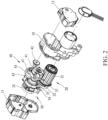
FIG. 2 is a rough exploded view of the present invention. -
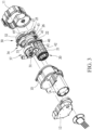
FIG. 3 is a rough exploded view of the present invention taken from a different perspective. -
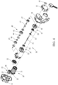
FIG. 4 is a detailed exploded view of the present invention. -
FIG. 5 is an end view of an interior of the present invention in an assembled condition. -
FIG. 6 is a cross-sectional view of the present invention, taken along line A-A ofFIG. 5 . -
FIG. 7 is a cross-sectional view of the present invention, taken along line B-B ofFIG. 5 . -
FIG. 8 is a top view, in a sectioned form, of the present invention in a home position. -
FIG. 9 is a top view, in a sectioned form, of the present invention in a first speed-up position. -
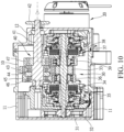
FIG. 10 is a top view, in a sectioned form, of the present invention in a second speed-up position. - A structure of the present invention is shown in
FIGS. 1 ,2 , and3 , and comprises adrive assembly 20, aninput assembly 30 and anoutput assembly 40 arranged in an interior of acasing 10. - A detailed structure of a preferred embodiment is illustrated in
FIGS. 3 ,4 ,5 ,6 , and7 . Thecasing 10 is provided with afirst end cover 11 and asecond end cover 12 respectively mounted to two ends thereof to protect and support thedrive assembly 20, theinput assembly 30 and theoutput assembly 40 of which axes are arranged in parallel. - The
drive assembly 20 comprises anelectrical motor 21. Theelectrical motor 21 has an output shaft that comprises adrive wheel 22 that drives theinput assembly 30. Thedrive wheel 22 is set in mating and transmitting engagement with theinput assembly 30 by means of a gearratio adjusting assembly 25. Further, the gearratio adjusting assembly 25 comprises afirst gear 26 and asecond gear 27 that are coaxial and are rotatable in synchronization with each other, wherein thefirst gear 26 is in mating engagement with thedrive wheel 22 of theelectrical motor 21. - The
input assembly 30 comprises atransmission shaft 31 that is parallel with an axis of thedrive wheel 22 of thedrive assembly 20, as shown inFIGS. 4 and6 . An end of thetransmission shaft 31 is provided with a drivenwheel 32 fixedly mounted thereto to be driven by thedrive wheel 22. The drivenwheel 32 is in mating engagement with thesecond gear 27 of the gearratio adjusting assembly 25, so that a rotational speed of theinput assembly 30 driven by thedrive assembly 20 is variable by varying a gear ratio of the first andsecond gears transmission shaft 31 of theinput assembly 30 is provided with aninitial transmission wheel 33 mounted to a middle section thereof to drive theoutput assembly 40, and a first speed-change assembly 34 and a second speed-change assembly 37 are respectively arranged at two opposite sides of theinitial transmission wheel 33, wherein the first speed-change assembly 34 comprises afirst clutch 35 mounted on thetransmission shaft 31, and thefirst clutch 35 comprises afirst transmission wheel 36 that is mounted on thetransmission shaft 31 and is selectively drivable; and the second speed-change assembly 37 arranged on the other side comprises asecond clutch 38 mounted on thetransmission shaft 31, and thesecond clutch 38 comprises asecond transmission wheel 39 that is mounted on thetransmission shaft 31 and is selectively drivable. - The
output assembly 40 comprises anoutput shaft 41 that is arranged parallel with an axis of thetransmission shaft 31 of theinput assembly 30, as shown inFIGS. 4 and7 . At least one of two ends of theoutput shaft 41 is extended out of an end of thecasing 10 and is provided with anoutput wheel 42, which drives an external driven member, such as a chain (not shown in the drawings). Theoutput shaft 41 is provided with an initial drivenwheel 43 mounted to a middle section thereof and in mating engagement with theinitial transmission wheel 33 of theinput assembly 30, and a first speed-change wheel 45 and a second speed-change wheel 47 are respectively arranged on two opposite sides of the initial drivenwheel 43, wherein the first speed-change wheel 45 is in mating engagement with thefirst transmission wheel 36 of thetransmission shaft 31, and the second speed-change wheel 47 is in mating engagement with thesecond transmission wheel 39 of thetransmission shaft 31. The initial drivenwheel 43 and the first speed-change wheel 45 are arranged on theoutput shaft 41 by means of a first one-way bearing 44 and a second one-way bearing 46, respectively, wherein the first one-way bearing 44 and the second one-way bearing 46 are both one-way elements that are lockable for driving in a same direction. Further, a rotational speed generated by means of a gear ratio between thefirst transmission wheel 36 of the first speed-change assembly 34 and the first speed-change wheel 45 of theoutput shaft 41 is higher than a rotational speed generated by means of a gear ratio between theinitial transmission wheel 33 and the initial drivenwheel 43, and a rotational speed generated by means of a gear ratio between thesecond transmission wheel 39 of the second speed-change assembly 37 and the second speed-change wheel 47 of theoutput shaft 41 is higher than the rotational speed generated by means of the gear ratio between theinitial transmission wheel 33 and the initial drivenwheel 43, so that when theinput assembly 30 drives theoutput shaft 41 through the first speed-change assembly 34, the initial drivenwheel 43 is in idling rotation to allow transfer of power to be stable and smooth without causing any feeing of setting back. According to some embodiments, the rotational speed generated by the gear ratio between thesecond transmission wheel 39 of the second speed-change assembly 37 and the second speed-change wheel 47 of theoutput shaft 41 is higher than the rotational speed generated by the gear ratio between thefirst transmission wheel 36 of the first speed-change assembly 34 and the first speed-change wheel 45, so that when theinput assembly 30 drives theoutput shaft 41 through the second speed-change assembly 37, the first speed-change wheel 45 and the initial drivenwheel 43 are both in idling rotation to allow transfer of power to be stable and smooth without causing any feeing of setting back. - As such, the first speed-
change assembly 34 and the second speed-change assembly 37 arranged between theinput assembly 30 and theoutput assembly 40 are individually operable to cause an increase or step-up on the initial rotational speed outputted from thedrive assembly 20, so as to achieve an effect of three-stage speed change. Further, since the first and second end covers 11, 12 on the two sides of thecasing 10 are set to respectively correspond to the first speed-change assembly 34 and the second speed-change assembly 37 of theinput assembly 30, so that assembling/disassembling and servicing of the first speed-change assembly 34 and the second speed-change assembly 37 can be enhanced, and as such, a three-stage speed-change mechanism having a simple structure and easy to maintain is realized. - To practically operate the present invention, at the beginning when the initial rotational speed is adopted, as shown in
FIGS. 2 ,4 , and8 , thedrive wheel 22 of theelectrical motor 21 of thedrive assembly 20 drives, by means of the gearratio adjusting assembly 25, thetransmission shaft 31 of theinput assembly 30 to rotate with the initial rotational speed, and the first andsecond clutches change assemblies transmission shaft 31 are not activated to get engaged, so that the first andsecond transmission wheels change assemblies transmission shaft 31, and consequently, only theinitial transmission wheel 33 on thetransmission shaft 31 is being driven to thereby drive the initial drivenwheel 43 on theoutput shaft 41 of theoutput assembly 40 in mating engagement therewith, and the initial drivenwheel 43 drives theoutput shaft 41 through the first one-way bearing 44 to have theoutput shaft 41 driven by theelectrical motor 21 to drive theoutput wheel 42 to rotate with the initial rotational speed. - To go into the first step-up position during the
output shaft 41 of theoutput assembly 40 being in rotation with the initial rotational speed, as shown inFIG. 9 , when thedrive wheel 22 of theelectrical motor 21 of thedrive assembly 20 drives, by means of the gearratio adjusting assembly 25, thetransmission shaft 31 of theinput assembly 30 to rotate with the initial rotational speed, thefirst clutch 35 of the first speed-change assembly 34 arranged on thetransmission shaft 31 is activated to get engaged, while thesecond clutch 38 of the second speed-change assembly 37 arranged on thetransmission shaft 31 is still not activated to get engaged, so that thefirst transmission wheel 36 of the first speed-change assembly 34 is driven by thetransmission shaft 31, and since the gear ratio between thefirst transmission wheel 36 of the first speed-change assembly 34 and the first speed-change wheel 45 is greater than that between theinitial transmission wheel 33 and the initial drivenwheel 43, the rotational speed of the first speed-change wheel 45 is higher than that of the initial drivenwheel 43, and thus, the first speed-change wheel 45 drives theoutput shaft 41 through the second one-way bearing 46, and reversed idling rotation is induced between theoutput shaft 41 and the first one-way bearing 44 of the initial drivenwheel 43 so as to make the initial drivenwheel 43 not interfering with theoutput shaft 41, and theoutput shaft 41 is driven by theelectrical motor 21 via the first speed-change assembly 34 to drive theoutput wheel 42 to operate with the rotational speed of the first step-up position. Further, since the rotational speed of theoutput shaft 41 is changed from the initial rotational speed toward the first step-up rotational speed, a difference of rotational speed is relatively small, so that the transfer of power is made smooth and stable and no feeling of setting back may develop. - To go into the second step-up position during the
output shaft 41 of theoutput assembly 40 being in rotation with the first step-up speed, as shown inFIG. 10 , when thedrive wheel 22 of theelectrical motor 21 of thedrive assembly 20 drives, by means of the gearratio adjusting assembly 25, thetransmission shaft 31 of theinput assembly 30, and the first speed-change assembly 34 drives theoutput shaft 41 to rotate with the first step-up rotational speed, thesecond clutch 38 of the second speed-change assembly 37 arranged on thetransmission shaft 31 is activated to get engaged, so that thesecond transmission wheel 39 of the second speed-change assembly 37 is driven by thetransmission shaft 31, and since the gear ratio between thesecond transmission wheel 39 of the second speed-change assembly 37 and the second speed-change wheel 47 is greater than the gear ratio between thefirst transmission wheel 36 of the first speed-change assembly 34 and the first speed-change wheel 45 and that between theinitial transmission wheel 33 and the initial drivenwheel 43, the rotational speed of the second speed-change wheel 47 is higher than those of the first speed-change wheel 45 and the initial drivenwheel 43, and thus, the second speed-change wheel 47 drives theoutput shaft 41, and reversed idling rotation is induced between theoutput shaft 41 and the second one-way bearing 46 of the first speed-change wheel 45 and also the first one-way bearing 44 of the initial drivenwheel 43 so as to make the first speed-change wheel 45 and the initial drivenwheel 43 not interfering with theoutput shaft 41, and theoutput shaft 41 is driven by theelectrical motor 21 via the second speed-change assembly 37 to drive theoutput wheel 42 to operate with the rotational speed of the second step-up position. Further, since the rotational speed of theoutput shaft 41 is changed from the first step-up rotational speed toward the second step-up rotational speed, a difference of rotational speed is relatively small, so that the transfer of power is made smooth and stable and no feeling of setting back may develop. - Based on the design and illustration discussed above, the present invention provides that the
initial transmission wheel 33 is arranged on a middle section of thetransmission shaft 31 of theinput assembly 30, and the first speed-change assembly 34 and the second speed-change assembly 37 are arranged on thetransmission shaft 31 respectively at two opposite sides of theinitial transmission wheel 33, and that the first one-way bearing 44 provided on the initial drivenwheel 43 and the second one-way bearing 46 provided on the first speed-change wheel 45 are both one-way elements that are lockable for driving in a same direction, in combination with the arrangement of the first and second end covers 11, 12 on the two sides of thecasing 10, so that in addition to a three-stage speed-change function achievable with the present invention, the step-by-step speed increase makes the transfer of power smooth and stable, without developing any feeling of setting back. Further, the first and second speed-change assemblies 34, 37 are respectively arranged at two sides of thetransmission shaft 31, so that the structure is made simple and assembling/disassembling and servicing can be conducted by opening the first and second end covers 11, 12 on the two sides of thecasing 10, so that there is no need to disassembling the entire device, and thus easiness of mounting and servicing can be greatly improved.
Claims (6)
- A three-stage speed-change mechanism, comprising:a drive assembly (20), which comprises an electrical motor (21), the electrical motor (21) having an output shaft that comprises a drive wheel (22) that drives an input assembly (30);the input assembly (30), which comprises a transmission shaft (31) driven by the drive wheel (22), an initial transmission wheel (33) being mounted on a middle section of the transmission shaft (31), a first speed-change assembly (34) and a second speed-change assembly (37) being respectively arranged at two opposite sides of the initial transmission wheel (33), wherein the first speed-change assembly (34) comprises a first clutch (35) arranged on the transmission shaft (31), the first clutch (35) being provided with a first transmission wheel (36) that is arranged on the transmission shaft (31) and is selectively drivable; and the second speed-change assembly (37) arranged on the opposite side comprises a second clutch (38) arranged on the transmission shaft (31), the second clutch (38) being provided with a second transmission wheel (39) that is arranged on the transmission shaft (31) and is selectively drivable; andan output assembly (40), which comprises an output shaft (41) that is arranged parallel with an axis of the transmission shaft (31) of the input assembly (30), the output shaft (41) being provided, on a middle section thereof, with an initial driven wheel (43) in mating engagement with the initial transmission wheel (33), a first speed-change wheel (45) and a second speed-change wheel (47) being respectively arranged on two opposite sides of the initial driven wheel (43), wherein the first speed-change wheel (45) is in mating engagement with the first transmission wheel (36), and the second speed-change wheel (47) is in mating engagement with the second transmission wheel (39), and the initial driven wheel (43) is mounted by means of a first one-way bearing (44) on the output shaft (41), and the first speed-change wheel (45) is mounted by means of a second one-way bearing (46) on the output shaft (41), wherein the first one-way bearing (44) and the second one-way bearing (46) are one-way elements that are lockable for driving in a same direction, and a rotational speed generated by means of a gear ratio between the first transmission wheel (36) of the first speed-change assembly (34) and the first speed-change wheel (45) is higher than a rotational speed generated by means of a gear ratio between the initial transmission wheel (33) and the initial driven wheel (43), and a rotational speed generated by means of a gear ratio between the second transmission wheel (39) of the second speed-change assembly (37) and the second speed-change wheel (47) is higher than the rotational speed generated by means of the gear ratio between the initial transmission wheel (33) and the initial driven wheel (43).
- The three-stage speed-change mechanism according to claim 1, wherein the drive assembly (20), the input assembly (30), and the output assembly (40) are arranged in an interior of a casing (10), and a first end cover (11) and a second end cover (12) that are selectively removable are respectively mounted to two ends of the casing (10).
- The three-stage speed-change mechanism according to claim 1, wherein an end of the transmission shaft (31) of the input assembly (30) is provided with a driven wheel (32) fixedly mounted thereto to be driven by the drive wheel (22).
- The three-stage speed-change mechanism according to claim 3, wherein the drive wheel (22) of the drive assembly (20) is set in mating and transmitting engagement with the driven wheel (32) of the input assembly (30) by means of a gear ratio adjusting assembly (25), and the gear ratio adjusting assembly (25) comprises a first gear (26) and a second gear (27) that are coaxial and are rotatable in synchronization with each other, wherein the first gear (26) is in mating engagement with the drive wheel (22), and the second gear (27) is in mating engagement with the driven wheel (32), so that an initial rotational speed that the drive assembly (20) drives the input assembly (30) is variable by varying a gear ratio of the first and second gears (26, 27).
- The three-stage speed-change mechanism according to claim 1, wherein at least one of two ends of the output shaft (41) of the output assembly (40) is provided with an output wheel (42), which is adapted to drive an external driven element.
- The three-stage speed-change mechanism according to claim 1, wherein the rotational speed generated by means of the gear ratio between the second transmission wheel (39) of the second speed-change assembly (37) and the second speed-change wheel (47) of the output assembly (40) is higher than the rotational speed generated by means of the gear ratio between the first transmission wheel (36) of the first speed-change assembly (34) and the first speed-change wheel (45) of the output assembly (40).
Applications Claiming Priority (1)
| Application Number | Priority Date | Filing Date | Title |
|---|---|---|---|
| TW111101115A TWI806349B (en) | 2022-01-11 | 2022-01-11 | Three-stage transmission mechanism |
Publications (3)
| Publication Number | Publication Date |
|---|---|
| EP4209693A1 true EP4209693A1 (en) | 2023-07-12 |
| EP4209693C0 EP4209693C0 (en) | 2025-07-30 |
| EP4209693B1 EP4209693B1 (en) | 2025-07-30 |
Family
ID=84888545
Family Applications (1)
| Application Number | Title | Priority Date | Filing Date |
|---|---|---|---|
| EP23150640.3A Active EP4209693B1 (en) | 2022-01-11 | 2023-01-09 | Three-stage speed-change mechanism |
Country Status (5)
| Country | Link |
|---|---|
| US (1) | US11988269B2 (en) |
| EP (1) | EP4209693B1 (en) |
| JP (2) | JP7808830B2 (en) |
| CN (2) | CN116428319A (en) |
| TW (1) | TWI806349B (en) |
Families Citing this family (1)
| Publication number | Priority date | Publication date | Assignee | Title |
|---|---|---|---|---|
| TWI806349B (en) * | 2022-01-11 | 2023-06-21 | 姚立和 | Three-stage transmission mechanism |
Citations (7)
| Publication number | Priority date | Publication date | Assignee | Title |
|---|---|---|---|---|
| CN102336136A (en) * | 2011-09-21 | 2012-02-01 | 同济大学 | Active transmission device of transversely-placed front-wheel drive vehicle |
| KR20150116635A (en) * | 2014-04-08 | 2015-10-16 | 최형진 | Power transmitter of two, three and multistage stage for cars |
| EP3459774A1 (en) * | 2017-09-20 | 2019-03-27 | Toyota Jidosha Kabushiki Kaisha | Electric vehicle |
| EP3738815A1 (en) * | 2018-04-04 | 2020-11-18 | Jing-Jin Electric Technologies Co., Ltd | Dual-power source dual-drive assembly for vehicle |
| EP3778283A1 (en) * | 2018-06-07 | 2021-02-17 | Jing-Jin Electric Technologies Co., Ltd. | Electric drive powertrain having vertically-positioned multi-stage gearboxes |
| EP3815944A1 (en) * | 2019-10-31 | 2021-05-05 | BRUSA Elektronik AG | Compact powertrain with an electric motor |
| DE102020117152B3 (en) * | 2020-06-30 | 2021-08-05 | Schaeffler Technologies AG & Co. KG | Drive train with a two-speed transmission for an electrically drivable motor vehicle |
Family Cites Families (21)
| Publication number | Priority date | Publication date | Assignee | Title |
|---|---|---|---|---|
| CH144380A (en) * | 1929-11-01 | 1930-12-31 | Mounoud Jules | Gear switch. |
| JPS56143651U (en) * | 1980-03-28 | 1981-10-29 | ||
| JP2943610B2 (en) * | 1994-06-24 | 1999-08-30 | トヨタ自動車株式会社 | Transmission control device for vehicle transmission |
| CN102403836A (en) * | 2010-09-14 | 2012-04-04 | 何良智 | Flexible control on-off shift motor for electric automobile |
| CN202201123U (en) * | 2011-07-29 | 2012-04-25 | 余成泰 | Automatic speed-changing driving device of electric vehicle |
| TWM431245U (en) * | 2012-02-01 | 2012-06-11 | You-Chun Lin | Transmission device |
| DE102012015863A1 (en) * | 2012-08-06 | 2014-05-15 | Getrag Getriebe- Und Zahnradfabrik Hermann Hagenmeyer Gmbh & Cie Kg | Multi-step transmission for a motor vehicle |
| JP6226115B2 (en) * | 2013-05-28 | 2017-11-08 | パナソニックIpマネジメント株式会社 | Electric assist bicycle |
| KR101791010B1 (en) * | 2015-09-15 | 2017-10-27 | (주)엠비아이 | Transmission for motor |
| DE102015116537B4 (en) * | 2015-09-30 | 2022-10-20 | Dr. Ing. H.C. F. Porsche Aktiengesellschaft | Electric axle drive for a motor vehicle |
| KR20170047453A (en) * | 2015-10-22 | 2017-05-08 | 현대자동차주식회사 | Transmission for vehicles |
| CN105299153B (en) * | 2015-10-29 | 2018-05-11 | 吉林大学 | The double shift transmissions of electric vehicle |
| JP6515017B2 (en) * | 2015-11-27 | 2019-05-15 | 株式会社シマノ | Bicycle drive unit |
| KR101952775B1 (en) * | 2017-04-28 | 2019-02-27 | 이엠티씨 주식회사 | The two-speed transmission |
| JP6487491B2 (en) * | 2017-05-12 | 2019-03-20 | ヤマハ発動機株式会社 | Electric vehicle and power transmission device thereof |
| DE112018006005T5 (en) * | 2017-11-24 | 2020-08-13 | Panasonic Intellectual Property Management Co., Ltd. | Drive unit of an electric assisted bicycle and an electric assisted bicycle |
| TWI665399B (en) * | 2018-05-16 | 2019-07-11 | 財團法人工業技術研究院 | Dual-shaft gearbox mechanism |
| CN108730430A (en) * | 2018-06-14 | 2018-11-02 | 江苏信息职业技术学院 | Electric vehicle automatic gear-box |
| CN112455222A (en) * | 2019-09-06 | 2021-03-09 | 舍弗勒技术股份两合公司 | Compact bridge driving system |
| TWI749582B (en) * | 2020-06-09 | 2021-12-11 | 姚立和 | Transmission structure |
| TWI806349B (en) * | 2022-01-11 | 2023-06-21 | 姚立和 | Three-stage transmission mechanism |
-
2022
- 2022-01-11 TW TW111101115A patent/TWI806349B/en active
-
2023
- 2023-01-06 CN CN202310018534.6A patent/CN116428319A/en active Pending
- 2023-01-06 CN CN202320041463.7U patent/CN219413419U/en active Active
- 2023-01-09 EP EP23150640.3A patent/EP4209693B1/en active Active
- 2023-01-09 US US18/094,395 patent/US11988269B2/en active Active
- 2023-01-10 JP JP2023002017A patent/JP7808830B2/en active Active
- 2023-01-10 JP JP2023000053U patent/JP3241178U/en active Active
Patent Citations (7)
| Publication number | Priority date | Publication date | Assignee | Title |
|---|---|---|---|---|
| CN102336136A (en) * | 2011-09-21 | 2012-02-01 | 同济大学 | Active transmission device of transversely-placed front-wheel drive vehicle |
| KR20150116635A (en) * | 2014-04-08 | 2015-10-16 | 최형진 | Power transmitter of two, three and multistage stage for cars |
| EP3459774A1 (en) * | 2017-09-20 | 2019-03-27 | Toyota Jidosha Kabushiki Kaisha | Electric vehicle |
| EP3738815A1 (en) * | 2018-04-04 | 2020-11-18 | Jing-Jin Electric Technologies Co., Ltd | Dual-power source dual-drive assembly for vehicle |
| EP3778283A1 (en) * | 2018-06-07 | 2021-02-17 | Jing-Jin Electric Technologies Co., Ltd. | Electric drive powertrain having vertically-positioned multi-stage gearboxes |
| EP3815944A1 (en) * | 2019-10-31 | 2021-05-05 | BRUSA Elektronik AG | Compact powertrain with an electric motor |
| DE102020117152B3 (en) * | 2020-06-30 | 2021-08-05 | Schaeffler Technologies AG & Co. KG | Drive train with a two-speed transmission for an electrically drivable motor vehicle |
Also Published As
| Publication number | Publication date |
|---|---|
| TW202327930A (en) | 2023-07-16 |
| JP7808830B2 (en) | 2026-01-30 |
| EP4209693C0 (en) | 2025-07-30 |
| EP4209693B1 (en) | 2025-07-30 |
| CN219413419U (en) | 2023-07-25 |
| US20230220906A1 (en) | 2023-07-13 |
| US11988269B2 (en) | 2024-05-21 |
| TWI806349B (en) | 2023-06-21 |
| JP3241178U (en) | 2023-03-09 |
| CN116428319A (en) | 2023-07-14 |
| JP2023102283A (en) | 2023-07-24 |
Similar Documents
| Publication | Publication Date | Title |
|---|---|---|
| EP2333374B1 (en) | Electric motor driving device | |
| US9638292B1 (en) | CVT differential | |
| US9068633B2 (en) | Continuous transmission system | |
| EP3234408B1 (en) | Continuously variable transmission | |
| JPH10266948A (en) | Tandem type pump with auxiliary pump | |
| US6261198B1 (en) | Continuously variable transmission | |
| EP3284971B1 (en) | Single shaft two-speed drive system | |
| US11988269B2 (en) | Three-stage speed-change mechanism | |
| EP4160047A2 (en) | Gearing assemblies and apparatus | |
| KR101422135B1 (en) | Automatic transmission | |
| EP3922884B1 (en) | Structure of speed changer | |
| EP0086534A1 (en) | Transmission, in particular for a motor vehicle | |
| US12196290B2 (en) | Speed reducer having self-locking function without ring gear, and self-locking method of speed reducer | |
| EP4040014A1 (en) | Transmission system for transmitting a speed and torque of a motor to a wheel assembly and method for transmitting a speed and torque of a motor to a wheel assembly | |
| EP3971447B1 (en) | Planetary speed-change mechanism | |
| EP2834536B1 (en) | Multi-ratio planetary gear transmission | |
| JPS6174963A (en) | Power transmission equipped with torque converter | |
| US5474504A (en) | Asymmetric planetary gear variable speed transmission | |
| KR20250030621A (en) | Mecanum wheel driving device using forward and reverse rotation device composed of gear and clutch | |
| US7568992B1 (en) | Self-adjusting positive engagement continuous variable transmission | |
| WO2004040168A1 (en) | Stepless speed change apparatus | |
| KR100896496B1 (en) | Continuously variable transmission | |
| US20140235396A1 (en) | Transmission | |
| KR20040077028A (en) | A stepless transmission | |
| NO20240929A1 (en) | Pedally propelled vehicle drive system |
Legal Events
| Date | Code | Title | Description |
|---|---|---|---|
| PUAI | Public reference made under article 153(3) epc to a published international application that has entered the european phase |
Free format text: ORIGINAL CODE: 0009012 |
|
| STAA | Information on the status of an ep patent application or granted ep patent |
Free format text: STATUS: REQUEST FOR EXAMINATION WAS MADE |
|
| 17P | Request for examination filed |
Effective date: 20230315 |
|
| AK | Designated contracting states |
Kind code of ref document: A1 Designated state(s): AL AT BE BG CH CY CZ DE DK EE ES FI FR GB GR HR HU IE IS IT LI LT LU LV MC ME MK MT NL NO PL PT RO RS SE SI SK SM TR |
|
| GRAP | Despatch of communication of intention to grant a patent |
Free format text: ORIGINAL CODE: EPIDOSNIGR1 |
|
| STAA | Information on the status of an ep patent application or granted ep patent |
Free format text: STATUS: GRANT OF PATENT IS INTENDED |
|
| INTG | Intention to grant announced |
Effective date: 20250228 |
|
| GRAS | Grant fee paid |
Free format text: ORIGINAL CODE: EPIDOSNIGR3 |
|
| GRAA | (expected) grant |
Free format text: ORIGINAL CODE: 0009210 |
|
| STAA | Information on the status of an ep patent application or granted ep patent |
Free format text: STATUS: THE PATENT HAS BEEN GRANTED |
|
| AK | Designated contracting states |
Kind code of ref document: B1 Designated state(s): AL AT BE BG CH CY CZ DE DK EE ES FI FR GB GR HR HU IE IS IT LI LT LU LV MC ME MK MT NL NO PL PT RO RS SE SI SK SM TR |
|
| REG | Reference to a national code |
Ref country code: GB Ref legal event code: FG4D |
|
| REG | Reference to a national code |
Ref country code: CH Ref legal event code: EP |
|
| REG | Reference to a national code |
Ref country code: DE Ref legal event code: R096 Ref document number: 602023005086 Country of ref document: DE |
|
| REG | Reference to a national code |
Ref country code: IE Ref legal event code: FG4D |
|
| U01 | Request for unitary effect filed |
Effective date: 20250806 |
|
| U07 | Unitary effect registered |
Designated state(s): AT BE BG DE DK EE FI FR IT LT LU LV MT NL PT RO SE SI Effective date: 20250819 |
|
| PG25 | Lapsed in a contracting state [announced via postgrant information from national office to epo] |
Ref country code: IS Free format text: LAPSE BECAUSE OF FAILURE TO SUBMIT A TRANSLATION OF THE DESCRIPTION OR TO PAY THE FEE WITHIN THE PRESCRIBED TIME-LIMIT Effective date: 20251130 |
|
| PG25 | Lapsed in a contracting state [announced via postgrant information from national office to epo] |
Ref country code: NO Free format text: LAPSE BECAUSE OF FAILURE TO SUBMIT A TRANSLATION OF THE DESCRIPTION OR TO PAY THE FEE WITHIN THE PRESCRIBED TIME-LIMIT Effective date: 20251030 |
|
| PG25 | Lapsed in a contracting state [announced via postgrant information from national office to epo] |
Ref country code: HR Free format text: LAPSE BECAUSE OF FAILURE TO SUBMIT A TRANSLATION OF THE DESCRIPTION OR TO PAY THE FEE WITHIN THE PRESCRIBED TIME-LIMIT Effective date: 20250730 |
|
| PG25 | Lapsed in a contracting state [announced via postgrant information from national office to epo] |
Ref country code: GR Free format text: LAPSE BECAUSE OF FAILURE TO SUBMIT A TRANSLATION OF THE DESCRIPTION OR TO PAY THE FEE WITHIN THE PRESCRIBED TIME-LIMIT Effective date: 20251031 |
|
| PG25 | Lapsed in a contracting state [announced via postgrant information from national office to epo] |
Ref country code: PL Free format text: LAPSE BECAUSE OF FAILURE TO SUBMIT A TRANSLATION OF THE DESCRIPTION OR TO PAY THE FEE WITHIN THE PRESCRIBED TIME-LIMIT Effective date: 20250730 |
|
| PG25 | Lapsed in a contracting state [announced via postgrant information from national office to epo] |
Ref country code: RS Free format text: LAPSE BECAUSE OF FAILURE TO SUBMIT A TRANSLATION OF THE DESCRIPTION OR TO PAY THE FEE WITHIN THE PRESCRIBED TIME-LIMIT Effective date: 20251030 |
|
| PG25 | Lapsed in a contracting state [announced via postgrant information from national office to epo] |
Ref country code: ES Free format text: LAPSE BECAUSE OF FAILURE TO SUBMIT A TRANSLATION OF THE DESCRIPTION OR TO PAY THE FEE WITHIN THE PRESCRIBED TIME-LIMIT Effective date: 20250730 |
|
| PG25 | Lapsed in a contracting state [announced via postgrant information from national office to epo] |
Ref country code: SM Free format text: LAPSE BECAUSE OF FAILURE TO SUBMIT A TRANSLATION OF THE DESCRIPTION OR TO PAY THE FEE WITHIN THE PRESCRIBED TIME-LIMIT Effective date: 20250730 |
|
| PG25 | Lapsed in a contracting state [announced via postgrant information from national office to epo] |
Ref country code: CZ Free format text: LAPSE BECAUSE OF FAILURE TO SUBMIT A TRANSLATION OF THE DESCRIPTION OR TO PAY THE FEE WITHIN THE PRESCRIBED TIME-LIMIT Effective date: 20250730 |
|
| PG25 | Lapsed in a contracting state [announced via postgrant information from national office to epo] |
Ref country code: SK Free format text: LAPSE BECAUSE OF FAILURE TO SUBMIT A TRANSLATION OF THE DESCRIPTION OR TO PAY THE FEE WITHIN THE PRESCRIBED TIME-LIMIT Effective date: 20250730 |
|
| PLBE | No opposition filed within time limit |
Free format text: ORIGINAL CODE: 0009261 |
|
| STAA | Information on the status of an ep patent application or granted ep patent |
Free format text: STATUS: NO OPPOSITION FILED WITHIN TIME LIMIT |
|
| REG | Reference to a national code |
Ref country code: CH Ref legal event code: L10 Free format text: ST27 STATUS EVENT CODE: U-0-0-L10-L00 (AS PROVIDED BY THE NATIONAL OFFICE) Effective date: 20260611 |
|
| 26N | No opposition filed |
Effective date: 20260501 |
|
| U21 | Renewal fee for the european patent with unitary effect paid with additional fee |
Year of fee payment: 4 Effective date: 20260708 |