EP4209692A1 - Damper apparatus - Google Patents
Damper apparatus Download PDFInfo
- Publication number
- EP4209692A1 EP4209692A1 EP21864254.4A EP21864254A EP4209692A1 EP 4209692 A1 EP4209692 A1 EP 4209692A1 EP 21864254 A EP21864254 A EP 21864254A EP 4209692 A1 EP4209692 A1 EP 4209692A1
- Authority
- EP
- European Patent Office
- Prior art keywords
- support surface
- rotor
- load support
- cone spring
- bush
- Prior art date
- Legal status (The legal status is an assumption and is not a legal conclusion. Google has not performed a legal analysis and makes no representation as to the accuracy of the status listed.)
- Pending
Links
Images



Classifications
-
- F—MECHANICAL ENGINEERING; LIGHTING; HEATING; WEAPONS; BLASTING
- F16—ENGINEERING ELEMENTS AND UNITS; GENERAL MEASURES FOR PRODUCING AND MAINTAINING EFFECTIVE FUNCTIONING OF MACHINES OR INSTALLATIONS; THERMAL INSULATION IN GENERAL
- F16F—SPRINGS; SHOCK-ABSORBERS; MEANS FOR DAMPING VIBRATION
- F16F15/00—Suppression of vibrations in systems; Means or arrangements for avoiding or reducing out-of-balance forces, e.g. due to motion
- F16F15/10—Suppression of vibrations in rotating systems by making use of members moving with the system
- F16F15/12—Suppression of vibrations in rotating systems by making use of members moving with the system using elastic members or friction-damping members, e.g. between a rotating shaft and a gyratory mass mounted thereon
- F16F15/129—Suppression of vibrations in rotating systems by making use of members moving with the system using elastic members or friction-damping members, e.g. between a rotating shaft and a gyratory mass mounted thereon characterised by friction-damping means
- F16F15/1292—Suppression of vibrations in rotating systems by making use of members moving with the system using elastic members or friction-damping members, e.g. between a rotating shaft and a gyratory mass mounted thereon characterised by friction-damping means characterised by arrangements for axially clamping or positioning or otherwise influencing the frictional plates
-
- F—MECHANICAL ENGINEERING; LIGHTING; HEATING; WEAPONS; BLASTING
- F16—ENGINEERING ELEMENTS AND UNITS; GENERAL MEASURES FOR PRODUCING AND MAINTAINING EFFECTIVE FUNCTIONING OF MACHINES OR INSTALLATIONS; THERMAL INSULATION IN GENERAL
- F16F—SPRINGS; SHOCK-ABSORBERS; MEANS FOR DAMPING VIBRATION
- F16F15/00—Suppression of vibrations in systems; Means or arrangements for avoiding or reducing out-of-balance forces, e.g. due to motion
- F16F15/10—Suppression of vibrations in rotating systems by making use of members moving with the system
- F16F15/12—Suppression of vibrations in rotating systems by making use of members moving with the system using elastic members or friction-damping members, e.g. between a rotating shaft and a gyratory mass mounted thereon
- F16F15/131—Suppression of vibrations in rotating systems by making use of members moving with the system using elastic members or friction-damping members, e.g. between a rotating shaft and a gyratory mass mounted thereon the rotating system comprising two or more gyratory masses
- F16F15/139—Suppression of vibrations in rotating systems by making use of members moving with the system using elastic members or friction-damping members, e.g. between a rotating shaft and a gyratory mass mounted thereon the rotating system comprising two or more gyratory masses characterised by friction-damping means
- F16F15/1392—Suppression of vibrations in rotating systems by making use of members moving with the system using elastic members or friction-damping members, e.g. between a rotating shaft and a gyratory mass mounted thereon the rotating system comprising two or more gyratory masses characterised by friction-damping means characterised by arrangements for axially clamping or positioning or otherwise influencing the frictional plates
Definitions
- the present invention relates to a damper apparatus to be disposed, for example, between an internal combustion engine and a transmission.
- Patent Document 1 discloses a damper apparatus of such kind that includes an input-side rotor, an output-side rotor, and coil springs, wherein: the input-side rotor receives torque inputted from an internal combustion engine; the output-side rotor is combined with the input-side rotor so as to be relatively rotatable with respect to the input-side rotor; and the coil springs are disposed between the input-side rotor and the output-side rotor, and are arranged such that each of the coil springs extends along a tangential line of rotation.
- the damper apparatus disclosed in Patent Document 1 further includes a friction generation mechanism structured to generate frictional torque in response to relative rotation between the input-side rotor and the output-side rotor.
- the friction generation mechanism includes a spline hub serving as the output-side rotor, a bush being in sliding contact with the spline hub, and an annular cone spring biasing the bush in an axial direction.
- Patent Document 1 has a tapered cross section with a relatively small inclination, and is inclined so as to include an inner periphery axially adjacent to the bush and an outer periphery axially adjacent to a retention plate. These configurations may cause the cone spring to be turned over into a taper orientation reversed with respect to the original one in case that, for example, the spline hub receives an enormous load in the axial direction and is displaced to flatten the cone spring. In other words, Patent Document 1 fails to consider such turning over phenomenon upon setting a position of a point of action of a pressing force exerted from the retention plate to the cone spring and a position of a point of action of an opposite pressing force exerted from the bush to the cone spring.
- Patent Document 1 JP 2003-074636 A
- a damper apparatus may include: a first rotor; a second rotor; a spring connecting the first rotor and the second rotor elastically; and a friction generation mechanism structured to generate frictional torque in response to relative rotation between the first rotor and the second rotor.
- the friction generation mechanism may include: a bush being in contact with an annular friction surface of the second rotor; a retention plate that is a part of the first rotor, and faces the bush in an axial direction; and a cone spring that has an annular shape, and is disposed between the bush and the retention plate so as to be compressed, and biases the bush toward the annular friction surface of the second rotor.
- the bush includes a first load support surface being in contact with an inner periphery of the cone spring, while the retention plate includes a second load support surface being in contact with an outer periphery of the cone spring, wherein the first load support surface and the second load support surface face each other.
- the first load support surface and the second load support surface respectively include a first step part and a second step part that are retracted in the axial direction so as to respectively accept the outer periphery and the inner periphery of the cone spring in case that the cone spring is installed at a reversed orientation.
- the first step part of the first load support surface has a boundary that is positioned outer in a radial direction, with respect to a boundary of the second step part of the second load support surface.
- the bush includes a first load support surface being in contact with an inner periphery of the cone spring, while the retention plate includes a second load support surface being in contact with an outer periphery of the cone spring, wherein the first load support surface and the second load support surface face each other.
- the first load support surface includes a first step part that is retracted in the axial direction so as to accept the outer periphery of the cone spring in case that the cone spring is installed at a reversed orientation.
- the first step part of the first load support surface has a boundary that is positioned outer in a radial direction, with respect to an inner peripheral edge of the second load support surface being flat.
- the bush includes a first load support surface being in contact with an outer periphery of the cone spring, while the retention plate includes a second load support surface being in contact with an inner periphery of the cone spring, wherein the first load support surface and the second load support surface face each other.
- the first load support surface and the second load support surface respectively include a first step part and a second step part that are retracted in the axial direction so as to respectively accept the inner periphery and the outer periphery of the cone spring in case that the cone spring is installed at a reversed orientation.
- the first step part of the first load support surface has a boundary that is positioned inner in a radial direction, with respect to a boundary of the second step part of the second load support surface.
- the bush includes a first load support surface being in contact with an outer periphery of the cone spring, while the retention plate includes a second load support surface being in contact with an inner periphery of the cone spring, wherein the first load support surface and the second load support surface face each other.
- the first load support surface includes a first step part that is retracted in the axial direction so as to accept the inner periphery of the cone spring in case that the cone spring is installed at a reversed orientation.
- the first step part of the first load support surface has a boundary that is positioned in a radial direction within a radial range of the second load support surface being flat.
- the cone spring is sandwiched by flat sections of the first load support surface and the second load support surface, even if the cone spring is flatten due to an excessive load in the axial direction. This suppresses the cone spring from receiving a moment to reverse a taper of the cone spring from an original orientation into a reversed orientation, and thereby avoids turning over of the cone spring.
- FIG. 1 shows a friction generation mechanism 1 according to the first embodiment which is a focused part of a damper apparatus according to the present invention.
- An overall appearance of the damper apparatus is known as disclosed in Patent Document 1 etc., and is omitted in the present drawings.
- the damper apparatus includes an input-side rotor 2 mounted to a flywheel of an internal combustion engine and structured to receive torque from the internal combustion engine and an output-side rotor 3 combined with input-side rotor 2 relatively rotatably with respect to input-side rotor 2.
- Output-side rotor 3 includes in its rotational center a spline hub 4 structured to be in spline coupling with an input shaft of a transmission.
- Spline hub 4 includes a boss part 4a having a cylindrical shape and a disc part 4b spreading radially outwardly from an axially central part of boss part 4a.
- a left side in FIG. 1 faces the internal combustion engine, and a right side in FIG. 1 faces the transmission.
- Input-side rotor 2 has a disc shape composed of a retention plate 5 being substantially circular and facing the transmission and a cover plate (not shown) being substantially circular and facing the internal combustion engine, wherein an outer periphery of retention plate 5 and an outer periphery of the cover plate are joined to each other.
- Retention plate 5 and the cover plate interpose therebetween disc part 4b of spline hub 4 being a part of output-side rotor 3.
- Disc part 4b and input-side rotor 2 interpose therebetween a plurality of (e.g. four) coil springs not shown that are arranged along tangential lines of rotation and connect disc part 4b and input-side rotor 2 elastically in a rotational direction thereof. The coil springs exert elastic force and thereby absorb torsional vibration.
- Each of retention plate 5 and the cover plate not shown is formed by press-forming a metallic plate.
- FIG. 1 shows only an inner circumferential part of retention plate 5.
- Friction generation mechanism 1 is structured to generate frictional torque serving as damping force, in response to relative rotation between input-side rotor 2 and output-side rotor 3.
- Friction generation mechanism 1 includes a bush 6 and a cone spring 7.
- Bush 6 has an annular shape, and is made of a hard synthetic resin such as a so-called engineering plastic.
- Cone spring 7 has an annular shape, and is disposed between bush 6 and retention plate 5 so as to be compressed.
- Bush 6 is rotatably fitted to an outer periphery of boss part 4a of spline hub 4, and includes a back face including an annular friction surface 6a being in contact with an annular friction surface 4c of disc part 4b of spline hub 4. Annular friction surface 6a and annular friction surface 4c spread along a plane orthogonal to a rotational central axis, and are in sliding contact with each other to generate the frictional torque.
- Bush 6 further includes a cylindrical part 6b extending toward the transmission, and has an substantially L-shaped cross section as a whole. Cylindrical part 6b includes an outer periphery to which cone spring 7 is fitted, and determines a radial position of cone spring 7.
- Retention plate 5 includes the inner circumferential part facing bush 6 in the axial direction so as to interpose cone spring 7 therebetween.
- the inner circumferential part of retention plate 5 includes an end positioned in a slightly outer circumferential side with respect to cylindrical part 6b of bush 6.
- the end of retention plate 5 and cylindrical part 6b of bush 6 partially overlap with each other in the axial direction.
- Cone spring 7 has a tapered cross section inclined at a relatively small angle with respect to a plane perpendicular to the axial direction. According to the first embodiment, cone spring 7 is inclined at an orientation set such that an inner periphery 7a of cone spring 7 is axially nearer to bush 6 than to retention plate 5 while an outer periphery 7b of cone spring 7 is axially nearer to retention plate 5 than to bush 6. Furthermore, as shown in FIG. 2 , which is a plan view of cone spring 7 according to the first embodiment, inner periphery 7a of cone spring 7 has a continuous circular shape, while outer periphery 7b of cone spring 7 includes indentations 8 and has an uneven shape.
- Bush 6 includes a first load support surface 9 being in contact with inner periphery 7a of cone spring 7.
- First load support surface 9 spreads perpendicularly to an inner peripheral surface of cylindrical part 6b of bush 6 and parallelly with a plane perpendicular to the axial direction.
- Retention plate 5 includes a second load support surface 10 being in contact with outer periphery 7b of cone spring 7.
- Second load support surface 10 spreads parallelly with a plane perpendicular to the axial direction.
- First load support surface 9 and second load support surface 10 face each other in the axial direction.
- First load support surface 9 includes a step part 9a that is retracted in the axial direction so as to accept outer periphery 7b of cone spring 7 in case that cone spring 7 is wrongly installed at a reversed orientation.
- Step part 9a is positioned in an outer circumferential part of bush 6, and does not contact with cone spring 7 under regular conditions. Accordingly, what substantially serves as first load support surface 9 is a flat surface part 9b formed in an inner circumferential part of first load support surface 9 separately from step part 9a.
- second load support surface 10 includes a step part 10a that is retracted in the axial direction so as to accept inner periphery 7a of cone spring 7 in case that cone spring 7 is wrongly installed at the reversed orientation.
- Step part 10a is formed by drawing an inner peripheral edge of retention plate 5 made from a metallic plate. Step part 10a does not contact with cone spring 7 under regular conditions. Accordingly, what substantially serves as second load support surface 10 is a flat surface part 10b formed in an outer circumferential part of second load support surface 10 separately from step part 10a.
- step part 9a of first load support surface 9 has a boundary 9c positioned outer in a radial direction, with respect to a boundary 10c of step part 10a of second load support surface 10.
- a radius D1 to boundary 9c of first load support surface 9 is greater than a radius D2 to boundary 10c of second load support surface 10.
- flat surface part 9b and flat surface part 10b overlap with each other through a certain radial width, wherein flat surface part 9b is formed in the inner circumferential part of first load support surface 9 and substantially serves as first load support surface 9, and wherein flat surface part 10b is formed in the outer circumferential part of second load support surface 10 and substantially serves as second load support surface 10.
- friction generation mechanism 1 is configured such that cone spring 7 including outer periphery 7b supported by retention plate 5 biases bush 6 toward disc part 4b in the axial direction. This causes annular friction surface 6a and annular friction surface 4c to be in appropriate press contact with each other.
- Step part 9a of first load support surface 9 and step part 10a of second load support surface 10 contribute to an inspection process for detecting wrong installation of cone spring 7 in which cone spring 7 is installed in the reversed orientation.
- FIG. 3 shows a state in which cone spring 7 is wrongly installed at the reversed orientation. In this state, cone spring 7 is tapered reversely in comparison with the regular attitude, and outer periphery 7b enters step part 9a, and inner periphery 7a enters step part 10a. This greatly reduces the force axially biasing cone spring 7, as is obvious in comparison with FIG. 1 . This allows the wrong installation to be easily detected by measuring the friction torque of friction generation mechanism 1 after assembling the damper apparatus.
- outer periphery 7b having the uneven shape is in contact with retention plate 5 made of a metal, while inner periphery 7a having the smoothly continuous circular shape is in contact with bush 6 made of a synthetic resin.
- outer periphery 7b having the uneven shape is in contact with bush 6 made of a synthetic resin. This deteriorates the apparatus in durability. Therefore, the wrong installation has to be inspected and eliminated after assembly.
- cone spring 7 is installed at the reversed orientation between first load support surface 9 and second load support surface 10 without step part 9a and step part 10a, it is difficult to detect the wrong installation on the basis of the friction torque because the biasing force is approximately equal to that in case of the regular orientation.
- step part 9a and step part 10a might cause a phenomenon of turning over the taper of cone spring 7 from the regular orientation into the reversed orientation in case that cone spring 7 receives an excessive load in the axial direction.
- the first embodiment is configured to satisfy the relation of D1 > D2 as described above. This suppresses cone spring 7 from undergoing the turning over even if cone spring 7 receives an excessive load in the axial direction.
- cone spring 7 is merely sandwiched and compressed in a region between radius D1 and radius D2 by first load support surface 9 and second load support surface 10 (i.e., flat surface part 9b and flat surface part 10b) that are parallel with each other and are both parallel with a plane perpendicular to the axial direction. Accordingly, cone spring 7 does not receive a moment to turn over cone spring 7. This effect is further explained in the following with reference to the second embodiment.
- FIG. 4 shows the second embodiment of friction generation mechanism 1.
- the second embodiment is configured such that first load support surface 9 of bush 6 includes step part 9a structured to accept outer periphery 7b of cone spring 7 in case that cone spring 7 is wrongly installed at the reversed orientation.
- second load support surface 10 of retention plate 5 does not include step part 10a shown in the first embodiment.
- second load support surface 10 according to the second embodiment is flat all the way to its inner peripheral edge 10d facing a vicinity of inner periphery 7a of cone spring 7.
- Boundary 9c of step part 9a of first load support surface 9 is positioned radially outer with respect to inner peripheral edge 10d of second load support surface 10.
- a radius D3 to boundary 9c of first load support surface 9 is greater than a radius D4 to inner peripheral edge 10d of second load support surface 10.
- step part 9a of first load support surface 9 allows outer periphery 7b of cone spring 7 to enter step part 9a, and greatly reduces the axial biasing force on cone spring 7, in case that cone spring 7 is wrongly installed at the reversed orientation. This facilitates detection of the wrong installation in the inspection process.
- the second embodiment satisfies the relation of D3 > D4, and thereby, similarly to the first embodiment, serves to avoid the turning over of cone spring 7 in response to an axial excessive load.
- FIGs. 5A to 5C illustrate a mechanism for avoiding the turning over of cone spring 7 in response to an axial load, which takes the second embodiment for example.
- FIG. 5B shows a neutral state with no axial load.
- cone spring 7 is approximately flat because cone spring 7 is compressed in an initial state after installation thereof.
- FIG. 5A shows a state in which spline hub 4 is receiving an axial load to the left side of the drawing as shown by an arrow therein, wherein spline hub 4 is a part of output-side rotor 3 while retention plate 5 is a part of input-side rotor 2.
- the axial load in this direction has no effect to cause the turning over of cone spring 7.
- FIG. 5C shows a state in which spline hub 4 of output-side rotor 3 is receiving an axial load to the right side of the drawing as shown by an arrow therein.
- inner periphery 7a of cone spring 7 is pressed to the right side of the drawing, while outer periphery 7b of cone spring 7 is pressed to the left side of the drawing.
- cone spring 7 is sandwiched and compressed by first load support surface 9 (in detail, flat surface part 9b) and second load support surface 10 that overlap with each other and are both flat. Accordingly, cone spring 7 does not receive a moment to turn over cone spring 7.
- FIGs. 6A to 6C illustrate the turning over of cone spring 7 as a comparative example.
- This comparative example corresponds to a case of, for example, inverting the relation between radius D1 and radius D2 in the first embodiment in FIG. 1 into a relation of D1 ⁇ D2.
- boundary 9c of step part 9a of first load support surface 9 is positioned in the inner circumferential side with respect to boundary 10c of step part 10a of second load support surface 10.
- FIG. 6B shows a neutral state with no axial load.
- FIG. 6A shows a state in which spline hub 4 is receiving an axial load to the left side of the drawing as shown by an arrow therein, wherein spline hub 4 is the part of output-side rotor 3 while retention plate 5 is the part of input-side rotor 2.
- FIG. 6C shows a state in which spline hub 4 of output-side rotor 3 is receiving an axial load to the right side of the drawing as shown by an arrow therein. If the considerable axial load is exerted in the direction shown in FIG. 6C , inner periphery 7a of cone spring 7 is pressed to the right side of the drawing, while outer periphery 7b of cone spring 7 is pressed to the left side of the drawing.
- a force pressing cone spring 7 to the right side of the drawing has a point of action positioned in the inner circumferential side with respect to a point of action of a force pressing cone spring 7 to the left side of the drawing. This generates a moment to bring the taper of cone spring 7 to a reversed state beyond a flat state, and may turn over cone spring 7 as shown in the drawing. Furthermore, the turning over of cone spring 7 often causes a crack.
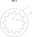
- cone spring 7 has a tapered cross section inclined inversely with respect to the first and second embodiments. Furthermore, as shown in FIG. 8 , cone spring 7 according to the third embodiment includes outer periphery 7b having a continuous circular shape and inner periphery 7a including indentations 8 and having an uneven shape.
- Bush 6 includes first load support surface 9 structured to be in contact with outer periphery 7b of cone spring 7.
- Retention plate 5 includes second load support surface 10 structured to be in contact with inner periphery 7a of cone spring 7.
- First load support surface 9 and second load support surface 10 are both parallel with a plane perpendicular to the axial direction, and face each other in the axial direction.
- First load support surface 9 includes, in its inner circumferential side, step part 9a that is retracted in the axial direction so as to accept inner periphery 7a of cone spring 7 in case that cone spring 7 is wrongly installed at a reversed orientation. Step part 9a does not contact with cone spring 7 under regular conditions. Accordingly, what substantially serves as first load support surface 9 is flat surface part 9b formed in an outer circumferential part of first load support surface 9 separately from step part 9a.
- second load support surface 10 includes, in its outer peripheral part, step part 10a that is retracted in the axial direction so as to accept outer periphery 7b of cone spring 7 in case that cone spring 7 is wrongly installed at a reversed orientation.
- Step part 10a does not contact with cone spring 7 under regular conditions.
- what substantially serves as second load support surface 10 is flat surface part 10b formed in an inner circumferential part of second load support surface 10 separately from step part 10a.
- Boundary 9c of step part 9a of first load support surface 9 is positioned radially inner with respect to boundary 10c of step part 10a of second load support surface 10. In other words, as shown in FIG. 7 , a radius D5 to boundary 9c of first load support surface 9 is less than a radius D6 to boundary 10c of second load support surface 10.
- flat surface part 9b and flat surface part 10b overlap with each other through a certain radial width, wherein flat surface part 9b is formed in the outer circumferential part of first load support surface 9 and substantially serves as first load support surface 9, and wherein flat surface part 10b is formed in the inner circumferential part of second load support surface 10 and substantially serves as second load support surface 10.
- the third embodiment is configured to allow inner periphery 7a and outer periphery 7b of cone spring 7 to respectively enter step part 9a and step part 10a, and greatly reduce the force biasing cone spring 7, in case that cone spring 7 is wrongly installed at the reversed orientation. This facilitates detection of abnormality in the inspection process.
- the third embodiment serves to suppress generation of a moment to turn over the orientation of the taper because the third embodiment satisfies the relation of D5 ⁇ D6. This suppresses cone spring 7 from undergoing the turning over, similarly to the first and second embodiments.
- inner periphery 7a of cone spring 7 having the uneven shape is in contact with retention plate 5 made of a metal.
- FIG. 9 shows the fourth embodiment of friction generation mechanism 1.
- the fourth embodiment is configured to form step part 9a in an inner circumferential part of first load support surface 9 of bush 6 so as to accept inner periphery 7a of cone spring 7 in case that cone spring 7 is wrongly installed at the reversed orientation.
- second load support surface 10 of retention plate 5 does not include step part 10a shown in the third embodiment.
- second load support surface 10 according to the fourth embodiment is flat all the way from inner peripheral edge 10d to a part facing a vicinity of outer periphery 7b of cone spring 7.
- Boundary 9c of step part 9a of first load support surface 9 is radially positioned within a radial range of second load support surface 10 being flat. Accordingly, when viewing first load support surface 9 and second load support surface 10 at a projection view in the axial direction, flat surface part 9b overlaps with second load support surface 10 being flat, wherein flat surface part 9b is formed in an outer circumferential part of first load support surface 9 and substantially serves as first load support surface 9.
- step part 9a of first load support surface 9 allows inner periphery 7a of cone spring 7 to enter step part 9a, and greatly reduces the axial biasing force on cone spring 7, in case that cone spring 7 is wrongly installed at the reversed orientation. This facilitates detection of the wrong installation in the inspection process.
- flat surface part 9b in the outer circumferential part of first load support surface 9 is radially positioned to overlap with second load support surface 10 being flat. This serves to avoid the turning over of cone spring 7 in response to an axial excessive load, similarly to the third embodiment.
Landscapes
- Engineering & Computer Science (AREA)
- General Engineering & Computer Science (AREA)
- Physics & Mathematics (AREA)
- Acoustics & Sound (AREA)
- Aviation & Aerospace Engineering (AREA)
- Mechanical Engineering (AREA)
- Mechanical Operated Clutches (AREA)
- Springs (AREA)
- Support Of The Bearing (AREA)
Abstract
Description
- The present invention relates to a damper apparatus to be disposed, for example, between an internal combustion engine and a transmission.
- An automobile often includes a damper apparatus disposed between an internal combustion engine and a transmission and structured to transfer torque while absorbing and damping torsional vibration. Patent Document 1 discloses a damper apparatus of such kind that includes an input-side rotor, an output-side rotor, and coil springs, wherein: the input-side rotor receives torque inputted from an internal combustion engine; the output-side rotor is combined with the input-side rotor so as to be relatively rotatable with respect to the input-side rotor; and the coil springs are disposed between the input-side rotor and the output-side rotor, and are arranged such that each of the coil springs extends along a tangential line of rotation.
- The damper apparatus disclosed in Patent Document 1 further includes a friction generation mechanism structured to generate frictional torque in response to relative rotation between the input-side rotor and the output-side rotor. The friction generation mechanism includes a spline hub serving as the output-side rotor, a bush being in sliding contact with the spline hub, and an annular cone spring biasing the bush in an axial direction.
- The cone spring in Patent Document 1 has a tapered cross section with a relatively small inclination, and is inclined so as to include an inner periphery axially adjacent to the bush and an outer periphery axially adjacent to a retention plate. These configurations may cause the cone spring to be turned over into a taper orientation reversed with respect to the original one in case that, for example, the spline hub receives an enormous load in the axial direction and is displaced to flatten the cone spring. In other words, Patent Document 1 fails to consider such turning over phenomenon upon setting a position of a point of action of a pressing force exerted from the retention plate to the cone spring and a position of a point of action of an opposite pressing force exerted from the bush to the cone spring.
- Patent Document 1:
JP 2003-074636 A - According to the present invention, a damper apparatus may include: a first rotor; a second rotor; a spring connecting the first rotor and the second rotor elastically; and a friction generation mechanism structured to generate frictional torque in response to relative rotation between the first rotor and the second rotor. The friction generation mechanism may include: a bush being in contact with an annular friction surface of the second rotor; a retention plate that is a part of the first rotor, and faces the bush in an axial direction; and a cone spring that has an annular shape, and is disposed between the bush and the retention plate so as to be compressed, and biases the bush toward the annular friction surface of the second rotor.
- According to a first aspect, the bush includes a first load support surface being in contact with an inner periphery of the cone spring, while the retention plate includes a second load support surface being in contact with an outer periphery of the cone spring, wherein the first load support surface and the second load support surface face each other. The first load support surface and the second load support surface respectively include a first step part and a second step part that are retracted in the axial direction so as to respectively accept the outer periphery and the inner periphery of the cone spring in case that the cone spring is installed at a reversed orientation. The first step part of the first load support surface has a boundary that is positioned outer in a radial direction, with respect to a boundary of the second step part of the second load support surface.
- According to a second aspect, the bush includes a first load support surface being in contact with an inner periphery of the cone spring, while the retention plate includes a second load support surface being in contact with an outer periphery of the cone spring, wherein the first load support surface and the second load support surface face each other. The first load support surface includes a first step part that is retracted in the axial direction so as to accept the outer periphery of the cone spring in case that the cone spring is installed at a reversed orientation. The first step part of the first load support surface has a boundary that is positioned outer in a radial direction, with respect to an inner peripheral edge of the second load support surface being flat.
- According to a third aspect, the bush includes a first load support surface being in contact with an outer periphery of the cone spring, while the retention plate includes a second load support surface being in contact with an inner periphery of the cone spring, wherein the first load support surface and the second load support surface face each other. The first load support surface and the second load support surface respectively include a first step part and a second step part that are retracted in the axial direction so as to respectively accept the inner periphery and the outer periphery of the cone spring in case that the cone spring is installed at a reversed orientation. The first step part of the first load support surface has a boundary that is positioned inner in a radial direction, with respect to a boundary of the second step part of the second load support surface.
- According to a fourth aspect, the bush includes a first load support surface being in contact with an outer periphery of the cone spring, while the retention plate includes a second load support surface being in contact with an inner periphery of the cone spring, wherein the first load support surface and the second load support surface face each other. The first load support surface includes a first step part that is retracted in the axial direction so as to accept the inner periphery of the cone spring in case that the cone spring is installed at a reversed orientation. The first step part of the first load support surface has a boundary that is positioned in a radial direction within a radial range of the second load support surface being flat.
- According to the above configurations, the cone spring is sandwiched by flat sections of the first load support surface and the second load support surface, even if the cone spring is flatten due to an excessive load in the axial direction. This suppresses the cone spring from receiving a moment to reverse a taper of the cone spring from an original orientation into a reversed orientation, and thereby avoids turning over of the cone spring.
-
-
FIG. 1 is a sectional view of a focused part of a friction generation mechanism according to a first embodiment of the present invention. -
FIG. 2 is a plan view of a cone spring according to the first embodiment. -
FIG. 3 is a sectional view in case that the cone spring is installed at a reversed orientation. -
FIG. 4 is a sectional view of a focused part of a friction generation mechanism according to a second embodiment of the present invention. -
FIGs. 5A to 5C are illustrative views of the friction generation mechanism according to the second embodiment when receiving axial loads. -
FIGs. 6A to 6C are illustrative views of a friction generation mechanism according to a comparative example when receiving axial loads. -
FIG. 7 is a sectional view of a focused part of a friction generation mechanism according to a third embodiment of the present invention. -
FIG. 8 is a plan view of a cone spring according to the third embodiment. -
FIG. 9 is a sectional view of a focused part of a friction generation mechanism according to a fourth embodiment of the present invention. - The following details the first embodiment of the present invention, with reference to the drawings.
-
FIG. 1 shows a friction generation mechanism 1 according to the first embodiment which is a focused part of a damper apparatus according to the present invention. An overall appearance of the damper apparatus is known as disclosed in Patent Document 1 etc., and is omitted in the present drawings. The damper apparatus includes an input-side rotor 2 mounted to a flywheel of an internal combustion engine and structured to receive torque from the internal combustion engine and an output-side rotor 3 combined with input-side rotor 2 relatively rotatably with respect to input-side rotor 2. Output-side rotor 3 includes in its rotational center aspline hub 4 structured to be in spline coupling with an input shaft of a transmission.Spline hub 4 includes aboss part 4a having a cylindrical shape and adisc part 4b spreading radially outwardly from an axially central part ofboss part 4a. Incidentally, a left side inFIG. 1 faces the internal combustion engine, and a right side inFIG. 1 faces the transmission. - Input-
side rotor 2 has a disc shape composed of aretention plate 5 being substantially circular and facing the transmission and a cover plate (not shown) being substantially circular and facing the internal combustion engine, wherein an outer periphery ofretention plate 5 and an outer periphery of the cover plate are joined to each other.Retention plate 5 and the cover plate interposetherebetween disc part 4b ofspline hub 4 being a part of output-side rotor 3.Disc part 4b and input-side rotor 2 interpose therebetween a plurality of (e.g. four) coil springs not shown that are arranged along tangential lines of rotation and connectdisc part 4b and input-side rotor 2 elastically in a rotational direction thereof. The coil springs exert elastic force and thereby absorb torsional vibration. Each ofretention plate 5 and the cover plate not shown is formed by press-forming a metallic plate.FIG. 1 shows only an inner circumferential part ofretention plate 5. - Friction generation mechanism 1 is structured to generate frictional torque serving as damping force, in response to relative rotation between input-
side rotor 2 and output-side rotor 3. Friction generation mechanism 1 includes abush 6 and acone spring 7. Bush 6 has an annular shape, and is made of a hard synthetic resin such as a so-called engineering plastic. Conespring 7 has an annular shape, and is disposed betweenbush 6 andretention plate 5 so as to be compressed. - Bush 6 is rotatably fitted to an outer periphery of
boss part 4a ofspline hub 4, and includes a back face including anannular friction surface 6a being in contact with anannular friction surface 4c ofdisc part 4b ofspline hub 4.Annular friction surface 6a andannular friction surface 4c spread along a plane orthogonal to a rotational central axis, and are in sliding contact with each other to generate the frictional torque. Bush 6 further includes acylindrical part 6b extending toward the transmission, and has an substantially L-shaped cross section as a whole.Cylindrical part 6b includes an outer periphery to whichcone spring 7 is fitted, and determines a radial position ofcone spring 7. -
Retention plate 5 includes the inner circumferentialpart facing bush 6 in the axial direction so as to interposecone spring 7 therebetween. The inner circumferential part ofretention plate 5 includes an end positioned in a slightly outer circumferential side with respect tocylindrical part 6b ofbush 6. Thus, the end ofretention plate 5 andcylindrical part 6b ofbush 6 partially overlap with each other in the axial direction. -
Cone spring 7 has a tapered cross section inclined at a relatively small angle with respect to a plane perpendicular to the axial direction. According to the first embodiment,cone spring 7 is inclined at an orientation set such that aninner periphery 7a ofcone spring 7 is axially nearer tobush 6 than toretention plate 5 while anouter periphery 7b ofcone spring 7 is axially nearer toretention plate 5 than tobush 6. Furthermore, as shown inFIG. 2 , which is a plan view ofcone spring 7 according to the first embodiment,inner periphery 7a ofcone spring 7 has a continuous circular shape, whileouter periphery 7b ofcone spring 7 includesindentations 8 and has an uneven shape. -
Bush 6 includes a firstload support surface 9 being in contact withinner periphery 7a ofcone spring 7. Firstload support surface 9 spreads perpendicularly to an inner peripheral surface ofcylindrical part 6b ofbush 6 and parallelly with a plane perpendicular to the axial direction.Retention plate 5 includes a secondload support surface 10 being in contact withouter periphery 7b ofcone spring 7. Secondload support surface 10 spreads parallelly with a plane perpendicular to the axial direction. Firstload support surface 9 and secondload support surface 10 face each other in the axial direction. - First
load support surface 9 includes astep part 9a that is retracted in the axial direction so as to acceptouter periphery 7b ofcone spring 7 in case thatcone spring 7 is wrongly installed at a reversed orientation. Steppart 9a is positioned in an outer circumferential part ofbush 6, and does not contact withcone spring 7 under regular conditions. Accordingly, what substantially serves as firstload support surface 9 is aflat surface part 9b formed in an inner circumferential part of firstload support surface 9 separately fromstep part 9a. - Similarly, second
load support surface 10 includes astep part 10a that is retracted in the axial direction so as to acceptinner periphery 7a ofcone spring 7 in case thatcone spring 7 is wrongly installed at the reversed orientation. Steppart 10a is formed by drawing an inner peripheral edge ofretention plate 5 made from a metallic plate. Steppart 10a does not contact withcone spring 7 under regular conditions. Accordingly, what substantially serves as secondload support surface 10 is aflat surface part 10b formed in an outer circumferential part of secondload support surface 10 separately fromstep part 10a. - As shown in
FIG. 1 ,step part 9a of firstload support surface 9 has aboundary 9c positioned outer in a radial direction, with respect to aboundary 10c ofstep part 10a of secondload support surface 10. In other words, a radius D1 toboundary 9c of firstload support surface 9 is greater than a radius D2 toboundary 10c of secondload support surface 10. Accordingly, when viewing firstload support surface 9 and secondload support surface 10 at a projection view in the axial direction,flat surface part 9b andflat surface part 10b overlap with each other through a certain radial width, whereinflat surface part 9b is formed in the inner circumferential part of firstload support surface 9 and substantially serves as firstload support surface 9, and whereinflat surface part 10b is formed in the outer circumferential part of secondload support surface 10 and substantially serves as secondload support surface 10. - Thus, friction generation mechanism 1 is configured such that
cone spring 7 includingouter periphery 7b supported byretention plate 5biases bush 6 towarddisc part 4b in the axial direction. This causesannular friction surface 6a andannular friction surface 4c to be in appropriate press contact with each other. - Step
part 9a of firstload support surface 9 and steppart 10a of secondload support surface 10 contribute to an inspection process for detecting wrong installation ofcone spring 7 in whichcone spring 7 is installed in the reversed orientation.FIG. 3 shows a state in whichcone spring 7 is wrongly installed at the reversed orientation. In this state,cone spring 7 is tapered reversely in comparison with the regular attitude, andouter periphery 7b entersstep part 9a, andinner periphery 7a entersstep part 10a. This greatly reduces the force axially biasingcone spring 7, as is obvious in comparison withFIG. 1 . This allows the wrong installation to be easily detected by measuring the friction torque of friction generation mechanism 1 after assembling the damper apparatus. - In the state of
FIG. 1 in whichcone spring 7 is installed at the regular orientation,outer periphery 7b having the uneven shape is in contact withretention plate 5 made of a metal, whileinner periphery 7a having the smoothly continuous circular shape is in contact withbush 6 made of a synthetic resin. In the state ofFIG. 3 in whichcone spring 7 is installed at the reversed orientation,outer periphery 7b having the uneven shape is in contact withbush 6 made of a synthetic resin. This deteriorates the apparatus in durability. Therefore, the wrong installation has to be inspected and eliminated after assembly. Ifcone spring 7 is installed at the reversed orientation between firstload support surface 9 and secondload support surface 10 withoutstep part 9a and steppart 10a, it is difficult to detect the wrong installation on the basis of the friction torque because the biasing force is approximately equal to that in case of the regular orientation. - The configuration of forming
step part 9a and steppart 10a might cause a phenomenon of turning over the taper ofcone spring 7 from the regular orientation into the reversed orientation in case thatcone spring 7 receives an excessive load in the axial direction. However, the first embodiment is configured to satisfy the relation of D1 > D2 as described above. This suppressescone spring 7 from undergoing the turning over even ifcone spring 7 receives an excessive load in the axial direction. In detail, even if receiving such excessive axial load,cone spring 7 is merely sandwiched and compressed in a region between radius D1 and radius D2 by firstload support surface 9 and second load support surface 10 (i.e.,flat surface part 9b andflat surface part 10b) that are parallel with each other and are both parallel with a plane perpendicular to the axial direction. Accordingly,cone spring 7 does not receive a moment to turn overcone spring 7. This effect is further explained in the following with reference to the second embodiment. -
FIG. 4 shows the second embodiment of friction generation mechanism 1. The following omits explanation overlapping with that in the first embodiment. Similarly to the first embodiment, the second embodiment is configured such that firstload support surface 9 ofbush 6 includesstep part 9a structured to acceptouter periphery 7b ofcone spring 7 in case thatcone spring 7 is wrongly installed at the reversed orientation. On the other hand, secondload support surface 10 ofretention plate 5 does not includestep part 10a shown in the first embodiment. Thus, secondload support surface 10 according to the second embodiment is flat all the way to its innerperipheral edge 10d facing a vicinity ofinner periphery 7a ofcone spring 7. -
Boundary 9c ofstep part 9a of firstload support surface 9 is positioned radially outer with respect to innerperipheral edge 10d of secondload support surface 10. In other words, a radius D3 toboundary 9c of firstload support surface 9 is greater than a radius D4 to innerperipheral edge 10d of secondload support surface 10. Accordingly, when viewing firstload support surface 9 and secondload support surface 10 at a projection view in the axial direction,flat surface part 9b and secondload support surface 10 overlap with each other through a certain radial width, whereinflat surface part 9b is formed in the inner circumferential part of firstload support surface 9 and substantially serves as firstload support surface 9, and wherein secondload support surface 10 is flat. - Even such configuration of forming
only step part 9a of firstload support surface 9 allowsouter periphery 7b ofcone spring 7 to enterstep part 9a, and greatly reduces the axial biasing force oncone spring 7, in case thatcone spring 7 is wrongly installed at the reversed orientation. This facilitates detection of the wrong installation in the inspection process. - Furthermore, the second embodiment satisfies the relation of D3 > D4, and thereby, similarly to the first embodiment, serves to avoid the turning over of
cone spring 7 in response to an axial excessive load. -
FIGs. 5A to 5C illustrate a mechanism for avoiding the turning over ofcone spring 7 in response to an axial load, which takes the second embodiment for example.FIG. 5B shows a neutral state with no axial load. In this example,cone spring 7 is approximately flat becausecone spring 7 is compressed in an initial state after installation thereof.FIG. 5A shows a state in whichspline hub 4 is receiving an axial load to the left side of the drawing as shown by an arrow therein, whereinspline hub 4 is a part of output-side rotor 3 whileretention plate 5 is a part of input-side rotor 2. The axial load in this direction has no effect to cause the turning over ofcone spring 7. -
FIG. 5C shows a state in whichspline hub 4 of output-side rotor 3 is receiving an axial load to the right side of the drawing as shown by an arrow therein. In this state,inner periphery 7a ofcone spring 7 is pressed to the right side of the drawing, whileouter periphery 7b ofcone spring 7 is pressed to the left side of the drawing. However, since the relation of D3 > D4 is satisfied,cone spring 7 is sandwiched and compressed by first load support surface 9 (in detail,flat surface part 9b) and secondload support surface 10 that overlap with each other and are both flat. Accordingly,cone spring 7 does not receive a moment to turn overcone spring 7. -
FIGs. 6A to 6C illustrate the turning over ofcone spring 7 as a comparative example. This comparative example corresponds to a case of, for example, inverting the relation between radius D1 and radius D2 in the first embodiment inFIG. 1 into a relation of D1 < D2. In this case,boundary 9c ofstep part 9a of firstload support surface 9 is positioned in the inner circumferential side with respect toboundary 10c ofstep part 10a of secondload support surface 10.FIG. 6B shows a neutral state with no axial load.FIG. 6A shows a state in whichspline hub 4 is receiving an axial load to the left side of the drawing as shown by an arrow therein, whereinspline hub 4 is the part of output-side rotor 3 whileretention plate 5 is the part of input-side rotor 2. -
FIG. 6C shows a state in whichspline hub 4 of output-side rotor 3 is receiving an axial load to the right side of the drawing as shown by an arrow therein. If the considerable axial load is exerted in the direction shown inFIG. 6C ,inner periphery 7a ofcone spring 7 is pressed to the right side of the drawing, whileouter periphery 7b ofcone spring 7 is pressed to the left side of the drawing. In this state, a force pressingcone spring 7 to the right side of the drawing has a point of action positioned in the inner circumferential side with respect to a point of action of a force pressingcone spring 7 to the left side of the drawing. This generates a moment to bring the taper ofcone spring 7 to a reversed state beyond a flat state, and may turn overcone spring 7 as shown in the drawing. Furthermore, the turning over ofcone spring 7 often causes a crack. - The following describes the third embodiment of friction generation mechanism 1. According to the third embodiment,
cone spring 7 has a tapered cross section inclined inversely with respect to the first and second embodiments. Furthermore, as shown inFIG. 8 ,cone spring 7 according to the third embodiment includesouter periphery 7b having a continuous circular shape andinner periphery 7a including indentations 8 and having an uneven shape. -
Bush 6 includes firstload support surface 9 structured to be in contact withouter periphery 7b ofcone spring 7.Retention plate 5 includes secondload support surface 10 structured to be in contact withinner periphery 7a ofcone spring 7. Firstload support surface 9 and secondload support surface 10 are both parallel with a plane perpendicular to the axial direction, and face each other in the axial direction. - First
load support surface 9 includes, in its inner circumferential side,step part 9a that is retracted in the axial direction so as to acceptinner periphery 7a ofcone spring 7 in case thatcone spring 7 is wrongly installed at a reversed orientation. Steppart 9a does not contact withcone spring 7 under regular conditions. Accordingly, what substantially serves as firstload support surface 9 isflat surface part 9b formed in an outer circumferential part of firstload support surface 9 separately fromstep part 9a. - Similarly, second
load support surface 10 includes, in its outer peripheral part,step part 10a that is retracted in the axial direction so as to acceptouter periphery 7b ofcone spring 7 in case thatcone spring 7 is wrongly installed at a reversed orientation. Steppart 10a does not contact withcone spring 7 under regular conditions. Accordingly, what substantially serves as secondload support surface 10 isflat surface part 10b formed in an inner circumferential part of secondload support surface 10 separately fromstep part 10a. -
Boundary 9c ofstep part 9a of firstload support surface 9 is positioned radially inner with respect toboundary 10c ofstep part 10a of secondload support surface 10. In other words, as shown inFIG. 7 , a radius D5 toboundary 9c of firstload support surface 9 is less than a radius D6 toboundary 10c of secondload support surface 10. Accordingly, when viewing firstload support surface 9 and secondload support surface 10 at a projection view in the axial direction,flat surface part 9b andflat surface part 10b overlap with each other through a certain radial width, whereinflat surface part 9b is formed in the outer circumferential part of firstload support surface 9 and substantially serves as firstload support surface 9, and whereinflat surface part 10b is formed in the inner circumferential part of secondload support surface 10 and substantially serves as secondload support surface 10. - Thus, also the third embodiment is configured to allow
inner periphery 7a andouter periphery 7b ofcone spring 7 to respectively enterstep part 9a and steppart 10a, and greatly reduce the force biasingcone spring 7, in case thatcone spring 7 is wrongly installed at the reversed orientation. This facilitates detection of abnormality in the inspection process. - Furthermore, even in case of receiving an excessive axial load, the third embodiment serves to suppress generation of a moment to turn over the orientation of the taper because the third embodiment satisfies the relation of D5 < D6. This suppresses
cone spring 7 from undergoing the turning over, similarly to the first and second embodiments. - In addition, according to the third embodiment,
inner periphery 7a ofcone spring 7 having the uneven shape is in contact withretention plate 5 made of a metal. -
FIG. 9 shows the fourth embodiment of friction generation mechanism 1. Similarly to the third embodiment, the fourth embodiment is configured to formstep part 9a in an inner circumferential part of firstload support surface 9 ofbush 6 so as to acceptinner periphery 7a ofcone spring 7 in case thatcone spring 7 is wrongly installed at the reversed orientation. On the other hand, secondload support surface 10 ofretention plate 5 does not includestep part 10a shown in the third embodiment. In other words, secondload support surface 10 according to the fourth embodiment is flat all the way from innerperipheral edge 10d to a part facing a vicinity ofouter periphery 7b ofcone spring 7. -
Boundary 9c ofstep part 9a of firstload support surface 9 is radially positioned within a radial range of secondload support surface 10 being flat. Accordingly, when viewing firstload support surface 9 and secondload support surface 10 at a projection view in the axial direction,flat surface part 9b overlaps with secondload support surface 10 being flat, whereinflat surface part 9b is formed in an outer circumferential part of firstload support surface 9 and substantially serves as firstload support surface 9. - Even such configuration of forming
only step part 9a of firstload support surface 9 allowsinner periphery 7a ofcone spring 7 to enterstep part 9a, and greatly reduces the axial biasing force oncone spring 7, in case thatcone spring 7 is wrongly installed at the reversed orientation. This facilitates detection of the wrong installation in the inspection process. - Furthermore,
flat surface part 9b in the outer circumferential part of firstload support surface 9 is radially positioned to overlap with secondload support surface 10 being flat. This serves to avoid the turning over ofcone spring 7 in response to an axial excessive load, similarly to the third embodiment.
Claims (7)
- A damper apparatus comprising:a first rotor;a second rotor relatively rotatable with respect to the first rotor;a spring connecting the first rotor and the second rotor elastically in a rotational direction; anda friction generation mechanism structured to generate frictional torque in response to relative rotation between the first rotor and the second rotor,wherein:the friction generation mechanism includes:a bush that has a substantially L-shaped cross section, and includes a back face being in contact with an annular friction surface of the second rotor;a retention plate that is a part of the first rotor, and faces the bush in an axial direction; anda cone spring that has an annular shape, and is disposed between the bush and the retention plate so as to be compressed, and biases the bush toward the annular friction surface of the second rotor;the bush includes a first load support surface being in contact with an inner periphery of the cone spring;the retention plate includes a second load support surface being in contact with an outer periphery of the cone spring;the first load support surface and the second load support surface face each other;the first load support surface and the second load support surface respectively include a first step part and a second step part that are retracted in the axial direction so as to respectively accept the outer periphery and the inner periphery of the cone spring in case that the cone spring is installed at a reversed orientation; andthe first step part of the first load support surface has a boundary that is positioned outer in a radial direction, with respect to a boundary of the second step part of the second load support surface.
- A damper apparatus comprising:a first rotor;a second rotor relatively rotatable with respect to the first rotor;a spring connecting the first rotor and the second rotor elastically in a rotational direction; anda friction generation mechanism structured to generate frictional torque in response to relative rotation between the first rotor and the second rotor,wherein:the friction generation mechanism includes:a bush that has a substantially L-shaped cross section, and includes a back face being in contact with an annular friction surface of the second rotor;a retention plate that is a part of the first rotor, and faces the bush in an axial direction; anda cone spring that has an annular shape, and is disposed between the bush and the retention plate so as to be compressed, and biases the bush toward the annular friction surface of the second rotor;the bush includes a first load support surface being in contact with an inner periphery of the cone spring;the retention plate includes a second load support surface being in contact with an outer periphery of the cone spring;the first load support surface and the second load support surface face each other;the first load support surface includes a first step part that is retracted in the axial direction so as to accept the outer periphery of the cone spring in case that the cone spring is installed at a reversed orientation; andthe first step part of the first load support surface has a boundary that is positioned outer in a radial direction, with respect to an inner peripheral edge of the second load support surface being flat.
- A damper apparatus comprising:a first rotor;a second rotor relatively rotatable with respect to the first rotor;a spring connecting the first rotor and the second rotor elastically in a rotational direction; anda friction generation mechanism structured to generate frictional torque in response to relative rotation between the first rotor and the second rotor,wherein:the friction generation mechanism includes:a bush that has a substantially L-shaped cross section, and includes a back face being in contact with an annular friction surface of the second rotor;a retention plate that is a part of the first rotor, and faces the bush in an axial direction; anda cone spring that has an annular shape, and is disposed between the bush and the retention plate so as to be compressed, and biases the bush toward the annular friction surface of the second rotor;the bush includes a first load support surface being in contact with an outer periphery of the cone spring;the retention plate includes a second load support surface being in contact with an inner periphery of the cone spring;the first load support surface and the second load support surface face each other;the first load support surface and the second load support surface respectively include a first step part and a second step part that are retracted in the axial direction so as to respectively accept the inner periphery and the outer periphery of the cone spring in case that the cone spring is installed at a reversed orientation; andthe first step part of the first load support surface has a boundary that is positioned inner in a radial direction, with respect to a boundary of the second step part of the second load support surface.
- A damper apparatus comprising:a first rotor;a second rotor relatively rotatable with respect to the first rotor;a spring connecting the first rotor and the second rotor elastically in a rotational direction; anda friction generation mechanism structured to generate frictional torque in response to relative rotation between the first rotor and the second rotor,wherein:the friction generation mechanism includes:a bush that has a substantially L-shaped cross section, and includes a back face being in contact with an annular friction surface of the second rotor;a retention plate that is a part of the first rotor, and faces the bush in an axial direction; anda cone spring that has an annular shape, and is disposed between the bush and the retention plate so as to be compressed, and biases the bush toward the annular friction surface of the second rotor;the bush includes a first load support surface being in contact with an outer periphery of the cone spring;the retention plate includes a second load support surface being in contact with an inner periphery of the cone spring;the first load support surface and the second load support surface face each other;the first load support surface includes a first step part that is retracted in the axial direction so as to accept the inner periphery of the cone spring in case that the cone spring is installed at a reversed orientation; andthe first step part of the first load support surface has a boundary that is positioned in a radial direction within a radial range of the second load support surface being flat.
- The damper apparatus as claimed in claim 1 or 2, wherein:the inner periphery of the cone spring has a continuous circular shape; andthe outer periphery of the cone spring includes indentations, and has an uneven shape.
- The damper apparatus as claimed in claim 3 or 4, wherein:the outer periphery of the cone spring has a continuous circular shape; andthe inner periphery of the cone spring includes indentations, and has an uneven shape.
- The damper apparatus as claimed in any one of claims 1 to 6, wherein:the bush is made of a synthetic resin; andthe retention plate is made of a metal.
Applications Claiming Priority (2)
| Application Number | Priority Date | Filing Date | Title |
|---|---|---|---|
| JP2020148674 | 2020-09-04 | ||
| PCT/JP2021/031578 WO2022050196A1 (en) | 2020-09-04 | 2021-08-27 | Damper apparatus |
Publications (2)
| Publication Number | Publication Date |
|---|---|
| EP4209692A1 true EP4209692A1 (en) | 2023-07-12 |
| EP4209692A4 EP4209692A4 (en) | 2024-06-05 |
Family
ID=80491771
Family Applications (1)
| Application Number | Title | Priority Date | Filing Date |
|---|---|---|---|
| EP21864254.4A Pending EP4209692A4 (en) | 2020-09-04 | 2021-08-27 | DAMPER DEVICE |
Country Status (5)
| Country | Link |
|---|---|
| US (1) | US12553493B2 (en) |
| EP (1) | EP4209692A4 (en) |
| JP (1) | JP7375213B2 (en) |
| CN (1) | CN115917182B (en) |
| WO (1) | WO2022050196A1 (en) |
Families Citing this family (1)
| Publication number | Priority date | Publication date | Assignee | Title |
|---|---|---|---|---|
| JPWO2024224810A1 (en) * | 2023-04-28 | 2024-10-31 |
Family Cites Families (7)
| Publication number | Priority date | Publication date | Assignee | Title |
|---|---|---|---|---|
| DE3921283A1 (en) * | 1989-02-08 | 1990-08-09 | Fichtel & Sachs Ag | CLUTCH DISC WITH TORSION VIBRATION DAMPER AND RADIAL ELASTIC BEARING |
| DE19747220C2 (en) * | 1997-10-25 | 2002-01-24 | Mannesmann Sachs Ag | Clutch disc for a motor vehicle friction clutch |
| JP3825190B2 (en) | 1998-12-15 | 2006-09-20 | 株式会社エクセディ | Friction bush |
| JP4028972B2 (en) | 2001-08-31 | 2008-01-09 | 株式会社エクセディ | Damper mechanism |
| JP2006170388A (en) | 2004-12-17 | 2006-06-29 | Exedy Corp | Friction generating mechanism |
| JP5742326B2 (en) * | 2011-03-15 | 2015-07-01 | アイシン精機株式会社 | Torque fluctuation absorber |
| JP6956047B2 (en) * | 2018-06-13 | 2021-10-27 | 本田技研工業株式会社 | Damper device |
-
2021
- 2021-08-27 JP JP2022546294A patent/JP7375213B2/en active Active
- 2021-08-27 WO PCT/JP2021/031578 patent/WO2022050196A1/en not_active Ceased
- 2021-08-27 CN CN202180051609.XA patent/CN115917182B/en active Active
- 2021-08-27 US US18/043,763 patent/US12553493B2/en active Active
- 2021-08-27 EP EP21864254.4A patent/EP4209692A4/en active Pending
Also Published As
| Publication number | Publication date |
|---|---|
| US12553493B2 (en) | 2026-02-17 |
| CN115917182A (en) | 2023-04-04 |
| EP4209692A4 (en) | 2024-06-05 |
| US20230313860A1 (en) | 2023-10-05 |
| WO2022050196A1 (en) | 2022-03-10 |
| CN115917182B (en) | 2026-05-08 |
| JPWO2022050196A1 (en) | 2022-03-10 |
| JP7375213B2 (en) | 2023-11-07 |
Similar Documents
| Publication | Publication Date | Title |
|---|---|---|
| JP5625676B2 (en) | Torque fluctuation absorber | |
| US10781882B2 (en) | Torque fluctuation absorbing apparatus | |
| JP6965566B2 (en) | Torque fluctuation absorber | |
| EP2500600A2 (en) | Torque fluctuation absorber | |
| KR100408803B1 (en) | Damper mechanism | |
| US12553493B2 (en) | Damper apparatus | |
| US6332843B1 (en) | Damper disk assembly | |
| KR20220030297A (en) | Centrifugal pendulum, torque transmission device including centrifugal pendulum, and vehicle | |
| US20150133225A1 (en) | Torsional vibration damping device | |
| JP4617845B2 (en) | Clutch disc | |
| JP5929941B2 (en) | Hysteresis mechanism of damper device for vehicles | |
| JP7429130B2 (en) | Spring seat and damper device | |
| JP2002181131A (en) | Torque transmission | |
| US20040206201A1 (en) | Flywheel assembly | |
| JP6708004B2 (en) | Damper device | |
| WO2018037971A1 (en) | Vehicular damper device | |
| KR102090398B1 (en) | Damper flywheel | |
| JP6388565B2 (en) | Torque limiter device | |
| US20250224005A1 (en) | Damper device | |
| JP7427472B2 (en) | Spring seat and damper device | |
| WO2024224810A1 (en) | Damper device | |
| JP6044531B2 (en) | Damper device | |
| JP2026080765A (en) | Power transmission device | |
| CN115929845A (en) | Curved spring stop with lead-through geometry | |
| JP2010265973A (en) | Torque limiter |
Legal Events
| Date | Code | Title | Description |
|---|---|---|---|
| STAA | Information on the status of an ep patent application or granted ep patent |
Free format text: STATUS: THE INTERNATIONAL PUBLICATION HAS BEEN MADE |
|
| PUAI | Public reference made under article 153(3) epc to a published international application that has entered the european phase |
Free format text: ORIGINAL CODE: 0009012 |
|
| STAA | Information on the status of an ep patent application or granted ep patent |
Free format text: STATUS: REQUEST FOR EXAMINATION WAS MADE |
|
| 17P | Request for examination filed |
Effective date: 20230307 |
|
| AK | Designated contracting states |
Kind code of ref document: A1 Designated state(s): AL AT BE BG CH CY CZ DE DK EE ES FI FR GB GR HR HU IE IS IT LI LT LU LV MC MK MT NL NO PL PT RO RS SE SI SK SM TR |
|
| DAV | Request for validation of the european patent (deleted) | ||
| DAX | Request for extension of the european patent (deleted) | ||
| A4 | Supplementary search report drawn up and despatched |
Effective date: 20240506 |
|
| RIC1 | Information provided on ipc code assigned before grant |
Ipc: F16F 15/129 20060101AFI20240429BHEP |