EP4209394A1 - Driving unit of a commercial vehicle with underride protection, floor assembly and commercial vehicle - Google Patents
Driving unit of a commercial vehicle with underride protection, floor assembly and commercial vehicle Download PDFInfo
- Publication number
- EP4209394A1 EP4209394A1 EP22150676.9A EP22150676A EP4209394A1 EP 4209394 A1 EP4209394 A1 EP 4209394A1 EP 22150676 A EP22150676 A EP 22150676A EP 4209394 A1 EP4209394 A1 EP 4209394A1
- Authority
- EP
- European Patent Office
- Prior art keywords
- chassis
- loading
- underrun protection
- driving position
- stop
- Prior art date
- Legal status (The legal status is an assumption and is not a legal conclusion. Google has not performed a legal analysis and makes no representation as to the accuracy of the status listed.)
- Withdrawn
Links
- 238000013016 damping Methods 0.000 claims description 11
- 239000000758 substrate Substances 0.000 claims description 2
- 230000006378 damage Effects 0.000 description 11
- 239000010410 layer Substances 0.000 description 8
- 208000027418 Wounds and injury Diseases 0.000 description 2
- 239000012792 core layer Substances 0.000 description 2
- 208000014674 injury Diseases 0.000 description 2
- 239000004033 plastic Substances 0.000 description 2
- 229920003023 plastic Polymers 0.000 description 2
- 239000000725 suspension Substances 0.000 description 2
- 229920002430 Fibre-reinforced plastic Polymers 0.000 description 1
- 230000002411 adverse Effects 0.000 description 1
- 238000010276 construction Methods 0.000 description 1
- 239000013013 elastic material Substances 0.000 description 1
- 239000011151 fibre-reinforced plastic Substances 0.000 description 1
- 238000009434 installation Methods 0.000 description 1
- 238000009413 insulation Methods 0.000 description 1
- 230000007257 malfunction Effects 0.000 description 1
- 239000002184 metal Substances 0.000 description 1
- 239000007787 solid Substances 0.000 description 1
Images

Classifications
-
- B—PERFORMING OPERATIONS; TRANSPORTING
- B60—VEHICLES IN GENERAL
- B60R—VEHICLES, VEHICLE FITTINGS, OR VEHICLE PARTS, NOT OTHERWISE PROVIDED FOR
- B60R19/00—Wheel guards; Radiator guards, e.g. grilles; Obstruction removers; Fittings damping bouncing force in collisions
- B60R19/56—Fittings damping bouncing force in truck collisions, e.g. bumpers; Arrangements on high-riding vehicles, e.g. lorries, for preventing vehicles or objects from running thereunder
Definitions
- the invention relates to a chassis group of a commercial vehicle, in particular a truck, trailer or semi-trailer, with a chassis and an underride guard assigned to the rear end of the chassis and carried by the chassis to prevent the chassis from driving under in the event of a rear-end collision, the underride guard being in a lower driving position toward the rear of the chassis and upwardly to a plurality of loading positions and back. Furthermore, the invention relates to an underbody of a commercial vehicle with a corresponding chassis group and a commercial vehicle with a corresponding underbody or with a corresponding chassis group.
- Commercial vehicles are known in different configurations, for example in the form of trucks, trailers or semi-trailers. Irrespective of their design, commercial vehicles are primarily intended for the transport of goods, ie the load to be transported, primarily on public roads.
- the commercial vehicles can have tarpaulin structures that have at least one tarpaulin for closing at least one side and/or a roof of the tarpaulin structure. If a tarpaulin can be moved along a side wall, one also speaks of so-called curtainsiders. In contrast, in so-called box bodies, the side walls and the roof are closed by solid walls.
- a door frame is provided at the rear in the form of a rear wall frame, on which two doors are held in the form of rear wall doors and in which the doors are accommodated when the doors are in the closed position.
- a front wall is provided opposite the rear wall frame. Included corresponding end walls and rear walls can be provided in the same way for tarpaulin structures and for box bodies.
- the side walls, the roof, the front wall, the floor and/or the doors can be constructed in the form of multi-layer commercial vehicle panels which comprise structuring inner cover layers, structuring outer cover layers and a core layer made of foamed plastic in between.
- the corresponding outer cover layers and inner cover layers can themselves be multi-layered if required and serve to stiffen the commercial vehicle panels, which is why the outer cover layers and inner cover layers usually have at least one layer made of a metal and/or a fiber-reinforced plastic.
- the individual commercial vehicle panels of a box body are typically connected to one another at a corner in order to form a cuboid box body that has a loading space ready for accommodating the goods to be transported.
- box bodies are also particularly suitable for the transport of temperature-sensitive goods, for example for so-called refrigerated transport.
- the same box bodies can also be used to transport moisture-sensitive goods, i.e. dry transport.
- the known commercial vehicles have a chassis and a running gear fixed to the chassis with one or more pairs of wheels.
- the wheel pairs may be associated with the front or rear end of the utility vehicle. This is mostly the case with multi-axle trailers. With semi-trailers they are Pairs of wheels, however, provided with a not inconsiderable distance to the front and to the rear end of the commercial vehicle.
- a floor structure is carried by the chassis and can provide a loading floor on which the load to be transported can be placed.
- the floor structure can carry a trough in which bulk goods can be transported. Together with a chassis group, the floor structure forms a floor assembly of the commercial vehicle.
- the chassis group includes at least the chassis and an underrun protection. In addition, the chassis group can also include the actual chassis.
- chassis groups of commercial vehicles have a rear underrun protection. This is typically required by law and is intended to prevent vehicles driving under the chassis from behind the commercial vehicle.
- an underrun protection usually has a cross member which is hit by a vehicle driving up against the commercial vehicle from behind and thus prevents the driving vehicle from getting further under the chassis. This is to avoid serious injuries to road users as far as possible. This protection is generally all the more pronounced if the underrun protection protrudes further down and can therefore be approached lower.
- the underrun protection of a commercial vehicle can touch the ground in certain situations. This is particularly the case when the utility vehicle drives up a ramp, as may be the case, for example, when loading utility vehicles onto ships. In the event of such contact, considerable forces may act on the underrun protection as a result of the not inconsiderable weight of the commercial vehicle. As a result of these forces, the underrun protection or even the chassis of the commercial vehicle can be damaged, which jeopardizes the safe operation of the commercial vehicle and can entail considerable repair costs.
- the present invention is therefore based on the object of designing and developing the chassis group, the underbody group and the commercial vehicle of the type mentioned at the outset and previously explained in more detail in such a way that the commercial vehicle can be loaded more reliably.
- an underbody of a commercial vehicle in particular a truck, trailer or semi-trailer, with a chassis group according to one of claims 1 to 13 and a loading floor extending in the longitudinal direction of the chassis above the chassis for setting up loads.
- the underrun protection can be deflected so far backwards and upwards through the contact with the ground that may occur during loading that the loading is no longer hindered.
- damage to the chassis group is avoided, which could occur if the underrun protection could not be adjusted from the lower driving position to an upper loading position.
- Contact with the ground can occur during loading of the commercial vehicles, in particular when driving onto a ramp and/or driving down a ramp, in that the underrun protection touches down on the ground.
- the underrun protection can then swerve backwards and upwards in relation to the chassis to avoid damaging the utility vehicle. In principle, this can take place independently of whether the underride protection comes into contact with an obstacle or the ground when the commercial vehicle is driving forwards or backwards.
- the underrun protection can be continuously adjusted from the driving position.
- the underrun protection can then be adjusted in essentially any number of loading positions.
- the underrun protection can always be deflected from the driving position just as far as is expedient or necessary in order to avoid the obstacle or the ground when the underrun protection comes into contact with the obstacle or the ground.
- a hold-down device which opposes a restoring force to the corresponding upward pivoting of the underrun protection, ensures that the underrun protection is deflected as far as necessary or not excessively. Otherwise, the skid plate could hit the chassis in an up position with considerable speed and damage it or the skid plate itself.
- the restoring force of the hold-down device ensures that the underrun protection returns to the lower driving position after contact with the ground, so that the actual function of the underrun protection can be carried out again immediately. This also prevents the driver from operating incorrectly, for example by forgetting to release the underride protection or to adjust the underride protection back down again.
- the at least one hold-down device is designed as a spring element.
- the required restoring force can be applied very easily, inexpensively and reliably in order to adjust the underrun protection back to the lower driving position and also to keep it there reliably. This is all the more achieved when the spring element is a gas pressure spring element, which can be very precisely adapted to the respective requirements in terms of its spring characteristic.
- the at least one hold-down device can be provided in such a way that the underrun protection can be adjusted over the entire adjustment path from the lower driving position to the loading positions, in particular to the uppermost possible loading position, against the restoring force of the at least one hold-down device.
- the underride guard returns to the lower driving position reliably and in a defined manner from any of the possible loading positions as a result of the restoring force.
- this prevents the underrun protection from being deflected upwards in an undefined and undamped manner. In this way, damage to the underrun protection or the chassis can be avoided.
- the at least one hold-down device is provided in such a way that the underrun protection can be automatically adjusted from the loading positions in the direction of the restoring force of the at least one hold-down device back into the lower driving position.
- Mandatory means that the underrun protection is automatically adjusted back to the driving position if and to the extent that the chassis moves further away from the ground, for example in a loading situation. In this context, it preferably plays no role in which of the loading positions the underrun protection is located.
- the underride guard can preferably also be automatically adjustable from the uppermost possible loading position back into the lower driving position in the direction of the restoring force of the at least one hold-down device.
- the underrun protection is not provided in a lockable manner in the loading positions, in particular in the uppermost possible loading position. So it's not just that the underrun protection in the Loading position does not have to be locked, which would entail additional effort for the driver. It would actually be the case that no locking can take place in a loading position. This would ensure that the underrun protection always returns to the lower driving position and that the underrun protection can perform its actual function. It is then simply not possible to forget to release the lock again, or an intended release of the lock can fail.
- the chassis has at least one swivel joint for swiveling the underrun protection from the lower driving position into the loading positions, in particular the uppermost possible loading position, and back into the lower driving position. This can reduce malfunctions.
- corresponding swivel joints can absorb and transmit very high forces, so that permanent damage to the underrun protection and its suspension on the chassis can be avoided even in adverse loading situations.
- the chassis can have at least one driving position stop for striking at least one driving position stop of the underride protection in the lower driving position.
- the lower driving position of the underrun protection can be reliably defined, so that the underrun protection can always perform its actual function.
- the at least one driving position stop of the chassis and/or the at least one driving position stop of the underride protection has at least one elastic damping element for damping the impact of the at least one driving position stop of the underride protection on the at least one driving position stop of the chassis, the entire construction can be protected. This prevents the underrun protection from hitting the chassis excessively when the underrun protection is adjusted back to the lower driving position. The damping can thus prevent damage to the underrun protection or the chassis.
- the chassis can have at least one loading stop for striking at least one loading stop of the underrun protection in the uppermost possible loading position. This ensures that the underrun protection cannot be adjusted beyond the intended top loading position. This could otherwise happen, for example, if the underrun protection hits the ground very hard, for example in a loading situation. Then the underrun protection could be deflected upwards so much that the underrun protection hits the chassis in an uncontrolled manner. This could then lead to damage to the chassis or the underrun protection. It is advisable if the at least one loading stop of the chassis and/or the at least one loading stop of the underrun protection has at least one elastic damping element for damping the impact of the at least one loading stop of the underrun protection against the at least one loading stop of the chassis. In this way, the forces can be dissipated via the damping element in order to protect the underrun protection and the chassis from excessive force application.
- At least one roller and/or one skid is assigned to the lower end of the underrun protection, it can be avoided that the underrun protection gets caught on the ground when the underrun protection comes into contact with the ground. This is all the more the case when a pair of rollers and/or a pair of skids are provided to rest against a substrate during loading.
- the at least one roller and/or the at least one runner can be assigned to the lower end, if necessary the lower edge, of the underrun protection in such a way that the underrun protection first comes into contact with the roller and/or the runner with a level surface or floor. This can be achieved, for example, if the at least one roller and/or the at least one runner forms a lower end of the underrun protection.
- the at least one roller and/or the at least one runner therefore primarily provide a stop against the ground.
- This attack can In the longitudinal direction of the chassis at least 20 cm, preferably at least 40 cm, in particular at least 60 cm, behind the at least one swivel joint. In the event of contact between the underrun protection and the ground, this distance causes a moment in relation to the swivel joint. As a result of this moment, it is reliably achieved that the underrun protection actually pivots upwards about the swivel joint and does not get wedged between the ground and the chassis, which can lead to considerable damage to the underrun protection and/or the chassis.
- the at least one stop is arranged in the longitudinal direction behind the pivot joint, which means that the stop is provided further in the direction of the rear end of the chassis than the at least one pivot joint, which is therefore further in the direction of the front end of the at least one stop Chassis is provided.
- the underrun protection comprises at least one cross member extending transversely to the chassis and at least two webs connecting the at least one cross member to the chassis.
- the cross member does not necessarily have to run at a right angle to the longitudinal extension of the chassis.
- the cross member does not necessarily have to be straight. Deviations from the named shape and the named extent are also possible, even if cross members that run at least essentially in a straight line and/or are oriented at right angles to the longitudinal extent of the chassis can be preferred.
- the webs in the lower driving position are at an angle to the longitudinal extent of the chassis of less than 75°, preferably less than 65°, in particular of less than 55°, extend in the direction of the cross member.
- a corresponding angle can also contribute to the underrun protection being able to be adjusted from the driving position to a suitable loading position without damage both when driving forwards and when reversing the commercial vehicle.
- the webs can be formed at least substantially in a straight line. But this is not mandatory.
- an effective extent can be used instead of their actual extent in order to determine the previously mentioned angle.
- the effective extent is then formed by the at least one swivel joint with the at least one associated roller and/or the at least one associated runner, in particular the stop of the corresponding roller and/or runner.
- the chassis it is advisable for stiffening and dissipating large forces if the chassis has two longitudinal members and at least two cross members connecting the longitudinal members to one another. In a loading situation, the underrun protection can then hit the ground quite violently without causing damage to the chassis.
- at least one running gear for moving the commercial vehicle can expediently be fixed to the chassis.
- the chassis can have one or more axes. In the case of semi-trailers, three axles, each with at least one pair of wheels, are particularly suitable.
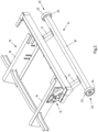
- a commercial vehicle 1 pulled by a tractor Z is shown in the form of a semi-trailer.
- the commercial vehicle shown and preferred in this respect has a box body 2 with side walls 3 , a front wall 4 , a roof 5 and rear wall doors 6 of a rear wall 7 .
- the utility vehicle 1 comprises a floor pan 8 with a loading floor 9 which extends in the longitudinal direction of the utility vehicle and on which the load of the utility vehicle 1 in the box body 2 can be parked.
- the floor assembly 8 also includes a chassis group 10, which in the illustrated and therefore preferred utility vehicle 1 includes a chassis 11 with three axles 12 arranged one behind the other. Each of the axles 12 includes at least one pair of wheels.
- the chassis group 10 also has a chassis 13 to which the chassis 10 is fixed and which carries the loading floor 9 .
- an underrun protection 14 on the chassis group 9 which is intended to prevent vehicles driving up onto the utility vehicle 1 from behind from being able to get under the chassis 13 . This is to avoid serious injury to other road users.
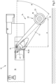
- the underrun protection 14 is fixed via two swivel joints 15 to two parallel longitudinal beams 16 of the chassis 13 . With the pivot joints 15, a web 17 of the underrun protection 14 is pivotally connected, the webs 17 at their rear Ends hold a cross member 18 which is intended to come into contact with the rear-end vehicle in the event of a rear-end collision, so as to prevent the vehicle from getting further under the chassis 13.
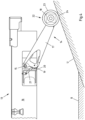
- the underrun protection 14 can hit the ground.
- the underrun protection 14 can give way in such a situation and can be adjusted from the lower driving position shown into a rearwardly pivoted and raised loading position. This is brought about solely by the force that acts on the underrun protection 14 from the ground.
- the underrun protection 14 is also arranged in the lower driving position. In this driving position, the underrun protection 14 rests with driving position stops 19 of the webs 17 on corresponding driving position stops 20 of the chassis 13 .
- the corresponding installation of the underrun protection 14 on the chassis 14 therefore provides a defined lower driving position, in which it is ensured that the underrun protection 14 can reliably prevent an approaching vehicle from underrunning the chassis 13 .
- a hold-down device 21 is provided in the form of a spring element designed as a gas pressure spring element, the restoring force of which holds the underride protection 14 against the Driving position stops 19 presses. So that the underrun protection 14 does not hit the chassis 13 excessively, damper elements can be provided on the driving position stops 19, 20 of the underrun protection 14 and/or the chassis 13. These are then preferably elastic damping elements which can be made of rubber or the like.
- the hold-down device 21 also provides a restoring force that can be overcome if the underrun protection 14 pressed against the ground, as may be the case in a loading situation.
- Underrun protection 14 is pivoted against the restoring force of hold-down device 21, so that hold-down device 21 typically presses underrun protection 14 continuously against the subsurface U and underrun protection 14 is always swiveled just as far as the loading situation requires without damaging the Underrun protection 14 or the chassis 13 to risk.
- the underrun protection 14 carries a roller 22 assigned to each of the two transverse ends, which can come into contact with the ground U and then roll along the ground U.
- the roller 22 can be a roller 22 with a running surface 23 made of an elastic material in order to dampen the impact of the underrun protection 14 on the ground U.
- the rollers therefore provide stop surfaces 24 on their running surfaces 23 for contact of the underrun protection 14 with the ground U, which is why each roller 22 also forms a lower end of the underrun protection 14 .
- the stop surfaces 24 of the rollers 22 are also spaced rearwardly from the swivel joints 15 in the longitudinal direction of the chassis 13, so that the underrun protection 14 does not tilt when it is placed on the ground U, but instead reliably swivels backwards and upwards.
- the distance A of the stop surfaces 24 of the rollers 22 from the swivel joints 15 is in the longitudinal direction of the chassis 13 in the illustrated and insofar preferred chassis group 10 in the lower driving position according to 3 about 50 cm.
- the webs 17 also extend at an angle W of approximately 45° with respect to a straight line between the stop surfaces 24 of the rollers 22 and the swivel joints 15 of the webs 17 with respect to the longitudinal extent of the chassis 13.
- the underrun protection 14 can again reliably fulfill the function of preventing the chassis 13 from being driven under.
- the underrun protection 14 can again reliably fulfill the function of preventing the chassis 13 from being driven under.
- the underrun protection 14 can again reliably fulfill the function of preventing the chassis 13 from being driven under.
- the underrun protection 14 can again reliably fulfill the function of preventing the chassis 13 from being driven under.
- the underrun protection 14 can again reliably fulfill the function of preventing the chassis 13 from being driven under.
- the underrun protection 14 there is no need for the driver to intervene, whether before or after loading. So it is not necessary to allow the underrun protection 14 to pivot out of the lower driving position before loading.
- the underrun protection 14 It is also not necessary for the underrun protection 14 to be locked in an upper loading position before loading and/or in the lower driving position after loading. A locking in the lower driving position and/or in a loading position could be provided. In many cases, however, this will not be the case for reasons of simplicity and cost.
Landscapes
- Engineering & Computer Science (AREA)
- Mechanical Engineering (AREA)
- Body Structure For Vehicles (AREA)
Abstract
Beschrieben und dargestellt ist eine Fahrgestellgruppe (10) eines Nutzfahrzeugs (1), insbesondere Lastkraftwagen, Anhänger oder Sattelauflieger, mit einem Chassis (13) und einem dem hinteren Ende des Chassis (13) zugeordneten und von dem Chassis (13) getragenen Unterfahrschutz (14) zur Vermeidung eines Unterfahrens des Chassis (13) im Falle eines Auffahrunfalls, wobei der Unterfahrschutz (14) von einer unteren Fahrstellung in Richtung des hinteren Endes des Chassis (13) und nach oben in eine Mehrzahl von Verladestellungen und zurück verstellbar ist. Damit das Nutzfahrzeug zuverlässiger verladen werden kann, ist vorgesehen, dass wenigstens ein verstellbarer Niederhalter (21) derart vorgesehen ist, so dass der Unterfahrschutz (14) gegen eine Rückstellkraft des Niederhalters (21) von der Fahrstellung in die mehreren Verladestellungen verstellbar ist.

Description
Die Erfindung betrifft eine Fahrgestellgruppe eines Nutzfahrzeugs, insbesondere Lastkraftwagen, Anhänger oder Sattelauflieger, mit einem Chassis und einem dem hinteren Ende des Chassis zugeordneten und von dem Chassis getragenen Unterfahrschutz zur Vermeidung eines Unterfahrens des Chassis im Falle eines Auffahrunfalls, wobei der Unterfahrschutz von einer unteren Fahrstellung in Richtung des hinteren Endes des Chassis und nach oben in eine Mehrzahl von Verladestellungen und zurück verstellbar ist. Ferner betrifft die Erfindung eine Bodengruppe eines Nutzfahrzeugs mit einer entsprechenden Fahrgestellgruppe und ein Nutzfahrzeug mit einer entsprechenden Bodengruppe oder mit einer entsprechenden Fahrgestellgruppe.The invention relates to a chassis group of a commercial vehicle, in particular a truck, trailer or semi-trailer, with a chassis and an underride guard assigned to the rear end of the chassis and carried by the chassis to prevent the chassis from driving under in the event of a rear-end collision, the underride guard being in a lower driving position toward the rear of the chassis and upwardly to a plurality of loading positions and back. Furthermore, the invention relates to an underbody of a commercial vehicle with a corresponding chassis group and a commercial vehicle with a corresponding underbody or with a corresponding chassis group.
Nutzfahrzeuge sind in unterschiedlichen Ausgestaltungen, etwa in Form von Lastkraftwagen, Anhängern oder Sattelaufliegern, bekannt. Dabei sind die Nutzfahrzeuge unabhängig von ihrer Ausgestaltung insbesondere für den Transport von Gütern, also der zu transportierenden Ladung, überwiegend im öffentlichen Straßenverkehr vorgesehen. Die Nutzfahrzeuge können Planenaufbauten aufweisen, die wenigstens eine Plane zum Verschließen wenigstens einer Seite und/oder eines Dachs des Planenaufbaus aufweisen. Wenn eine Plane entlang einer Seitenwand verschoben werden kann, spricht man auch von sogenannten Curtainsidern. Im Gegensatz dazu sind bei sogenannten Kofferaufbauten die Seitenwände und das Dach durch feste Wände verschlossen. Zudem ist rückwärtig ein Türrahmen in Form eines Rückwandrahmens vorgesehen, an dem zwei Türen in Form von Rückwandtüren gehalten und in dem in der geschlossenen Stellung der Türen die Türen aufgenommen sind. Gegenüber von dem Rückwandrahmen ist eine Stirnwand vorgesehen. Dabei können entsprechende Stirnwände und Rückwände in gleicher Weise bei Planenaufbauten und bei Kofferaufbauten vorgesehen sein.Commercial vehicles are known in different configurations, for example in the form of trucks, trailers or semi-trailers. Irrespective of their design, commercial vehicles are primarily intended for the transport of goods, ie the load to be transported, primarily on public roads. The commercial vehicles can have tarpaulin structures that have at least one tarpaulin for closing at least one side and/or a roof of the tarpaulin structure. If a tarpaulin can be moved along a side wall, one also speaks of so-called curtainsiders. In contrast, in so-called box bodies, the side walls and the roof are closed by solid walls. In addition, a door frame is provided at the rear in the form of a rear wall frame, on which two doors are held in the form of rear wall doors and in which the doors are accommodated when the doors are in the closed position. A front wall is provided opposite the rear wall frame. Included corresponding end walls and rear walls can be provided in the same way for tarpaulin structures and for box bodies.
Bei Kofferaufbauten können die Seitenwände, das Dach, die Stirnwand, der Boden und/oder die Türen in Form von mehrschichtigen Nutzfahrzeugpaneelen aufgebaut sein, die strukturgebende Innendecklagen, strukturgebende Außendecklagen und dazwischen eine Kernlage aus geschäumtem Kunststoff umfassen. Die entsprechenden Außendecklagen und Innendecklagen können bedarfsweise selbst jeweils mehrlagig ausgebildet sein und dienen der Aussteifung der Nutzfahrzeugpaneele, weshalb die Außendecklagen und Innendecklagen meist wenigstens eine Schicht aus einem Metall und/oder einem faserverstärkten Kunststoff aufweisen. Die einzelnen Nutzfahrzeugpaneele eines Kofferaufbaus werden typischerweise jeweils über Eck miteinander verbunden, um einen quaderförmigen Kofferaufbau zu bilden, der darin einen Laderaum zur Aufnahme der zu transportierenden Güter bereithält.In the case of box bodies, the side walls, the roof, the front wall, the floor and/or the doors can be constructed in the form of multi-layer commercial vehicle panels which comprise structuring inner cover layers, structuring outer cover layers and a core layer made of foamed plastic in between. The corresponding outer cover layers and inner cover layers can themselves be multi-layered if required and serve to stiffen the commercial vehicle panels, which is why the outer cover layers and inner cover layers usually have at least one layer made of a metal and/or a fiber-reinforced plastic. The individual commercial vehicle panels of a box body are typically connected to one another at a corner in order to form a cuboid box body that has a loading space ready for accommodating the goods to be transported.
Da die Kernlage der Nutzfahrzeugpaneele aus einem geschäumten Kunststoff eine hohe thermische Isolation bereitstellen kann, sind entsprechende Kofferaufbauten insbesondere auch für den Transport von temperaturempfindlichen Gütern, also beispielsweise für den sogenannten Kühltransport, geeignet. Dieselben Kofferaufbauten können auch für den Transport von feuchtigkeitsempfindlichen Gütern, also den sogenannten Trockentransport, verwendet werden.Since the core layer of the commercial vehicle panels made of a foamed plastic can provide a high level of thermal insulation, corresponding box bodies are also particularly suitable for the transport of temperature-sensitive goods, for example for so-called refrigerated transport. The same box bodies can also be used to transport moisture-sensitive goods, i.e. dry transport.
Die bekannten Nutzfahrzeuge weisen ein Chassis und ein an dem Chassis festgelegtes Fahrwerk mit einem oder mehreren Räderpaaren auf. Man spricht in diesem Zusammenhang auch von einachsigen, zweiachsigen oder dreiachsigen Nutzfahrzeugen, auch wenn die Räder der entsprechenden Räderpaare nicht körperlich durch eine Achse verbunden sein müssen, sondern auch über eine Einzelradaufhängung verfügen können. Ja nach Art des Nutzfahrzeugs können die Räderpaare dem vorderen oder dem hinteren Ende des Nutzfahrzeugs zugeordnet sein. Dies ist meist bei mehrachsigen Anhängern der Fall. Bei Sattelaufliegern sind die Räderpaare jedoch mit einem nicht unerheblichen Abstand zum vorderen sowie zum hinteren Ende des Nutzfahrzeugs vorgesehen. Von dem Fahrwerk wird eine Bodenstruktur getragen, die einen Ladeboden bereitstellen kann, auf den sich zu transportierende Ladung aufstellen lässt. Im Falle von sogenannten Kipperfahrzeugen, kann die Bodenstruktur eine Mulde tragen, in der Schüttgut transportiert werden kann. Die Bodenstruktur bildet zusammen mit einer Fahrgestellgruppe eine Bodengruppe des Nutzfahrzeugs aus. Dabei umfasst die Fahrgestellgruppe wenigstens das Chassis und einen Unterfahrschutz. Zudem kann die Fahrgestellgruppe noch das eigentliche Fahrwerk umfassen.The known commercial vehicles have a chassis and a running gear fixed to the chassis with one or more pairs of wheels. In this context, one also speaks of single-axle, two-axle or three-axle commercial vehicles, even if the wheels of the corresponding wheel pairs do not have to be physically connected by an axle, but can also have an independent wheel suspension. Depending on the type of utility vehicle, the wheel pairs may be associated with the front or rear end of the utility vehicle. This is mostly the case with multi-axle trailers. With semi-trailers they are Pairs of wheels, however, provided with a not inconsiderable distance to the front and to the rear end of the commercial vehicle. A floor structure is carried by the chassis and can provide a loading floor on which the load to be transported can be placed. In the case of so-called tipper vehicles, the floor structure can carry a trough in which bulk goods can be transported. Together with a chassis group, the floor structure forms a floor assembly of the commercial vehicle. The chassis group includes at least the chassis and an underrun protection. In addition, the chassis group can also include the actual chassis.
Fahrgestellgruppen von Nutzfahrzeugen weisen bis auf einige Ausnahmen einen hinteren Unterfahrschutz auf. Dieser ist typischerweise gesetzlich vorgeschrieben und soll ein Unterfahren des Chassis durch Fahrzeuge verhindern, die von hinten auf das Nutzfahrzeug auffahren. Zu diesem Zweck weist ein Unterfahrschutz meist einen Querträger auf, der von einem von hinten auf das Nutzfahrzeug auffahrenden Fahrzeug angefahren wird und so verhindert, dass das auffahrende Fahrzeug weiter unter das Chassis gelangen kann. Auf diese Weise sollen nach Möglichkeit schwerwiegende Verletzungen von Verkehrsteilnehmern vermieden werden. Dieser Schutz ist grundsätzlich umso ausgeprägter, wenn der Unterfahrschutz weiter nach unten ragt und somit tiefer angefahren werden kann.With a few exceptions, chassis groups of commercial vehicles have a rear underrun protection. This is typically required by law and is intended to prevent vehicles driving under the chassis from behind the commercial vehicle. For this purpose, an underrun protection usually has a cross member which is hit by a vehicle driving up against the commercial vehicle from behind and thus prevents the driving vehicle from getting further under the chassis. This is to avoid serious injuries to road users as far as possible. This protection is generally all the more pronounced if the underrun protection protrudes further down and can therefore be approached lower.
Der Unterfahrschutz eines Nutzfahrzeugs kann jedoch in bestimmten Situationen auf dem Untergrund aufsetzen. Dies ist insbesondere der Fall, wenn das Nutzfahrzeug eine Rampe hinauf fährt, wie dies beispielsweise beim Verladen von Nutzfahrzeugen auf Schiffe der Fall sein kann. Bei einem entsprechenden Kontakt wirken infolge des nicht unerheblichen Gewichts des Nutzfahrzeugs bedarfsweise erhebliche Kräfte auf den Unterfahrschutz ein. Infolge dieser Kräfte kann es zu Beschädigungen des Unterfahrschutzes oder sogar des Chassis des Nutzfahrzeugs kommen, was den sicheren Betrieb des Nutzfahrzeugs gefährdet und erhebliche Reparaturkosten nach sich ziehen kann.However, the underrun protection of a commercial vehicle can touch the ground in certain situations. This is particularly the case when the utility vehicle drives up a ramp, as may be the case, for example, when loading utility vehicles onto ships. In the event of such contact, considerable forces may act on the underrun protection as a result of the not inconsiderable weight of the commercial vehicle. As a result of these forces, the underrun protection or even the chassis of the commercial vehicle can be damaged, which jeopardizes the safe operation of the commercial vehicle and can entail considerable repair costs.
Daher lieget der vorliegenden Erfindung die Aufgabe zugrunde, die Fahrgestellgruppe, die Bodengruppe und das Nutzfahrzeug jeweils der eingangs genannten und zuvor näher erläuterten Art derart auszugestalten und weiterzubilden, dass das Nutzfahrzeug zuverlässiger verladen werden kann.The present invention is therefore based on the object of designing and developing the chassis group, the underbody group and the commercial vehicle of the type mentioned at the outset and previously explained in more detail in such a way that the commercial vehicle can be loaded more reliably.
Diese Aufgabe ist bei einer Fahrgestellgruppe nach dem Oberbegriff von Anspruch 1 dadurch gelöst, dass wenigstens ein verstellbarer Niederhalter derart vorgesehen ist, so dass der Unterfahrschutz gegen eine Rückstellkraft des Niederhalters von der Fahrstellung in die mehreren Verladestellungen verstellbar ist.This object is achieved with a chassis group according to the preamble of
Die Aufgabe ist ferner gemäß Anspruch 14 gelöst durch eine Bodengruppe eines Nutzfahrzeugs, insbesondere Lastkraftwagen, Anhänger oder Sattelauflieger, mit einer Fahrgestellgruppe nach einem der Ansprüche 1 bis 13 und einem sich in Längsrichtung des Chassis oberhalb des Chassis erstreckenden Ladeboden zum Aufstellen von Ladung.The object is also achieved according to
Zudem ist die genannte Aufgabe gemäß Anspruch 15 gelöst durch ein Nutzfahrzeug, insbesondere Lastkraftwagen, Anhänger oder Sattelauflieger, mit einer Bodengruppe nach Anspruch 14 oder mit einer Fahrgestellgruppe nach einem der Ansprüche 1 bis 13.In addition, the stated object is achieved according to
Durch die Verstellbarkeit des Unterfahrschutzes aus der unteren Fahrstellung in eine Mehrzahl von unterschiedlichen oberen Verladestellungen kann der Unterfahrschutz durch den beim Verladen gegebenenfalls auftretenden Kontakt mit dem Untergrund so weit nach hinten oben ausgelenkt werden, dass das Verladen nicht weiter behindert wird. Gleichzeitig wird so eine Beschädigung der Fahrgestellgruppe vermieden, die auftreten könnte, wenn der Unterfahrschutz nicht aus der unteren Fahrstellung in eine obere Verladestellung verstellt werden könnte. Der Kontakt mit dem Untergrund kann beim Verladen der Nutzfahrzeuge insbesondere beim Auffahren auf eine Rampe und/oder beim Herunterfahren von einer Rampe erfolgen, indem der Unterfahrschutz auf dem Untergrund aufsetzt. Der Unterfahrschutz kann dann nach hinten oben bezogen auf das Chassis ausweichen, um eine Beschädigung des Nutzfahrzeugs zu vermeiden. Dies kann prinzipiell unabhängig davon erfolgen, ob der Unterfahrschutz beim Vorwärts- oder Rückwärtsfahren des Nutzfahrzeugs mit einem Hindernis oder dem Untergrund in Kontakt gerät.Due to the adjustability of the underrun protection from the lower driving position into a plurality of different upper loading positions, the underrun protection can be deflected so far backwards and upwards through the contact with the ground that may occur during loading that the loading is no longer hindered. At the same time, damage to the chassis group is avoided, which could occur if the underrun protection could not be adjusted from the lower driving position to an upper loading position. Contact with the ground can occur during loading of the commercial vehicles, in particular when driving onto a ramp and/or driving down a ramp, in that the underrun protection touches down on the ground. The underrun protection can then swerve backwards and upwards in relation to the chassis to avoid damaging the utility vehicle. In principle, this can take place independently of whether the underride protection comes into contact with an obstacle or the ground when the commercial vehicle is driving forwards or backwards.
Dabei ist es besonders bevorzugt, weil besonders zweckmäßig, wenn der Unterfahrschutz aus der Fahrstellung stufenlos verstellt werden kann. Der Unterfahrschutz kann dann prinzipiell in im Wesentlichen beliebig viele Verladestellungen verstellt werden. Mit anderen Worten kann der Unterfahrschutz immer gerade soweit aus der Fahrstellung ausgelenkt werden, wie es zweckmäßig oder erforderlich ist, um dem Hindernis oder dem Untergrund auszuweichen, wenn der Unterfahrschutz mit dem Hindernis oder dem Untergrund in Kontakt gerät.It is particularly preferred because it is particularly expedient if the underrun protection can be continuously adjusted from the driving position. In principle, the underrun protection can then be adjusted in essentially any number of loading positions. In other words, the underrun protection can always be deflected from the driving position just as far as is expedient or necessary in order to avoid the obstacle or the ground when the underrun protection comes into contact with the obstacle or the ground.
Durch die Verwendung eines Niederhalters, der dem entsprechenden Schwenken des Unterfahrschutzes nach oben eine Rückstellkraft entgegensetzt, wird sichergestellt, dass der Unterfahrschutz so weit wie nötig oder nicht übermäßig ausgelenkt wird. Ansonsten könnte der Unterfahrschutz in einer oberen Stellung mit erheblicher Geschwindigkeit gegen das Chassis schlagen und dieses oder den Unterfahrschutz selbst beschädigen. Zudem sorgt die Rückstellkraft des Niederhalters dafür, dass der Unterfahrschutz nach dem Kontakt mit dem Untergrund wieder in die untere Fahrstellung zurückgelangt, um so wieder unmittelbar die eigentliche Funktion des Unterfahrschutzes auszuüben. Es kann so auch nicht zu einer Fehlbedienung durch den Fahrer kommen, etwa indem er vergisst, den Unterfahrschutz freizugeben oder den Unterfahrschutz wieder zurück nach unten zu verstellen.The use of a hold-down device, which opposes a restoring force to the corresponding upward pivoting of the underrun protection, ensures that the underrun protection is deflected as far as necessary or not excessively. Otherwise, the skid plate could hit the chassis in an up position with considerable speed and damage it or the skid plate itself. In addition, the restoring force of the hold-down device ensures that the underrun protection returns to the lower driving position after contact with the ground, so that the actual function of the underrun protection can be carried out again immediately. This also prevents the driver from operating incorrectly, for example by forgetting to release the underride protection or to adjust the underride protection back down again.
Bei einer ersten besonders bevorzugten Ausgestaltung der Fahrgestellgruppe ist der wenigstens eine Niederhalter als Federelement ausgebildet. Auf diese Weise kann sehr einfach, kostengünstig und zuverlässig die erforderliche Rückstellkraft aufgebracht werden, um den Unterfahrschutz zurück in die untere Fahrstellung zu verstellen und dort auch zuverlässig zu halten. Dies wird umso mehr erreicht, wenn das Federelement ein Gasdruckfederelement ist, welches hinsichtlich ihrer Federkennlinie sehr genau an die jeweiligen Anforderungen angepasst werden kann.In a first particularly preferred embodiment of the chassis group, the at least one hold-down device is designed as a spring element. In this way, the required restoring force can be applied very easily, inexpensively and reliably in order to adjust the underrun protection back to the lower driving position and also to keep it there reliably. This is all the more achieved when the spring element is a gas pressure spring element, which can be very precisely adapted to the respective requirements in terms of its spring characteristic.
Unabhängig davon kann der wenigstens eine Niederhalter so vorgesehen sein, dass der Unterfahrschutz über den gesamten Verstellweg von der unteren Fahrstellung in die Verladestellungen, insbesondere in die oberste mögliche Verladestellung, entgegen der Rückstellkraft des wenigstens einen Niederhalters verstellbar ist. Das führt dazu, dass der Unterfahrschutz aus jeder der möglichen Verladestellungen infolge der Rückstellkraft zuverlässig und definiert in die unterer Fahrstellung zurückgelangt. Zudem wird verhindert, dass der Unterfahrschutz undefiniert und ungedämpft nach oben ausgelenkt wird. Auf diese Weise können Beschädigungen an dem Unterfahrschutz oder dem Chassis vermieden werden.Irrespective of this, the at least one hold-down device can be provided in such a way that the underrun protection can be adjusted over the entire adjustment path from the lower driving position to the loading positions, in particular to the uppermost possible loading position, against the restoring force of the at least one hold-down device. As a result, the underride guard returns to the lower driving position reliably and in a defined manner from any of the possible loading positions as a result of the restoring force. In addition, this prevents the underrun protection from being deflected upwards in an undefined and undamped manner. In this way, damage to the underrun protection or the chassis can be avoided.
Dabei bietet es sich insbesondere an, wenn der wenigstens eine Niederhalter so vorgesehen ist, dass der Unterfahrschutz selbsttätig aus den Verladestellungen in Richtung der Rückstellkraft des wenigstens einen Niederhalters zurück in die untere Fahrstellung verstellbar ist. So wird zuverlässig erreicht, dass der Unterfahrschutz seine Funktion zu jeder Zeit ausüben kann, ohne dass es dafür zwingend eines Eingriffs des Fahrers bedarf. Dies gilt insbesondere dann, wenn die Verstellung nicht nur selbsttätig, sondern auch zwangsweise erfolgt. Zwangsweise bedeutet dabei, dass die Verstellung des Unterfahrschutzes zurück in die Fahrstellung automatisch erfolgt, wenn und in dem Maße das Chassis sich, etwa in einer Verladesituation, weiter vom Untergrund entfernt. Dabei spielt es weiter vorzugsweise keine Rolle, in welcher der Verladestellungen sich der Unterfahrschutz befindet. So kann der Unterfahrschutz vorzugsweise auch aus der obersten möglichen Verladestellung selbsttätig in Richtung der Rückstellkraft des wenigstens einen Niederhalters zurück in die untere Fahrstellung verstellbar sein.It is particularly useful if the at least one hold-down device is provided in such a way that the underrun protection can be automatically adjusted from the loading positions in the direction of the restoring force of the at least one hold-down device back into the lower driving position. This reliably ensures that the underrun protection can carry out its function at any time without the driver having to intervene. This applies in particular when the adjustment is not only automatic but also forced. Mandatory means that the underrun protection is automatically adjusted back to the driving position if and to the extent that the chassis moves further away from the ground, for example in a loading situation. In this context, it preferably plays no role in which of the loading positions the underrun protection is located. The underride guard can preferably also be automatically adjustable from the uppermost possible loading position back into the lower driving position in the direction of the restoring force of the at least one hold-down device.
Zudem kann vorgesehen sein, dass der Unterfahrschutz in den Verladestellungen, insbesondere in der obersten möglichen Verladestellung, nicht arretierbar vorgesehen ist. Es ist dann also nicht nur so, dass der Unterfahrschutz in der Verladestellung nicht arretiert werden muss, was mit einem zusätzlichen Aufwand für den Fahrer einhergehen würde. Es wäre tatsächlich so, dass keine Arretierung in einer Verladestellung erfolgen kann. So wäre sichergestellt, dass der Unterfahrschutz immer wieder zurück in die untere Fahrstellung gelangt und dass der Unterfahrschutz so seine eigentliche Funktion ausüben kann. Es kann dann nämlich schlicht nicht vergessen werden, die Arretierung wieder zu lösen, oder ein beabsichtigtes Lösen der Arretierung fehlschlagen.In addition, it can be provided that the underrun protection is not provided in a lockable manner in the loading positions, in particular in the uppermost possible loading position. So it's not just that the underrun protection in the Loading position does not have to be locked, which would entail additional effort for the driver. It would actually be the case that no locking can take place in a loading position. This would ensure that the underrun protection always returns to the lower driving position and that the underrun protection can perform its actual function. It is then simply not possible to forget to release the lock again, or an intended release of the lock can fail.
Besonders einfach und zuverlässig ist es, wenn das Chassis wenigstens ein Schwenkgelenk zum Schwenken des Unterfahrschutzes von der unteren Fahrstellung in die Verladestellungen, insbesondere die oberste mögliche Verladestellung, und zurück in die untere Fahrstellung aufweist. Fehlfunktionen können dadurch verringert werden. Außerdem können entsprechende Schwenkgelenke recht hohe Kräfte aufnehmen und weiterleiten, so dass auch bei widrigeren Verladesituationen eine nachhaltige Beschädigung des Unterfahrschutzes und seiner Aufhängung am Chassis vermieden werden kann.It is particularly simple and reliable if the chassis has at least one swivel joint for swiveling the underrun protection from the lower driving position into the loading positions, in particular the uppermost possible loading position, and back into the lower driving position. This can reduce malfunctions. In addition, corresponding swivel joints can absorb and transmit very high forces, so that permanent damage to the underrun protection and its suspension on the chassis can be avoided even in adverse loading situations.
Das Chassis kann alternativ oder zusätzlich wenigstens einen Fahrstellungsanschlag zum Anschlagen an wenigstens einen Fahrstellungsanschlag des Unterfahrschutzes in der unteren Fahrstellung aufweisen. Auf diese Weise lässt sich die untere Fahrstellung des Unterfahrschutzes zuverlässig definieren, so dass der Unterfahrschutz seine eigentliche Funktion stets ausüben kann. Wenn darüber hinaus der wenigstens eine Fahrstellungsanschlag des Chassis und/oder der wenigstens eine Fahrstellungsanschlag des Unterfahrschutzes wenigstens ein elastisches Dämpferelement zum Dämpfen des Anschlagens des wenigstens einen Fahrstellungsanschlags des Unterfahrschutzes an den wenigstens einen Fahrstellungsanschlag des Chassis aufweist, kann die gesamte Konstruktion geschont werden. Es kommt dann nicht zu übermäßigen Schlägen des Unterfahrschutzes an das Chassis, wenn der Unterfahrschutz zurück in die untere Fahrstellung verstellt wird. Die Dämpfung kann somit vermeiden, dass es zu Beschädigungen an dem Unterfahrschutz oder dem Chassis kommt.Alternatively or additionally, the chassis can have at least one driving position stop for striking at least one driving position stop of the underride protection in the lower driving position. In this way, the lower driving position of the underrun protection can be reliably defined, so that the underrun protection can always perform its actual function. If, in addition, the at least one driving position stop of the chassis and/or the at least one driving position stop of the underride protection has at least one elastic damping element for damping the impact of the at least one driving position stop of the underride protection on the at least one driving position stop of the chassis, the entire construction can be protected. This prevents the underrun protection from hitting the chassis excessively when the underrun protection is adjusted back to the lower driving position. The damping can thus prevent damage to the underrun protection or the chassis.
Alternativ oder zusätzlich kann das Chassis wenigstens einen Verladeanschlag zum Anschlagen an wenigstens einen Verladeanschlag des Unterfahrschutzes in der obersten möglichen Verladestellung aufweisen. Dadurch wird sichergestellt, dass der Unterfahrschutz nicht über die vorgesehene oberste Verladestellung hinaus verstellt werden kann. Dies könnte ansonsten etwa passieren, wenn der Unterfahrschutz, etwa in einer Verladesituation, sehr heftig auf dem Untergrund aufschlägt. Dann könnte der Unterfahrschutz so stark nach oben ausgelenkt werden, dass der Unterfahrschutz unkontrolliert gegen das Chassis schlägt. Dies könnte dann zu einer Beschädigung des Chassis oder des Unterfahrschutzes führen. Dabei bietet es sich an, wenn der wenigstens eine Verladeanschlag des Chassis und/oder der wenigstens eine Verladeanschlag des Unterfahrschutzes wenigstens ein elastisches Dämpferelement zum Dämpfen des Anschlagens des wenigstens einen Verladeanschlags des Unterfahrschutzes an den wenigstens einen Verladeanschlag des Chassis aufweist. Auf diese Weise können die Kräfte über das Dämpferelement abgeleitet werden, um den Unterfahrschutz und das Chassis vor übermäßiger Krafteinleitung zu schützen.Alternatively or additionally, the chassis can have at least one loading stop for striking at least one loading stop of the underrun protection in the uppermost possible loading position. This ensures that the underrun protection cannot be adjusted beyond the intended top loading position. This could otherwise happen, for example, if the underrun protection hits the ground very hard, for example in a loading situation. Then the underrun protection could be deflected upwards so much that the underrun protection hits the chassis in an uncontrolled manner. This could then lead to damage to the chassis or the underrun protection. It is advisable if the at least one loading stop of the chassis and/or the at least one loading stop of the underrun protection has at least one elastic damping element for damping the impact of the at least one loading stop of the underrun protection against the at least one loading stop of the chassis. In this way, the forces can be dissipated via the damping element in order to protect the underrun protection and the chassis from excessive force application.
Wird dem unteren Ende des Unterfahrschutzes wenigstens eine Rolle und/oder eine Kufe zugeordnet, kann vermieden werden, dass sich der Unterfahrschutz am Untergrund verhakt, wenn der Unterfahrschutz in Kontakt mit dem Untergrund kommt. Dies ist umso mehr der Fall, wenn ein Paar Rollen, und/oder ein Paar Kufen zur Anlage an einen Untergrund bei einer Verladung vorgesehen werden. Die wenigstens eine Rolle und/oder die wenigstens eine Kufe kann dabei so dem unteren Ende, bedarfsweise dem unteren Rand, des Unterfahrschutzes zugeordnet sein, dass der Unterfahrschutz zuerst mit der Rolle und/oder der Kufe in Kontakt mit einem ebenen Untergrund oder Boden gelangt. Dies kann beispielsweise erreicht werden, wenn die wenigstens eine Rolle und/oder die wenigstens eine Kufe ein unteres Ende des Unterfahrschutzes bildet.If at least one roller and/or one skid is assigned to the lower end of the underrun protection, it can be avoided that the underrun protection gets caught on the ground when the underrun protection comes into contact with the ground. This is all the more the case when a pair of rollers and/or a pair of skids are provided to rest against a substrate during loading. The at least one roller and/or the at least one runner can be assigned to the lower end, if necessary the lower edge, of the underrun protection in such a way that the underrun protection first comes into contact with the roller and/or the runner with a level surface or floor. This can be achieved, for example, if the at least one roller and/or the at least one runner forms a lower end of the underrun protection.
Die wenigstens eine Rolle und/oder die wenigstens eine Kufe stellen also vornehmlich einen Anschlag gegenüber dem Untergrund bereit. Dieser Anschlag kann dabei in Längsrichtung des Chassis um wenigstens 20 cm, vorzugsweise wenigstens 40 cm, insbesondere wenigstens 60 cm, hinter dem wenigstens einen Schwenkgelenk angeordnet sein. Über diesen Abstand wird im Falle eines Kontakts des Unterfahrschutzes mit dem Untergrund ein Moment gegenüber dem Schwenkgelenk bewirkt. Infolge dieses Moments wird zuverlässig erreicht, dass der Unterfahrschutz tatsächlich auch um das Schwenkgelenk nach oben schwenkt und sich nicht etwa zwischen dem Untergrund und dem Chassis verkeilt, was zu erheblichen Beschädigungen des Unterfahrschutzes und/oder des Chassis führen kann. Je größer der Abstand zwischen dem Anschlag und dem wenigstens einen Schwenkgelenk ist, desto größer ist das um das Schwenkgelenk wirkende Moment und umso zuverlässiger wird ein unproblematisches Auslenken des Unterfahrschutzes nach oben in eine Verladestellung bewirkt. Der wenigstens eine Anschlag ist dabei in Längsrichtung hinter dem Schwenkgelenk angeordnet, womit gemeint ist, dass der Anschlag weiter in Richtung des hinteren Endes des Chassis vorgesehen ist als das wenigstens eine Schwenkgelenk, das mithin gegenüber dem wenigstens einen Anschlag weiter in Richtung des vorderen Endes des Chassis vorgesehen ist.The at least one roller and/or the at least one runner therefore primarily provide a stop against the ground. This attack can In the longitudinal direction of the chassis at least 20 cm, preferably at least 40 cm, in particular at least 60 cm, behind the at least one swivel joint. In the event of contact between the underrun protection and the ground, this distance causes a moment in relation to the swivel joint. As a result of this moment, it is reliably achieved that the underrun protection actually pivots upwards about the swivel joint and does not get wedged between the ground and the chassis, which can lead to considerable damage to the underrun protection and/or the chassis. The greater the distance between the stop and the at least one swivel joint, the greater the moment acting around the swivel joint and the more reliably an unproblematic upward deflection of the underride protection into a loading position is effected. The at least one stop is arranged in the longitudinal direction behind the pivot joint, which means that the stop is provided further in the direction of the rear end of the chassis than the at least one pivot joint, which is therefore further in the direction of the front end of the at least one stop Chassis is provided.
Der Unterfahrschutz umfasst der Einfachheit halber wenigstens einen sich quer zum Chassis erstreckenden Querträger und wenigstens zwei den wenigstens einen Querträger mit dem Chassis verbindende Stege. Der Querträger muss dabei nicht zwingend in einem rechten Winkel zur Längserstreckung des Chassis verlaufen. Auch muss der Querträger nicht unbedingt geradlinig ausgebildet sein. Es sind also auch Abweichungen von der genannten Form und der genannten Erstreckung möglich, auch wenn wenigstens im Wesentlichen geradlinig verlaufende und/oder sich rechtwinklig zur Längserstreckung des Chassis orientierte Querträger bevorzugt sein können.For the sake of simplicity, the underrun protection comprises at least one cross member extending transversely to the chassis and at least two webs connecting the at least one cross member to the chassis. The cross member does not necessarily have to run at a right angle to the longitudinal extension of the chassis. Also, the cross member does not necessarily have to be straight. Deviations from the named shape and the named extent are also possible, even if cross members that run at least essentially in a straight line and/or are oriented at right angles to the longitudinal extent of the chassis can be preferred.
Um ein zuverlässiges Auslenken des Unterfahrschutzes von der unteren Fahrstellung in eine obere Verladestellung sicherzustellen, kann es sich anbieten, wenn sich die Stege in der unteren Fahrstellung in einem Winkel zur Längserstreckung des Chassis von weniger als 75°, vorzugsweise weniger als 65°, insbesondere von weniger als 55°, in Richtung des Querträgers erstrecken. Ein entsprechender Winkel kann dabei auch dazu beitragen, dass der Unterfahrschutz sowohl beim Vorwärtsfahren als auch beim Rückwärtsfahren des Nutzfahrzeugs beschädigungsfrei aus der Fahrstellung in eine geeignete Verladestellung verstellt werden kann. Dabei können die Stege der Einfachheit halber wenigstens im Wesentlichen geradlinig ausgebildet sein. Zwingend ist dies aber nicht. Bei nicht wenigstens im Wesentlichen geradlinig ausgebildeten Stegen kann anstatt deren tatsächlicher Erstreckung eine effektive Erstreckung herangezogen werden, um den zuvor angesprochenen Winkel zu bestimmen. Die effektive Erstreckung wird dann durch das wenigstens eine Schwenkgelenk mit der wenigstens einen zugehörigen Rolle und/oder der wenigstens einen zugehörigen Kufe, insbesondere dem Anschlag der entsprechenden Rolle und/oder Kufe, gebildet.In order to ensure reliable deflection of the underrun protection from the lower driving position to an upper loading position, it can be advisable if the webs in the lower driving position are at an angle to the longitudinal extent of the chassis of less than 75°, preferably less than 65°, in particular of less than 55°, extend in the direction of the cross member. A corresponding angle can also contribute to the underrun protection being able to be adjusted from the driving position to a suitable loading position without damage both when driving forwards and when reversing the commercial vehicle. In this case, for the sake of simplicity, the webs can be formed at least substantially in a straight line. But this is not mandatory. In the case of webs that are not at least essentially rectilinear, an effective extent can be used instead of their actual extent in order to determine the previously mentioned angle. The effective extent is then formed by the at least one swivel joint with the at least one associated roller and/or the at least one associated runner, in particular the stop of the corresponding roller and/or runner.
Hinsichtlich des Chassis bietet es sich für Aussteifung und Ableitung von großen Kräften an, wenn das Chassis zwei Längsträger und wenigstens zwei die Längsträger miteinander verbindende Querträger aufweist. In einer Verladesituation kann der Unterfahrschutz dann recht heftig auf dem Untergrund aufschlagen, ohne dass dies zu Beschädigungen am Chassis führt. Zudem kann zweckmäßigerweise an dem Chassis wenigstens ein Fahrwerk zum Verfahren des Nutzfahrzeugs festgelegt sein. Das Fahrwerk kann dabei eine oder auch mehrere Achsen aufweisen. Im Falle von Sattelaufliegern bieten sich insbesondere drei Achsen mit jeweils wenigstens einem Räderpaar an.With regard to the chassis, it is advisable for stiffening and dissipating large forces if the chassis has two longitudinal members and at least two cross members connecting the longitudinal members to one another. In a loading situation, the underrun protection can then hit the ground quite violently without causing damage to the chassis. In addition, at least one running gear for moving the commercial vehicle can expediently be fixed to the chassis. The chassis can have one or more axes. In the case of semi-trailers, three axles, each with at least one pair of wheels, are particularly suitable.
Nachfolgend wird die Erfindung anhand einer lediglich ein Ausführungsbeispiel darstellenden Zeichnung näher erläutert. In der Zeichnung zeigt
- Fig. 1
- ein erfindungsgemäßes Nutzfahrzeug mit einer erfindungsgemäßen Bodengruppe umfassend eine erfindungsgemäße Fahrgestellgruppe in einer perspektivischen Ansicht,
- Fig. 2
- ein Detail der Fahrgestellgruppe des Nutzfahrzeugs aus
Fig. 1 mit einem Unterfahrschutz in einer unteren Fahrstellung in einer perspektivischen Ansicht, - Fig. 3
- die Fahrgestellgruppe aus
Fig. 2 mit dem Unterfahrschutz in einer unteren Fahrstellung in einer Seitenansicht und - Fig. 4
- die Fahrgestellgruppe aus
Fig. 2 mit dem Unterfahrschutz in einer oberen Verladestellung in der Seitenansicht gemäßFig. 3 .
- 1
- a commercial vehicle according to the invention with an underbody according to the invention comprising a chassis group according to the invention in a perspective view,
- 2
- a detail of the chassis group of the
commercial vehicle 1 with an underrun protection in a lower driving position in a perspective view, - 3
- the
chassis group 2 with the underrun protection in a lower driving position in a side view and - 4
- the
chassis group 2 with the underrun protection in an upper loading position in the side view according to3 .
In der
In der
In der
In der
Der Unterfahrschutz 14 trägt den beiden Querenden zugeordnet jeweils eine Rolle 22, die mit dem Untergrund U in Kontakt kommen und dann entlang des Untergrunds U abrollen kann. Bei der Rolle 22 kann es sich um eine Rolle 22 mit einer Lauffläche 23 aus einem elastischen Material handeln, um den Aufschlag des Unterfahrschutzes 14 auf den Untergrund U zu dämpfen. Die Rollen stellen mithin an ihren Laufflächen 23 Anschlagflächen 24 für den Kontakt des Unterfahrschutzes 14 mit dem Untergrund U bereit, weshalb jede Rolle 22 zudem ein unteres Ende des Unterfahrschutzes 14 bildet. Die Anschlagflächen 24 der Rollen 22 sind ferner in Längsrichtung des Chassis 13 nach hinten von den Schwenkgelenken 15 beabstandet, so dass der Unterfahrschutz 14 beim Aufsetzen auf den Untergrund U nicht verkantet, sondern zuverlässig nach hinten oben schwenkt. Der Abstand A der Anschlagflächen 24 der Rollen 22 von den Schwenkgelenken 15 beträgt in Längsrichtung des Chassis 13 bei der dargestellten und insoweit bevorzugten Fahrgestellgruppe 10 in der unteren Fahrstellung gemäß
Wenn sich der Untergrund U beim weiteren Verladen wieder vom Chassis 13 entfernt, so wird der Unterfahrschutz 14 zunehmend wieder zurück in Richtung der unteren Fahrstellung geschwenkt. Dies wird durch eine entsprechende Rückstellkraft der beiden, den Stegen 17 des Unterfahrschutzes 14 zugeordneten Niederhaltern 21 bewirkt. In der unteren Fahrstellung angekommen kann der Unterfahrschutz 14 die Funktion, ein Unterfahren des Chassis 13 zu vermeiden, wieder zuverlässig erfüllen. Dabei bedarf es bei dem dargestellten und insoweit bevorzugten Nutzfahrzeug 1 keines Eingriffs des Fahrers, sei es vor oder nach dem Verladen. Es muss also nicht etwa vor dem Verladen ein Verschwenken des Unterfahrschutzes 14 aus der unteren Fahrstellung freigegeben werden. Es muss auch nicht der Unterfahrschutz 14 vor dem Verladen in einer oberen Verladestellung und/oder nach dem Verladen in der unteren Fahrstellung arretiert werden. Eine Arretierung in der unteren Fahrstellung und/oder in einer Verladestellung könnte zwar vorgesehen sein. In vielen Fällen wird dies aber der Einfachheit halber und aus Kostengründen nicht der Fall sein.If the subsurface U moves away from the
- 11
- Nutzfahrzeugcommercial vehicle
- 22
- Kofferaufbaubox body
- 33
- SeitenwandSide wall
- 44
- Stirnwandbulkhead
- 55
- DachRoof
- 66
- Rückwandtürrear door
- 77
- Rückwandback panel
- 88th
- Bodengruppeunderbody
- 99
- Ladebodencargo floor
- 1010
- Fahrgestellgruppechassis group
- 1111
- Fahrwerklanding gear
- 1212
- Achseaxis
- 1313
- Chassischassis
- 1414
- Unterfahrschutzunderrun protection
- 1515
- Schwenkgelenkswivel joint
- 1616
- Längsträgerside members
- 1717
- Stegweb
- 1818
- Querträgercross member
- 19,2019.20
- Fahrstellungsanschlagdriving position stop
- 2121
- Niederhalterhold-down
- 2222
- Rollerole
- 2323
- Laufflächetread
- 2424
- Anschlagflächestop surface
- ZZ
- Zugmaschinetractor
Claims (15)
dadurch gekennzeichnet, dass
wenigstens ein verstellbarer Niederhalter (21) derart vorgesehen ist, so dass der Unterfahrschutz (14) gegen eine Rückstellkraft des Niederhalters (21) von der Fahrstellung in die mehreren Verladestellungen verstellbar ist.Chassis group (10) of a commercial vehicle (1), in particular a truck, trailer or semi-trailer, with a chassis (13) and an underrun protection (14) assigned to the rear end of the chassis (13) and carried by the chassis (13) to prevent underrunning of the chassis (13) in the event of a rear-end collision, the underrun protection (14) being adjustable from a lower driving position in the direction of the rear end of the chassis (13) and upwards into a plurality of loading positions and back,
characterized in that
at least one adjustable hold-down device (21) is provided in such a way that the underrun protection (14) can be adjusted from the driving position into the several loading positions against a restoring force of the hold-down device (21).
dadurch gekennzeichnet, dass
der wenigstens eine Niederhalter (21) als Federelement, insbesondere Gasdruckfederelement, ausgebildet ist.Chassis group according to claim 1,
characterized in that
the at least one hold-down device (21) is designed as a spring element, in particular a gas pressure spring element.
dadurch gekennzeichnet, dass
der wenigstens eine Niederhalter (21) so vorgesehen ist, dass der Unterfahrschutz (14) über den gesamten Verstellweg von der unteren Fahrstellung in die Verladestellungen, insbesondere in die oberste, mögliche Verladestellung, entgegen der Rückstellkraft des wenigstens einen Niederhalters (21) verstellbar ist.Chassis group according to claim 1 or 2,
characterized in that
the at least one hold-down device (21) is provided in such a way that the underrun protection (14) can be adjusted over the entire adjustment path from the lower driving position to the loading positions, in particular into the uppermost possible loading position, against the restoring force of the at least one hold-down device (21).
dadurch gekennzeichnet, dass
der wenigstens eine Niederhalter (21) so vorgesehen ist, dass der Unterfahrschutz (14) selbsttätig, insbesondere zwangsweise, aus den Verladestellungen, insbesondere aus der obersten möglichen Verladestellung, in Richtung der Rückstellkraft des wenigstens einen Niederhalters (21) zurück in die untere Fahrstellung verstellbar ist.Chassis group according to one of claims 1 to 3,
characterized in that
the at least one hold-down device (21) is provided in such a way that the underrun protection (14) can be automatically, in particular forcibly, adjusted from the loading positions, in particular from the uppermost possible loading position, back into the lower driving position in the direction of the restoring force of the at least one hold-down device (21). is.
dadurch gekennzeichnet, dass
der Unterfahrschutz (14) in den Verladestellungen, insbesondere in der obersten möglichen Verladestellung, nicht arretierbar vorgesehen ist.Chassis group according to one of claims 1 to 4,
characterized in that
the underrun protection (14) is not provided in a lockable manner in the loading positions, in particular in the uppermost possible loading position.
dadurch gekennzeichnet, dass
das Chassis (13) wenigstens ein Schwenkgelenk (15) zum Schwenken des Unterfahrschutzes (14) von der unteren Fahrstellung in die Verladestellungen, insbesondere die oberste mögliche Verladestellung, und zurück in die untere Fahrstellung aufweist.Chassis group according to one of claims 1 to 5,
characterized in that
the chassis (13) has at least one swivel joint (15) for swiveling the underrun protection (14) from the lower driving position into the loading positions, in particular the uppermost possible loading position, and back into the lower driving position.
dadurch gekennzeichnet, dass
das Chassis (13) wenigstens einen Fahrstellungsanschlag (19) zum Anschlagen an wenigstens einen Fahrstellungsanschlag (20) des Unterfahrschutzes (14) in der unteren Fahrstellung aufweist und dass, vorzugsweise, der wenigstens eine Fahrstellungsanschlag (19) des Chassis (13) und/oder der wenigstens eine Fahrstellungsanschlag (20) des Unterfahrschutzes (14) wenigstens ein elastisches Dämpferelement zum Dämpfen des Anschlagens des wenigstens einen Fahrstellungsanschlags (20) des Unterfahrschutzes (14) an den wenigstens einen Fahrstellungsanschlag (19) des Chassis (13) aufweist.Chassis group according to one of claims 1 to 6,
characterized in that
the chassis (13) has at least one driving position stop (19) for striking at least one driving position stop (20) of the underrun protection (14) in the lower driving position and that, preferably, the at least one driving position stop (19) of the chassis (13) and/or the at least one driving position stop (20) of the underride protection (14) has at least one elastic damping element for damping the impact of the at least one driving position stop (20) of the underride protection (14) on the at least one driving position stop (19) of the chassis (13).
dadurch gekennzeichnet, dass
das Chassis (13) wenigstens einen Verladeanschlag zum Anschlagen an wenigstens einen Verladeanschlag des Unterfahrschutzes (14) in der obersten möglichen Verladestellung aufweist und dass, vorzugsweise, der wenigstens eine Verladeanschlag des Chassis (13) und/oder der wenigstens eine Verladeanschlag des Unterfahrschutzes (14) wenigstens ein elastisches Dämpferelement zum Dämpfen des Anschlagens des wenigstens einen Verladeanschlags des Unterfahrschutzes (14) an den wenigstens einen Verladeanschlag des Chassis (13) aufweist.Chassis group according to one of claims 1 to 7,
characterized in that
the chassis (13) has at least one loading stop for attaching to at least one loading stop of the underrun protection (14) in the uppermost possible loading position and that, preferably, the at least one loading stop of the chassis (13) and/or the at least one loading stop of the underrun protection (14 ) has at least one elastic damping element for damping the striking of the at least one loading stop of the underrun protection (14) against the at least one loading stop of the chassis (13).
dadurch gekennzeichnet, dass
dem unteren Ende des Unterfahrschutzes (14) zugeordnet wenigstens eine Rolle (22), insbesondere ein Paar Rollen (22), und/oder wenigstens eine Kufe, insbesondere ein Paar Kufen, zur Anlage an einen Untergrund (U) bei einer Verladung vorgesehen ist.Chassis group according to one of claims 1 to 8,
characterized in that
at least one roller (22), in particular a pair of rollers (22), and/or at least one skid, in particular a pair of skids, is assigned to the lower end of the underrun protection (14) and is intended to rest against a substrate (U) during loading.
dadurch gekennzeichnet, dass
das untere Ende des Unterfahrschutzes (14), vorzugsweise die wenigstens eine Rolle (22), insbesondere das Paar Rollen (22), und/oder die wenigstens eine Kufe, insbesondere das Paar Kufen einen unteren Anschlag (24) gegenüber dem Untergrund (U) bereitstellt und dass der Anschlag (24) in Längsrichtung des Chassis (13) um wenigstens 20 cm, vorzugsweise wenigstens 40 cm, insbesondere wenigstens 60 cm, hinter dem wenigstens einen Schwenkgelenk (15) angeordnet ist.Chassis group according to one of claims 6 to 9,
characterized in that
the lower end of the underrun protection (14), preferably the at least one roller (22), in particular the pair of rollers (22), and/or the at least one runner, in particular the pair of runners, a lower stop (24) relative to the ground (U) and that the stop (24) is arranged in the longitudinal direction of the chassis (13) by at least 20 cm, preferably at least 40 cm, in particular at least 60 cm, behind the at least one swivel joint (15).
dadurch gekennzeichnet, dass
der Unterfahrschutz (14) wenigstens einen quer zum Chassis (13) verlaufenden Querträger (18) und wenigstens zwei den Querträger (18) mit dem Chassis (13) verbindende Stege (17) vorgesehen sind.Chassis group according to one of claims 1 to 10,
characterized in that
the underrun protection (14) has at least one transverse to the chassis (13). Cross member (18) and at least two webs (17) connecting the cross member (18) to the chassis (13) are provided.
dadurch gekennzeichnet, dass
sich die Stege (17) in der unteren Fahrstellung in einem Winkel (W) zur Längserstreckung des Chassis (13) von weniger als 75°, vorzugsweise weniger als 65°, insbesondere von weniger als 55°, in Richtung des Querträgers (18) erstrecken.Chassis group according to claim 10,
characterized in that
the webs (17) extend in the lower driving position at an angle (W) to the longitudinal extent of the chassis (13) of less than 75°, preferably less than 65°, in particular less than 55°, in the direction of the cross member (18). .
dadurch gekennzeichnet, dass
das Chassis (13) zwei Längsträger (16) und wenigstens zwei die Längsträger (16) miteinander verbindende Querträger aufweist und dass, vorzugsweise, an dem Chassis (13) wenigstens ein Fahrwerk (11) zum Verfahren des Nutzfahrzeugs (1) festgelegt ist.Chassis group according to one of claims 1 to 12,
characterized in that
the chassis (13) has two longitudinal members (16) and at least two cross members connecting the longitudinal members (16) to one another and that, preferably, at least one running gear (11) for moving the commercial vehicle (1) is fixed to the chassis (13).
Priority Applications (1)
| Application Number | Priority Date | Filing Date | Title |
|---|---|---|---|
| EP22150676.9A EP4209394A1 (en) | 2022-01-10 | 2022-01-10 | Driving unit of a commercial vehicle with underride protection, floor assembly and commercial vehicle |
Applications Claiming Priority (1)
| Application Number | Priority Date | Filing Date | Title |
|---|---|---|---|
| EP22150676.9A EP4209394A1 (en) | 2022-01-10 | 2022-01-10 | Driving unit of a commercial vehicle with underride protection, floor assembly and commercial vehicle |
Publications (1)
| Publication Number | Publication Date |
|---|---|
| EP4209394A1 true EP4209394A1 (en) | 2023-07-12 |
Family
ID=79287960
Family Applications (1)
| Application Number | Title | Priority Date | Filing Date |
|---|---|---|---|
| EP22150676.9A Withdrawn EP4209394A1 (en) | 2022-01-10 | 2022-01-10 | Driving unit of a commercial vehicle with underride protection, floor assembly and commercial vehicle |
Country Status (1)
| Country | Link |
|---|---|
| EP (1) | EP4209394A1 (en) |
Citations (4)
| Publication number | Priority date | Publication date | Assignee | Title |
|---|---|---|---|---|
| DE2603283A1 (en) * | 1975-02-07 | 1976-08-19 | Saviem | REAR SAFETY SHOCK ABSORBER FOR VEHICLES |
| DE2914847A1 (en) * | 1979-04-11 | 1980-10-23 | Quinton Hazell Holdings Ltd | Crash bar for rear of lorry - has sprung damper and swing up facility to prevent damage on ramps |
| DE8717907U1 (en) * | 1987-07-07 | 1991-05-02 | Daimler-Benz Aktiengesellschaft, 7000 Stuttgart, De | |
| CN202200931U (en) * | 2011-07-29 | 2012-04-25 | 徐昭 | Apparatus preventing car from plunging into truck bottom due to rear-end collision |
-
2022
- 2022-01-10 EP EP22150676.9A patent/EP4209394A1/en not_active Withdrawn
Patent Citations (4)
| Publication number | Priority date | Publication date | Assignee | Title |
|---|---|---|---|---|
| DE2603283A1 (en) * | 1975-02-07 | 1976-08-19 | Saviem | REAR SAFETY SHOCK ABSORBER FOR VEHICLES |
| DE2914847A1 (en) * | 1979-04-11 | 1980-10-23 | Quinton Hazell Holdings Ltd | Crash bar for rear of lorry - has sprung damper and swing up facility to prevent damage on ramps |
| DE8717907U1 (en) * | 1987-07-07 | 1991-05-02 | Daimler-Benz Aktiengesellschaft, 7000 Stuttgart, De | |
| CN202200931U (en) * | 2011-07-29 | 2012-04-25 | 徐昭 | Apparatus preventing car from plunging into truck bottom due to rear-end collision |
Similar Documents
| Publication | Publication Date | Title |
|---|---|---|
| DE60215537T2 (en) | UNTERFAHRSCHUTZ DEVICE | |
| DE3200792A1 (en) | "VEHICLE TRAILER" | |
| WO2018041396A1 (en) | Body for a passenger car | |
| DE1921477A1 (en) | Device for connecting a loading frame to a tractor unit | |
| EP1162111B1 (en) | Loading tailgate system with sliding unit | |
| EP4209394A1 (en) | Driving unit of a commercial vehicle with underride protection, floor assembly and commercial vehicle | |
| EP3581468B1 (en) | Chassis structure, chassis structure system and chassis of a commercial vehicle | |
| EP3260358B1 (en) | Commercial vehicle chassis | |
| EP1645462B1 (en) | Motor vehicle | |
| EP1462346B1 (en) | Stanchion system for a railway vehicle. | |
| EP3623218B1 (en) | Carriage for a transport vehicle for transporting rolling containers | |
| EP2219904B1 (en) | Underride prevention device for a heavy goods vehicle | |
| EP2431222B1 (en) | Commercial vehicle for transporting containers | |
| EP4296148A1 (en) | Box body with back panel and commercial vehicles with a box body | |
| EP4276262A1 (en) | Structure with head frame profile | |
| DE102016115786B4 (en) | Load securing device for commercial vehicles | |
| DE102022120671B3 (en) | Commercial vehicle loading space with weather protection device, commercial vehicle train and method for operating a weather protection device | |
| EP3875354B1 (en) | Transport trailer | |
| DE19919953A1 (en) | Front-end loading system for semi-trailer on lorry | |
| EP4122724A1 (en) | Rear wall deflector | |
| EP1180450B1 (en) | Loading tailgate with connecting flange | |
| EP3437926A1 (en) | Luggage structure for a commercial vehicle | |
| DE102009057477A1 (en) | Safety cabin for the operator of a portal stacker | |
| DE4437925C1 (en) | Drive arrangement for vehicle roll-over protection bar | |
| EP4124547A1 (en) | Commercial vehicle with side collision device |
Legal Events
| Date | Code | Title | Description |
|---|---|---|---|
| STAA | Information on the status of an ep patent application or granted ep patent |
Free format text: STATUS: EXAMINATION IS IN PROGRESS |
|
| PUAI | Public reference made under article 153(3) epc to a published international application that has entered the european phase |
Free format text: ORIGINAL CODE: 0009012 |
|
| 17P | Request for examination filed |
Effective date: 20221208 |
|
| AK | Designated contracting states |
Kind code of ref document: A1 Designated state(s): AL AT BE BG CH CY CZ DE DK EE ES FI FR GB GR HR HU IE IS IT LI LT LU LV MC MK MT NL NO PL PT RO RS SE SI SK SM TR |
|
| STAA | Information on the status of an ep patent application or granted ep patent |
Free format text: STATUS: THE APPLICATION IS DEEMED TO BE WITHDRAWN |
|
| 18D | Application deemed to be withdrawn |
Effective date: 20230729 |