EP4209388A1 - Seat back frame assemblies and seat assemblies including pultrusion reinforcements - Google Patents
Seat back frame assemblies and seat assemblies including pultrusion reinforcements Download PDFInfo
- Publication number
- EP4209388A1 EP4209388A1 EP23150580.1A EP23150580A EP4209388A1 EP 4209388 A1 EP4209388 A1 EP 4209388A1 EP 23150580 A EP23150580 A EP 23150580A EP 4209388 A1 EP4209388 A1 EP 4209388A1
- Authority
- EP
- European Patent Office
- Prior art keywords
- seat back
- back frame
- reinforcement
- pultrusion
- slots
- Prior art date
- Legal status (The legal status is an assumption and is not a legal conclusion. Google has not performed a legal analysis and makes no representation as to the accuracy of the status listed.)
- Pending
Links
Images




Classifications
-
- A—HUMAN NECESSITIES
- A47—FURNITURE; DOMESTIC ARTICLES OR APPLIANCES; COFFEE MILLS; SPICE MILLS; SUCTION CLEANERS IN GENERAL
- A47C—CHAIRS; SOFAS; BEDS
- A47C7/00—Parts, details, or accessories of chairs or stools
- A47C7/36—Supports for the head or the back
- A47C7/40—Supports for the head or the back for the back
-
- B—PERFORMING OPERATIONS; TRANSPORTING
- B60—VEHICLES IN GENERAL
- B60N—SEATS SPECIALLY ADAPTED FOR VEHICLES; VEHICLE PASSENGER ACCOMMODATION NOT OTHERWISE PROVIDED FOR
- B60N2/00—Seats specially adapted for vehicles; Arrangement or mounting of seats in vehicles
- B60N2/68—Seat frames
- B60N2/682—Joining means
-
- B—PERFORMING OPERATIONS; TRANSPORTING
- B60—VEHICLES IN GENERAL
- B60N—SEATS SPECIALLY ADAPTED FOR VEHICLES; VEHICLE PASSENGER ACCOMMODATION NOT OTHERWISE PROVIDED FOR
- B60N2/00—Seats specially adapted for vehicles; Arrangement or mounting of seats in vehicles
- B60N2/68—Seat frames
-
- B—PERFORMING OPERATIONS; TRANSPORTING
- B60—VEHICLES IN GENERAL
- B60N—SEATS SPECIALLY ADAPTED FOR VEHICLES; VEHICLE PASSENGER ACCOMMODATION NOT OTHERWISE PROVIDED FOR
- B60N2/00—Seats specially adapted for vehicles; Arrangement or mounting of seats in vehicles
- B60N2/02—Seats specially adapted for vehicles; Arrangement or mounting of seats in vehicles the seat or part thereof being movable, e.g. adjustable
- B60N2/22—Seats specially adapted for vehicles; Arrangement or mounting of seats in vehicles the seat or part thereof being movable, e.g. adjustable the back-rest being adjustable
- B60N2/225—Seats specially adapted for vehicles; Arrangement or mounting of seats in vehicles the seat or part thereof being movable, e.g. adjustable the back-rest being adjustable by cycloidal or planetary mechanisms
- B60N2/2252—Seats specially adapted for vehicles; Arrangement or mounting of seats in vehicles the seat or part thereof being movable, e.g. adjustable the back-rest being adjustable by cycloidal or planetary mechanisms in which the central axis of the gearing lies inside the periphery of an orbital gear, e.g. one gear without sun gear
-
- B—PERFORMING OPERATIONS; TRANSPORTING
- B60—VEHICLES IN GENERAL
- B60N—SEATS SPECIALLY ADAPTED FOR VEHICLES; VEHICLE PASSENGER ACCOMMODATION NOT OTHERWISE PROVIDED FOR
- B60N2/00—Seats specially adapted for vehicles; Arrangement or mounting of seats in vehicles
- B60N2/24—Seats specially adapted for vehicles; Arrangement or mounting of seats in vehicles for particular purposes or particular vehicles
- B60N2/42—Seats specially adapted for vehicles; Arrangement or mounting of seats in vehicles for particular purposes or particular vehicles the seat constructed to protect the occupant from the effect of abnormal g-forces, e.g. crash or safety seats
- B60N2/4249—Seats specially adapted for vehicles; Arrangement or mounting of seats in vehicles for particular purposes or particular vehicles the seat constructed to protect the occupant from the effect of abnormal g-forces, e.g. crash or safety seats fixed structures, i.e. where neither the seat nor a part thereof are displaced during a crash
-
- B—PERFORMING OPERATIONS; TRANSPORTING
- B60—VEHICLES IN GENERAL
- B60N—SEATS SPECIALLY ADAPTED FOR VEHICLES; VEHICLE PASSENGER ACCOMMODATION NOT OTHERWISE PROVIDED FOR
- B60N2/00—Seats specially adapted for vehicles; Arrangement or mounting of seats in vehicles
- B60N2/64—Back-rests or cushions
-
- B—PERFORMING OPERATIONS; TRANSPORTING
- B60—VEHICLES IN GENERAL
- B60N—SEATS SPECIALLY ADAPTED FOR VEHICLES; VEHICLE PASSENGER ACCOMMODATION NOT OTHERWISE PROVIDED FOR
- B60N2/00—Seats specially adapted for vehicles; Arrangement or mounting of seats in vehicles
- B60N2/68—Seat frames
- B60N2/686—Panel like structures
-
- B—PERFORMING OPERATIONS; TRANSPORTING
- B60—VEHICLES IN GENERAL
- B60N—SEATS SPECIALLY ADAPTED FOR VEHICLES; VEHICLE PASSENGER ACCOMMODATION NOT OTHERWISE PROVIDED FOR
- B60N2/00—Seats specially adapted for vehicles; Arrangement or mounting of seats in vehicles
- B60N2/02—Seats specially adapted for vehicles; Arrangement or mounting of seats in vehicles the seat or part thereof being movable, e.g. adjustable
- B60N2/0224—Non-manual adjustments, e.g. with electrical operation
- B60N2/02246—Electric motors therefor
- B60N2/02258—Electric motors therefor characterised by the mounting of the electric motor for adjusting the seat
Definitions
- the present specification generally relates to seat back frame assemblies for a vehicle and, more particularly, seat back frame assemblies having seat back frames and a pultrusion reinforcement.
- Vehicles may include seat assemblies with a stadium style seat that is moveable between a use position and a tip-up position.
- Previously known seat assemblies may include metal or resin frames.
- a seat back frame of the seat assembly may include a reinforced member to improve the strength of the seat back frame.
- the resin frame of the seat assembly may be formed using an overmold process.
- overmold processes often exert a large amount of pressure on the reinforcement member, thereby damaging the reinforcement member or misaligning the reinforcement member within the overmold portion.
- it may be difficult to determine whether the reinforcement member is damaged or misaligned, as the overmold portion covers the reinforcement member during the overmold process.
- a seat back assembly in a first aspect, includes a pultrusion reinforcement and a seat back frame.
- the seat back frame is formed of a resin material.
- the seat back frame is only partially overmolded into the pultrusion reinforcement such that the pultrusion reinforcement is configured to be visually inspect through a plurality of openings formed in the seat back frame.
- the pultrusion reinforcement is formed of a continuous glass fiber reinforced resin material.
- the plurality of openings include a plurality of apertures and a plurality of slots.
- the pultrusion reinforcement has a generally hat shape formed by a base wall, a pair of side walls that extend from side edges of the base wall, and a pair of flanges that extend from side edges of the pair of side walls.
- the plurality of apertures are formed in the seat back frame such that a portion of the base wall of the pultrusion reinforcement is configured to be visually inspected through the plurality of apertures.
- the plurality of apertures are formed in the seat back frame such that a portion of at least one of the pair of side walls is configured to be visually inspected through the plurality of apertures.
- the seat back frame includes a first surface and an opposite second surface and the pultrusion reinforcement is positioned between the first surface and the second surface of the seat back frame.
- the plurality of apertures and the plurality of slots are formed in both the first surface and the second surface.
- the second surface of the seat back frame includes a plurality of reinforcement ribs that extend along a plurality of link portions formed in the second surface of the seat back frame, the plurality of link portions define the plurality of apertures formed in the second surface of the seat back frame.
- the pultrusion reinforcement has a generally double hat shape formed by an upper flange, an upper base wall, a center wall, a first upper side wall extending between the upper flange and the upper base wall, a second upper side wall extend between the upper base wall and the center wall, a lower base wall, a lower flange, a first lower side wall that extends between the center wall and the lower base wall, and a second lower side wall that extends between the lower base wall and the lower flange.
- the plurality of openings includes a plurality of upper apertures, a plurality of lower apertures, a plurality of upper slots, a plurality of lower slots, and a plurality of intermediate slots.
- the plurality of upper apertures are formed in the seat back frame such that a portion of the upper base wall of the pultrusion reinforcement is configured to be visually inspected through the plurality of upper apertures.
- the plurality of lower aperture are formed in the seat back frame such that a portion of the lower base wall of the pultrusion reinforcement is configured to be visually inspected through the plurality of lower apertures.
- the plurality of upper slots are formed in the seat back frame such that at least a portion of the first upper side wall of the pultrusion reinforcement is configured to be visually inspected through the plurality of upper slots.
- the plurality of lower slots are formed in the seat back frame such that at least a portion of the first lower side wall of the pultrusion reinforcement is configured to be visually inspected through the plurality of lower slots.
- the plurality of intermediate slots are formed in the seat back frame such that at least a portion of the center wall of the pultrusion reinforcement is configured to be visually inspected through the plurality of intermediate slots.
- the seat back frame includes a plurality of upper reinforcement ribs and a plurality of lower reinforcement ribs, the plurality of upper reinforcement ribs are configured to be positioned between the first upper side wall and the second upper side wall of the pultrusion reinforcement, and the plurality of lower reinforcement ribs are configured to be positioned between the first lower side wall and the second lower side wall of the pultrusion reinforcement.
- a seat assembly in an eleventh aspect, includes a seat cushion frame, a pultrusion reinforcement, and a seat back frame.
- the seat back frame is formed of a resin material.
- the seat back frame is only partially overmolded into the pultrusion reinforcement such that the pultrusion reinforcement is configured to be visually inspect through a plurality of openings formed in the seat back frame.
- the pultrusion reinforcement is formed a continuous glass fiber reinforced resin material.
- the plurality of openings includes a plurality of apertures and a plurality of slots.
- the pultrusion reinforcement has a generally hat shape formed by a base wall, a pair of side walls that extend from side edges of the base wall, and a pair of flanges that extend from side edges of the pair of side walls.
- the plurality of apertures are formed in the seat back frame such that a portion of the base wall of the pultrusion reinforcement is configured to be visually inspected through the plurality of apertures.
- the plurality of apertures are formed in the seat back frame such that a portion of at least one of the pair of side walls is configured to be visually inspected through the plurality of apertures.
- the seat back frame includes a first surface and an opposite second surface and the pultrusion reinforcement is positioned between the first surface and the second surface of the seat back frame.
- the plurality of apertures and the plurality of slots are formed in both the first surface and the second surface.
- the second surface of the seat back frame includes a plurality of reinforcement ribs that extend along a plurality of link portions formed in the second surface of the seat back frame, the plurality of link portions to define the plurality of apertures formed in the second surface of the seat back frame.
- the pultrusion reinforcement has a generally double hat shape formed by an upper flange, an upper base wall, a center wall, a first upper side wall extending between the upper flange and the upper base wall, a second upper side wall extend between the upper base wall and the center wall, a lower base wall, a lower flange, a first lower side wall that extends between the center wall and the lower base wall, and a second lower side wall that extends between the lower base wall and the lower flange.
- the plurality of openings includes a plurality of upper apertures, a plurality of lower apertures, a plurality of upper slots, a plurality of lower slots, and a plurality of intermediate slots.
- the plurality of upper apertures are formed in the seat back frame such that a portion of the upper base wall of the pultrusion reinforcement is configured to be visually inspected through the plurality of upper apertures.
- the plurality of lower aperture are formed in the seat back frame such that a portion of the lower base wall of the pultrusion reinforcement is configured to be visually inspected through the plurality of lower apertures.
- the plurality of upper slots are formed in the seat back frame such that at least a portion of the first upper side wall of the pultrusion reinforcement is configured to be visually inspected through the plurality of upper slots.
- the plurality of lower slots are formed in the seat back frame such that at least a portion of the first lower side wall of the pultrusion reinforcement is configured to be visually inspected through the plurality of lower slots.
- the plurality of intermediate slots are formed in the seat back frame such that at least a portion of the center wall of the pultrusion reinforcement is configured to be visually inspected through the plurality of intermediate slots.
- the seat back frame includes a plurality of upper reinforcement ribs and a plurality of lower reinforcement ribs, the plurality of upper reinforcement ribs are configured to be positioned between the first upper side wall and the second upper side wall of the pultrusion reinforcement, and the plurality of lower reinforcement ribs are configured to be positioned between the first lower side wall and the second lower side wall of the pultrusion reinforcement.
- a seat back assembly includes a pultrusion reinforcement and a seat back frame.
- the seat back frame is formed of a resin material.
- the seat back frame is only partially overmolded onto the pultrusion reinforcement.
- the pultrusion reinforcement is configured to be visually inspected through a plurality of openings formed in the seat back frame. By only partially overmolding the seat back frame onto the pultrusion reinforcement, an amount of pressure applied to the pultrusion reinforcement during the overmold process is reduced. Furthermore, by configuring the pultrusion reinforcement to be visually inspected through the plurality of openings formed in the seat back frame, allows an operator to verify that the pultrusion reinforcement is properly positioned and undamaged upon completion of the overmold process.
- a seat assembly includes a seat back frame, a pultrusion reinforcement, and a seat cushion frame pivotally coupled to the seat back frame.
- the seat back frame is formed of a resin material.
- the seat back frame is only partially overmolded onto the pultrusion reinforcement.
- the pultrusion reinforcement is configured to be visually inspected through a plurality of openings formed in the seat back frame.
- vehicle longitudinal direction refers to the forward-rearward direction of the vehicle (i.e. , in the +/- vehicle X-direction as depicted).
- vehicle lateral direction refers to the cross-vehicle direction of the vehicle (i.e., in the +/vehicle Z-direction as depicted), and is transverse to the vehicle longitudinal direction.
- vehicle vertical direction refers to the upward-downward direction of the vehicle ( i.e. , in the +/- vehicle Y-direction as depicted).
- the terms “upward,” “downward,” “rearward,” and “forward” are used to describe the relative positioning of various components of the vehicle relative to one another. Because the vehicle structures may be generally symmetrical about the vehicle centerline, the terms “upward,” “downward,” “rearward,” and “forward” may be switched when evaluating components positioned along opposite sides of the vehicle. Further, while certain components of the vehicle are described as extending in one of the identified directions or oriented toward one of the identified directions, it should be understood that these components extend or are oriented in at least these recited directions.
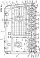
- a seat assembly 10 is generally depicted.
- the seat assembly 10 is provided within a vehicle 1, which may be a car in some embodiments.
- the vehicle 1 may be a truck, a sport utility vehicle, a van, a boat, a plane, or other vehicle types.
- the vehicle 1 includes a passenger compartment in which the seat assembly 10 positioned therein for seating occupants within the vehicle 1. While one seat assembly 10 is illustrated in FIG. 1 , it should be understood that the vehicle 1 may include any number of seat assemblies 10 in other embodiments.
- the seat assembly 10 is configured as a rear seat of the vehicle 1.
- the rear seat of the vehicle 1 may be a rear 60/40 seat that includes the seat assembly 10 and a second seat assembly (not shown).
- the seat assembly 10 may be configured as the "60" seat to support an occupant on an outer portion and in an inner portion of the seat assembly 10 in the vehicle lateral direction (i.e., in the +/- Z-direction of the coordinate axes shown in the figures).
- the seat assembly 10 may be a "50/50" seat, a captain type seat, a bucket type seat, or other various seat assemblies.
- the seat assembly 10 includes a seat back assembly 11 and a seat cushion frame 14.
- the seat back assembly 11 includes a seat back frame 12 and a pultrusion reinforcement 70.
- the pultrusion reinforcement 70 is only partially overmolded within the seat back frame 12 such that the pultrusion reinforcement 70 is configured to be visually inspected through the seat back frame 12.
- the seat back frame 12 and the seat cushion frame 14 may be coupled to each other via a pair of brackets 15.
- the brackets 15 may couple the seat back frame 12 and the seat cushion frame 14 using a fastener.
- the seat cushion frame 14 may be pivotally coupled to the seat cushion frame 14 via the brackets 15 for movement about a pivot axis P1.
- the seat cushion frame 14 may be pivotal between a seated position and a tip-up position. In the seated position, the seat cushion frame 14 is positioned to support an occupant above a floor of the vehicle 1. In the tip-up position, the seat cushion frame 14 is pivoted about the pivot axis P1 in the direction of arrow F1 towards the seat back frame 12. In the tip-up position, the seat cushion frame 14 faces the seat back frame 12.
- the seat assembly 10 may include one or more attachment points (not shown) for securely fastening the seat assembly 10 to a floor of the vehicle 1.
- the seat assembly 10 may be slidably attached to the floor of the vehicle 1 by a pair of slide rails such that the seat assembly 10 is slidable in the vehicle longitudinal direction (i.e., in the ⁇ vehicle X-direction as depicted).
- the seat cushion frame 14 may include a base wall 16, pair of side walls 18, a front wall 20, and a rear wall 22.
- the pair of side walls 18 may extend in the vehicle longitudinal direction (i.e., in the +/- X-direction) when in the seated position, as shown in FIG. 1
- the front wall 20 and the rear wall 22 may extend in the vehicle lateral direction (i.e., in the +/- Z-direction).
- the pair of side walls 18, the front wall 20, and the rear wall 22 are formed to define a perimeter of the seat cushion frame 14.
- the seat cushion frame 14 may also include a notch 23, which provides access for seatbelt buckles or other seat accessories to the occupants supported by the seat cushion frame 14.
- the seat cushion frame 14 is formed of a resin material.
- the seat cushion frame 14 may be formed of at least one resin or a combination of resins such as nylon, polyester, polyurethane, vinyl, vinyl ester, and/or epoxy.
- the seat cushion frame 14 may be formed of a fiber-reinforced resin material, for example, a glass-filled nylon resin material.
- the base wall 16, the pair of side walls 18, the front wall 20, and the rear wall 22 of the seat cushion frame 14 are integrally formed as a one-piece monolithic structure.
- the seat cushion frame 14 may be integrally molded from a fiber-reinforced resin material as a single one-piece monolithic structure.
- the seat back frame 12 includes base wall 24, an upper cross member 26, a lower cross member 28 spaced apart from the upper cross member 26, and a pair of side members 30.
- the upper cross member 26 and the lower cross member 28 may extend in the vehicle lateral direction (i.e., in the +/- Z-direction).
- the pair of side members 30 extend between ends of the upper cross member 26 and the lower cross member 28.
- the seat back frame 12 may include an intermediate cross member 32.
- the intermediate cross member 32 may extend from the upper cross member 26 towards the lower cross member 28 in the vehicle vertical direction ( i.e. , in the +/- Y-direction).
- the intermediate cross member 32 may provide for reinforcement of the seat back frame 12 in an area between where the occupants may be supported in situations in which the seat assembly 10 is a "60" seat.
- the base wall 24 of seat back frame 12 includes a front surface (hereinafter referred to as first surface) 34 and an opposite rear surface (hereinafter referred to as second surface) 36.
- the seat back frame 12 includes a reinforcement portion 105 that includes a pair of side walls 107A and an intermediate wall 107B.
- the side walls 107A and the intermediate wall 107C form a portion of the first surface 34 that at least partially covers the pultrusion reinforcement 70.
- the seat back frame 12 is formed of a resin material.
- the seat back frame 12 may be formed of at least one resin or a combination of resins such as nylon, polyester, polyurethane, vinyl, vinylester, and/or epoxy.
- the seat back frame 12 may be formed of a fiber-reinforced resin material, for example, a glass-filled nylon resin material.
- the base wall 24, the upper cross member 26, the lower cross member 28, and the intermediate cross member 32 of the seat back frame 12 are integrally formed as a one-piece monolithic structure.
- the seat back frame 12 may be integrally molded from a fiber-reinforced resin material as a single one-piece monolithic structure.
- the seat back frame 12 may include latches 38 that are integrally formed within base wall 24.
- the latches 38 may be provided as anchors to secure child safety seats.
- the seat back frame 12 may include notches 42, which provide access for seatbelt assemblies or other seat accessories to the occupants supported by the seat back frame 12.
- the upper cross member 26 may be formed having a generally U-shape that defines a recess 48 on the second surface 36 of the seat back frame 12.
- the recess 48 may be defined by a pair of surfaces 44.
- a plurality of extension ribs 46 may extend within the recess 48 such as between the pair of surfaces 44.
- the plurality of extension ribs 46 in a first direction and a second direction generally normal to the first direction such that plurality of extension ribs 46 couple to each other.
- the plurality of extension ribs 46 may be provided to reinforce the recess 48 of the upper cross member 26.
- the pair of side members 30 may be formed having a generally U-shape that defines a recess 50 in the second surface 36 of the seat back frame 12.
- the recess 50 may be defined by a pair of surfaces 52.
- a plurality of extension ribs 54 may extend within the recess 50 between the pair of surfaces 52.
- the plurality of extension ribs 54 may be provided to reinforce the recess 50 of the pair of side members 30.
- the intermediate cross member 32 may be formed having a generally U-shape that defines a recess 56 on the second surface 36 of the seat back frame 12.
- the recess 56 may be defined by a pair of surfaces 58.
- a plurality of extension ribs 60 may extend within the recess 56 between the pair of surfaces 58.
- the plurality of extension ribs 60 may be provided to reinforce the recess 56 of the intermediate cross member 32.
- a reinforcement recess 62 may be formed in the seat back frame 12 at a position in which the pultrusion reinforcement 70 is located.
- the reinforcement recess 62 may be defined by a pair of side walls 64A and an intermediate wall 64B that extends between the pair of side walls 64A.
- a plurality of reinforcement ribs 66 may extend within the reinforcement recess 62.
- the plurality of reinforcement ribs 66 may extend from the intermediate wall 64B and between the pair of side walls 64A.
- the seat back frame 12 includes the pultrusion reinforcement 70.
- the pultrusion reinforcement 70 is an elongated reinforcement member that may extend within the seat back frame 12 in the vehicle lateral direction (i.e., in the +/- vehicle Z-direction).
- the pultrusion reinforcement 70 is positioned between the lower cross member 28 and the upper cross member 26.
- the pultrusion reinforcement 70 may be positioned at other locations of the seat back frame 12 and may extend in other vehicle directions (e.g., the pultrusion reinforcement 70 may be integrally provided within the upper cross member 26 and/or the lower cross member 28).
- the pultrusion reinforcement 70 is configured to further reinforce a rigidity of the seat back frame 12.
- the pultrusion reinforcement 70 is only partially overmolded into the seat back frame 12 during the molding process of the seat back frame 12. Specifically, the pultrusion reinforcement 70 is overmolded by the seat back frame 12 such that the pultrusion reinforcement 70 is positioned between the first surface 34 and the second surface 36 of the seat back frame 12. In some embodiments, the seat back frame 12 and the pultrusion reinforcement 70 are integrally molded as a one-piece monolithic structure.
- the pultrusion reinforcement 70 is formed having a generally hat shape.
- the pultrusion reinforcement 70 includes a base wall 90, a pair of side walls 92, a pair of flanges 94, and a pair of distal edges 96.
- the pultrusion reinforcement 70 may have other various geometric shapes, for example, a planar shape, regular shape, an irregular shape, or a complex shape.
- the base wall 90 includes a first surface 90A, an opposite second surface 90B, and a pair of side edges 90C that extend between the first surface 90A and the second surface 90B.
- the first surface 90A of the base wall 90 is positioned so as to face an inner side of the first surface 34 of the seat back frame 12.
- the second surface 90B of the base wall 90 is positioned within the seat back frame 12 so as to face an inner side of the second surface 36 of the seat back frame 12.
- the pair of side walls 92 include a first surface 92A, an opposite second surface 92B, and a pair of side edges 92C. Each of the pair of side walls 92 extend generally normal from the side edges 90C of the base wall 90. Each of the first surfaces 92A of the pair of side walls 92 is positioned within the seat back frame 12 so as to face an inner side of the first surface 34 of the seat back frame 12. Each of the second surfaces 92B of the pair of side walls 92 is positioned within the seat back frame 12 so as to face an inner side of the second surface 36 of the seat back frame 12.
- the pair of flanges 94 include a first surface 94A and an opposite second surface 94B. Each of the pair of flanges 94 extend generally normal from side edges 92C of the pair of side walls 92. Each of the pair of flanges 94 extend between the side edges 92C of the pair of side walls 92 and the pair of distal edges 96. Each of the first surfaces 94A of the pair of flanges 94 is positioned within the seat back frame 12 so as to face an inner side of the first surface 34 of the seat back frame 12. Each of the second surfaces 92B of the pair of flanges 94 is positioned within the seat back frame 12 so as to face an inner side of the second surface 36 of the seat back frame 12.
- the pultrusion reinforcement 70 may also include a pair of bores 98.
- Each of the pair of bores 98 is positioned adjacent an end portion of the pultrusion reinforcement 70 in the longitudinal direction of the pultrusion reinforcement 70.
- the pair of bores 98 are formed in the base wall 90.
- Each of the pair of bores 98 extend between the first surface 90A and the opposite second surface 90B of the base wall 90.
- the pair of bores 98 aid in the retention of the pultrusion reinforcement 70 in a predetermined position as the seat back frame 12 is overmolded onto the pultrusion reinforcement 70.
- the pultrusion reinforcement 70 may be formed of a continuous fiber reinforced resin material.
- the pultrusion reinforcement 70 may include a resin composite material and one or more fibers extending in one direction.
- the one or more fibers may be glass fibers such as continuous glass fibers.
- the one or more fibers may be glass fibers and nylon fibers (e.g., 95% of the one or more fibers are glass fibers, and 5% of the one or more fibers are nylon fibers).
- the one or more fibers may be configured to reinforce the resin composite material (e.g., resins such as epoxy, polyester, etc.) of the pultrusion reinforcement 70.
- the glass fibers may increase a tensile strength, flex modulus, impact resistance, and dimensional stability of the pultrusion reinforcement 70.
- the pultrusion reinforcement 70 is formed of a continuous glass fiber reinforced resin material.
- the pultrusion reinforcement 70 is formed using a continuous molding pultrusion process in which the reinforcing fibers, such as long strand glass-fibers, are saturated with a liquid resin material, such as a liquid polymer resin, then pulled through a heated forming die to create the generally hat shape of the pultrusion reinforcement 70.
- a liquid resin material such as a liquid polymer resin
- pigments and catalysts that enhance the curing of pultrusion reinforcement 70 may be added while the one or more continuous glass fibers are saturated with the liquid resin material. It should be understood that the pultrusion reinforcement 70 may be formed using any suitable pultrusion process or other suitable manufacturing process in other embodiments.
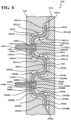
- the first surface 34 of the seat back frame 12 is formed with a plurality of openings 100 positioned such that visual access to the pultrusion reinforcement 70 is permitted through the first surface 34 of the seat back frame 12.
- the plurality of openings 100 includes a plurality of shaped apertures 102 formed in the intermediate wall 107B and a plurality of slots 104 formed in the pair of side walls 107A and the intermediate wall 107B.
- the plurality of shaped apertures 102 and the plurality of slots 104 are separated by a plurality of link portions 106 and a plurality of parallel extension portions 108.
- the plurality of extension portions 108 extend from a top side and a bottom side of the plurality of link portions 106.
- the plurality of link portions 106 have a generally X-shape when viewed from a front of the seat back frame 12.
- the plurality of link portions 106 includes interior sides 106A that define the plurality of shaped apertures 102 between with a generally regular shape.
- the plurality of link portions 106 includes exterior sides 106B that together with the plurality of extension portions 108 define the plurality of slots 104.
- the plurality of shaped apertures 102 are formed having a generally rhombus shape. It is appreciated that the shape of the plurality of shaped apertures 102 is not limited to generally rhombus shapes and may include other regular and non-regular geometric shapes, illustratively including triangles, circles, semicircles, and rectangles.
- the plurality of shaped apertures 102 are formed in the first surface 34 of the seat back frame 12, by the interior sides 106A of the plurality of link portions 106, so as to be positioned over at least a portion of the base wall 90 of the pultrusion reinforcement 70. As such, at least a portion of the first surface 90A of the base wall 90 is configured to be visually inspected through the plurality of shaped apertures 102 formed in the seat back frame 12.
- the plurality of slots 104 are formed having a generally triangular shaped end defined by the exterior sides 106B of the plurality of link portions 106, and a remainder of the plurality of slots 104 are formed having a generally rectangular shape as each of the plurality of slots 104 are formed between adjacent extension portions 108.
- the plurality of slots 104 are formed in the first surface 34 of the seat back frame 12, by the exterior sides 106B of the plurality of link portions 106 and adjacent extension portions 108, so as to be positioned over at least a portion of the base wall 90, the pair of side walls 92, and the pair of flanges 94 of the pultrusion reinforcement 70.
- the plurality of link portions 106 of the seat back frame 12 include junctions 101.
- the junctions 101 are intersections of the plurality of link portions 106 of the first surface 34.
- the plurality of extension portions 108 are formed in the first surface 34 of the seat back frame 12 so as to extend upwardly and downwardly from the top and bottom, respectively, of the plurality of link portions 106.
- the plurality of extension portions 108 are formed so as to extend over at least a portion of each of the first surface 90A of the base wall 90, a portion of each of the first surfaces 92A of the pair of side walls 92, and a portion of the first surfaces 94A of the pair of flanges 94.
- the second surface 36 of the seat back frame 12 is formed with a plurality of openings 110 positioned such that visual access to the pultrusion reinforcement 70 is permitted through the second surface 36 of the seat back frame 12.
- the plurality of openings 110 formed in the second surface 36 of the seat back frame 12 includes a plurality of shaped apertures 112 formed in the intermediate wall 64B and a plurality of slots 114 formed in the side walls 64A and the intermediate wall 64B.
- the plurality of shaped apertures 112 and the plurality of slots 114 are separated by a plurality of link portions 116 and a plurality of extension portions 118.
- the plurality of extension portions 118 extend from a top side and a bottom side of the plurality of link portions 116.
- the plurality of link portions 116 have a generally X-shape when viewed from a rear of the seat back frame 12.
- the plurality of link portions 116 have interior sides 116A that define the plurality of shaped apertures 112 between with a generally regular shape.
- the plurality of link portions 116 have exterior sides 116B that together with the plurality of extension portions 118 define the plurality of slots 114.
- the plurality of shaped apertures 112 are formed having a generally rhombus shape. It is appreciated that the shape of the plurality of shaped apertures 112 is not limited to generally rhombus shapes and may include other regular and non-regular geometric shapes, illustratively including triangles, circles, semicircles, and rectangles.
- the plurality of shaped apertures 112 are formed in the second surface 36 of the seat back frame 12, by the interior sides 116A of the plurality of link portions 116, to as to be positioned over at least a portion of the base wall 90 of the pultrusion reinforcement 70. As such, at least a portion of the second surface 90B of the base wall 90 is configured to be visually inspected through the plurality of shaped apertures 112 formed in the seat back frame 12.
- the plurality of slots 114 are formed having a generally triangular shaped end defined by the exterior sides 116B of the plurality of link portions 116 and a remainder of the plurality of slots 114 are formed having a generally rectangular shape as each of the plurality of slots 114 are formed between adjacent extension portions 118.
- the plurality of slots 114 are formed in the second surface 36 of the seat back frame 12, by the exterior sides 116B of the plurality of link portions 116 and adjacent extension portions 118, so as to be positioned over at least a portion of the base wall 90, the pair of side walls 92, and the pair of flanges 94 of the pultrusion reinforcement 70.
- the plurality of link portions 116 of the seat back frame 12 include junctions 111.
- the junctions 111 are intersections of the plurality of link portions 116 of the second surface 36.
- the plurality of extension portions 118 are formed in the second surface 36 of the seat back frame 12 so as to extend upwardly and downwardly from the top and bottom, respectively, of the plurality of link portions 116.
- the plurality of extension portions 118 are formed so as to extend over at least a portion of the second surface 90B of the base wall 90, a portion of each of the second surfaces 92B of the pair of side walls 92, and a portion of each of the second surfaces 94B of the pair of flanges 94.
- the generally hat shape of the pultrusion reinforcement 70 defines the reinforcement recess 62.
- the plurality of reinforcement ribs 66 are positioned on and extend outwardly from the plurality of link portions 116.
- the plurality of reinforcement ribs 66 couple the plurality of link portions 116 to the side walls 64A of the reinforcement recess 62.
- the plurality of reinforcement ribs 66 have a shape that corresponds to the shape of the plurality of link portions 116.
- the plurality of reinforcement ribs 66 have a generally X-shape to accommodate the generally X-shape of the plurality of link portions 116, when viewed from a rear of the seat back frame 12.
- the plurality of reinforcement ribs 66 are configured to further reinforce a rigidity of the seat back frame 12.
- the plurality of link portions 106 may have a first thickness (T 1 ), and the plurality of ribs 66 may have a second thickness (T 2 ).
- the second thickness (T 2 ) is greater than or equal to the first thickness (T 1 ). It should be understood that the second thickness (T 2 ) may be less than the first thickness (T 1 ) in other embodiments.
- the first thickness (T 1 ) is taken at the junction 101 and the second thickness (T 2 ) is taken at the junction 111 which extends through the reinforcement ribs 66.
- the first thickness (Ti) is a thickness of the intermediate wall 107B and the second thickness (T 2 ) is a thickness of the intermediate wall 64B and the ribs 66.
- the embodiments illustrate the plurality of link portions 106, the plurality of link portions 116, and the plurality of ribs 66 having a generally X-shape
- the plurality of link portions 106, the plurality of link portions 116, and the plurality of ribs 66 may have other geometrical configurations that enable the pultrusion reinforcement 70 to be visually inspected through the seat back frame 12 in other embodiments.
- at least one of the plurality of link portions 106 and the plurality of link portions 116 having a generally circular or elliptical shape.
- the bracket 15 may be positioned adjacent (i.e., proximate or near) the pultrusion reinforcement 70 and may be configured to pivotally couple the side member 30 to the seat cushion frame 14 using a fastening member 99 (e.g., a rotatable fastening nut, a pivot bolt, a hinge, or other fastening element of the like).
- a fastening member 99 e.g., a rotatable fastening nut, a pivot bolt, a hinge, or other fastening element of the like.
- the pultrusion reinforcement 70 may be formed during a pultrusion process.
- the pultrusion process may include spooling one or more continuous glass fibers using a tension roller.
- the one or more continuous glass fibers may then be placed in a resin bath (e.g., a polyester, polyurethane, vinylester, epoxy, etc.), and the resin may permeate the one or more continuous glass fibers.
- a resin bath e.g., a polyester, polyurethane, vinylester, epoxy, etc.
- pigments and catalysts that enhance the curing of the pultrusion reinforcement 70 may be added while the one or more continuous glass fibers are within the resin bath. Subsequently, the mixture of the one or more continuous glass fibers and the resin may be provided to a heat source, such as a steel-forming die, in order to polymerize the resin. The polymerized resin and one or more continuous glass fibers are removed from the heat source as a solid fiberglass reinforced polymer. It should be understood that the pultrusion reinforcement 70 may be formed using any suitable pultrusion process or other suitable manufacturing process in other embodiments.
- the pultrusion reinforcement 70 may be formed in a generally hat shape and including include the base wall 90, the pair of side walls 92, the pair of flanges 94, and the pair of distal edges 96.
- the pultrusion reinforcement 70 is only partially overmolded within the seat back frame 12 such that the pultrusion reinforcement 70 is configured to be visually inspected through the seat back frame 12 through the plurality of openings 100 and plurality of openings 110.
- the pultrusion reinforcement 70 is placed into an overmold chamber 120.
- the pultrusion reinforcement 70 may be positioned between a first molding substrate 130 and a second molding substrate 140 of the overmold chamber 120.
- At least one of the first molding substrate 130 and the second molding substrate 140 may each include at least two pin bores 181 for receiving locating pins 180 (e.g., a two-way locating pin and a four-way locating pin), and the pair of bores 98 of the pultrusion reinforcement 70 may be aligned with the locating pins 180.
- the locating pins 180 are aligned with and extend into the bores 98 of the pultrusion reinforcement 70 such that ends of the locating pins 180 contact a portion of the second molding substrate 140 upon closing of the overmold chamber 120.
- the second molding substrate 140 may include bores 182 that are configured to receive the locating pins 180.
- the bores 182 are bottomed cavities and in some other embodiments, the bores 182 are throughbores that extend through the second molding substrate 140.
- the engagement between the pair of bores 98 and the locating pins 180 retain the pultrusion reinforcement 70 in a predetermined position with respect to the overmold chamber 120 as the seat back frame 12 is overmolded onto the pultrusion reinforcement 70.
- the overmold chamber 120 is sealed and isolated from an environment external to the overmold chamber 120.
- an injection molding material may be provided within the overmold chamber 120.
- the injection molding material may be a nylon, polyester, polyurethane, vinyl, vinyl ester, and/or epoxy, or other any other suitable injection molding material.
- an additive material e.g., plasticizers, fibers, flame-retardants, colorants, etc.
- the overmold chamber 120 defines a cavity between the first molding substrate 130 and the second molding substrate 140, in which the pultrusion reinforcement 70 is positioned during the overmold process.
- Each of the first molding substrate 130 and the second molding substrate 140 may have a geometry such that when the injection molding material in the overmold chamber 120 is cured, the pultrusion reinforcement 70 is positioned between the first surface 34 and the second surface 36 of the seat back frame 12.
- the first molding substrate 130 may have a geometry such that when the injection molding material in the overmold chamber 120 is cured, the plurality of link portions 106 and plurality of junctions 101 are formed in the first surface 34 of the seat back frame 12 to define the plurality of shaped apertures 102 and the plurality of slots 104.
- the sides of the plurality of projections 150 form the interior sides 106A and the exterior sides 106B of the plurality of link portions 106.
- the second molding substrate 140 may have a geometry such that when the injection molding material in the overmold chamber 120 is cured, the plurality of reinforcement ribs 66 is formed in the reinforcement recess 62 of the seat back frame 12.
- the second molding substrate 140 may have a geometry such that when injection molding material in the overmold chamber 120 is cured, the plurality of link portions 116 and plurality of junctions 111 are formed in the second surface 36 of the seat back frame 12 to define the plurality of shaped apertures 112, the plurality of slots 114, and the plurality of ribs 66.
- the sides of the plurality of projections 160 form the interior sides 116A and the exterior sides 116B of the plurality of link portions 116.
- the first molding substrate 130 may include a plurality of projections 150 (e.g., a plurality of aperture projections and a plurality of slot projections) extending from a mold surface of the first molding substrate 130.
- the plurality of aperture projections 150 may directly contact the first surface 90A of the base wall 90 of the pultrusion reinforcement 70 during the overmold process and may have a shape that corresponds to the shape of the plurality of shaped apertures 102.
- the plurality of slot projections 150 may directly contact the first surface 90A of the base wall 90, the first surface 92A of the pair of side walls 92, and the first surface 94A of the pair of flanges 94 during the overmold process and may have a shape that corresponds to the shape of the plurality of slots 104.
- the injection molding material when the injection molding material is added into the overmold chamber 120, the injection molding material is not positioned between the first surface 90A of the base wall 90 and the aperture projections 150 so as to form the plurality of shaped apertures 102. Similarly, when the injection molding material is added into the overmold chamber 120, the injection molding material is not positioned between the first surface 90A of the base wall 90, the first surface 92A of the pair of side walls 92, the first surface 94A of the pair of flanges 94, and the slot projections 150 so as to form the plurality of slots 104.
- the plurality of shaped apertures 102 of the plurality of openings 100 and the plurality of slots 104 of the plurality of openings 100 are formed in the first surface 34 of the seat back frame 12 such that the pultrusion reinforcement 70 is configured to be visually inspected through the seat back frame 12.
- the second molding substrate 140 may include a plurality of projections 160 (e.g., a plurality of aperture projections and a plurality of slot projections) extending from a molding surface of the second molding substrate 140.
- the plurality of aperture projections 160 may directly contact the second surface 90B of the base wall 90 of the pultrusion reinforcement 70 during the overmold process and may have a shape that corresponds to the shape of the plurality of shaped apertures 112.
- the plurality of slot projections 160 may directly contact the second surface 90B of the base wall 90, the second surface 92B of the pair of side walls 92, and the second surface 94B of the pair of flanges 94 during the overmold process and may have a shape that corresponds to the shape of the plurality of slots 114 and the plurality of ribs 66.
- the injection molding material when the injection molding material is added into the overmold chamber 120, the injection molding material is not positioned between the second surface 90B of the base wall 90 and the aperture projections 160 so as to form the plurality of shaped apertures 112. Similarly, when the injection molding material is added into the overmold chamber 120, the injection molding material is not positioned between the second surface 90B of the base wall 90, the second surface 92B of the pair of side walls 92, the second surface 94B of the pair of flanges 94, and the slot projections so as to form the plurality of slots 114 and the plurality of ribs 66.
- the plurality of shaped apertures 112 of the plurality of openings 100, the plurality of slots 114 of the plurality of openings 100, and the plurality of ribs 66 are formed in the second surface 36 of the seat back frame 12 such that the pultrusion reinforcement 70 is configured to be visually inspected through the seat back frame 12.
- first molding substrate 130 and the second molding substrate 140 may each have a shape that corresponds to the shape of the plurality of link portions 106 and the plurality of link portions 116. Accordingly, when the injection molding material in the overmold chamber 120 is cured, the plurality of link portions 106 and the plurality of link portions 116 of the plurality of openings 100 are formed in first surface 34 and the second surface 36, respectively, of the seat back frame 12.
- vehicles according to the present disclosure include seat assemblies 10 including a seat back frame 12 and a seat cushion frame 14.
- the seat back frame 12 includes the plurality of openings 100 on the first surface 34 and the second surface 36 of the pultrusion reinforcement 70 that are formed during the overmold process.
- seat back frame 12 is configured to enable visual inspection of the pultrusion reinforcement 70 after the overmold process is completed, thereby enabling an operator to verify that the pultrusion reinforcement 70 is properly positioned and undamaged upon completion of the overmold process, thereby enabling visual inspection of the pultrusion reinforcement 70 after the overmold process is completed.
- pultrusion reinforcement 70 includes the plurality of reinforcement ribs 66 formed in the reinforcement recess 62 of the seat back frame 12 during the overmold process. Accordingly, the plurality of reinforcement ribs 66 may provide rigidity against a torsion force applied to the seat back frame 12.
- a method of forming the seat back assembly 10 includes providing the pultrusion reinforcement 70, overmolding the seat back frame 12 onto the pultrusion reinforcement 70, and forming the plurality of openings 100 and the plurality of openings 110 in the seat back frame 12 when overmolding the seat back frame 12 onto the pultrusion reinforcement 70 such that the pultrusion reinforcement 70 is configured to be visually inspected through the plurality of openings 100 and the plurality of openings 110.
- the method also includes the step of forming the plurality of openings 100 on a first surface 34 of the seat back frame 12.
- the plurality of openings 100 includes the plurality of shaped apertures 102 and plurality of slots 104.
- the method also includes the step of forming the plurality of openings 110 on the second surface 36 of the seat back frame.
- the plurality of openings 110 includes the plurality of shaped apertures 112 and plurality of slots 114.
- the method also includes the step of forming the plurality of reinforcement ribs 66 in the second surface 36 of the seat back frame 12.
- a seat assembly according to another embodiment is generally illustrated at 1010.
- the seat assembly 1010 is similar to the seat assembly 10 except that the seat assembly 1010 includes a seat back assembly 1011 having a seat back frame 1012 and a pultrusion reinforcement 1070.
- the pultrusion reinforcement 1070 is only partially overmolded within the seat back frame 1012 such that the pultrusion reinforcement 1070 is configured to be visually inspected through the seat back frame 1012.
- the seat assembly 1010 includes the seat cushion frame 14 of the seat assembly 10 which may be coupled to the seat back frame 1012 via the pair of brackets 15 that area coupled the seat back frame 1012 a fastener.
- the seat back frame 1012 is similar to the seat back frame 12 except the seat back frame 1012 includes an upper reinforcement portion 1105A, a lower reinforcement portion 1105B, and an intermediate reinforcement recess 1105C positioned between the upper reinforcement portion 1105A and the lower reinforcement portion 1105B.
- the upper reinforcement portion 1105A includes a pair of upper side walls 1107A and an upper intermediate wall 1107B that extends between the pair of upper side walls 1107A.
- the lower reinforcement portion 1105B includes a pair of lower side walls 1107C and a lower intermediate wall 1107D that extends between the pair of lower side walls 1170C.
- the intermediate reinforcement recess 1105C includes an inner wall 1107E that extends between an inner one of the pair of upper side walls 1107A and an inner one of the pair of lower side walls 1107C.
- the pair of upper side walls 1107A, the upper intermediate wall 1107B, the inner wall 1107E, the pair of lower side walls 1107C, and the lower intermediate wall 1107D are formed as part of the second surface 36 which at least partially covers the pultrusion reinforcement 1070.
- the seat back frame 1012 includes base wall 24, an upper cross member 26, a lower cross member 28 spaced apart from the upper cross member 26, and a pair of side members 30.
- the upper cross member 26 and the lower cross member 28 may extend in the vehicle lateral direction (i.e., in the +/- Z-direction).
- the pair of side members 30 extend between ends of the upper cross member 26 and the lower cross member 28.
- the seat back frame 1012 may include an intermediate cross member 32.
- the intermediate cross member 32 may extend from the upper cross member 26 towards the lower cross member 28 in the vehicle vertical direction (i.e., in the +/- Y-direction).
- the intermediate cross member 32 may provide for reinforcement of the seat back frame 1012 in an area between where the occupants may be supported in situations in which the seat assembly 10 is a "60" seat.
- the base wall 24 of seat back frame 1012 includes a front surface (hereinafter referred to as first surface) 34 and an opposite rear surface (hereinafter referred to as second surface) 36.
- the seat back frame 1012 is formed of a resin material.
- the seat back frame 1012 may be formed of at least one resin or a combination of resins such as nylon, polyester, polyurethane, vinyl, vinylester, and/or epoxy.
- the seat back frame 1012 may be formed of a fiber-reinforced resin material, for example, a glass-filled nylon resin material.
- the base wall 24, the upper cross member 26, the lower cross member 28, and the intermediate cross member 32 of the seat back frame 1012 are integrally formed as a one-piece monolithic structure.
- the seat back frame 1012 may be integrally molded from a fiber-reinforced resin material as a single one-piece monolithic structure.
- the seat back frame 1012 may include latches 38 that are integrally formed within base wall 24.
- the latches 38 may be provided as anchors to secure child safety seats.
- the seat back frame 1012 may include notches 42, which provide access for seatbelt assemblies or other seat accessories to the occupants supported by the seat back frame 12.
- the first surface 34 may be formed with a plurality of first reinforcements 1035 and a plurality of second reinforcements 1037.
- the first reinforcements 1035 extend in a first direction and the second reinforcements 1037 extend in a second direction generally normal to the first direction.
- the first reinforcements 1035 extend continuously between one of the pair of side members 30 and the intermediate cross member 32.
- the second reinforcements 1037 extend discontinuously between the upper cross member 26 and the lower cross member 28.
- the second reinforcements 1037 extend between each of the plurality of first reinforcements 1035 so as to be discontinuous at the intersection of the plurality of first reinforcements 1035 and the plurality of second reinforcements 1037.
- the plurality of first reinforcements 1035 and the plurality of second reinforcements 1037 are formed with a generally U-shaped cross section and are raised with respect to the first surface 34.
- the upper cross member 26 may be formed having a generally U-shape that defines a recess 48 on the second surface 36 of the seat back frame 1012.
- the recess 48 may be defined by a pair of surfaces 44.
- a plurality of extension ribs 46 may extend within the recess 48 such as between the pair of surfaces 44.
- the plurality of extension ribs 46 in a first direction and a second direction generally normal to the first direction such that plurality of extension ribs 46 couple to each other.
- the plurality of extension ribs 46 may be provided to reinforce the recess 48 of the upper cross member 26.
- the pair of side members 30 may be formed having a generally U-shape that defines a recess 50 in the second surface 36 of the seat back frame 12.
- the recess 50 may be defined by a pair of surfaces 52.
- a plurality of extension ribs 54 may extend within the recess 50 between the pair of surfaces 52.
- the plurality of extension ribs 54 may be provided to reinforce the recess 50 of the pair of side members 30.
- the intermediate cross member 32 may be formed having a generally U-shape that defines a recess 56 on the second surface 36 of the seat back frame 1012.
- the recess 56 may be defined by a pair of surfaces 58.
- a plurality of extension ribs 60 may extend within the recess 56 between the pair of surfaces 58.
- the plurality of extension ribs 60 may be provided to reinforce the recess 56 of the intermediate cross member 32.
- the second surface 36 of the seat back frame 1012 may be formed with an upper reinforcement recess 1062A, a lower reinforcement recess 1062B, and an intermediate reinforcement portion 1062C at a position in which the pultrusion reinforcement 1070 is located.
- the intermediate reinforcement portion 1062C is positioned between the upper reinforcement recess 1062A and the lower reinforcement recess 1062B.
- the upper reinforcement recess 1062A may be defined by a pair of upper side walls 1064A and an upper intermediate wall 1064B that extends between the pair of upper side walls 1064A.
- the lower reinforcement recess 1062B may be defined by a pair of lower side walls 1064C and a lower intermediate wall 1064D that extends between the pair of lower side walls 1064C.
- the intermediate reinforcement portion 1062C includes an inner wall 1064E that extends between a lower one of the pair of upper side walls 1064A and an upper one of the pair of lower side walls 1064C.
- a plurality of upper reinforcement ribs 1066A may extend within the upper reinforcement recess 1062A.
- the plurality of upper reinforcement ribs 1066A may extend from the upper intermediate wall 1064B and extend between the pair of upper side walls 1064A.
- a plurality of lower reinforcement ribs 1066B may extend within the lower reinforcement recess 1062B.
- the plurality of lower reinforcement ribs 1066B may extend from the lower intermediate wall 1064D and extend between the pair of lower side walls 1064C.
- the plurality of upper reinforcement ribs 1066A and the plurality of lower reinforcement ribs 1066B have a generally X-shape when viewed from a rear of the seat back frame 1012.
- the plurality of upper reinforcement ribs 1066A and the plurality of lower reinforcement ribs 1066B are configured to further reinforce a rigidity of the seat back frame 1012.
- the plurality of upper reinforcement ribs 1066A include junctions 1111A at a position where the plurality of upper reinforcement ribs 1066A intersect due to the generally X-shape.
- the plurality of lower reinforcement ribs 1066B include junctions 1111B at a position where the plurality of lower reinforcement ribs 1066B intersect due to the generally X-shape.
- the seat back frame 1012 includes the pultrusion reinforcement 1070.
- the pultrusion reinforcement 70 is an elongated reinforcement member that may extend within the seat back frame 1012 in the vehicle lateral direction ( i . e ., in the +/- vehicle Z-direction).
- the pultrusion reinforcement 1070 is positioned between the lower cross member 1028 and the upper cross member 1026. It should be understood that in other embodiments, the pultrusion reinforcement 1070 may be positioned at other locations of the seat back frame 1012 and may extend in other vehicle directions ( e . g ., the pultrusion reinforcement 1070 may be integrally provided within the upper cross member 26 and/or the lower cross member 1028).
- the pultrusion reinforcement 1070 is configured to further reinforce a rigidity of the seat back frame 1012.
- the pultrusion reinforcement 1070 is only partially overmolded into the seat back frame 1012 during the molding process of the seat back frame 1012. Specifically, the pultrusion reinforcement 1070 is overmolded by the seat back frame 1012 such that the pultrusion reinforcement 1070 is positioned between the first surface 34 and the second surface 36 of the seat back frame 1012. In some embodiments, the seat back frame 1012 and the pultrusion reinforcement 1070 are integrally molded as a one-piece monolithic structure.
- the pultrusion reinforcement 1070 is formed having a generally double hat shape.
- the pultrusion reinforcement 1070 includes an upper base wall 1090A, a pair of upper side walls 1092A, an upper flange 1094A, a lower base wall 1090B, a pair of lower side walls 1092B, a lower flange 1094B, a center wall 1095, and an upper distal edge 1096A and a lower distal edge 1096B.
- the pultrusion reinforcement 1070 may have other various geometric shapes, for example, a planar shape, regular shape, an irregular shape, or a complex shape.
- the pair of upper side walls 1092A includes a first upper side wall that extends between the upper flange 1094A and the upper base wall 1090A and a second upper side wall that extends between the upper base wall 1090A and the center wall 1095.
- the pair of lower side walls 1092B includes a first lower side wall that extends between the center wall 1095 and the lower base wall 1090B and a second lower side wall that extends between the lower base wall 1090B and the lower flange 1094B.
- the upper base wall 1090A includes a first upper surface 1090AA, an opposite second upper surface 1090AB, and a pair of upper side edges 1090AC that extend between the first upper surface 1090AA and the second upper surface 1090AB.
- the first upper surface 1090AA of the upper base wall 1090A is positioned so as to face an inner side of the first surface 34 of the seat back frame 1012, specifically, the inner side of the upper intermediate wall 1107B of the first surface 34 of the seat back frame 1012.
- the second upper surface 1090AB of the upper base wall 1090A is positioned within the seat back frame 1012 so as to face an inner side of the second surface 36 of the seat back frame 1012, specifically, the inner side of the upper intermediate wall 1064B of the second surface 36 of the seat back frame 1012.
- the pair of upper side walls 1092A include a first upper surface 1092AA, an opposite second upper surface 1092AB, and a pair of upper side edges 1092AC. Each of the pair of upper side walls 1092A extend generally normal from the upper side edges 1090AC of the upper base wall 1090A. Each of the first upper surfaces 1092AA of the pair of upper side walls 1092A is positioned within the seat back frame 1012 so as to face an inner side of the first surface 34 of the seat back frame 1012, specifically, the inner side of the upper side walls 1107A of the first surface 34 of the seat back frame 1012.
- Each of the second upper surfaces 1092AB of the pair of upper side walls 1092A is positioned within the seat back frame 1012 so as to face an inner side of the second surface 36 of the seat back frame 1012, specifically, the inner side of the upper side walls 1064A of the second surface 36 of the seat back frame 1012.
- the upper flange 1094A includes a first upper surface 1094AA and an opposite second upper surface 1094AB.
- the upper flange 1094A extends generally normal from one of the upper side edge 1092AC of the upper side wall 1092A to the upper distal edge 1096A.
- the first upper surface 1094AA of the upper flange 1094A is positioned within the seat back frame 1012 so as to face an inner side of the first surface 34 of the seat back frame 1012.
- the second upper surface 1092AB of the upper flange 1094A is positioned within the seat back frame 1012 so as to face an inner side of the second surface 36 of the seat back frame 1012.
- the lower base wall 1090B includes a first lower surface 1090BA, an opposite second lower surface 1090BB, and a pair of lower side edges 1090BC that extend between the first lower surface 1090BA and the second lower surface 1090BB.
- the first lower surface 1090BA of the lower base wall 1090B is positioned so as to face an inner side of the first surface 34 of the seat back frame 1012, specifically, the inner side of the lower intermediate wall 1107D of the first surface 34 of the seat back frame 1012.
- the second lower surface 1090BB of the lower base wall 1090B is positioned within the seat back frame 1012 so as to face an inner side of the second surface 36 of the seat back frame 1012, specifically, the inner side of the lower intermediate wall 1064D of the second surface 36 of the seat back frame 1012.
- the pair of lower side walls 1092B include a first lower surface 1092BA, an opposite second lower surface 1092BB, and a pair of lower side edges 1092BC. Each of the pair of lower side walls 1092B extend generally normal from the lower side edges 1090BC of the lower base wall 1090B. Each of the first lower surfaces 1092BA of the pair of lower side walls 1092B is positioned within the seat back frame 1012 so as to face an inner side of the first surface 34 of the seat back frame 1012, specifically, the inner side of the lower side walls 1107C of the first surface 34 of the seat back frame 1012.
- Each of the second lower surfaces 1092BB of the pair of lower side walls 1092B is positioned within the seat back frame 1012 so as to face an inner side of the second surface 36 of the seat back frame 1012, specifically, the inner side of the lower side walls 1064C of the second surface 36 of the seat back frame 1012.
- the lower flange 1094B includes a first lower surface 1094BA and an opposite second lower surface 1094BB.
- the lower flange 1094B extends generally normal from one of the lower side edges 1092BC of the pair of lower side walls 1092B to the lower distal edge 1096B.
- the first lower surface 1094BA of the lower flange 1094B is positioned within the seat back frame 1012 so as to face an inner side of the first surface 34 of the seat back frame 1012.
- the second lower surface 1092BB of the lower flange 1094B is positioned within the seat back frame 1012 so as to face an inner side of the second surface 36 of the seat back frame 1012.
- the center wall 1095 includes a first surface 1095A and an opposite second surface 1095B.
- the center wall 1095 extends between the upper side edge 1092AC of the lower one of the pair of upper side walls 1092A and the lower side edge 1092BC of the upper one of the pair of lower side walls 1092B.
- the first surface 1095A of the center wall 1095 is positioned within the seat back frame 1012 so as to face an inner side of the first surface 34 of the seat back frame 1012, specifically, the inner side of the inner wall 1 107E of the first surface 34 of the seat back frame 1012.
- the second surface 1095B of the center wall 1095 is positioned within the seat back frame 1012 so as to face an inner side of the second surface 36 of the seat back frame 1012, specifically, the inner side of the inner wall 1064E of the first surface 34 of the seat back frame 1012.
- the pultrusion reinforcement 1070 may also include a pair of upper bores 1098A and a pair of lower bores 1098B.
- Each of the pair of upper bores 1098A is positioned in the upper base wall 1090A adjacent an end portion of the pultrusion reinforcement 1070 in the longitudinal direction of the pultrusion reinforcement 1070.
- Each of the pair of upper bores 1098A extend between the first upper surface 1090AA and the opposite second upper surface 1090AB of the upper base wall 1090A.
- Each of the pair of lower bores 1098B is positioned in the lower base wall 1090B adjacent an end portion of the pultrusion reinforcement 1070 in the longitudinal direction of the pultrusion reinforcement 1070.
- Each of the pair of lower bores 1098B extend between the first lower surface 1090BA and the opposite second lower surface 1090BB of the lower base wall 1090B.
- the pair of upper bores 1098A and the pair of lower bores 1098B aid in the retention of the pultrusion reinforcement 1070 in a predetermined position as the seat back frame 1012 is overmolded onto the pultrusion reinforcement 1070.
- the pultrusion reinforcement 1070 may be formed of a continuous fiber reinforced resin material.
- the pultrusion reinforcement 1070 may include a resin composite material and one or more fibers extending in one direction.
- the one or more fibers may be glass fibers such as continuous glass fibers.
- the one or more fibers may be glass fibers and nylon fibers (e.g., 95% of the one or more fibers are glass fibers, and 5% of the one or more fibers are nylon fibers).
- the one or more fibers may be configured to reinforce the resin composite material (e.g., resins such as epoxy, polyester, etc.) of the pultrusion reinforcement 1070.
- the glass fibers may increase a tensile strength, flex modulus, impact resistance, and dimensional stability of the pultrusion reinforcement 1070.
- the pultrusion reinforcement 1070 is formed of a continuous glass fiber reinforced resin material.
- the pultrusion reinforcement 1070 is formed using a continuous molding pultrusion process in which the reinforcing fibers, such as long strand glass-fibers, are saturated with a liquid resin material, such as a liquid polymer resin, then pulled through a heated forming die to create the generally hat shape of the pultrusion reinforcement 1070.
- a liquid resin material such as a liquid polymer resin
- pigments and catalysts that enhance the curing of pultrusion reinforcement 1070 may be added while the one or more continuous glass fibers are saturated with the liquid resin material. It should be understood that the pultrusion reinforcement 1070 may be formed using any suitable pultrusion process or other suitable manufacturing process in other embodiments.
- the first surface 34 of the seat back frame 1012 is formed with a plurality of openings 1100 positioned such that visual access to the pultrusion reinforcement 1070 is permitted through the first surface 34 of the seat back frame 1012.
- the plurality of openings 1100 includes a plurality of upper shaped apertures 1102A, a plurality of lower shaped apertures 1102B, a plurality of upper slots 1104A, a plurality of lower slots 1104B, and a plurality of intermediate slots 1104C.
- the plurality of upper shaped apertures 1102A are provided on the upper intermediate wall 1107B so as to extend through the upper intermediate wall 1107B.
- the plurality of lower shaped apertures 1102B are provided on the lower intermediate wall 1107D so as to extend through the lower intermediate wall 1107D.
- Each of the pair of upper bores 1098A are provided in the pultrusion reinforcement 1070 so as to align with a respective upper shaped aperture 1102A.
- Each of the pair of lower bores 1098B are provided in the pultrusion reinforcement 1070 as to align with a respective lower shaped aperture 1102B.
- the plurality of upper slots 1104A are provided so as to extend through a top one of the pair of upper side walls 1107A.
- the plurality of upper slots 1104A may also be provided so as to extend through a portion of the upper intermediate wall 1107B.
- the plurality of upper slots 1104A may extend through the upper intermediate wall 1107B, the top one of the pair of upper side walls 1107A and into the first surface 34.
- the plurality of lower slots 1104B are provided so as to extend through a bottom one of the pair of lower side walls 1107C.
- the plurality of lower slots 1104B may also be provided so as to extend through a portion of the lower intermediate wall 1107D.
- the plurality of lower slots 1104B may extend through the lower intermediate wall 1170D, the bottom one of the pair of upper side walls 1107A and into the first surface 34.
- the plurality of intermediate slots 1104C are provided so as to extend through the inner wall 1107E.
- the plurality of intermediate slots 1104C may also be provided so as to extend through the upper intermediate wall 1107B, at least one of a portion of the a bottom one of the pair of upper side walls 1107A, a top one of the pair of lower side walls 1107C, and the lower intermediate wall 1107D.
- the plurality of intermediate slots 1104C may extend through the upper intermediate wall 1107B, the bottom one of the pair of upper side walls 1107A, the inner wall 1107E, the top one of the pair of lower side walls 1107C, and the lower intermediate wall 1107D.
- the plurality of upper shaped apertures 1102A and the plurality of lower shaped apertures 1102B are formed having a generally circular shape. It is appreciated that the shape of the plurality of shaped apertures 1102A and the plurality of lower shaped apertures 1102B are not limited to generally circular shapes and may include other regular and non-regular geometric shapes, illustratively including triangles, rhombus, semicircles, and rectangles. It is appreciated, that the plurality of upper shaped apertures 1102A and the plurality of lower shaped apertures 1102B may have the same or different shapes.
- the plurality of upper slots 1104A, the plurality of lower slots 1104B, and the plurality of intermediate slots 1104C are provided having an elongated rectangular shape and having ends that are generally semicircular.
- the plurality of upper slots 1104A, the plurality of lower slots 1104B, and the plurality of intermediate slots 1104C are not limited to elongated generally rectangular shapes having ends that are generally semicircular and may include other regular and non-regular geometric shapes, illustratively including triangles, rhombus, semicircles, and rectangles. It is appreciated, that the plurality of upper slots 1104A, the plurality of lower slots 1104B, and the plurality of intermediate slots 1104C may have the same or different shapes.
- the plurality of upper shaped apertures 1102A and the plurality of lower shaped apertures 1102B are aligned in the vehicle vertical direction such that each of the plurality of upper shaped apertures 1102A is linearly aligned with a respective one of the plurality of lower shaped apertures 1102B.
- the plurality of upper slots 1 104A, the plurality of lower slots 1104B, and the plurality of intermediate slots 1104C are aligned in the vehicle vertical direction such that each of the plurality of upper slots 1104A is linearly aligned with a respective one of the plurality of lower slots 1104B and a respective one of the plurality of intermediate slots 1104C.
- the plurality of upper slots 1 104A, the plurality of lower slots 1104B, and the plurality of intermediate slots 1104C are disposed between adjacent upper shaped apertures 1102A and adjacent lower shaped apertures 1102B.
- the plurality of openings 1100 allow for the visual inspection of the pultrusion reinforcement 1070 after the seat back frame 1012 has been overmolded onto the pultrusion reinforcement 1070.
- the plurality of upper shaped apertures 1102A allows for the first upper surface 1090AA of the upper base wall 1090A to be visible through the seat back frame 1012, specifically the first surface 34 of the seat back frame 1012.
- the plurality of lower shaped apertures 1102B allows for the first lower surface 1090BA of the lower base wall 1090B to be visible through the seat back frame 1012, specifically the first surface 34 of the seat back frame 1012.
- the plurality of upper slots 1104A allows for the first upper surface 1090AA of the upper base wall 1090A, a first upper surface 1092AA of a top one of the pair of upper side walls 1092A, and the first upper surface 1094AA of the upper flange 1094A to be visible through the seat back frame 1012, specifically the first surface 34 of the seat back frame 1012.
- the plurality of lower slots 1104B allows for the first lower surface 1090BA of the lower base wall 1090B, a first lower surface 1092BA of a bottom one of the pair of lower side walls 1092B, and the first lower surface 1094BA of the lower flange 1094B to be visible through the seat back frame 1012, specifically the first surface 34 of the seat back frame 1012.
- the plurality of intermediate slots 1104C allows for the first upper surface 1090AA of the upper base wall 1090A, the first upper surface 1092AA of the bottom one of the pair of upper side walls 1092A, the first surface 1095A of the center wall 1095, the first lower surface 1092BA of the top one of the pair of lower side walls 1092B, and the first lower surface 1092BA of the lower base wall 1090B to be visible through the seat back frame 1012, specifically the first surface 34 of the seat back frame 1012.
- the second surface 36 of the seat back frame 1012 is formed with a plurality of openings 1110 positioned such that visual access to the pultrusion reinforcement 1070 is permitted through the second surface 36 of the seat back frame 1012.
- the plurality of openings 1110 includes a plurality of upper shaped apertures 1112A, a plurality of lower shaped apertures 1112B, a plurality of upper slots 1114A, a plurality of lower slots 1114B, and a plurality of intermediate slots 1114C.
- the plurality of upper shaped apertures 1112A are provided on the upper intermediate wall 1064B so as to extend through the upper intermediate wall 1064B.
- the plurality of lower shaped apertures 1112B are provided on the lower intermediate wall 1064D so as to extend through the lower intermediate wall 1064D.
- Each of the pair of upper bores 1098A are provided in the pultrusion reinforcement 1070 so as to align with a respective upper shaped aperture 1112A.
- Each of the pair of lower bores 1098B are provided in the pultrusion reinforcement 1070 as to align with a respective lower shaped aperture 1112B.
- the alignment of the pair of upper bores 1098A with the upper shaped apertures 1102A and the upper shaped apertures 1112A allow a channel to be formed through the seat back frame 1012 from the first surface 34 to the second surface 36.
- the alignment of the pair of lower bores 1098B with the lower shaped apertures 1102B and the lower shaped apertures 1112B allow a channel to be formed through the seat back frame 1012 from the first surface 34 to the second surface 36.
- the plurality of upper slots 1114A are provided so as to extend through a top one of the pair of upper side walls 1064A.
- the plurality of upper slots 1114A may also be provided so as to extend through a portion of the upper intermediate wall 1064B.
- the plurality of upper slots 1114A may extend through the upper intermediate wall 1064B, the top one of the pair of upper side walls 1064A and into the second surface 36.
- the plurality of lower slots 1114B are provided so as to extend through a bottom one of the pair of lower side walls 1064C.
- the plurality of lower slots 1114B may also be provided so as to extend through a portion of the lower intermediate wall 1064D.
- the plurality of lower slots 1114B may extend through the lower intermediate wall 1064D, the bottom one of the pair of upper side walls 1064A and into the second surface 36.
- the plurality of intermediate slots 1114C are provided so as to extend through the inner wall 1064E.
- the plurality of intermediate slots 1114C may also be provided so as to extend through the upper intermediate wall 1064B, at least one of a portion of the a bottom one of the pair of upper side walls 1064A, a top one of the pair of lower side walls 1064C, and the lower intermediate wall 1064D.
- the plurality of intermediate slots 1114C may extend through the upper intermediate wall 1064B, the bottom one of the pair of upper side walls 1064A, the inner wall 1064E, the top one of the pair of lower side walls 1064C, and the lower intermediate wall 1064D.
- the plurality of upper shaped apertures 1112A and the plurality of lower shaped apertures 1112B are formed having a generally circular shape. It is appreciated that the shape of the plurality of shaped apertures 1112A and the plurality of lower shaped apertures 1112B are not limited to generally circular shapes and may include other regular and non-regular geometric shapes, illustratively including triangles, rhombus, semicircles, and rectangles. It is appreciated, that the plurality of upper shaped apertures 1112A and the plurality of lower shaped apertures 1112B may have the same or different shapes.
- the plurality of upper slots 1117A, the plurality of lower slots 1117B, and the plurality of intermediate slots 1117C are provided having an elongated rectangular shape and having ends that are generally semicircular. It is appreciated that the shape of the plurality of
- the plurality of upper slots 1117A, the plurality of lower slots 1117B, and the plurality of intermediate slots 1117C are not limited to elongated generally rectangular shapes having ends that are generally semicircular and may include other regular and non-regular geometric shapes, illustratively including triangles, rhombus, semicircles, and rectangles. It is appreciated, that the plurality of upper slots 1 1 17A, the plurality of lower slots 1117B, and the plurality of intermediate slots 1117C may have the same or different shapes.
- the plurality of upper shaped apertures 1112A and the plurality of lower shaped apertures 1112B are aligned in the vehicle vertical direction such that each of the plurality of upper shaped apertures 1112A is linearly aligned with a respective one of the plurality of lower shaped apertures 1112B.
- the plurality of upper slots 1 114A, the plurality of lower slots 1114B, and the plurality of intermediate slots 1114C are aligned in the vehicle vertical direction such that each of the plurality of upper slots 1114A is linearly aligned with a respective one of the plurality of lower slots 1114B and a respective one of the plurality of intermediate slots 1114C.
- the plurality of upper slots 1 114A, the plurality of lower slots 1114B, and the plurality of intermediate slots 1114C are disposed between adjacent upper shaped apertures 1112A and adjacent lower shaped apertures 1112B.
- the plurality of openings 1100 and the plurality of openings 1110 are provided to be on corresponding portions of the first surface 34 and the second surface 36. It is appreciated, that the position of the plurality of openings 1100 on the first surface 34 may not correspond to the position of the plurality of openings 1110 on the second surface 36.
- the plurality of openings 1110 allow for the visual inspection of the pultrusion reinforcement 1070 after the seat back frame 1012 has been overmolded onto the pultrusion reinforcement 1070.
- the plurality of upper shaped apertures 1112A allows for the second upper surface 1090AB of the upper base wall 1090A to be visible through the seat back frame 1012, specifically the second surface 36 of the seat back frame 1012.
- the plurality of lower shaped apertures 1112B allows for the second lower surface 1090BB of the lower base wall 1090B to be visible through the seat back frame 1012, specifically the second surface 36 of the seat back frame 1012.
- the plurality of upper slots 1114A allows for the second upper surface 1090AB of the upper base wall 1090A, a second upper surface 1092AB of a top one of the pair of upper side walls 1092A, and the second upper surface 1094AB of the upper flange 1094A to be visible through the seat back frame 1012, specifically the second surface 36 of the seat back frame 1012.
- the plurality of lower slots 1114B allows for the second lower surface 1090BB of the lower base wall 1090B, a second lower surface 1092BB of a bottom one of the pair of lower side walls 1092B, and the second lower surface 1094BB of the lower flange 1094B to be visible through the seat back frame 1012, specifically the second surface 36 of the seat back frame 1012.
- the plurality of intermediate slots 1114C allows for the second upper surface 1090AB of the upper base wall 1090A, the second upper surface 1092AB of the bottom one of the pair of upper side walls 1092A, the second surface 1095B of the center wall 1095, the second lower surface 1092BB of the top one of the pair of lower side walls 1092B, and the second lower surface 1092BB of the lower base wall 1090B to be visible through the seat back frame 1012, specifically the second surface of the seat back frame 1012.
- the bracket 15 may be positioned adjacent (i.e., proximate or near) the pultrusion reinforcement 1070 and may be configured to pivotally couple the side member 30 to the seat cushion frame 14 using a fastening member 99 (e.g., a rotatable fastening nut, a pivot bolt, a hinge, or other fastening element of the like).
- a fastening member 99 e.g., a rotatable fastening nut, a pivot bolt, a hinge, or other fastening element of the like.
- the pultrusion reinforcement 1070 may be formed during a pultrusion process.
- the pultrusion process may include spooling one or more continuous glass fibers using a tension roller.
- the one or more continuous glass fibers may then be placed in a resin bath (e . g ., a polyester, polyurethane, vinylester, epoxy, etc.), and the resin may permeate the one or more continuous glass fibers.
- pigments and catalysts that enhance the curing of the pultrusion reinforcement 1070 may be added while the one or more continuous glass fibers are within the resin bath. Subsequently, the mixture of the one or more continuous glass fibers and the resin may be provided to a heat source, such as a steel-forming die, in order to polymerize the resin. The polymerized resin and one or more continuous glass fibers are removed from the heat source as a solid fiberglass reinforced polymer. It should be understood that the pultrusion reinforcement 1070 may be formed using any suitable pultrusion process or other suitable manufacturing process in other embodiments.
- the pultrusion reinforcement 1070 may be formed in a generally double hat shape and including include the upper base wall 1090, the pair of upper side walls 1092, the upper flange 1094A, the center wall 1095, the lower base wall 1090B, the pair of lower side walls 1092B, and the lower flange 1094B.
- the pultrusion reinforcement 1070 is only partially overmolded within the seat back frame 1012 such that the pultrusion reinforcement 1070 is configured to be visually inspected through the seat back frame 1012 through the plurality of openings 1100 and plurality of openings 1110.
- the pultrusion reinforcement 1070 is placed into an overmold chamber 1120.
- the pultrusion reinforcement 1070 may be positioned between a first molding substrate 1130 and a second molding substrate 1140 of the overmold chamber 1120.
- At least one of the first molding substrate 1130 and the second molding substrate 1140 may each include a pair of upper pin bores 1181A and a pair of lower pin bores 1181B.
- the pair of upper pin bores 1181A are configured to receive a pair of upper locating pins 1180A ( e . g ., a two-way locating pin and a four-way locating pin), and the pair of upper bores 1098A of the pultrusion reinforcement 1070 may be aligned with the pair of upper locating pins 1180A.
- the pair of lower pin bores 1181B are configured to receive a pair of lower locating pins 1180B ( e . g ., a two-way locating pin and a four-way locating pin), and the pair of lower bores 1098B of the pultrusion reinforcement 1070 may be aligned with the pair of lower locating pins 1180B.
- the upper locating pins 1180A are aligned with and extend into the upper bores 1098A of the pultrusion reinforcement 1070 such that ends of the upper locating pins 1180A contact portions of the second molding substrate 1140 upon closing of the overmold chamber 1120.
- the lower locating pins 1180B are aligned with and extend into the lower bores 1098B of the pultrusion reinforcement 1070 such that ends of the lower locating pins 1180B contact portions of the second molding substrate 1140 upon closing of the overmold chamber 1120.
- the second molding substrate 1140 may include upper bores 1182A that are configured to receive the upper locating pins 1180A and lower bores 1182B that are configured to receive the lower locating pins 1180B.
- the upper bores 1182A and the lower bores 1182B are bottomed cavities and in some other embodiments, the upper bores 1182A and the lower bores 1182B are throughbores that extends through the second molding substrate 1140.
- the engagement between the pair of upper bores 1098A and the upper locating pins 1180A and the engagement between the pair of lower bores 1098B and the lower locating pins 1180B retain the pultrusion reinforcement 1070 in a predetermined position with respect to the overmold chamber 1120 as the seat back frame 1012 is overmolded onto the pultrusion reinforcement 1070.
- the overmold chamber 1120 is sealed and isolated from an environment external to the overmold chamber 1120.
- an injection molding material may be provided within the overmold chamber 1120.
- the injection molding material may be a nylon, polyester, polyurethane, vinyl, vinyl ester, and/or epoxy, or other any other suitable injection molding material.
- an additive material e . g ., plasticizers, fibers, flame-retardants, colorants, etc.
- plasticizers, fibers, flame-retardants, colorants, etc. may be heated and inserted into the overmold chamber 1120 along with the injection molding material.
- the overmold chamber 1120 defines a cavity between the first molding substrate 1130 and the second molding substrate 1140, in which the pultrusion reinforcement 1070 is positioned during the overmold process.
- Each of the first molding substrate 1130 and the second molding substrate 140 may have a geometry such that when the injection molding material in the overmold chamber 1120 is cured, the pultrusion reinforcement 170 is positioned between the first surface 34 and the second surface 36 of the seat back frame 1012.
- the first molding substrate 1130 may have a geometry such that when the injection molding material in the overmold chamber 1120 is cured, the plurality of upper shaped apertures 1102A, the plurality of lower shaped apertures 1102B, the plurality of upper slots 1104A, the plurality of lower slots 1104B, and the plurality of intermediate slots 1104C are formed in the first surface 34 of the seat back frame 1012.
- the second molding substrate 1140 may have a geometry such that when the injection molding material in the overmold chamber 1120 is cured, the plurality of upper reinforcement ribs 1066A and the plurality of lower reinforcement ribs 1066B are formed in the upper reinforcement recess 1062A and the lower reinforcement recess 1062B, respectively, of the seat back frame 1012.
- the second molding substrate 1140 may have a geometry such that when injection molding material in the overmold chamber 1120 is cured, the plurality of upper shaped apertures 1112A, the plurality of lower shaped apertures 1112B, the plurality of upper slots 1114A, the plurality of lower slots 1114B, and the plurality of intermediate slots 1114C are formed in the second surface 36 of the seat back frame 1012
- the first molding substrate 1130 may include a plurality of projections 1150 (e.g., a plurality of aperture projections and a plurality of slot projections) extending from a mold surface of the first molding substrate 1130 to form the plurality of upper shaped apertures 1102A, the plurality of lower shaped apertures 1102B, the plurality of the upper slots 1104A, the plurality of lower slots 1104B, and the plurality of intermediate slots 1104C.
- a plurality of projections 1150 e.g., a plurality of aperture projections and a plurality of slot projections
- the plurality of aperture projections 1150 may directly contact the first upper surface 1090AA of the upper base wall 1090A and may directly contact the first lower surface 1090BA of the lower base wall 1090B of the pultrusion reinforcement 1070 during the overmold process and may have a shape that corresponds to the shape of the plurality of upper shaped apertures 1102A and the plurality of lower shaped apertures 1102B.
- the plurality of slot projections 1150 may directly contact the first upper surface 1090AA of the upper base wall 1090A, the first upper surface 1092AA of the pair of upper side walls 1092A, the first upper surface 1094AA of the upper flange 1094A, the first surface 1095A of the center wall 1095, the first lower surface 1090BA of the lower base wall 1090B, the first lower surface 1092BA of the pair of lower side walls 1092B, the first lower surface 1094BA of the lower flange 1094B and may have a shape that corresponds to the shape of the plurality of upper slots 1104A, the plurality of lower slots 1104B, and the plurality of intermediate slots 1104C.
- the injection molding material when the injection molding material is added into the overmold chamber 1120, the injection molding material is not positioned between the first upper surface 1090AA of the upper base wall 1090A, the first lower surface 1090BA of the lower base wall 1090B, and the aperture projections 1150 so as to form the plurality of upper shaped apertures 1102A and the plurality of lower shaped apertures 1102B.
- the injection molding material when the injection molding material is added into the overmold chamber 1120, the injection molding material is not positioned between the first upper surface 1090AA of the upper base wall 1090A, the first upper surface 1092AA of the pair of upper side walls 1092A, the first upper surface 1094AA of the upper flange 1094A, the first surface 1095A of the center wall 1095, the first lower surface 1090BA of the lower base wall 1090B, the first lower surface 1092BA of the pair of lower side walls 1092B, the first lower surface 1094BA of the lower flange 1094B, and the slot projections 1150 so as to form the plurality of upper slots 1104A, the plurality of lower slots 1104B, and the plurality of intermediate slots 1104C.
- the plurality of upper shaped apertures 1102A, the plurality of lower shaped apertures 1102B, the plurality of upper slots 1104A, the plurality of lower slots 1104B, the plurality of intermediate slots 1104C of the plurality of openings 1100 are formed in the first surface 34 of the seat back frame 1012 such that the pultrusion reinforcement 1070 is configured to be visually inspected through the seat back frame 1012.
- the second molding substrate 1140 may include a plurality of projections 1160 (e . g ., a plurality of aperture projections and a plurality of slot projections) extending from a mold surface of the second molding substrate 1140 to form the plurality of upper shaped apertures 1112A, the plurality of lower shaped apertures 1112B, the plurality of the upper slots 1114A, the plurality of lower slots 1114B, and the plurality of intermediate slots 1114C.
- a plurality of projections 1160 e . g ., a plurality of aperture projections and a plurality of slot projections
- the plurality of aperture projections 1160 may directly contact the second upper surface 1090AB of the upper base wall 1090A and may directly contact the second lower surface 1090BB of the lower base wall 1090B of the pultrusion reinforcement 1070 during the overmold process and may have a shape that corresponds to the shape of the plurality of upper shaped apertures 1112A and the plurality of lower shaped apertures 1112B.
- the plurality of slot projections 1160 may directly contact the second upper surface 1090AB of the upper base wall 1090A, the second upper surface 1092AB of the pair of upper side walls 1092A, the second upper surface 1094AB of the upper flange 1094A, the second surface 1095B of the center wall 1095, the second lower surface 1090BB of the lower base wall 1090B, the second lower surface 1092BB of the pair of lower side walls 1092B, the second lower surface 1094BB of the lower flange 1094B and may have a shape that corresponds to the shape of the plurality of upper slots 1114A, the plurality of lower slots 1114B, and the plurality of intermediate slots 1114C.
- the injection molding material when the injection molding material is added into the overmold chamber 1120, the injection molding material is not positioned between the second upper surface 1090AB of the upper base wall 1090A, the second lower surface 1090BB of the lower base wall 1090B, and the aperture projections 1160 so as to form the plurality of upper shaped apertures 1112A and the plurality of lower shaped apertures 1112B.
- the injection molding material when the injection molding material is added into the overmold chamber 1120, the injection molding material is not positioned between the second upper surface 1090AB of the upper base wall 1090A, the second upper surface 1092AB of the pair of upper side walls 1092A, the second upper surface 1094AB of the upper flange 1094A, the second surface 1095B of the center wall 1095, the second lower surface 1090BB of the lower base wall 1090B, the second lower surface 1092BB of the pair of lower side walls 1092B, the second lower surface 1094BB of the lower flange 1094B, and the slot projections 1160 so as to form the plurality of upper slots 1114A, the plurality of lower slots 1114B, and the plurality of intermediate slots 1114C.
- the plurality of upper shaped apertures 1112A, the plurality of lower shaped apertures 1112B, the plurality of upper slots 1 1 14A, the plurality of lower slots 1114B, the plurality of intermediate slots 1114C of the plurality of openings 1110 are formed in the second surface 36 of the seat back frame 1012 such that the pultrusion reinforcement 1070 is configured to be visually inspected through the seat back frame 1012.
- the second molding substrate 1140 may each have a shape that corresponds to the shape of the plurality of upper reinforcement ribs 1066A and the plurality of lower reinforcement ribs 1066B. Accordingly, when the injection molding material in the overmold chamber 1120 is cured, the plurality of upper reinforcement ribs 1066A and the plurality of lower reinforcement ribs 1066B are formed in the second surface 36 of the seat back frame 1012.
- vehicles according to the present disclosure include seat assemblies 1010 including a seat back frame 1012 and a seat cushion frame 14.
- the seat back frame 1012 includes the plurality of openings 1100 on the first surface 34 and the plurality of openings 1110 on the second surface 36 of the pultrusion reinforcement 1070 that are formed during the overmold process.
- seat back frame 1012 is configured to enable visual inspection of the pultrusion reinforcement 1070 after the overmold process is completed, thereby enabling an operator to verify that the pultrusion reinforcement 1070 is properly positioned and undamaged upon completion of the overmold process, thereby enabling visual inspection of the pultrusion reinforcement 1070 after the overmold process is completed.
- pultrusion reinforcement 1070 includes the plurality of upper reinforcement ribs 1066A and the plurality of lower reinforcement ribs 1066B are formed in the upper reinforcement recess 1062A and the lower reinforcement recess 1062B, respectively, of the seat back frame 1012 during the overmold process. Accordingly, the plurality of upper reinforcement ribs 1066A and the plurality of lower reinforcement ribs 1066B may provide rigidity against a torsion force applied to the seat back frame 1012.
- a method of forming the seat back assembly 1010 includes providing the pultrusion reinforcement 1070, overmolding the seat back frame 1012 onto the pultrusion reinforcement 1070, and forming the plurality of openings 1100 and the plurality of openings 1110 in the seat back frame 1012 when overmolding the seat back frame 1012 onto the pultrusion reinforcement 1070 such that the pultrusion reinforcement 1070 is configured to be visually inspected through the plurality of openings 1100 and the plurality of openings 1110.
- the method also includes the step of forming the plurality of openings 1100 on a first surface 34 of the seat back frame 1012.
- the plurality of openings 1100 includes the plurality of upper shaped apertures 1102A, the plurality of lower shaped apertures 1102B, the plurality of upper slots 1104A, the plurality of lower slots 1104B, and the plurality of intermediate slots 1104C.
- the method also includes the step of forming the plurality of openings 1110 on the second surface 36 of the seat back frame 1012.
- the plurality of openings 1110 includes the plurality of upper shaped apertures 1112A, the plurality of lower shaped apertures 1112B, the plurality of upper slots 1114A, the plurality of lower slots 1114B, and the plurality of intermediate slots 1114C.
- the method also includes the step of forming the plurality of upper reinforcement ribs 1066A and the plurality of lower reinforcement ribs 1066B in the second surface 36 of the seat back frame 1012.
- a method in another embodiment, includes providing a pultrusion reinforcement, overmolding a seat back frame onto the pultrusion reinforcement, and forming a plurality of openings in the seat back frame. The plurality of openings are formed when overmolding the seat back frame onto the pultrusion reinforcement such that the pultrusion reinforcement is configured to be visually inspected through the plurality of openings.
- Spatial and functional relationships between members are described herein using various terms, including “connected,” “engaged,” “coupled,” “adjacent,” “proximate,” “next to,” “on top of,” “above,” “below,” “positioned,” and “disposed.” Unless explicitly described as being “direct,” when a relationship between first and second members is described in the above disclosure, that relationship can be a direct relationship where no other intervening members are present between the first and second members, but can also be an indirect relationship where one or more intervening members are present (either spatially or functionally) between the first and second members
Landscapes
- Engineering & Computer Science (AREA)
- Aviation & Aerospace Engineering (AREA)
- Transportation (AREA)
- Mechanical Engineering (AREA)
- Seats For Vehicles (AREA)
- Chair Legs, Seat Parts, And Backrests (AREA)
Abstract
Description
- The present specification generally relates to seat back frame assemblies for a vehicle and, more particularly, seat back frame assemblies having seat back frames and a pultrusion reinforcement.
- Vehicles may include seat assemblies with a stadium style seat that is moveable between a use position and a tip-up position. Previously known seat assemblies may include metal or resin frames. When resin frames are incorporated into the seat assemblies, a seat back frame of the seat assembly may include a reinforced member to improve the strength of the seat back frame.
- The resin frame of the seat assembly may be formed using an overmold process. However, previous overmold processes often exert a large amount of pressure on the reinforcement member, thereby damaging the reinforcement member or misaligning the reinforcement member within the overmold portion. Moreover, it may be difficult to determine whether the reinforcement member is damaged or misaligned, as the overmold portion covers the reinforcement member during the overmold process.
- Accordingly, a need exists for alternative seat back frames which reduces an amount of pressure applied to the reinforcement member during the overmold process and enables visual inspection of the reinforcement after completion of the overmold process.
- In a first aspect, a seat back assembly includes a pultrusion reinforcement and a seat back frame. The seat back frame is formed of a resin material. The seat back frame is only partially overmolded into the pultrusion reinforcement such that the pultrusion reinforcement is configured to be visually inspect through a plurality of openings formed in the seat back frame.
- In a second aspect according to the first aspect, the pultrusion reinforcement is formed of a continuous glass fiber reinforced resin material.
- In a third aspect according to the first aspect or the second aspect, the plurality of openings include a plurality of apertures and a plurality of slots.
- In a fourth aspect according to any one of the first aspect to the third aspect, the pultrusion reinforcement has a generally hat shape formed by a base wall, a pair of side walls that extend from side edges of the base wall, and a pair of flanges that extend from side edges of the pair of side walls.
- In a fifth aspect according to any one of the first aspect to the fourth aspect, the plurality of apertures are formed in the seat back frame such that a portion of the base wall of the pultrusion reinforcement is configured to be visually inspected through the plurality of apertures. The plurality of apertures are formed in the seat back frame such that a portion of at least one of the pair of side walls is configured to be visually inspected through the plurality of apertures.
- In a sixth aspect according to any one of the first aspect to the fifth aspect, the seat back frame includes a first surface and an opposite second surface and the pultrusion reinforcement is positioned between the first surface and the second surface of the seat back frame. The plurality of apertures and the plurality of slots are formed in both the first surface and the second surface.
- In a seventh aspect according to any one of the first aspect to the sixth aspect, the second surface of the seat back frame includes a plurality of reinforcement ribs that extend along a plurality of link portions formed in the second surface of the seat back frame, the plurality of link portions define the plurality of apertures formed in the second surface of the seat back frame.
- In an eighth aspect according to any one of the first aspect to the seventh aspect, the pultrusion reinforcement has a generally double hat shape formed by an upper flange, an upper base wall, a center wall, a first upper side wall extending between the upper flange and the upper base wall, a second upper side wall extend between the upper base wall and the center wall, a lower base wall, a lower flange, a first lower side wall that extends between the center wall and the lower base wall, and a second lower side wall that extends between the lower base wall and the lower flange.
- In a ninth aspect according to any one of the first aspect to the eighth aspect, the plurality of openings includes a plurality of upper apertures, a plurality of lower apertures, a plurality of upper slots, a plurality of lower slots, and a plurality of intermediate slots. The plurality of upper apertures are formed in the seat back frame such that a portion of the upper base wall of the pultrusion reinforcement is configured to be visually inspected through the plurality of upper apertures. The plurality of lower aperture are formed in the seat back frame such that a portion of the lower base wall of the pultrusion reinforcement is configured to be visually inspected through the plurality of lower apertures. The plurality of upper slots are formed in the seat back frame such that at least a portion of the first upper side wall of the pultrusion reinforcement is configured to be visually inspected through the plurality of upper slots. The plurality of lower slots are formed in the seat back frame such that at least a portion of the first lower side wall of the pultrusion reinforcement is configured to be visually inspected through the plurality of lower slots. The plurality of intermediate slots are formed in the seat back frame such that at least a portion of the center wall of the pultrusion reinforcement is configured to be visually inspected through the plurality of intermediate slots.
- In a tenth aspect according to any one of the first aspect to the ninth aspect, the seat back frame includes a plurality of upper reinforcement ribs and a plurality of lower reinforcement ribs, the plurality of upper reinforcement ribs are configured to be positioned between the first upper side wall and the second upper side wall of the pultrusion reinforcement, and the plurality of lower reinforcement ribs are configured to be positioned between the first lower side wall and the second lower side wall of the pultrusion reinforcement.
- In an eleventh aspect, a seat assembly includes a seat cushion frame, a pultrusion reinforcement, and a seat back frame. The seat back frame is formed of a resin material. The seat back frame is only partially overmolded into the pultrusion reinforcement such that the pultrusion reinforcement is configured to be visually inspect through a plurality of openings formed in the seat back frame.
- In a twelfth aspect according to the eleventh aspect, the pultrusion reinforcement is formed a continuous glass fiber reinforced resin material.
- In a thirteenth aspect according to any one of the eleventh aspect to the twelfth aspect, the plurality of openings includes a plurality of apertures and a plurality of slots.
- In a fourteenth aspect according to any one of the eleventh aspect to the thirteenth aspect, the pultrusion reinforcement has a generally hat shape formed by a base wall, a pair of side walls that extend from side edges of the base wall, and a pair of flanges that extend from side edges of the pair of side walls.
- In a fifteenth aspect according to any one of the eleventh aspect to the fourteenth aspect, the plurality of apertures are formed in the seat back frame such that a portion of the base wall of the pultrusion reinforcement is configured to be visually inspected through the plurality of apertures. The plurality of apertures are formed in the seat back frame such that a portion of at least one of the pair of side walls is configured to be visually inspected through the plurality of apertures.
- In a sixteenth aspect according to any one of the eleventh aspect to the fifteenth aspect, the seat back frame includes a first surface and an opposite second surface and the pultrusion reinforcement is positioned between the first surface and the second surface of the seat back frame. The plurality of apertures and the plurality of slots are formed in both the first surface and the second surface.
- In a seventeenth aspect according to any one of the eleventh aspect to the sixteenth aspect, the second surface of the seat back frame includes a plurality of reinforcement ribs that extend along a plurality of link portions formed in the second surface of the seat back frame, the plurality of link portions to define the plurality of apertures formed in the second surface of the seat back frame.
- In an eighteenth aspect according to any one of the eleventh aspect to the seventeenth aspect, the pultrusion reinforcement has a generally double hat shape formed by an upper flange, an upper base wall, a center wall, a first upper side wall extending between the upper flange and the upper base wall, a second upper side wall extend between the upper base wall and the center wall, a lower base wall, a lower flange, a first lower side wall that extends between the center wall and the lower base wall, and a second lower side wall that extends between the lower base wall and the lower flange.
- In a nineteenth aspect according to any one of the eleventh aspect to the eighteenth aspect, the plurality of openings includes a plurality of upper apertures, a plurality of lower apertures, a plurality of upper slots, a plurality of lower slots, and a plurality of intermediate slots. The plurality of upper apertures are formed in the seat back frame such that a portion of the upper base wall of the pultrusion reinforcement is configured to be visually inspected through the plurality of upper apertures. The plurality of lower aperture are formed in the seat back frame such that a portion of the lower base wall of the pultrusion reinforcement is configured to be visually inspected through the plurality of lower apertures. The plurality of upper slots are formed in the seat back frame such that at least a portion of the first upper side wall of the pultrusion reinforcement is configured to be visually inspected through the plurality of upper slots. The plurality of lower slots are formed in the seat back frame such that at least a portion of the first lower side wall of the pultrusion reinforcement is configured to be visually inspected through the plurality of lower slots. The plurality of intermediate slots are formed in the seat back frame such that at least a portion of the center wall of the pultrusion reinforcement is configured to be visually inspected through the plurality of intermediate slots.
- In a twentieth aspect according to any one of the eleventh aspect to the nineteenth aspect, the seat back frame includes a plurality of upper reinforcement ribs and a plurality of lower reinforcement ribs, the plurality of upper reinforcement ribs are configured to be positioned between the first upper side wall and the second upper side wall of the pultrusion reinforcement, and the plurality of lower reinforcement ribs are configured to be positioned between the first lower side wall and the second lower side wall of the pultrusion reinforcement.
- These and additional features provided by the embodiments described herein will be more fully understood in view of the following detailed description, in conjunction with the drawings.
- The embodiments set forth in the drawings are illustrative and exemplary in nature and not intended to limit the subject matter defined by the claims. The following detailed description of the illustrative embodiments can be understood when read in conjunction with the following drawings, where like structure is indicated with like reference numerals and in which:
-
FIG. 1 schematically depicts a perspective view of a vehicle including a seat assembly according to one or more embodiments shown and described herein; -
FIG. 2A schematically depicts a front view of a seat back frame of the seat assembly ofFIG. 1 according to one or more embodiments shown and described herein; -
FIG. 2B schematically depicts a rear view of the seat back frame of the seat assembly ofFIG. 1 according to one or more embodiments shown and described herein; -
FIG. 3A schematically depicts a partial cross-sectional view of the seat back frame taken along the line A-A ofFIG. 2A according to one or more embodiments shown and described herein; -
FIG. 3B schematically depicts a partial perspective view of the partial cross-sectional view ofFIG. 3A according to one or more embodiments shown and described herein; and -
FIG. 4 schematically depicts a partial cross-sectional view of a molding apparatus for the seat back frame ofFIG. 1 according to one or more embodiments shown and described herein. -
FIG. 5 schematically depicts a perspective view of a seat back assembly according to one or more embodiments shown and described herein; -
FIG. 6A schematically depicts a front view of a seat back frame of the seat back assembly ofFIG. 5 according to one or more embodiments shown and described herein; -
FIG. 6B schematically depicts a rear view of the seat back frame of the seat back assembly ofFIG. 5 according to one or more embodiments shown and described herein; -
FIG. 7 schematically depicts a partial side view of the seat back frame of the seat back assembly ofFIG. 5 according to one or more embodiments shown and described herein; and -
FIG. 8 schematically depicts a partial cross-sectional view of a molding apparatus for the seat back frame ofFIG. 5 according to one or more embodiments shown and described herein. - A seat back assembly according to the present specification includes a pultrusion reinforcement and a seat back frame. The seat back frame is formed of a resin material. The seat back frame is only partially overmolded onto the pultrusion reinforcement. The pultrusion reinforcement is configured to be visually inspected through a plurality of openings formed in the seat back frame. By only partially overmolding the seat back frame onto the pultrusion reinforcement, an amount of pressure applied to the pultrusion reinforcement during the overmold process is reduced. Furthermore, by configuring the pultrusion reinforcement to be visually inspected through the plurality of openings formed in the seat back frame, allows an operator to verify that the pultrusion reinforcement is properly positioned and undamaged upon completion of the overmold process.
- A seat assembly according to the present specification includes a seat back frame, a pultrusion reinforcement, and a seat cushion frame pivotally coupled to the seat back frame. The seat back frame is formed of a resin material. The seat back frame is only partially overmolded onto the pultrusion reinforcement. The pultrusion reinforcement is configured to be visually inspected through a plurality of openings formed in the seat back frame. Various embodiments will be described in more detail herein.
- As used herein, the term "vehicle longitudinal direction" refers to the forward-rearward direction of the vehicle (i.e., in the +/- vehicle X-direction as depicted). The term "vehicle lateral direction" refers to the cross-vehicle direction of the vehicle (i.e., in the +/vehicle Z-direction as depicted), and is transverse to the vehicle longitudinal direction. The term "vehicle vertical direction" refers to the upward-downward direction of the vehicle (i.e., in the +/- vehicle Y-direction as depicted). Further, the terms "upward," "downward," "rearward," and "forward" are used to describe the relative positioning of various components of the vehicle relative to one another. Because the vehicle structures may be generally symmetrical about the vehicle centerline, the terms "upward," "downward," "rearward," and "forward" may be switched when evaluating components positioned along opposite sides of the vehicle. Further, while certain components of the vehicle are described as extending in one of the identified directions or oriented toward one of the identified directions, it should be understood that these components extend or are oriented in at least these recited directions.
- Referring now to
FIG. 1 , aseat assembly 10 is generally depicted. In some embodiments, theseat assembly 10 is provided within a vehicle 1, which may be a car in some embodiments. In other embodiments, the vehicle 1 may be a truck, a sport utility vehicle, a van, a boat, a plane, or other vehicle types. - The vehicle 1 includes a passenger compartment in which the
seat assembly 10 positioned therein for seating occupants within the vehicle 1. While oneseat assembly 10 is illustrated inFIG. 1 , it should be understood that the vehicle 1 may include any number ofseat assemblies 10 in other embodiments. - In the illustrated embodiment, the
seat assembly 10 is configured as a rear seat of the vehicle 1. As a non-limiting example, the rear seat of the vehicle 1 may be a rear 60/40 seat that includes theseat assembly 10 and a second seat assembly (not shown). Accordingly, theseat assembly 10 may be configured as the "60" seat to support an occupant on an outer portion and in an inner portion of theseat assembly 10 in the vehicle lateral direction (i.e., in the +/- Z-direction of the coordinate axes shown in the figures). It should be understood that in other embodiments, theseat assembly 10 may be a "50/50" seat, a captain type seat, a bucket type seat, or other various seat assemblies. - The
seat assembly 10 includes a seat backassembly 11 and aseat cushion frame 14. The seat backassembly 11 includes a seat backframe 12 and apultrusion reinforcement 70. As will be described in in greater detail below, thepultrusion reinforcement 70 is only partially overmolded within the seat backframe 12 such that thepultrusion reinforcement 70 is configured to be visually inspected through the seat backframe 12. The seat backframe 12 and theseat cushion frame 14 may be coupled to each other via a pair ofbrackets 15. Thebrackets 15 may couple the seat backframe 12 and theseat cushion frame 14 using a fastener. - In some embodiments, the
seat cushion frame 14 may be pivotally coupled to theseat cushion frame 14 via thebrackets 15 for movement about a pivot axis P1. In some embodiments, theseat cushion frame 14 may be pivotal between a seated position and a tip-up position. In the seated position, theseat cushion frame 14 is positioned to support an occupant above a floor of the vehicle 1. In the tip-up position, theseat cushion frame 14 is pivoted about the pivot axis P1 in the direction of arrow F1 towards the seat backframe 12. In the tip-up position, theseat cushion frame 14 faces the seat backframe 12. - In some embodiments, the
seat assembly 10 may include one or more attachment points (not shown) for securely fastening theseat assembly 10 to a floor of the vehicle 1. In some other embodiments, theseat assembly 10 may be slidably attached to the floor of the vehicle 1 by a pair of slide rails such that theseat assembly 10 is slidable in the vehicle longitudinal direction (i.e., in the ± vehicle X-direction as depicted). - The
seat cushion frame 14 may include abase wall 16, pair ofside walls 18, afront wall 20, and arear wall 22. The pair ofside walls 18 may extend in the vehicle longitudinal direction (i.e., in the +/- X-direction) when in the seated position, as shown inFIG. 1 , and thefront wall 20 and therear wall 22 may extend in the vehicle lateral direction (i.e., in the +/- Z-direction). The pair ofside walls 18, thefront wall 20, and therear wall 22 are formed to define a perimeter of theseat cushion frame 14. Theseat cushion frame 14 may also include anotch 23, which provides access for seatbelt buckles or other seat accessories to the occupants supported by theseat cushion frame 14. - The
seat cushion frame 14 is formed of a resin material. As a non-limiting example, theseat cushion frame 14 may be formed of at least one resin or a combination of resins such as nylon, polyester, polyurethane, vinyl, vinyl ester, and/or epoxy. In some embodiments, theseat cushion frame 14 may be formed of a fiber-reinforced resin material, for example, a glass-filled nylon resin material. In some embodiments, thebase wall 16, the pair ofside walls 18, thefront wall 20, and therear wall 22 of theseat cushion frame 14 are integrally formed as a one-piece monolithic structure. Specifically, theseat cushion frame 14 may be integrally molded from a fiber-reinforced resin material as a single one-piece monolithic structure. - Referring to
FIGS. 1 and2A-2B , the seat backframe 12 includesbase wall 24, anupper cross member 26, alower cross member 28 spaced apart from theupper cross member 26, and a pair ofside members 30. Theupper cross member 26 and thelower cross member 28 may extend in the vehicle lateral direction (i.e., in the +/- Z-direction). The pair ofside members 30 extend between ends of theupper cross member 26 and thelower cross member 28. The seat backframe 12 may include anintermediate cross member 32. Theintermediate cross member 32 may extend from theupper cross member 26 towards thelower cross member 28 in the vehicle vertical direction (i.e., in the +/- Y-direction). Theintermediate cross member 32 may provide for reinforcement of the seat backframe 12 in an area between where the occupants may be supported in situations in which theseat assembly 10 is a "60" seat. Thebase wall 24 of seat backframe 12 includes a front surface (hereinafter referred to as first surface) 34 and an opposite rear surface (hereinafter referred to as second surface) 36. - The seat back
frame 12 includes areinforcement portion 105 that includes a pair ofside walls 107A and anintermediate wall 107B. Theside walls 107A and the intermediate wall 107C form a portion of thefirst surface 34 that at least partially covers thepultrusion reinforcement 70. - The seat back
frame 12 is formed of a resin material. As a non-limiting example, the seat backframe 12 may be formed of at least one resin or a combination of resins such as nylon, polyester, polyurethane, vinyl, vinylester, and/or epoxy. In some embodiments, the seat backframe 12 may be formed of a fiber-reinforced resin material, for example, a glass-filled nylon resin material. In some embodiments, thebase wall 24, theupper cross member 26, thelower cross member 28, and theintermediate cross member 32 of the seat backframe 12 are integrally formed as a one-piece monolithic structure. Specifically, the seat backframe 12 may be integrally molded from a fiber-reinforced resin material as a single one-piece monolithic structure. - The seat back
frame 12 may includelatches 38 that are integrally formed withinbase wall 24. Thelatches 38 may be provided as anchors to secure child safety seats. In some embodiments, the seat backframe 12 may includenotches 42, which provide access for seatbelt assemblies or other seat accessories to the occupants supported by the seat backframe 12. - Referring to
FIG. 2B , theupper cross member 26 may be formed having a generally U-shape that defines arecess 48 on thesecond surface 36 of the seat backframe 12. Therecess 48 may be defined by a pair ofsurfaces 44. A plurality ofextension ribs 46 may extend within therecess 48 such as between the pair ofsurfaces 44. In some embodiments, the plurality ofextension ribs 46 in a first direction and a second direction generally normal to the first direction such that plurality ofextension ribs 46 couple to each other. The plurality ofextension ribs 46 may be provided to reinforce therecess 48 of theupper cross member 26. - The pair of
side members 30 may be formed having a generally U-shape that defines arecess 50 in thesecond surface 36 of the seat backframe 12. Therecess 50 may be defined by a pair ofsurfaces 52. A plurality ofextension ribs 54 may extend within therecess 50 between the pair ofsurfaces 52. The plurality ofextension ribs 54 may be provided to reinforce therecess 50 of the pair ofside members 30. - The
intermediate cross member 32 may be formed having a generally U-shape that defines arecess 56 on thesecond surface 36 of the seat backframe 12. Therecess 56 may be defined by a pair ofsurfaces 58. A plurality ofextension ribs 60 may extend within therecess 56 between the pair ofsurfaces 58. The plurality ofextension ribs 60 may be provided to reinforce therecess 56 of theintermediate cross member 32. - As will be described in greater detail below, a
reinforcement recess 62 may be formed in the seat backframe 12 at a position in which thepultrusion reinforcement 70 is located. Thereinforcement recess 62 may be defined by a pair ofside walls 64A and anintermediate wall 64B that extends between the pair ofside walls 64A. A plurality ofreinforcement ribs 66 may extend within thereinforcement recess 62. The plurality ofreinforcement ribs 66 may extend from theintermediate wall 64B and between the pair ofside walls 64A. - Still referring to
FIGS. 1 and2A-2B , and3A-3B , the seat backframe 12 includes thepultrusion reinforcement 70. In some embodiments, thepultrusion reinforcement 70 is an elongated reinforcement member that may extend within the seat backframe 12 in the vehicle lateral direction (i.e., in the +/- vehicle Z-direction). In the illustrated embodiments, thepultrusion reinforcement 70 is positioned between thelower cross member 28 and theupper cross member 26. It should be understood that in other embodiments, thepultrusion reinforcement 70 may be positioned at other locations of the seat backframe 12 and may extend in other vehicle directions (e.g., thepultrusion reinforcement 70 may be integrally provided within theupper cross member 26 and/or the lower cross member 28). Thepultrusion reinforcement 70 is configured to further reinforce a rigidity of the seat backframe 12. - As will be described in greater detail below, the
pultrusion reinforcement 70 is only partially overmolded into the seat backframe 12 during the molding process of the seat backframe 12. Specifically, thepultrusion reinforcement 70 is overmolded by the seat backframe 12 such that thepultrusion reinforcement 70 is positioned between thefirst surface 34 and thesecond surface 36 of the seat backframe 12. In some embodiments, the seat backframe 12 and thepultrusion reinforcement 70 are integrally molded as a one-piece monolithic structure. - Referring to
FIGS. 3A and 3B , thepultrusion reinforcement 70 is formed having a generally hat shape. Thepultrusion reinforcement 70 includes abase wall 90, a pair ofside walls 92, a pair offlanges 94, and a pair ofdistal edges 96. In some embodiments, thepultrusion reinforcement 70 may have other various geometric shapes, for example, a planar shape, regular shape, an irregular shape, or a complex shape. - The
base wall 90 includes afirst surface 90A, an oppositesecond surface 90B, and a pair ofside edges 90C that extend between thefirst surface 90A and thesecond surface 90B. Thefirst surface 90A of thebase wall 90 is positioned so as to face an inner side of thefirst surface 34 of the seat backframe 12. Thesecond surface 90B of thebase wall 90 is positioned within the seat backframe 12 so as to face an inner side of thesecond surface 36 of the seat backframe 12. - The pair of
side walls 92 include afirst surface 92A, an oppositesecond surface 92B, and a pair ofside edges 92C. Each of the pair ofside walls 92 extend generally normal from the side edges 90C of thebase wall 90. Each of thefirst surfaces 92A of the pair ofside walls 92 is positioned within the seat backframe 12 so as to face an inner side of thefirst surface 34 of the seat backframe 12. Each of thesecond surfaces 92B of the pair ofside walls 92 is positioned within the seat backframe 12 so as to face an inner side of thesecond surface 36 of the seat backframe 12. - The pair of
flanges 94 include afirst surface 94A and an oppositesecond surface 94B. Each of the pair offlanges 94 extend generally normal fromside edges 92C of the pair ofside walls 92. Each of the pair offlanges 94 extend between the side edges 92C of the pair ofside walls 92 and the pair ofdistal edges 96. Each of thefirst surfaces 94A of the pair offlanges 94 is positioned within the seat backframe 12 so as to face an inner side of thefirst surface 34 of the seat backframe 12. Each of thesecond surfaces 92B of the pair offlanges 94 is positioned within the seat backframe 12 so as to face an inner side of thesecond surface 36 of the seat backframe 12. - Referring to
FIGS. 1 ,2A , and2B , thepultrusion reinforcement 70 may also include a pair ofbores 98. Each of the pair ofbores 98 is positioned adjacent an end portion of thepultrusion reinforcement 70 in the longitudinal direction of thepultrusion reinforcement 70. The pair ofbores 98 are formed in thebase wall 90. Each of the pair ofbores 98 extend between thefirst surface 90A and the oppositesecond surface 90B of thebase wall 90. As will be described in greater detail below, the pair ofbores 98 aid in the retention of thepultrusion reinforcement 70 in a predetermined position as the seat backframe 12 is overmolded onto thepultrusion reinforcement 70. - The
pultrusion reinforcement 70 may be formed of a continuous fiber reinforced resin material. In some embodiments, thepultrusion reinforcement 70 may include a resin composite material and one or more fibers extending in one direction. As a non-limiting example, the one or more fibers may be glass fibers such as continuous glass fibers. As another non-limiting example, the one or more fibers may be glass fibers and nylon fibers (e.g., 95% of the one or more fibers are glass fibers, and 5% of the one or more fibers are nylon fibers). The one or more fibers may be configured to reinforce the resin composite material (e.g., resins such as epoxy, polyester, etc.) of thepultrusion reinforcement 70. As such, the glass fibers may increase a tensile strength, flex modulus, impact resistance, and dimensional stability of thepultrusion reinforcement 70. In some embodiments, thepultrusion reinforcement 70 is formed of a continuous glass fiber reinforced resin material. - In some embodiments, the
pultrusion reinforcement 70 is formed using a continuous molding pultrusion process in which the reinforcing fibers, such as long strand glass-fibers, are saturated with a liquid resin material, such as a liquid polymer resin, then pulled through a heated forming die to create the generally hat shape of thepultrusion reinforcement 70. In some embodiments, pigments and catalysts that enhance the curing ofpultrusion reinforcement 70 may be added while the one or more continuous glass fibers are saturated with the liquid resin material. It should be understood that thepultrusion reinforcement 70 may be formed using any suitable pultrusion process or other suitable manufacturing process in other embodiments. - Referring to
FIGS. 1 and2A , thefirst surface 34 of the seat backframe 12 is formed with a plurality ofopenings 100 positioned such that visual access to thepultrusion reinforcement 70 is permitted through thefirst surface 34 of the seat backframe 12. The plurality ofopenings 100 includes a plurality of shapedapertures 102 formed in theintermediate wall 107B and a plurality ofslots 104 formed in the pair ofside walls 107A and theintermediate wall 107B. The plurality of shapedapertures 102 and the plurality ofslots 104 are separated by a plurality oflink portions 106 and a plurality ofparallel extension portions 108. The plurality ofextension portions 108 extend from a top side and a bottom side of the plurality oflink portions 106. - The plurality of
link portions 106 have a generally X-shape when viewed from a front of the seat backframe 12. The plurality oflink portions 106 includesinterior sides 106A that define the plurality of shapedapertures 102 between with a generally regular shape. The plurality oflink portions 106 includesexterior sides 106B that together with the plurality ofextension portions 108 define the plurality ofslots 104. - In some embodiments, the plurality of shaped
apertures 102 are formed having a generally rhombus shape. It is appreciated that the shape of the plurality of shapedapertures 102 is not limited to generally rhombus shapes and may include other regular and non-regular geometric shapes, illustratively including triangles, circles, semicircles, and rectangles. - The plurality of shaped
apertures 102 are formed in thefirst surface 34 of the seat backframe 12, by the interior sides 106A of the plurality oflink portions 106, so as to be positioned over at least a portion of thebase wall 90 of thepultrusion reinforcement 70. As such, at least a portion of thefirst surface 90A of thebase wall 90 is configured to be visually inspected through the plurality of shapedapertures 102 formed in the seat backframe 12. - Referring to
FIGS. 1 ,2A , and3A , the plurality ofslots 104 are formed having a generally triangular shaped end defined by the exterior sides 106B of the plurality oflink portions 106, and a remainder of the plurality ofslots 104 are formed having a generally rectangular shape as each of the plurality ofslots 104 are formed betweenadjacent extension portions 108. The plurality ofslots 104 are formed in thefirst surface 34 of the seat backframe 12, by the exterior sides 106B of the plurality oflink portions 106 andadjacent extension portions 108, so as to be positioned over at least a portion of thebase wall 90, the pair ofside walls 92, and the pair offlanges 94 of thepultrusion reinforcement 70. As such, at least a portion of thefirst surface 90A of thebase wall 90, a portion of each of thefirst surfaces 92A of the pair ofside walls 92, and a portion of each of thefirst surfaces 94A of the pair offlanges 94 are configured to be visually inspected through the plurality ofslots 104. The plurality oflink portions 106 of the seat backframe 12 includejunctions 101. Thejunctions 101 are intersections of the plurality oflink portions 106 of thefirst surface 34. The plurality ofextension portions 108 are formed in thefirst surface 34 of the seat backframe 12 so as to extend upwardly and downwardly from the top and bottom, respectively, of the plurality oflink portions 106. As such, the plurality ofextension portions 108 are formed so as to extend over at least a portion of each of thefirst surface 90A of thebase wall 90, a portion of each of thefirst surfaces 92A of the pair ofside walls 92, and a portion of thefirst surfaces 94A of the pair offlanges 94. - Referring to
FIGS. 2B ,3A, and 3B , thesecond surface 36 of the seat backframe 12 is formed with a plurality ofopenings 110 positioned such that visual access to thepultrusion reinforcement 70 is permitted through thesecond surface 36 of the seat backframe 12. The plurality ofopenings 110 formed in thesecond surface 36 of the seat backframe 12 includes a plurality of shapedapertures 112 formed in theintermediate wall 64B and a plurality ofslots 114 formed in theside walls 64A and theintermediate wall 64B. The plurality of shapedapertures 112 and the plurality ofslots 114 are separated by a plurality oflink portions 116 and a plurality ofextension portions 118. The plurality ofextension portions 118 extend from a top side and a bottom side of the plurality oflink portions 116. - The plurality of
link portions 116 have a generally X-shape when viewed from a rear of the seat backframe 12. The plurality oflink portions 116 haveinterior sides 116A that define the plurality of shapedapertures 112 between with a generally regular shape. The plurality oflink portions 116 haveexterior sides 116B that together with the plurality ofextension portions 118 define the plurality ofslots 114. - In some embodiments, the plurality of shaped
apertures 112 are formed having a generally rhombus shape. It is appreciated that the shape of the plurality of shapedapertures 112 is not limited to generally rhombus shapes and may include other regular and non-regular geometric shapes, illustratively including triangles, circles, semicircles, and rectangles. - The plurality of shaped
apertures 112 are formed in thesecond surface 36 of the seat backframe 12, by the interior sides 116A of the plurality oflink portions 116, to as to be positioned over at least a portion of thebase wall 90 of thepultrusion reinforcement 70. As such, at least a portion of thesecond surface 90B of thebase wall 90 is configured to be visually inspected through the plurality of shapedapertures 112 formed in the seat backframe 12. - Still referring to
FIGS. 2B and3B , the plurality ofslots 114 are formed having a generally triangular shaped end defined by the exterior sides 116B of the plurality oflink portions 116 and a remainder of the plurality ofslots 114 are formed having a generally rectangular shape as each of the plurality ofslots 114 are formed betweenadjacent extension portions 118. The plurality ofslots 114 are formed in thesecond surface 36 of the seat backframe 12, by the exterior sides 116B of the plurality oflink portions 116 andadjacent extension portions 118, so as to be positioned over at least a portion of thebase wall 90, the pair ofside walls 92, and the pair offlanges 94 of thepultrusion reinforcement 70. As such, at least a portion of thesecond surface 90B of thebase wall 90, a portion of each of thesecond surfaces 92B of the pair ofside walls 92, and a portion of each of thesecond surfaces 94B of the pair offlanges 94 are configured to be visually inspected through the plurality ofslots 114. The plurality oflink portions 116 of the seat backframe 12 includejunctions 111. Thejunctions 111 are intersections of the plurality oflink portions 116 of thesecond surface 36. The plurality ofextension portions 118 are formed in thesecond surface 36 of the seat backframe 12 so as to extend upwardly and downwardly from the top and bottom, respectively, of the plurality oflink portions 116. As such, the plurality ofextension portions 118 are formed so as to extend over at least a portion of thesecond surface 90B of thebase wall 90, a portion of each of thesecond surfaces 92B of the pair ofside walls 92, and a portion of each of thesecond surfaces 94B of the pair offlanges 94. - With reference to
FIGS. 2B and3B , the generally hat shape of thepultrusion reinforcement 70 defines thereinforcement recess 62. The plurality ofreinforcement ribs 66 are positioned on and extend outwardly from the plurality oflink portions 116. The plurality ofreinforcement ribs 66 couple the plurality oflink portions 116 to theside walls 64A of thereinforcement recess 62. In some embodiments, the plurality ofreinforcement ribs 66 have a shape that corresponds to the shape of the plurality oflink portions 116. In some embodiments, the plurality ofreinforcement ribs 66 have a generally X-shape to accommodate the generally X-shape of the plurality oflink portions 116, when viewed from a rear of the seat backframe 12. The plurality ofreinforcement ribs 66 are configured to further reinforce a rigidity of the seat backframe 12. - In various embodiments, the plurality of
link portions 106 may have a first thickness (T1), and the plurality ofribs 66 may have a second thickness (T2). In some embodiments, the second thickness (T2) is greater than or equal to the first thickness (T1). It should be understood that the second thickness (T2) may be less than the first thickness (T1) in other embodiments. As shown inFIG. 3A , the first thickness (T1) is taken at thejunction 101 and the second thickness (T2) is taken at thejunction 111 which extends through thereinforcement ribs 66. Specifically, the first thickness (Ti) is a thickness of theintermediate wall 107B and the second thickness (T2) is a thickness of theintermediate wall 64B and theribs 66. - While the embodiments illustrate the plurality of
link portions 106, the plurality oflink portions 116, and the plurality ofribs 66 having a generally X-shape, it should be understood that the plurality oflink portions 106, the plurality oflink portions 116, and the plurality ofribs 66 may have other geometrical configurations that enable thepultrusion reinforcement 70 to be visually inspected through the seat backframe 12 in other embodiments. As a non-limiting example, at least one of the plurality oflink portions 106 and the plurality oflink portions 116 having a generally circular or elliptical shape. - In various embodiments and as shown in
FIG. 3A , thebracket 15 may be positioned adjacent (i.e., proximate or near) thepultrusion reinforcement 70 and may be configured to pivotally couple theside member 30 to theseat cushion frame 14 using a fastening member 99 (e.g., a rotatable fastening nut, a pivot bolt, a hinge, or other fastening element of the like). - With reference to
FIGS. 1 ,2A-2B ,3A-3B , and4 , an example process of forming thepultrusion reinforcement 70 and the seat backframe 12 having thepultrusion reinforcement 70 will now be described. As described above, thepultrusion reinforcement 70 may be formed during a pultrusion process. As a non-limiting example, the pultrusion process may include spooling one or more continuous glass fibers using a tension roller. The one or more continuous glass fibers may then be placed in a resin bath (e.g., a polyester, polyurethane, vinylester, epoxy, etc.), and the resin may permeate the one or more continuous glass fibers. In some embodiments, pigments and catalysts that enhance the curing of thepultrusion reinforcement 70 may be added while the one or more continuous glass fibers are within the resin bath. Subsequently, the mixture of the one or more continuous glass fibers and the resin may be provided to a heat source, such as a steel-forming die, in order to polymerize the resin. The polymerized resin and one or more continuous glass fibers are removed from the heat source as a solid fiberglass reinforced polymer. It should be understood that thepultrusion reinforcement 70 may be formed using any suitable pultrusion process or other suitable manufacturing process in other embodiments. - During the pultrusion process, various geometric characteristics of the
pultrusion reinforcement 70 may be defined. As a non-limiting example and as shown in the illustrated embodiments ofFIGS. 3A and 3B , thepultrusion reinforcement 70 may be formed in a generally hat shape and including include thebase wall 90, the pair ofside walls 92, the pair offlanges 94, and the pair ofdistal edges 96. - Once the
pultrusion reinforcement 70 is formed, thepultrusion reinforcement 70 is only partially overmolded within the seat backframe 12 such that thepultrusion reinforcement 70 is configured to be visually inspected through the seat backframe 12 through the plurality ofopenings 100 and plurality ofopenings 110. In some embodiments and with reference toFIG. 4 , thepultrusion reinforcement 70 is placed into anovermold chamber 120. As a non-limiting example, thepultrusion reinforcement 70 may be positioned between afirst molding substrate 130 and asecond molding substrate 140 of theovermold chamber 120. In some embodiments, at least one of thefirst molding substrate 130 and thesecond molding substrate 140 may each include at least two pin bores 181 for receiving locating pins 180 (e.g., a two-way locating pin and a four-way locating pin), and the pair ofbores 98 of thepultrusion reinforcement 70 may be aligned with the locating pins 180. As shown inFIG. 4 , the locating pins 180 are aligned with and extend into thebores 98 of thepultrusion reinforcement 70 such that ends of the locating pins 180 contact a portion of thesecond molding substrate 140 upon closing of theovermold chamber 120. Thesecond molding substrate 140 may includebores 182 that are configured to receive the locating pins 180. In some embodiments, thebores 182 are bottomed cavities and in some other embodiments, thebores 182 are throughbores that extend through thesecond molding substrate 140. - Accordingly, the engagement between the pair of
bores 98 and the locating pins 180 retain thepultrusion reinforcement 70 in a predetermined position with respect to theovermold chamber 120 as the seat backframe 12 is overmolded onto thepultrusion reinforcement 70. Once thepultrusion reinforcement 70 is positioned between thefirst molding substrate 130 and thesecond molding substrate 140, theovermold chamber 120 is sealed and isolated from an environment external to theovermold chamber 120. - Subsequently, an injection molding material may be provided within the
overmold chamber 120. As a non-limiting example, the injection molding material may be a nylon, polyester, polyurethane, vinyl, vinyl ester, and/or epoxy, or other any other suitable injection molding material. In some embodiments, an additive material (e.g., plasticizers, fibers, flame-retardants, colorants, etc.) may be heated and inserted into theovermold chamber 120 along with the injection molding material. - In some embodiments, the
overmold chamber 120 defines a cavity between thefirst molding substrate 130 and thesecond molding substrate 140, in which thepultrusion reinforcement 70 is positioned during the overmold process. Each of thefirst molding substrate 130 and thesecond molding substrate 140 may have a geometry such that when the injection molding material in theovermold chamber 120 is cured, thepultrusion reinforcement 70 is positioned between thefirst surface 34 and thesecond surface 36 of the seat backframe 12. - In some embodiments, the
first molding substrate 130 may have a geometry such that when the injection molding material in theovermold chamber 120 is cured, the plurality oflink portions 106 and plurality ofjunctions 101 are formed in thefirst surface 34 of the seat backframe 12 to define the plurality of shapedapertures 102 and the plurality ofslots 104. The sides of the plurality ofprojections 150 form theinterior sides 106A and the exterior sides 106B of the plurality oflink portions 106. - In some embodiments, the
second molding substrate 140 may have a geometry such that when the injection molding material in theovermold chamber 120 is cured, the plurality ofreinforcement ribs 66 is formed in thereinforcement recess 62 of the seat backframe 12. Thesecond molding substrate 140 may have a geometry such that when injection molding material in theovermold chamber 120 is cured, the plurality oflink portions 116 and plurality ofjunctions 111 are formed in thesecond surface 36 of the seat backframe 12 to define the plurality of shapedapertures 112, the plurality ofslots 114, and the plurality ofribs 66. The sides of the plurality ofprojections 160 form theinterior sides 116A and the exterior sides 116B of the plurality oflink portions 116. - Still referring to
FIG. 4 , thefirst molding substrate 130 may include a plurality of projections 150 (e.g., a plurality of aperture projections and a plurality of slot projections) extending from a mold surface of thefirst molding substrate 130. The plurality ofaperture projections 150 may directly contact thefirst surface 90A of thebase wall 90 of thepultrusion reinforcement 70 during the overmold process and may have a shape that corresponds to the shape of the plurality of shapedapertures 102. The plurality ofslot projections 150 may directly contact thefirst surface 90A of thebase wall 90, thefirst surface 92A of the pair ofside walls 92, and thefirst surface 94A of the pair offlanges 94 during the overmold process and may have a shape that corresponds to the shape of the plurality ofslots 104. - Accordingly, when the injection molding material is added into the
overmold chamber 120, the injection molding material is not positioned between thefirst surface 90A of thebase wall 90 and theaperture projections 150 so as to form the plurality of shapedapertures 102. Similarly, when the injection molding material is added into theovermold chamber 120, the injection molding material is not positioned between thefirst surface 90A of thebase wall 90, thefirst surface 92A of the pair ofside walls 92, thefirst surface 94A of the pair offlanges 94, and theslot projections 150 so as to form the plurality ofslots 104. - Therefore, when the injection molding material in the
overmold chamber 120 is cured, the plurality of shapedapertures 102 of the plurality ofopenings 100 and the plurality ofslots 104 of the plurality ofopenings 100 are formed in thefirst surface 34 of the seat backframe 12 such that thepultrusion reinforcement 70 is configured to be visually inspected through the seat backframe 12. - Still referring to
FIG. 4 , thesecond molding substrate 140 may include a plurality of projections 160 (e.g., a plurality of aperture projections and a plurality of slot projections) extending from a molding surface of thesecond molding substrate 140. The plurality ofaperture projections 160 may directly contact thesecond surface 90B of thebase wall 90 of thepultrusion reinforcement 70 during the overmold process and may have a shape that corresponds to the shape of the plurality of shapedapertures 112. The plurality ofslot projections 160 may directly contact thesecond surface 90B of thebase wall 90, thesecond surface 92B of the pair ofside walls 92, and thesecond surface 94B of the pair offlanges 94 during the overmold process and may have a shape that corresponds to the shape of the plurality ofslots 114 and the plurality ofribs 66. - Accordingly, when the injection molding material is added into the
overmold chamber 120, the injection molding material is not positioned between thesecond surface 90B of thebase wall 90 and theaperture projections 160 so as to form the plurality of shapedapertures 112. Similarly, when the injection molding material is added into theovermold chamber 120, the injection molding material is not positioned between thesecond surface 90B of thebase wall 90, thesecond surface 92B of the pair ofside walls 92, thesecond surface 94B of the pair offlanges 94, and the slot projections so as to form the plurality ofslots 114 and the plurality ofribs 66. - Therefore, when the injection molding material in the
overmold chamber 120 is cured, the plurality of shapedapertures 112 of the plurality ofopenings 100, the plurality ofslots 114 of the plurality ofopenings 100, and the plurality ofribs 66 are formed in thesecond surface 36 of the seat backframe 12 such that thepultrusion reinforcement 70 is configured to be visually inspected through the seat backframe 12. - It is appreciated that the
first molding substrate 130 and thesecond molding substrate 140 may each have a shape that corresponds to the shape of the plurality oflink portions 106 and the plurality oflink portions 116. Accordingly, when the injection molding material in theovermold chamber 120 is cured, the plurality oflink portions 106 and the plurality oflink portions 116 of the plurality ofopenings 100 are formed infirst surface 34 and thesecond surface 36, respectively, of the seat backframe 12. - It should now be understood that vehicles according to the present disclosure include
seat assemblies 10 including a seat backframe 12 and aseat cushion frame 14. In embodiments, the seat backframe 12 includes the plurality ofopenings 100 on thefirst surface 34 and thesecond surface 36 of thepultrusion reinforcement 70 that are formed during the overmold process. Accordingly, seat backframe 12 is configured to enable visual inspection of thepultrusion reinforcement 70 after the overmold process is completed, thereby enabling an operator to verify that thepultrusion reinforcement 70 is properly positioned and undamaged upon completion of the overmold process, thereby enabling visual inspection of thepultrusion reinforcement 70 after the overmold process is completed. Moreover,pultrusion reinforcement 70 includes the plurality ofreinforcement ribs 66 formed in thereinforcement recess 62 of the seat backframe 12 during the overmold process. Accordingly, the plurality ofreinforcement ribs 66 may provide rigidity against a torsion force applied to the seat backframe 12. - Accordingly, a method of forming the seat back
assembly 10 includes providing thepultrusion reinforcement 70, overmolding the seat backframe 12 onto thepultrusion reinforcement 70, and forming the plurality ofopenings 100 and the plurality ofopenings 110 in the seat backframe 12 when overmolding the seat backframe 12 onto thepultrusion reinforcement 70 such that thepultrusion reinforcement 70 is configured to be visually inspected through the plurality ofopenings 100 and the plurality ofopenings 110. - The method also includes the step of forming the plurality of
openings 100 on afirst surface 34 of the seat backframe 12. The plurality ofopenings 100 includes the plurality of shapedapertures 102 and plurality ofslots 104. The method also includes the step of forming the plurality ofopenings 110 on thesecond surface 36 of the seat back frame. The plurality ofopenings 110 includes the plurality of shapedapertures 112 and plurality ofslots 114. The method also includes the step of forming the plurality ofreinforcement ribs 66 in thesecond surface 36 of the seat backframe 12. - Referring to
FIGS. 5-8 , a seat assembly according to another embodiment is generally illustrated at 1010. Theseat assembly 1010 is similar to theseat assembly 10 except that theseat assembly 1010 includes a seat backassembly 1011 having a seat backframe 1012 and apultrusion reinforcement 1070. As will be described in in greater detail below, thepultrusion reinforcement 1070 is only partially overmolded within the seat backframe 1012 such that thepultrusion reinforcement 1070 is configured to be visually inspected through the seat backframe 1012. Theseat assembly 1010 includes theseat cushion frame 14 of theseat assembly 10 which may be coupled to the seat backframe 1012 via the pair ofbrackets 15 that area coupled the seat back frame 1012 a fastener. - Referring to
FIGS. 5 and6A-6B , the seat backframe 1012 is similar to the seat backframe 12 except the seat backframe 1012 includes anupper reinforcement portion 1105A, alower reinforcement portion 1105B, and anintermediate reinforcement recess 1105C positioned between theupper reinforcement portion 1105A and thelower reinforcement portion 1105B. Theupper reinforcement portion 1105A includes a pair ofupper side walls 1107A and an upperintermediate wall 1107B that extends between the pair ofupper side walls 1107A. Thelower reinforcement portion 1105B includes a pair oflower side walls 1107C and a lowerintermediate wall 1107D that extends between the pair of lower side walls 1170C. Theintermediate reinforcement recess 1105C includes aninner wall 1107E that extends between an inner one of the pair ofupper side walls 1107A and an inner one of the pair oflower side walls 1107C. The pair ofupper side walls 1107A, the upperintermediate wall 1107B, theinner wall 1107E, the pair oflower side walls 1107C, and the lowerintermediate wall 1107D are formed as part of thesecond surface 36 which at least partially covers thepultrusion reinforcement 1070. - The seat back
frame 1012 includesbase wall 24, anupper cross member 26, alower cross member 28 spaced apart from theupper cross member 26, and a pair ofside members 30. Theupper cross member 26 and thelower cross member 28 may extend in the vehicle lateral direction (i.e., in the +/- Z-direction). The pair ofside members 30 extend between ends of theupper cross member 26 and thelower cross member 28. The seat backframe 1012 may include anintermediate cross member 32. Theintermediate cross member 32 may extend from theupper cross member 26 towards thelower cross member 28 in the vehicle vertical direction (i.e., in the +/- Y-direction). Theintermediate cross member 32 may provide for reinforcement of the seat backframe 1012 in an area between where the occupants may be supported in situations in which theseat assembly 10 is a "60" seat. Thebase wall 24 of seat backframe 1012 includes a front surface (hereinafter referred to as first surface) 34 and an opposite rear surface (hereinafter referred to as second surface) 36. - The seat back
frame 1012 is formed of a resin material. As a non-limiting example, the seat backframe 1012 may be formed of at least one resin or a combination of resins such as nylon, polyester, polyurethane, vinyl, vinylester, and/or epoxy. In some embodiments, the seat backframe 1012 may be formed of a fiber-reinforced resin material, for example, a glass-filled nylon resin material. In some embodiments, thebase wall 24, theupper cross member 26, thelower cross member 28, and theintermediate cross member 32 of the seat backframe 1012 are integrally formed as a one-piece monolithic structure. Specifically, the seat backframe 1012 may be integrally molded from a fiber-reinforced resin material as a single one-piece monolithic structure. - The seat back
frame 1012 may includelatches 38 that are integrally formed withinbase wall 24. Thelatches 38 may be provided as anchors to secure child safety seats. In some embodiments, the seat backframe 1012 may includenotches 42, which provide access for seatbelt assemblies or other seat accessories to the occupants supported by the seat backframe 12. - Referring to
FIGS. 5 and6A , thefirst surface 34 may be formed with a plurality offirst reinforcements 1035 and a plurality ofsecond reinforcements 1037. Thefirst reinforcements 1035 extend in a first direction and thesecond reinforcements 1037 extend in a second direction generally normal to the first direction. Thefirst reinforcements 1035 extend continuously between one of the pair ofside members 30 and theintermediate cross member 32. Thesecond reinforcements 1037 extend discontinuously between theupper cross member 26 and thelower cross member 28. Thesecond reinforcements 1037 extend between each of the plurality offirst reinforcements 1035 so as to be discontinuous at the intersection of the plurality offirst reinforcements 1035 and the plurality ofsecond reinforcements 1037. The plurality offirst reinforcements 1035 and the plurality ofsecond reinforcements 1037 are formed with a generally U-shaped cross section and are raised with respect to thefirst surface 34. - Referring to
FIG. 6B , theupper cross member 26 may be formed having a generally U-shape that defines arecess 48 on thesecond surface 36 of the seat backframe 1012. Therecess 48 may be defined by a pair ofsurfaces 44. A plurality ofextension ribs 46 may extend within therecess 48 such as between the pair ofsurfaces 44. In some embodiments, the plurality ofextension ribs 46 in a first direction and a second direction generally normal to the first direction such that plurality ofextension ribs 46 couple to each other. The plurality ofextension ribs 46 may be provided to reinforce therecess 48 of theupper cross member 26. - The pair of
side members 30 may be formed having a generally U-shape that defines arecess 50 in thesecond surface 36 of the seat backframe 12. Therecess 50 may be defined by a pair ofsurfaces 52. A plurality ofextension ribs 54 may extend within therecess 50 between the pair ofsurfaces 52. The plurality ofextension ribs 54 may be provided to reinforce therecess 50 of the pair ofside members 30. - The
intermediate cross member 32 may be formed having a generally U-shape that defines arecess 56 on thesecond surface 36 of the seat backframe 1012. Therecess 56 may be defined by a pair ofsurfaces 58. A plurality ofextension ribs 60 may extend within therecess 56 between the pair ofsurfaces 58. The plurality ofextension ribs 60 may be provided to reinforce therecess 56 of theintermediate cross member 32. - As will be described in greater detail below, the
second surface 36 of the seat backframe 1012 may be formed with anupper reinforcement recess 1062A, alower reinforcement recess 1062B, and anintermediate reinforcement portion 1062C at a position in which thepultrusion reinforcement 1070 is located. Theintermediate reinforcement portion 1062C is positioned between theupper reinforcement recess 1062A and thelower reinforcement recess 1062B. Theupper reinforcement recess 1062A may be defined by a pair ofupper side walls 1064A and an upperintermediate wall 1064B that extends between the pair ofupper side walls 1064A. Thelower reinforcement recess 1062B may be defined by a pair oflower side walls 1064C and a lowerintermediate wall 1064D that extends between the pair oflower side walls 1064C. Theintermediate reinforcement portion 1062C includes aninner wall 1064E that extends between a lower one of the pair ofupper side walls 1064A and an upper one of the pair oflower side walls 1064C. - A plurality of upper reinforcement ribs 1066A may extend within the
upper reinforcement recess 1062A. The plurality of upper reinforcement ribs 1066A may extend from the upperintermediate wall 1064B and extend between the pair ofupper side walls 1064A. A plurality of lower reinforcement ribs 1066B may extend within thelower reinforcement recess 1062B. The plurality of lower reinforcement ribs 1066B may extend from the lowerintermediate wall 1064D and extend between the pair oflower side walls 1064C. - In some embodiments, the plurality of upper reinforcement ribs 1066A and the plurality of lower reinforcement ribs 1066B have a generally X-shape when viewed from a rear of the seat back
frame 1012. The plurality of upper reinforcement ribs 1066A and the plurality of lower reinforcement ribs 1066B are configured to further reinforce a rigidity of the seat backframe 1012. The plurality of upper reinforcement ribs 1066A includejunctions 1111A at a position where the plurality of upper reinforcement ribs 1066A intersect due to the generally X-shape. The plurality of lower reinforcement ribs 1066B includejunctions 1111B at a position where the plurality of lower reinforcement ribs 1066B intersect due to the generally X-shape. - Still referring to
FIGS. 5 and6A-6B , the seat backframe 1012 includes thepultrusion reinforcement 1070. In some embodiments, thepultrusion reinforcement 70 is an elongated reinforcement member that may extend within the seat backframe 1012 in the vehicle lateral direction (i.e., in the +/- vehicle Z-direction). In the illustrated embodiments, thepultrusion reinforcement 1070 is positioned between the lower cross member 1028 and the upper cross member 1026. It should be understood that in other embodiments, thepultrusion reinforcement 1070 may be positioned at other locations of the seat backframe 1012 and may extend in other vehicle directions (e.g., thepultrusion reinforcement 1070 may be integrally provided within theupper cross member 26 and/or the lower cross member 1028). Thepultrusion reinforcement 1070 is configured to further reinforce a rigidity of the seat backframe 1012. - As will be described in greater detail below, the
pultrusion reinforcement 1070 is only partially overmolded into the seat backframe 1012 during the molding process of the seat backframe 1012. Specifically, thepultrusion reinforcement 1070 is overmolded by the seat backframe 1012 such that thepultrusion reinforcement 1070 is positioned between thefirst surface 34 and thesecond surface 36 of the seat backframe 1012. In some embodiments, the seat backframe 1012 and thepultrusion reinforcement 1070 are integrally molded as a one-piece monolithic structure. - Referring to
FIGS. 7 and8 , thepultrusion reinforcement 1070 is formed having a generally double hat shape. Thepultrusion reinforcement 1070 includes anupper base wall 1090A, a pair ofupper side walls 1092A, anupper flange 1094A, alower base wall 1090B, a pair oflower side walls 1092B, alower flange 1094B, acenter wall 1095, and an upperdistal edge 1096A and a lowerdistal edge 1096B. In some embodiments, thepultrusion reinforcement 1070 may have other various geometric shapes, for example, a planar shape, regular shape, an irregular shape, or a complex shape. The pair ofupper side walls 1092A includes a first upper side wall that extends between theupper flange 1094A and theupper base wall 1090A and a second upper side wall that extends between theupper base wall 1090A and thecenter wall 1095. The pair oflower side walls 1092B includes a first lower side wall that extends between thecenter wall 1095 and thelower base wall 1090B and a second lower side wall that extends between thelower base wall 1090B and thelower flange 1094B. - The
upper base wall 1090A includes a first upper surface 1090AA, an opposite second upper surface 1090AB, and a pair of upper side edges 1090AC that extend between the first upper surface 1090AA and the second upper surface 1090AB. The first upper surface 1090AA of theupper base wall 1090A is positioned so as to face an inner side of thefirst surface 34 of the seat backframe 1012, specifically, the inner side of the upperintermediate wall 1107B of thefirst surface 34 of the seat backframe 1012. The second upper surface 1090AB of theupper base wall 1090A is positioned within the seat backframe 1012 so as to face an inner side of thesecond surface 36 of the seat backframe 1012, specifically, the inner side of the upperintermediate wall 1064B of thesecond surface 36 of the seat backframe 1012. - The pair of
upper side walls 1092A include a first upper surface 1092AA, an opposite second upper surface 1092AB, and a pair of upper side edges 1092AC. Each of the pair ofupper side walls 1092A extend generally normal from the upper side edges 1090AC of theupper base wall 1090A. Each of the first upper surfaces 1092AA of the pair ofupper side walls 1092A is positioned within the seat backframe 1012 so as to face an inner side of thefirst surface 34 of the seat backframe 1012, specifically, the inner side of theupper side walls 1107A of thefirst surface 34 of the seat backframe 1012. Each of the second upper surfaces 1092AB of the pair ofupper side walls 1092A is positioned within the seat backframe 1012 so as to face an inner side of thesecond surface 36 of the seat backframe 1012, specifically, the inner side of theupper side walls 1064A of thesecond surface 36 of the seat backframe 1012. - The
upper flange 1094A includes a first upper surface 1094AA and an opposite second upper surface 1094AB. Theupper flange 1094A extends generally normal from one of the upper side edge 1092AC of theupper side wall 1092A to the upperdistal edge 1096A. The first upper surface 1094AA of theupper flange 1094A is positioned within the seat backframe 1012 so as to face an inner side of thefirst surface 34 of the seat backframe 1012. The second upper surface 1092AB of theupper flange 1094A is positioned within the seat backframe 1012 so as to face an inner side of thesecond surface 36 of the seat backframe 1012. - The
lower base wall 1090B includes a first lower surface 1090BA, an opposite second lower surface 1090BB, and a pair of lower side edges 1090BC that extend between the first lower surface 1090BA and the second lower surface 1090BB. The first lower surface 1090BA of thelower base wall 1090B is positioned so as to face an inner side of thefirst surface 34 of the seat backframe 1012, specifically, the inner side of the lowerintermediate wall 1107D of thefirst surface 34 of the seat backframe 1012. The second lower surface 1090BB of thelower base wall 1090B is positioned within the seat backframe 1012 so as to face an inner side of thesecond surface 36 of the seat backframe 1012, specifically, the inner side of the lowerintermediate wall 1064D of thesecond surface 36 of the seat backframe 1012. - The pair of
lower side walls 1092B include a first lower surface 1092BA, an opposite second lower surface 1092BB, and a pair of lower side edges 1092BC. Each of the pair oflower side walls 1092B extend generally normal from the lower side edges 1090BC of thelower base wall 1090B. Each of the first lower surfaces 1092BA of the pair oflower side walls 1092B is positioned within the seat backframe 1012 so as to face an inner side of thefirst surface 34 of the seat backframe 1012, specifically, the inner side of thelower side walls 1107C of thefirst surface 34 of the seat backframe 1012. Each of the second lower surfaces 1092BB of the pair oflower side walls 1092B is positioned within the seat backframe 1012 so as to face an inner side of thesecond surface 36 of the seat backframe 1012, specifically, the inner side of thelower side walls 1064C of thesecond surface 36 of the seat backframe 1012. - The
lower flange 1094B includes a first lower surface 1094BA and an opposite second lower surface 1094BB. Thelower flange 1094B extends generally normal from one of the lower side edges 1092BC of the pair oflower side walls 1092B to the lowerdistal edge 1096B. The first lower surface 1094BA of thelower flange 1094B is positioned within the seat backframe 1012 so as to face an inner side of thefirst surface 34 of the seat backframe 1012. The second lower surface 1092BB of thelower flange 1094B is positioned within the seat backframe 1012 so as to face an inner side of thesecond surface 36 of the seat backframe 1012. - The
center wall 1095 includes afirst surface 1095A and an oppositesecond surface 1095B. Thecenter wall 1095 extends between the upper side edge 1092AC of the lower one of the pair ofupper side walls 1092A and the lower side edge 1092BC of the upper one of the pair oflower side walls 1092B. Thefirst surface 1095A of thecenter wall 1095 is positioned within the seat backframe 1012 so as to face an inner side of thefirst surface 34 of the seat backframe 1012, specifically, the inner side of the inner wall 1 107E of thefirst surface 34 of the seat backframe 1012. Thesecond surface 1095B of thecenter wall 1095 is positioned within the seat backframe 1012 so as to face an inner side of thesecond surface 36 of the seat backframe 1012, specifically, the inner side of theinner wall 1064E of thefirst surface 34 of the seat backframe 1012. - Referring to
FIGS. 5 ,6A-6B , and7 , thepultrusion reinforcement 1070 may also include a pair ofupper bores 1098A and a pair oflower bores 1098B. Each of the pair ofupper bores 1098A is positioned in theupper base wall 1090A adjacent an end portion of thepultrusion reinforcement 1070 in the longitudinal direction of thepultrusion reinforcement 1070. Each of the pair ofupper bores 1098A extend between the first upper surface 1090AA and the opposite second upper surface 1090AB of theupper base wall 1090A. Each of the pair oflower bores 1098B is positioned in thelower base wall 1090B adjacent an end portion of thepultrusion reinforcement 1070 in the longitudinal direction of thepultrusion reinforcement 1070. Each of the pair oflower bores 1098B extend between the first lower surface 1090BA and the opposite second lower surface 1090BB of thelower base wall 1090B. As will be described in greater detail below, the pair ofupper bores 1098A and the pair oflower bores 1098B aid in the retention of thepultrusion reinforcement 1070 in a predetermined position as the seat backframe 1012 is overmolded onto thepultrusion reinforcement 1070. - The
pultrusion reinforcement 1070 may be formed of a continuous fiber reinforced resin material. In some embodiments, thepultrusion reinforcement 1070 may include a resin composite material and one or more fibers extending in one direction. As a non-limiting example, the one or more fibers may be glass fibers such as continuous glass fibers. As another non-limiting example, the one or more fibers may be glass fibers and nylon fibers (e.g., 95% of the one or more fibers are glass fibers, and 5% of the one or more fibers are nylon fibers). The one or more fibers may be configured to reinforce the resin composite material (e.g., resins such as epoxy, polyester, etc.) of thepultrusion reinforcement 1070. As such, the glass fibers may increase a tensile strength, flex modulus, impact resistance, and dimensional stability of thepultrusion reinforcement 1070. In some embodiments, thepultrusion reinforcement 1070 is formed of a continuous glass fiber reinforced resin material. - In some embodiments, the
pultrusion reinforcement 1070 is formed using a continuous molding pultrusion process in which the reinforcing fibers, such as long strand glass-fibers, are saturated with a liquid resin material, such as a liquid polymer resin, then pulled through a heated forming die to create the generally hat shape of thepultrusion reinforcement 1070. In some embodiments, pigments and catalysts that enhance the curing ofpultrusion reinforcement 1070 may be added while the one or more continuous glass fibers are saturated with the liquid resin material. It should be understood that thepultrusion reinforcement 1070 may be formed using any suitable pultrusion process or other suitable manufacturing process in other embodiments. - Referring to
FIGS. 5 and6A , thefirst surface 34 of the seat backframe 1012 is formed with a plurality of openings 1100 positioned such that visual access to thepultrusion reinforcement 1070 is permitted through thefirst surface 34 of the seat backframe 1012. The plurality of openings 1100 includes a plurality of upper shapedapertures 1102A, a plurality of lowershaped apertures 1102B, a plurality ofupper slots 1104A, a plurality oflower slots 1104B, and a plurality ofintermediate slots 1104C. The plurality of upper shapedapertures 1102A are provided on the upperintermediate wall 1107B so as to extend through the upperintermediate wall 1107B. The plurality of lowershaped apertures 1102B are provided on the lowerintermediate wall 1107D so as to extend through the lowerintermediate wall 1107D. - Each of the pair of
upper bores 1098A are provided in thepultrusion reinforcement 1070 so as to align with a respective upper shapedaperture 1102A. Each of the pair oflower bores 1098B are provided in thepultrusion reinforcement 1070 as to align with a respective lowershaped aperture 1102B. - The plurality of
upper slots 1104A are provided so as to extend through a top one of the pair ofupper side walls 1107A. The plurality ofupper slots 1104A may also be provided so as to extend through a portion of the upperintermediate wall 1107B. In some embodiments, the plurality ofupper slots 1104A may extend through the upperintermediate wall 1107B, the top one of the pair ofupper side walls 1107A and into thefirst surface 34. - The plurality of
lower slots 1104B are provided so as to extend through a bottom one of the pair oflower side walls 1107C. The plurality oflower slots 1104B may also be provided so as to extend through a portion of the lowerintermediate wall 1107D. In some embodiments, the plurality oflower slots 1104B may extend through the lower intermediate wall 1170D, the bottom one of the pair ofupper side walls 1107A and into thefirst surface 34. - The plurality of
intermediate slots 1104C are provided so as to extend through theinner wall 1107E. The plurality ofintermediate slots 1104C may also be provided so as to extend through the upperintermediate wall 1107B, at least one of a portion of the a bottom one of the pair ofupper side walls 1107A, a top one of the pair oflower side walls 1107C, and the lowerintermediate wall 1107D. In some embodiments, the plurality ofintermediate slots 1104C may extend through the upperintermediate wall 1107B, the bottom one of the pair ofupper side walls 1107A, theinner wall 1107E, the top one of the pair oflower side walls 1107C, and the lowerintermediate wall 1107D. - In some embodiments, the plurality of upper shaped
apertures 1102A and the plurality of lowershaped apertures 1102B are formed having a generally circular shape. It is appreciated that the shape of the plurality of shapedapertures 1102A and the plurality of lowershaped apertures 1102B are not limited to generally circular shapes and may include other regular and non-regular geometric shapes, illustratively including triangles, rhombus, semicircles, and rectangles. It is appreciated, that the plurality of upper shapedapertures 1102A and the plurality of lowershaped apertures 1102B may have the same or different shapes. - The plurality of
upper slots 1104A, the plurality oflower slots 1104B, and the plurality ofintermediate slots 1104C are provided having an elongated rectangular shape and having ends that are generally semicircular. The plurality ofupper slots 1104A, the plurality oflower slots 1104B, and the plurality ofintermediate slots 1104C are not limited to elongated generally rectangular shapes having ends that are generally semicircular and may include other regular and non-regular geometric shapes, illustratively including triangles, rhombus, semicircles, and rectangles. It is appreciated, that the plurality ofupper slots 1104A, the plurality oflower slots 1104B, and the plurality ofintermediate slots 1104C may have the same or different shapes. - In some embodiments, the plurality of upper shaped
apertures 1102A and the plurality of lowershaped apertures 1102B are aligned in the vehicle vertical direction such that each of the plurality of upper shapedapertures 1102A is linearly aligned with a respective one of the plurality of lowershaped apertures 1102B. In some embodiments, the plurality of upper slots 1 104A, the plurality oflower slots 1104B, and the plurality ofintermediate slots 1104C are aligned in the vehicle vertical direction such that each of the plurality ofupper slots 1104A is linearly aligned with a respective one of the plurality oflower slots 1104B and a respective one of the plurality ofintermediate slots 1104C. In some embodiments, the plurality of upper slots 1 104A, the plurality oflower slots 1104B, and the plurality ofintermediate slots 1104C are disposed between adjacent upper shapedapertures 1102A and adjacent lower shapedapertures 1102B. - As discussed above, the plurality of openings 1100 allow for the visual inspection of the
pultrusion reinforcement 1070 after the seat backframe 1012 has been overmolded onto thepultrusion reinforcement 1070. The plurality of upper shapedapertures 1102A allows for the first upper surface 1090AA of theupper base wall 1090A to be visible through the seat backframe 1012, specifically thefirst surface 34 of the seat backframe 1012. The plurality of lowershaped apertures 1102B allows for the first lower surface 1090BA of thelower base wall 1090B to be visible through the seat backframe 1012, specifically thefirst surface 34 of the seat backframe 1012. The plurality ofupper slots 1104A allows for the first upper surface 1090AA of theupper base wall 1090A, a first upper surface 1092AA of a top one of the pair ofupper side walls 1092A, and the first upper surface 1094AA of theupper flange 1094A to be visible through the seat backframe 1012, specifically thefirst surface 34 of the seat backframe 1012. The plurality oflower slots 1104B allows for the first lower surface 1090BA of thelower base wall 1090B, a first lower surface 1092BA of a bottom one of the pair oflower side walls 1092B, and the first lower surface 1094BA of thelower flange 1094B to be visible through the seat backframe 1012, specifically thefirst surface 34 of the seat backframe 1012. - The plurality of
intermediate slots 1104C allows for the first upper surface 1090AA of theupper base wall 1090A, the first upper surface 1092AA of the bottom one of the pair ofupper side walls 1092A, thefirst surface 1095A of thecenter wall 1095, the first lower surface 1092BA of the top one of the pair oflower side walls 1092B, and the first lower surface 1092BA of thelower base wall 1090B to be visible through the seat backframe 1012, specifically thefirst surface 34 of the seat backframe 1012. - Referring to
FIG. 6 , thesecond surface 36 of the seat backframe 1012 is formed with a plurality ofopenings 1110 positioned such that visual access to thepultrusion reinforcement 1070 is permitted through thesecond surface 36 of the seat backframe 1012. The plurality ofopenings 1110 includes a plurality of upper shapedapertures 1112A, a plurality of lowershaped apertures 1112B, a plurality ofupper slots 1114A, a plurality oflower slots 1114B, and a plurality ofintermediate slots 1114C. The plurality of upper shapedapertures 1112A are provided on the upperintermediate wall 1064B so as to extend through the upperintermediate wall 1064B. The plurality of lowershaped apertures 1112B are provided on the lowerintermediate wall 1064D so as to extend through the lowerintermediate wall 1064D. - Each of the pair of
upper bores 1098A are provided in thepultrusion reinforcement 1070 so as to align with a respective upper shapedaperture 1112A. Each of the pair oflower bores 1098B are provided in thepultrusion reinforcement 1070 as to align with a respective lowershaped aperture 1112B. As such, the alignment of the pair ofupper bores 1098A with the upper shapedapertures 1102A and the upper shapedapertures 1112A allow a channel to be formed through the seat backframe 1012 from thefirst surface 34 to thesecond surface 36. Similarly, the alignment of the pair oflower bores 1098B with the lowershaped apertures 1102B and the lowershaped apertures 1112B allow a channel to be formed through the seat backframe 1012 from thefirst surface 34 to thesecond surface 36. - The plurality of
upper slots 1114A are provided so as to extend through a top one of the pair ofupper side walls 1064A. The plurality ofupper slots 1114A may also be provided so as to extend through a portion of the upperintermediate wall 1064B. In some embodiments, the plurality ofupper slots 1114A may extend through the upperintermediate wall 1064B, the top one of the pair ofupper side walls 1064A and into thesecond surface 36. - The plurality of
lower slots 1114B are provided so as to extend through a bottom one of the pair oflower side walls 1064C. The plurality oflower slots 1114B may also be provided so as to extend through a portion of the lowerintermediate wall 1064D. In some embodiments, the plurality oflower slots 1114B may extend through the lowerintermediate wall 1064D, the bottom one of the pair ofupper side walls 1064A and into thesecond surface 36. - The plurality of
intermediate slots 1114C are provided so as to extend through theinner wall 1064E. The plurality ofintermediate slots 1114C may also be provided so as to extend through the upperintermediate wall 1064B, at least one of a portion of the a bottom one of the pair ofupper side walls 1064A, a top one of the pair oflower side walls 1064C, and the lowerintermediate wall 1064D. In some embodiments, the plurality ofintermediate slots 1114C may extend through the upperintermediate wall 1064B, the bottom one of the pair ofupper side walls 1064A, theinner wall 1064E, the top one of the pair oflower side walls 1064C, and the lowerintermediate wall 1064D. - In some embodiments, the plurality of upper shaped
apertures 1112A and the plurality of lowershaped apertures 1112B are formed having a generally circular shape. It is appreciated that the shape of the plurality of shapedapertures 1112A and the plurality of lowershaped apertures 1112B are not limited to generally circular shapes and may include other regular and non-regular geometric shapes, illustratively including triangles, rhombus, semicircles, and rectangles. It is appreciated, that the plurality of upper shapedapertures 1112A and the plurality of lowershaped apertures 1112B may have the same or different shapes. - The plurality of upper slots 1117A, the plurality of lower slots 1117B, and the plurality of intermediate slots 1117C are provided having an elongated rectangular shape and having ends that are generally semicircular. It is appreciated that the shape of the plurality of
- The plurality of upper slots 1117A, the plurality of lower slots 1117B, and the plurality of intermediate slots 1117C are not limited to elongated generally rectangular shapes having ends that are generally semicircular and may include other regular and non-regular geometric shapes, illustratively including triangles, rhombus, semicircles, and rectangles. It is appreciated, that the plurality of upper slots 1 1 17A, the plurality of lower slots 1117B, and the plurality of intermediate slots 1117C may have the same or different shapes.
- In some embodiments, the plurality of upper shaped
apertures 1112A and the plurality of lowershaped apertures 1112B are aligned in the vehicle vertical direction such that each of the plurality of upper shapedapertures 1112A is linearly aligned with a respective one of the plurality of lowershaped apertures 1112B. In some embodiments, the plurality of upper slots 1 114A, the plurality oflower slots 1114B, and the plurality ofintermediate slots 1114C are aligned in the vehicle vertical direction such that each of the plurality ofupper slots 1114A is linearly aligned with a respective one of the plurality oflower slots 1114B and a respective one of the plurality ofintermediate slots 1114C. In some embodiments, the plurality of upper slots 1 114A, the plurality oflower slots 1114B, and the plurality ofintermediate slots 1114C are disposed between adjacent upper shapedapertures 1112A and adjacent lower shapedapertures 1112B. - In some embodiments, the plurality of openings 1100 and the plurality of
openings 1110 are provided to be on corresponding portions of thefirst surface 34 and thesecond surface 36. It is appreciated, that the position of the plurality of openings 1100 on thefirst surface 34 may not correspond to the position of the plurality ofopenings 1110 on thesecond surface 36. - As discussed above, the plurality of
openings 1110 allow for the visual inspection of thepultrusion reinforcement 1070 after the seat backframe 1012 has been overmolded onto thepultrusion reinforcement 1070. The plurality of upper shapedapertures 1112A allows for the second upper surface 1090AB of theupper base wall 1090A to be visible through the seat backframe 1012, specifically thesecond surface 36 of the seat backframe 1012. The plurality of lowershaped apertures 1112B allows for the second lower surface 1090BB of thelower base wall 1090B to be visible through the seat backframe 1012, specifically thesecond surface 36 of the seat backframe 1012. The plurality ofupper slots 1114A allows for the second upper surface 1090AB of theupper base wall 1090A, a second upper surface 1092AB of a top one of the pair ofupper side walls 1092A, and the second upper surface 1094AB of theupper flange 1094A to be visible through the seat backframe 1012, specifically thesecond surface 36 of the seat backframe 1012. The plurality oflower slots 1114B allows for the second lower surface 1090BB of thelower base wall 1090B, a second lower surface 1092BB of a bottom one of the pair oflower side walls 1092B, and the second lower surface 1094BB of thelower flange 1094B to be visible through the seat backframe 1012, specifically thesecond surface 36 of the seat backframe 1012. - The plurality of
intermediate slots 1114C allows for the second upper surface 1090AB of theupper base wall 1090A, the second upper surface 1092AB of the bottom one of the pair ofupper side walls 1092A, thesecond surface 1095B of thecenter wall 1095, the second lower surface 1092BB of the top one of the pair oflower side walls 1092B, and the second lower surface 1092BB of thelower base wall 1090B to be visible through the seat backframe 1012, specifically the second surface of the seat backframe 1012. - In various embodiments and as shown in
FIG. 7 , thebracket 15 may be positioned adjacent (i.e., proximate or near) thepultrusion reinforcement 1070 and may be configured to pivotally couple theside member 30 to theseat cushion frame 14 using a fastening member 99 (e.g., a rotatable fastening nut, a pivot bolt, a hinge, or other fastening element of the like). - With reference to
FIGS. 5 ,6A-6B ,7 , and8 , an example process of forming thepultrusion reinforcement 1070 and the seat backframe 1012 having thepultrusion reinforcement 1070 will now be described. As described above, thepultrusion reinforcement 1070 may be formed during a pultrusion process. As a non-limiting example, the pultrusion process may include spooling one or more continuous glass fibers using a tension roller. The one or more continuous glass fibers may then be placed in a resin bath (e.g., a polyester, polyurethane, vinylester, epoxy, etc.), and the resin may permeate the one or more continuous glass fibers. In some embodiments, pigments and catalysts that enhance the curing of thepultrusion reinforcement 1070 may be added while the one or more continuous glass fibers are within the resin bath. Subsequently, the mixture of the one or more continuous glass fibers and the resin may be provided to a heat source, such as a steel-forming die, in order to polymerize the resin. The polymerized resin and one or more continuous glass fibers are removed from the heat source as a solid fiberglass reinforced polymer. It should be understood that thepultrusion reinforcement 1070 may be formed using any suitable pultrusion process or other suitable manufacturing process in other embodiments. - During the pultrusion process, various geometric characteristics of the
pultrusion reinforcement 1070 may be defined. As a non-limiting example and as shown in the illustrated embodiments ofFIGS. 7 and8 , thepultrusion reinforcement 1070 may be formed in a generally double hat shape and including include the upper base wall 1090, the pair of upper side walls 1092, theupper flange 1094A, thecenter wall 1095, thelower base wall 1090B, the pair oflower side walls 1092B, and thelower flange 1094B. - Once the
pultrusion reinforcement 1070 is formed, thepultrusion reinforcement 1070 is only partially overmolded within the seat backframe 1012 such that thepultrusion reinforcement 1070 is configured to be visually inspected through the seat backframe 1012 through the plurality of openings 1100 and plurality ofopenings 1110. In some embodiments and with reference toFIG. 8 , thepultrusion reinforcement 1070 is placed into anovermold chamber 1120. As a non-limiting example, thepultrusion reinforcement 1070 may be positioned between afirst molding substrate 1130 and asecond molding substrate 1140 of theovermold chamber 1120. - In some embodiments, at least one of the
first molding substrate 1130 and thesecond molding substrate 1140 may each include a pair of upper pin bores 1181A and a pair of lower pin bores 1181B. The pair of upper pin bores 1181A are configured to receive a pair of upper locating pins 1180A (e.g., a two-way locating pin and a four-way locating pin), and the pair ofupper bores 1098A of thepultrusion reinforcement 1070 may be aligned with the pair of upper locating pins 1180A. The pair of lower pin bores 1181B are configured to receive a pair oflower locating pins 1180B (e.g., a two-way locating pin and a four-way locating pin), and the pair oflower bores 1098B of thepultrusion reinforcement 1070 may be aligned with the pair of lower locating pins 1180B. - As shown in
FIG. 8 , theupper locating pins 1180A are aligned with and extend into theupper bores 1098A of thepultrusion reinforcement 1070 such that ends of the upper locating pins 1180A contact portions of thesecond molding substrate 1140 upon closing of theovermold chamber 1120. Similarly, thelower locating pins 1180B are aligned with and extend into thelower bores 1098B of thepultrusion reinforcement 1070 such that ends of thelower locating pins 1180B contact portions of thesecond molding substrate 1140 upon closing of theovermold chamber 1120. Thesecond molding substrate 1140 may includeupper bores 1182A that are configured to receive the upper locating pins 1180A andlower bores 1182B that are configured to receive the lower locating pins 1180B. In some embodiments, theupper bores 1182A and thelower bores 1182B are bottomed cavities and in some other embodiments, theupper bores 1182A and thelower bores 1182B are throughbores that extends through thesecond molding substrate 1140. - Accordingly, the engagement between the pair of
upper bores 1098A and the upper locating pins 1180A and the engagement between the pair oflower bores 1098B and thelower locating pins 1180B retain thepultrusion reinforcement 1070 in a predetermined position with respect to theovermold chamber 1120 as the seat backframe 1012 is overmolded onto thepultrusion reinforcement 1070. Once thepultrusion reinforcement 1070 is positioned between thefirst molding substrate 1130 and thesecond molding substrate 1140 and retained in position by the pair of upper locating pins 1180A and the pair of lower locating pins 1180B, theovermold chamber 1120 is sealed and isolated from an environment external to theovermold chamber 1120. - Subsequently, an injection molding material may be provided within the
overmold chamber 1120. As a non-limiting example, the injection molding material may be a nylon, polyester, polyurethane, vinyl, vinyl ester, and/or epoxy, or other any other suitable injection molding material. In some embodiments, an additive material (e.g., plasticizers, fibers, flame-retardants, colorants, etc.) may be heated and inserted into theovermold chamber 1120 along with the injection molding material. - In some embodiments, the
overmold chamber 1120 defines a cavity between thefirst molding substrate 1130 and thesecond molding substrate 1140, in which thepultrusion reinforcement 1070 is positioned during the overmold process. Each of thefirst molding substrate 1130 and thesecond molding substrate 140 may have a geometry such that when the injection molding material in theovermold chamber 1120 is cured, the pultrusion reinforcement 170 is positioned between thefirst surface 34 and thesecond surface 36 of the seat backframe 1012. - In some embodiments, the
first molding substrate 1130 may have a geometry such that when the injection molding material in theovermold chamber 1120 is cured, the plurality of upper shapedapertures 1102A, the plurality of lowershaped apertures 1102B, the plurality ofupper slots 1104A, the plurality oflower slots 1104B, and the plurality ofintermediate slots 1104C are formed in thefirst surface 34 of the seat backframe 1012. - In some embodiments, the
second molding substrate 1140 may have a geometry such that when the injection molding material in theovermold chamber 1120 is cured, the plurality of upper reinforcement ribs 1066A and the plurality of lower reinforcement ribs 1066B are formed in theupper reinforcement recess 1062A and thelower reinforcement recess 1062B, respectively, of the seat backframe 1012. Thesecond molding substrate 1140 may have a geometry such that when injection molding material in theovermold chamber 1120 is cured, the plurality of upper shapedapertures 1112A, the plurality of lowershaped apertures 1112B, the plurality ofupper slots 1114A, the plurality oflower slots 1114B, and the plurality ofintermediate slots 1114C are formed in thesecond surface 36 of the seat backframe 1012 - Still referring to
FIG. 8 , thefirst molding substrate 1130 may include a plurality of projections 1150 (e.g., a plurality of aperture projections and a plurality of slot projections) extending from a mold surface of thefirst molding substrate 1130 to form the plurality of upper shapedapertures 1102A, the plurality of lowershaped apertures 1102B, the plurality of theupper slots 1104A, the plurality oflower slots 1104B, and the plurality ofintermediate slots 1104C. The plurality ofaperture projections 1150 may directly contact the first upper surface 1090AA of theupper base wall 1090A and may directly contact the first lower surface 1090BA of thelower base wall 1090B of thepultrusion reinforcement 1070 during the overmold process and may have a shape that corresponds to the shape of the plurality of upper shapedapertures 1102A and the plurality of lowershaped apertures 1102B. The plurality ofslot projections 1150 may directly contact the first upper surface 1090AA of theupper base wall 1090A, the first upper surface 1092AA of the pair ofupper side walls 1092A, the first upper surface 1094AA of theupper flange 1094A, thefirst surface 1095A of thecenter wall 1095, the first lower surface 1090BA of thelower base wall 1090B, the first lower surface 1092BA of the pair oflower side walls 1092B, the first lower surface 1094BA of thelower flange 1094B and may have a shape that corresponds to the shape of the plurality ofupper slots 1104A, the plurality oflower slots 1104B, and the plurality ofintermediate slots 1104C. - Accordingly, when the injection molding material is added into the
overmold chamber 1120, the injection molding material is not positioned between the first upper surface 1090AA of theupper base wall 1090A, the first lower surface 1090BA of thelower base wall 1090B, and theaperture projections 1150 so as to form the plurality of upper shapedapertures 1102A and the plurality of lowershaped apertures 1102B. Similarly, when the injection molding material is added into theovermold chamber 1120, the injection molding material is not positioned between the first upper surface 1090AA of theupper base wall 1090A, the first upper surface 1092AA of the pair ofupper side walls 1092A, the first upper surface 1094AA of theupper flange 1094A, thefirst surface 1095A of thecenter wall 1095, the first lower surface 1090BA of thelower base wall 1090B, the first lower surface 1092BA of the pair oflower side walls 1092B, the first lower surface 1094BA of thelower flange 1094B, and theslot projections 1150 so as to form the plurality ofupper slots 1104A, the plurality oflower slots 1104B, and the plurality ofintermediate slots 1104C. - Therefore, when the injection molding material in the
overmold chamber 1120 is cured, the plurality of upper shapedapertures 1102A, the plurality of lowershaped apertures 1102B, the plurality ofupper slots 1104A, the plurality oflower slots 1104B, the plurality ofintermediate slots 1104C of the plurality of openings 1100 are formed in thefirst surface 34 of the seat backframe 1012 such that thepultrusion reinforcement 1070 is configured to be visually inspected through the seat backframe 1012. - Still referring to
FIG. 8 , thesecond molding substrate 1140 may include a plurality of projections 1160 (e.g., a plurality of aperture projections and a plurality of slot projections) extending from a mold surface of thesecond molding substrate 1140 to form the plurality of upper shapedapertures 1112A, the plurality of lowershaped apertures 1112B, the plurality of theupper slots 1114A, the plurality oflower slots 1114B, and the plurality ofintermediate slots 1114C. The plurality ofaperture projections 1160 may directly contact the second upper surface 1090AB of theupper base wall 1090A and may directly contact the second lower surface 1090BB of thelower base wall 1090B of thepultrusion reinforcement 1070 during the overmold process and may have a shape that corresponds to the shape of the plurality of upper shapedapertures 1112A and the plurality of lowershaped apertures 1112B. The plurality ofslot projections 1160 may directly contact the second upper surface 1090AB of theupper base wall 1090A, the second upper surface 1092AB of the pair ofupper side walls 1092A, the second upper surface 1094AB of theupper flange 1094A, thesecond surface 1095B of thecenter wall 1095, the second lower surface 1090BB of thelower base wall 1090B, the second lower surface 1092BB of the pair oflower side walls 1092B, the second lower surface 1094BB of thelower flange 1094B and may have a shape that corresponds to the shape of the plurality ofupper slots 1114A, the plurality oflower slots 1114B, and the plurality ofintermediate slots 1114C. - Accordingly, when the injection molding material is added into the
overmold chamber 1120, the injection molding material is not positioned between the second upper surface 1090AB of theupper base wall 1090A, the second lower surface 1090BB of thelower base wall 1090B, and theaperture projections 1160 so as to form the plurality of upper shapedapertures 1112A and the plurality of lowershaped apertures 1112B. Similarly, when the injection molding material is added into theovermold chamber 1120, the injection molding material is not positioned between the second upper surface 1090AB of theupper base wall 1090A, the second upper surface 1092AB of the pair ofupper side walls 1092A, the second upper surface 1094AB of theupper flange 1094A, thesecond surface 1095B of thecenter wall 1095, the second lower surface 1090BB of thelower base wall 1090B, the second lower surface 1092BB of the pair oflower side walls 1092B, the second lower surface 1094BB of thelower flange 1094B, and theslot projections 1160 so as to form the plurality ofupper slots 1114A, the plurality oflower slots 1114B, and the plurality ofintermediate slots 1114C. - Therefore, when the injection molding material in the
overmold chamber 1120 is cured, the plurality of upper shapedapertures 1112A, the plurality of lowershaped apertures 1112B, the plurality of upper slots 1 1 14A, the plurality oflower slots 1114B, the plurality ofintermediate slots 1114C of the plurality ofopenings 1110 are formed in thesecond surface 36 of the seat backframe 1012 such that thepultrusion reinforcement 1070 is configured to be visually inspected through the seat backframe 1012. - It is appreciated that the
second molding substrate 1140 may each have a shape that corresponds to the shape of the plurality of upper reinforcement ribs 1066A and the plurality of lower reinforcement ribs 1066B. Accordingly, when the injection molding material in theovermold chamber 1120 is cured, the plurality of upper reinforcement ribs 1066A and the plurality of lower reinforcement ribs 1066B are formed in thesecond surface 36 of the seat backframe 1012. - It should now be understood that vehicles according to the present disclosure include
seat assemblies 1010 including a seat backframe 1012 and aseat cushion frame 14. In embodiments, the seat backframe 1012 includes the plurality of openings 1100 on thefirst surface 34 and the plurality ofopenings 1110 on thesecond surface 36 of thepultrusion reinforcement 1070 that are formed during the overmold process. Accordingly, seat backframe 1012 is configured to enable visual inspection of thepultrusion reinforcement 1070 after the overmold process is completed, thereby enabling an operator to verify that thepultrusion reinforcement 1070 is properly positioned and undamaged upon completion of the overmold process, thereby enabling visual inspection of thepultrusion reinforcement 1070 after the overmold process is completed. Moreover,pultrusion reinforcement 1070 includes the plurality of upper reinforcement ribs 1066A and the plurality of lower reinforcement ribs 1066B are formed in theupper reinforcement recess 1062A and thelower reinforcement recess 1062B, respectively, of the seat backframe 1012 during the overmold process. Accordingly, the plurality of upper reinforcement ribs 1066A and the plurality of lower reinforcement ribs 1066B may provide rigidity against a torsion force applied to the seat backframe 1012. - Accordingly, a method of forming the seat back
assembly 1010 includes providing thepultrusion reinforcement 1070, overmolding the seat backframe 1012 onto thepultrusion reinforcement 1070, and forming the plurality of openings 1100 and the plurality ofopenings 1110 in the seat backframe 1012 when overmolding the seat backframe 1012 onto thepultrusion reinforcement 1070 such that thepultrusion reinforcement 1070 is configured to be visually inspected through the plurality of openings 1100 and the plurality ofopenings 1110. - The method also includes the step of forming the plurality of openings 1100 on a
first surface 34 of the seat backframe 1012. The plurality of openings 1100 includes the plurality of upper shapedapertures 1102A, the plurality of lowershaped apertures 1102B, the plurality ofupper slots 1104A, the plurality oflower slots 1104B, and the plurality ofintermediate slots 1104C. The method also includes the step of forming the plurality ofopenings 1110 on thesecond surface 36 of the seat backframe 1012. The plurality ofopenings 1110 includes the plurality of upper shapedapertures 1112A, the plurality of lowershaped apertures 1112B, the plurality ofupper slots 1114A, the plurality oflower slots 1114B, and the plurality ofintermediate slots 1114C. The method also includes the step of forming the plurality of upper reinforcement ribs 1066A and the plurality of lower reinforcement ribs 1066B in thesecond surface 36 of the seat backframe 1012. - In another embodiment, a method includes providing a pultrusion reinforcement, overmolding a seat back frame onto the pultrusion reinforcement, and forming a plurality of openings in the seat back frame. The plurality of openings are formed when overmolding the seat back frame onto the pultrusion reinforcement such that the pultrusion reinforcement is configured to be visually inspected through the plurality of openings.
- It is noted that the terms "substantially" and "about" may be utilized herein to represent the inherent degree of uncertainty that may be attributed to any quantitative comparison, value, measurement, or other representation. These terms are also utilized herein to represent the degree by which a quantitative representation may vary from a stated reference without resulting in a change in the basic function of the subject matter at issue.
- Spatial and functional relationships between members are described herein using various terms, including "connected," "engaged," "coupled," "adjacent," "proximate," "next to," "on top of," "above," "below," "positioned," and "disposed." Unless explicitly described as being "direct," when a relationship between first and second members is described in the above disclosure, that relationship can be a direct relationship where no other intervening members are present between the first and second members, but can also be an indirect relationship where one or more intervening members are present (either spatially or functionally) between the first and second members
- While particular embodiments have been illustrated and described herein, it should be understood that various other changes and modifications may be made without departing from the scope of the claimed subject matter. Moreover, although various aspects of the claimed subject matter have been described herein, such aspects need not be utilized in combination. It is therefore intended that the appended claims cover all such changes and modifications that are within the scope of the claimed subject matter.
Claims (15)
- A seat back assembly comprising:a pultrusion reinforcement; anda seat back frame formed of a resin material, the seat back frame is only partially overmolded onto the pultrusion reinforcement such that the pultrusion reinforcement is configured to be visually inspected through a plurality of openings formed in the seat back frame.
- The seat back assembly of claim 1, wherein the pultrusion reinforcement is formed of a continuous glass fiber reinforced resin material.
- The seat back assembly of claim 2, wherein the pultrusion reinforcement has a generally hat shape formed by a base wall, a pair of side walls that extend from side edges of the base wall, and a pair of flanges that extend from side edges of the pair of side walls.
- The seat back assembly of claim 3, wherein the plurality of openings includes a plurality of apertures and a plurality of slots,wherein the plurality of apertures are formed in the seat back frame such that a portion of the base wall of the pultrusion reinforcement is configured to be visually inspected through the plurality of apertures, andwherein the plurality of apertures are formed in the seat back frame such that a portion of at least one of the pair of side walls is configured to be visually inspected through the plurality of apertures.
- The seat back assembly of claim 4, wherein the seat back frame includes a first surface and an opposite second surface and the pultrusion reinforcement is positioned between the first surface and the second surface of the seat back frame,wherein the plurality of apertures and the plurality of slots are formed in both the first surface and the second surface, andwherein the second surface of the seat back frame includes a plurality of reinforcement ribs that extend along a plurality of link portions formed in the second surface of the seat back frame, the plurality of link portions define the plurality of apertures formed in the second surface of the seat back frame.
- The seat back assembly of claim 1, wherein the pultrusion reinforcement has a generally double hat shape formed by an upper flange, an upper base wall, a center wall, a first upper side wall extending between the upper flange and the upper base wall, a second upper side wall extend between the upper base wall and the center wall, a lower base wall, a lower flange, a first lower side wall that extends between the center wall and the lower base wall, and a second lower side wall that extends between the lower base wall and the lower flange.
- The seat back assembly of claim 6, wherein the plurality of openings includes a plurality of upper apertures, a plurality of lower apertures, a plurality of upper slots, a plurality of lower slots, and a plurality of intermediate slots,wherein the plurality of upper apertures are formed in the seat back frame such that a portion of the upper base wall of the pultrusion reinforcement is configured to be visually inspected through the plurality of upper apertures,wherein the plurality of lower aperture are formed in the seat back frame such that a portion of the lower base wall of the pultrusion reinforcement is configured to be visually inspected through the plurality of lower apertures,wherein the plurality of upper slots are formed in the seat back frame such that at least a portion of the first upper side wall of the pultrusion reinforcement is configured to be visually inspected through the plurality of upper slots,wherein the plurality of lower slots are formed in the seat back frame such that at least a portion of the first lower side wall of the pultrusion reinforcement is configured to be visually inspected through the plurality of lower slots, andwherein the plurality of intermediate slots are formed in the seat back frame such that at least a portion of the center wall of the pultrusion reinforcement is configured to be visually inspected through the plurality of intermediate slots.
- The seat back assembly of claim 9, wherein the seat back frame includes a plurality of upper reinforcement ribs and a plurality of lower reinforcement ribs, the plurality of upper reinforcement ribs are configured to be positioned between the first upper side wall and the second upper side wall of the pultrusion reinforcement, and the plurality of lower reinforcement ribs are configured to be positioned between the first lower side wall and the second lower side wall of the pultrusion reinforcement.
- A seat assembly comprising:a seat cushion frame;a pultrusion reinforcement; anda seat back frame formed of a resin material, the seat back frame is only partially overmolded onto the pultrusion reinforcement such that the pultrusion reinforcement is configured to be visually inspected through a plurality of openings formed in the seat back frame.
- The seat assembly of claim 9, wherein the pultrusion reinforcement is formed a continuous glass fiber reinforced resin material.
- The seat assembly of claim 10, wherein the pultrusion reinforcement has a generally hat shape formed by a base wall, a pair of side walls that extend from side edges of the base wall, and a pair of flanges that extend from side edges of the pair of side walls.
- The seat assembly of claim 11, wherein the plurality of openings includes a plurality of apertures and a plurality of slots,wherein the plurality of apertures are formed in the seat back frame such that a portion of the base wall of the pultrusion reinforcement is configured to be visually inspected through the plurality of apertures,wherein the plurality of apertures are formed in the seat back frame such that a portion of at least one of the pair of side walls is configured to be visually inspected through the plurality of apertures,wherein the seat back frame includes a first surface and an opposite second surface and the pultrusion reinforcement is positioned between the first surface and the second surface of the seat back frame,wherein the plurality of apertures and the plurality of slots are formed in both the first surface and the second surface, andwherein the second surface of the seat back frame includes a plurality of reinforcement ribs that extend along a plurality of link portions formed in the second surface of the seat back frame, the plurality of link portions to define the plurality of apertures formed in the second surface of the seat back frame.
- The seat assembly of claim 9, wherein the pultrusion reinforcement has a generally double hat shape formed by an upper flange, an upper base wall, a center wall, a first upper side wall extending between the upper flange and the upper base wall, a second upper side wall extend between the upper base wall and the center wall, a lower base wall, a lower flange, a first lower side wall that extends between the center wall and the lower base wall, and a second lower side wall that extends between the lower base wall and the lower flange.
- The seat assembly of claim 13, wherein the plurality of openings includes a plurality of upper apertures, a plurality of lower apertures, a plurality of upper slots, a plurality of lower slots, and a plurality of intermediate slots,wherein the plurality of upper apertures are formed in the seat back frame such that a portion of the upper base wall of the pultrusion reinforcement is configured to be visually inspected through the plurality of upper apertures,wherein the plurality of lower aperture are formed in the seat back frame such that a portion of the lower base wall of the pultrusion reinforcement is configured to be visually inspected through the plurality of lower apertures,wherein the plurality of upper slots are formed in the seat back frame such that at least a portion of the first upper side wall of the pultrusion reinforcement is configured to be visually inspected through the plurality of upper slots,wherein the plurality of lower slots are formed in the seat back frame such that at least a portion of the first lower side wall of the pultrusion reinforcement is configured to be visually inspected through the plurality of lower slots, andwherein the plurality of intermediate slots are formed in the seat back frame such that at least a portion of the center wall of the pultrusion reinforcement is configured to be visually inspected through the plurality of intermediate slots.
- The seat assembly of claim 14, wherein the seat back frame includes a plurality of upper reinforcement ribs and a plurality of lower reinforcement ribs, the plurality of upper reinforcement ribs are configured to be positioned between the first upper side wall and the second upper side wall of the pultrusion reinforcement, and the plurality of lower reinforcement ribs are configured to be positioned between the first lower side wall and the second lower side wall of the pultrusion reinforcement.
Applications Claiming Priority (1)
| Application Number | Priority Date | Filing Date | Title |
|---|---|---|---|
| US17/571,147 US12168405B2 (en) | 2022-01-07 | 2022-01-07 | Seat back frame assemblies and seat assemblies including pultrusion reinforcements |
Publications (1)
| Publication Number | Publication Date |
|---|---|
| EP4209388A1 true EP4209388A1 (en) | 2023-07-12 |
Family
ID=84887928
Family Applications (1)
| Application Number | Title | Priority Date | Filing Date |
|---|---|---|---|
| EP23150580.1A Pending EP4209388A1 (en) | 2022-01-07 | 2023-01-06 | Seat back frame assemblies and seat assemblies including pultrusion reinforcements |
Country Status (4)
| Country | Link |
|---|---|
| US (1) | US12168405B2 (en) |
| EP (1) | EP4209388A1 (en) |
| JP (1) | JP2023101405A (en) |
| CN (1) | CN116406904B (en) |
Citations (3)
| Publication number | Priority date | Publication date | Assignee | Title |
|---|---|---|---|---|
| JP2012250596A (en) * | 2011-06-01 | 2012-12-20 | Toyota Motor Corp | Seat back board made of resin, and vehicle seat |
| EP2612794A1 (en) * | 2011-10-25 | 2013-07-10 | Toyota Jidosha Kabushiki Kaisha | Vehicle seat and resin seat back spring |
| US20170239872A1 (en) * | 2012-05-31 | 2017-08-24 | Metelix Products Inc. | Reinforced Blow Moulded Vehicle Running Board and Method of Making Same |
Family Cites Families (38)
| Publication number | Priority date | Publication date | Assignee | Title |
|---|---|---|---|---|
| JPH0658755U (en) * | 1993-01-30 | 1994-08-16 | 株式会社タチエス | Retractable seat back frame structure |
| JP3052741B2 (en) * | 1994-07-29 | 2000-06-19 | トヨタ車体株式会社 | Vehicle seat |
| US5951110A (en) * | 1997-10-17 | 1999-09-14 | Irwin Seating Company | Contoured plastic seat back |
| US6491346B1 (en) * | 2000-06-01 | 2002-12-10 | Dow Global Technologies, Inc. | Seating system and method for making the same |
| US6739673B2 (en) | 2001-08-15 | 2004-05-25 | Dow Global Technologies, Inc. | Seating system |
| DE10161082B4 (en) * | 2001-12-12 | 2005-04-07 | Faurecia Autositze Gmbh & Co. Kg | Backrest for a vehicle seat |
| JP2004016710A (en) * | 2002-06-20 | 2004-01-22 | Shigeru Co Ltd | Seat back for vehicles |
| KR100487993B1 (en) | 2002-10-01 | 2005-05-06 | 에코플라스틱 주식회사 | Automobile plastic seat back frame panel by injection molding process |
| JP2005103002A (en) * | 2003-09-30 | 2005-04-21 | Minoru Kasei Kk | Vehicle seat back frame structure |
| CN100515828C (en) * | 2006-01-17 | 2009-07-22 | 株式会社塔捷斯 | Seat back frame for car seat |
| DE102008055103A1 (en) * | 2008-12-22 | 2010-07-01 | Sitech Sitztechnik Gmbh | seat structure |
| FR2952593B1 (en) | 2009-11-13 | 2011-10-28 | Rehau Sa | METHOD FOR RIGIDIFYING A SEAT BACK BODY OF BLOWN PLASTIC MATERIAL |
| DE202009017479U1 (en) * | 2009-12-22 | 2010-03-18 | Faurecia Autositze Gmbh | Rear seat frame of a vehicle seat |
| DE102010007052A1 (en) | 2010-02-06 | 2011-08-11 | Sitech Sitztechnik GmbH, 38442 | Plastic backrest with functional elements formed or coated from plastic |
| EP2563563A1 (en) * | 2010-04-26 | 2013-03-06 | Haworth, Inc. | Manufacturing process for forming a chair back |
| FR2959702B1 (en) * | 2010-05-07 | 2012-05-18 | Rehau Sa | FLAT PLASTIC SEAT BACK BODY HAVING AN ANCHORING DEVICE FOR SECURELY ATTACHING A CHILD SEAT. |
| CN103097189A (en) * | 2010-06-07 | 2013-05-08 | 思迪隆欧洲有限公司 | Seating assembly with a blow molded seat back |
| KR101427827B1 (en) * | 2010-09-10 | 2014-08-07 | 존슨 컨트롤스 게엠베하 | Method for producing a rear wall of a seat back |
| US9505329B2 (en) * | 2011-05-02 | 2016-11-29 | Toyota Jidosha Kabushiki Kaisha | Vehicle seat and seat back board |
| DE102011120529A1 (en) * | 2011-12-08 | 2013-06-13 | GM Global Technology Operations LLC (n. d. Ges. d. Staates Delaware) | Backrest structure for e.g. rear seat in sport utility vehicle, has belt roller device arranged at rear side of carrier structure, which comprises retainer recess into which belt roller device is inserted, and cover device covering recess |
| US9676311B2 (en) | 2012-05-29 | 2017-06-13 | Faurecia Automotive Seating, Llc | Vehicle seat assembly with composite frame |
| JP5930304B2 (en) * | 2012-08-07 | 2016-06-08 | スズキ株式会社 | Vehicle seat |
| JP2014184777A (en) * | 2013-03-22 | 2014-10-02 | Toyota Boshoku Corp | Vehicle seat |
| US10124899B2 (en) * | 2014-06-03 | 2018-11-13 | Zodiac Seats Us Llc | Hybrid composite structural member |
| US10368645B2 (en) * | 2014-06-05 | 2019-08-06 | Okamura Corporation | Chair and backrest for chair |
| JP6362948B2 (en) * | 2014-07-23 | 2018-07-25 | 日本発條株式会社 | Seat back frame |
| FR3024432B1 (en) * | 2014-08-01 | 2018-02-02 | Epsilon Composite | HYBRID TYPE STRUCTURE TUBE, IN PARTICULAR FOR AERONAUTICAL SEAT |
| CN107406022A (en) * | 2015-01-16 | 2017-11-28 | 巴斯夫欧洲公司 | Backrest and the seat including the backrest |
| JP6493040B2 (en) * | 2015-07-08 | 2019-04-03 | トヨタ紡織株式会社 | Vehicle seat |
| US9718387B2 (en) * | 2015-08-03 | 2017-08-01 | Ford Global Technologies, Llc | Seat cushion module for a vehicle seating assembly |
| DE102015113507A1 (en) * | 2015-08-17 | 2017-02-23 | Dr. Ing. H.C. F. Porsche Aktiengesellschaft | Method for producing a multi-part fiber-plastic composite component |
| US9931999B2 (en) * | 2015-12-17 | 2018-04-03 | Ford Global Technologies, Llc | Back panel lower clip anchorage features for dynamic events |
| KR101759207B1 (en) | 2016-01-19 | 2017-07-31 | 한화첨단소재 주식회사 | Method for manufacturing CFRTPC composites seat back frame containing the child seat connecting structure |
| JP7290425B2 (en) * | 2019-02-01 | 2023-06-13 | テイ・エス テック株式会社 | vehicle seat |
| DE102019207585A1 (en) * | 2019-05-23 | 2020-11-26 | Elringklinger Ag | Molded part, seat and method of making a molded part |
| FR3118915A1 (en) * | 2021-01-19 | 2022-07-22 | Faurecia Sièges d'Automobile | vehicle seat back |
| US11535134B2 (en) * | 2021-01-19 | 2022-12-27 | Ford Global Technologies, Llc | Vehicle seating assembly |
| US11697365B2 (en) * | 2021-11-04 | 2023-07-11 | Lear Corporation | Seat assembly |
-
2022
- 2022-01-07 US US17/571,147 patent/US12168405B2/en active Active
-
2023
- 2023-01-06 JP JP2023000950A patent/JP2023101405A/en active Pending
- 2023-01-06 EP EP23150580.1A patent/EP4209388A1/en active Pending
- 2023-01-09 CN CN202310038341.7A patent/CN116406904B/en active Active
Patent Citations (3)
| Publication number | Priority date | Publication date | Assignee | Title |
|---|---|---|---|---|
| JP2012250596A (en) * | 2011-06-01 | 2012-12-20 | Toyota Motor Corp | Seat back board made of resin, and vehicle seat |
| EP2612794A1 (en) * | 2011-10-25 | 2013-07-10 | Toyota Jidosha Kabushiki Kaisha | Vehicle seat and resin seat back spring |
| US20170239872A1 (en) * | 2012-05-31 | 2017-08-24 | Metelix Products Inc. | Reinforced Blow Moulded Vehicle Running Board and Method of Making Same |
Also Published As
| Publication number | Publication date |
|---|---|
| US12168405B2 (en) | 2024-12-17 |
| CN116406904B (en) | 2026-01-16 |
| CN116406904A (en) | 2023-07-11 |
| JP2023101405A (en) | 2023-07-20 |
| US20230219473A1 (en) | 2023-07-13 |
Similar Documents
| Publication | Publication Date | Title |
|---|---|---|
| CN114763183B (en) | Locally reinforced foam-filled composite component for a vehicle body structure and method for the production thereof | |
| JP4733091B2 (en) | Automotive roof frame | |
| US10682939B2 (en) | Vehicle seat | |
| WO2018108252A1 (en) | Vehicle tailgate structure | |
| EP2233352A1 (en) | Backrest structure | |
| US20100156162A1 (en) | Seat back assembly with integral reinforcement structure | |
| EP4209388A1 (en) | Seat back frame assemblies and seat assemblies including pultrusion reinforcements | |
| US20190225127A1 (en) | Seat for vehicles having an engagement edge | |
| US8414053B2 (en) | Seat back assembly with integral reinforcement structure | |
| DE102022119267A1 (en) | INFLATABLE DEVICES BETWEEN VEHICLE SEAT AND VEHICLE DOORS | |
| KR20230044224A (en) | Body units, bodies and vehicles, and methods of manufacturing the same | |
| EP1500578B1 (en) | Module support and method for its compression moulding | |
| US20190283292A1 (en) | Molded article and manufacturing method thereof | |
| US12600278B2 (en) | Vehicle seat floor filler | |
| US20240268559A1 (en) | Vehicle seat assembly and method of forming | |
| CN220465307U (en) | Seat base frame, engagement member thereof, and vehicle seat assembly | |
| DE102008022898A1 (en) | Vehicle seat i.e. motor vehicle seat, manufacturing method for land vehicle, involves molding dimensionally stable seat cushion subshell made of plastic using injection mold, where seat cushion subshell is padded | |
| US8793962B2 (en) | Trim assembly for a portion of the passenger compartment of a motor vehicle comprising a plurality of trim parts | |
| WO2008028583A2 (en) | Back rest for the back seat of a motor vehicle | |
| US20250153780A1 (en) | Reinforcing a structure having an open profile using a metal plate | |
| US20260116278A1 (en) | Frames for supporting a seatback bolster of a vehicle | |
| US20240398132A1 (en) | Element for covering a seat support element | |
| WO2020072944A1 (en) | Child safety seat and method of manufacturing same | |
| JP7368286B2 (en) | Seat cushions and vehicles equipped with seat cushions | |
| KR101880827B1 (en) | Arm rest frame for automibile |
Legal Events
| Date | Code | Title | Description |
|---|---|---|---|
| PUAI | Public reference made under article 153(3) epc to a published international application that has entered the european phase |
Free format text: ORIGINAL CODE: 0009012 |
|
| STAA | Information on the status of an ep patent application or granted ep patent |
Free format text: STATUS: THE APPLICATION HAS BEEN PUBLISHED |
|
| AK | Designated contracting states |
Kind code of ref document: A1 Designated state(s): AL AT BE BG CH CY CZ DE DK EE ES FI FR GB GR HR HU IE IS IT LI LT LU LV MC ME MK MT NL NO PL PT RO RS SE SI SK SM TR |
|
| STAA | Information on the status of an ep patent application or granted ep patent |
Free format text: STATUS: REQUEST FOR EXAMINATION WAS MADE |
|
| 17P | Request for examination filed |
Effective date: 20240112 |
|
| RBV | Designated contracting states (corrected) |
Designated state(s): AL AT BE BG CH CY CZ DE DK EE ES FI FR GB GR HR HU IE IS IT LI LT LU LV MC ME MK MT NL NO PL PT RO RS SE SI SK SM TR |
|
| STAA | Information on the status of an ep patent application or granted ep patent |
Free format text: STATUS: EXAMINATION IS IN PROGRESS |
|
| 17Q | First examination report despatched |
Effective date: 20250528 |
|
| RAP1 | Party data changed (applicant data changed or rights of an application transferred) |
Owner name: TOYOTA JIDOSHA KABUSHIKI KAISHA Owner name: BASF SE Owner name: FLEX-N-GATE ADVANCED PRODUCT DEVELOPMENT, LLC |