EP4209374A1 - Flap opening and closing device, and vehicle having same - Google Patents
Flap opening and closing device, and vehicle having same Download PDFInfo
- Publication number
- EP4209374A1 EP4209374A1 EP21797131.6A EP21797131A EP4209374A1 EP 4209374 A1 EP4209374 A1 EP 4209374A1 EP 21797131 A EP21797131 A EP 21797131A EP 4209374 A1 EP4209374 A1 EP 4209374A1
- Authority
- EP
- European Patent Office
- Prior art keywords
- pin
- cap
- closing device
- cap opening
- rocker arm
- Prior art date
- Legal status (The legal status is an assumption and is not a legal conclusion. Google has not performed a legal analysis and makes no representation as to the accuracy of the status listed.)
- Pending
Links
- 230000001174 ascending effect Effects 0.000 claims description 27
- 239000000945 filler Substances 0.000 claims description 5
- 230000002093 peripheral effect Effects 0.000 claims description 4
- 230000033001 locomotion Effects 0.000 description 11
- 238000000034 method Methods 0.000 description 4
- 230000005540 biological transmission Effects 0.000 description 3
- 238000003754 machining Methods 0.000 description 3
- 239000000463 material Substances 0.000 description 3
- 230000001965 increasing effect Effects 0.000 description 2
- 230000002708 enhancing effect Effects 0.000 description 1
- 239000002828 fuel tank Substances 0.000 description 1
- 238000001746 injection moulding Methods 0.000 description 1
- 239000002184 metal Substances 0.000 description 1
- 238000012986 modification Methods 0.000 description 1
- 230000004048 modification Effects 0.000 description 1
- 239000004033 plastic Substances 0.000 description 1
- 229920003023 plastic Polymers 0.000 description 1
Images


Classifications
-
- B—PERFORMING OPERATIONS; TRANSPORTING
- B60—VEHICLES IN GENERAL
- B60K—ARRANGEMENT OR MOUNTING OF PROPULSION UNITS OR OF TRANSMISSIONS IN VEHICLES; ARRANGEMENT OR MOUNTING OF PLURAL DIVERSE PRIME-MOVERS IN VEHICLES; AUXILIARY DRIVES FOR VEHICLES; INSTRUMENTATION OR DASHBOARDS FOR VEHICLES; ARRANGEMENTS IN CONNECTION WITH COOLING, AIR INTAKE, GAS EXHAUST OR FUEL SUPPLY OF PROPULSION UNITS IN VEHICLES
- B60K15/00—Arrangement in connection with fuel supply of combustion engines or other fuel consuming energy converters, e.g. fuel cells; Mounting or construction of fuel tanks
- B60K15/03—Fuel tanks
- B60K15/04—Tank inlets
- B60K15/05—Inlet covers
-
- E—FIXED CONSTRUCTIONS
- E05—LOCKS; KEYS; WINDOW OR DOOR FITTINGS; SAFES
- E05C—BOLTS OR FASTENING DEVICES FOR WINGS, SPECIALLY FOR DOORS OR WINDOWS
- E05C19/00—Other devices specially designed for securing wings, e.g. with suction cups
- E05C19/02—Automatic catches, i.e. released by pull or pressure on the wing
-
- B—PERFORMING OPERATIONS; TRANSPORTING
- B60—VEHICLES IN GENERAL
- B60K—ARRANGEMENT OR MOUNTING OF PROPULSION UNITS OR OF TRANSMISSIONS IN VEHICLES; ARRANGEMENT OR MOUNTING OF PLURAL DIVERSE PRIME-MOVERS IN VEHICLES; AUXILIARY DRIVES FOR VEHICLES; INSTRUMENTATION OR DASHBOARDS FOR VEHICLES; ARRANGEMENTS IN CONNECTION WITH COOLING, AIR INTAKE, GAS EXHAUST OR FUEL SUPPLY OF PROPULSION UNITS IN VEHICLES
- B60K15/00—Arrangement in connection with fuel supply of combustion engines or other fuel consuming energy converters, e.g. fuel cells; Mounting or construction of fuel tanks
- B60K15/03—Fuel tanks
- B60K15/04—Tank inlets
- B60K15/05—Inlet covers
- B60K2015/0515—Arrangements for closing or opening of inlet cover
- B60K2015/0523—Arrangements for closing or opening of inlet cover with sliding connection to the vehicle body
-
- B—PERFORMING OPERATIONS; TRANSPORTING
- B60—VEHICLES IN GENERAL
- B60K—ARRANGEMENT OR MOUNTING OF PROPULSION UNITS OR OF TRANSMISSIONS IN VEHICLES; ARRANGEMENT OR MOUNTING OF PLURAL DIVERSE PRIME-MOVERS IN VEHICLES; AUXILIARY DRIVES FOR VEHICLES; INSTRUMENTATION OR DASHBOARDS FOR VEHICLES; ARRANGEMENTS IN CONNECTION WITH COOLING, AIR INTAKE, GAS EXHAUST OR FUEL SUPPLY OF PROPULSION UNITS IN VEHICLES
- B60K15/00—Arrangement in connection with fuel supply of combustion engines or other fuel consuming energy converters, e.g. fuel cells; Mounting or construction of fuel tanks
- B60K15/03—Fuel tanks
- B60K15/04—Tank inlets
- B60K15/05—Inlet covers
- B60K2015/0515—Arrangements for closing or opening of inlet cover
- B60K2015/053—Arrangements for closing or opening of inlet cover with hinged connection to the vehicle body
-
- B—PERFORMING OPERATIONS; TRANSPORTING
- B60—VEHICLES IN GENERAL
- B60K—ARRANGEMENT OR MOUNTING OF PROPULSION UNITS OR OF TRANSMISSIONS IN VEHICLES; ARRANGEMENT OR MOUNTING OF PLURAL DIVERSE PRIME-MOVERS IN VEHICLES; AUXILIARY DRIVES FOR VEHICLES; INSTRUMENTATION OR DASHBOARDS FOR VEHICLES; ARRANGEMENTS IN CONNECTION WITH COOLING, AIR INTAKE, GAS EXHAUST OR FUEL SUPPLY OF PROPULSION UNITS IN VEHICLES
- B60K15/00—Arrangement in connection with fuel supply of combustion engines or other fuel consuming energy converters, e.g. fuel cells; Mounting or construction of fuel tanks
- B60K15/03—Fuel tanks
- B60K15/04—Tank inlets
- B60K15/05—Inlet covers
- B60K2015/0553—Details concerning the inlet box or bowl in the vehicle car body panel
-
- B—PERFORMING OPERATIONS; TRANSPORTING
- B60—VEHICLES IN GENERAL
- B60K—ARRANGEMENT OR MOUNTING OF PROPULSION UNITS OR OF TRANSMISSIONS IN VEHICLES; ARRANGEMENT OR MOUNTING OF PLURAL DIVERSE PRIME-MOVERS IN VEHICLES; AUXILIARY DRIVES FOR VEHICLES; INSTRUMENTATION OR DASHBOARDS FOR VEHICLES; ARRANGEMENTS IN CONNECTION WITH COOLING, AIR INTAKE, GAS EXHAUST OR FUEL SUPPLY OF PROPULSION UNITS IN VEHICLES
- B60K15/00—Arrangement in connection with fuel supply of combustion engines or other fuel consuming energy converters, e.g. fuel cells; Mounting or construction of fuel tanks
- B60K15/03—Fuel tanks
- B60K15/04—Tank inlets
- B60K15/05—Inlet covers
- B60K2015/0561—Locking means for the inlet cover
- B60K2015/0576—Locking means for the inlet cover with actuator fixed to the vehicle body
-
- B—PERFORMING OPERATIONS; TRANSPORTING
- B60—VEHICLES IN GENERAL
- B60K—ARRANGEMENT OR MOUNTING OF PROPULSION UNITS OR OF TRANSMISSIONS IN VEHICLES; ARRANGEMENT OR MOUNTING OF PLURAL DIVERSE PRIME-MOVERS IN VEHICLES; AUXILIARY DRIVES FOR VEHICLES; INSTRUMENTATION OR DASHBOARDS FOR VEHICLES; ARRANGEMENTS IN CONNECTION WITH COOLING, AIR INTAKE, GAS EXHAUST OR FUEL SUPPLY OF PROPULSION UNITS IN VEHICLES
- B60K15/00—Arrangement in connection with fuel supply of combustion engines or other fuel consuming energy converters, e.g. fuel cells; Mounting or construction of fuel tanks
- B60K15/03—Fuel tanks
- B60K15/04—Tank inlets
- B60K15/05—Inlet covers
- B60K2015/0561—Locking means for the inlet cover
- B60K2015/0584—Locking means for the inlet cover the locking bolt is linearly moved to lock or unlock
-
- B—PERFORMING OPERATIONS; TRANSPORTING
- B60—VEHICLES IN GENERAL
- B60Y—INDEXING SCHEME RELATING TO ASPECTS CROSS-CUTTING VEHICLE TECHNOLOGY
- B60Y2400/00—Special features of vehicle units
- B60Y2400/40—Actuators for moving a controlled member
- B60Y2400/405—Electric motors actuators
Definitions
- the present invention relates to a cap opening and closing device and a vehicle having the cap opening and closing device.
- a cap opening and closing device in the related art is locked by pressing by an external force and opened by pressing it again.
- the cap opening and closing device mainly include a mounting box, a rotary pin, a rocker arm, a guide block, and other components.
- a guide groove is arranged in the guide block, where one end of the rocker arm is fitted to the rotary pin, and the other end of the rocker arm is fitted to the guide groove.
- the guide groove has a groove bottom with bumps or unevennesses, the rocker arm will sway or shift in an axial direction of an axis of rotation when the rocker arm is fitted thereto, causing ineffective rotation, extension and retraction of the rotary pin, thereby affecting the performance reliability.
- an object of the present invention is to propose a cap opening and closing device having stable structure, reliable performance and other advantages.
- the present invention also proposes a vehicle having the cap opening and closing device.
- An embodiment according to a first aspect of the present invention discloses a cap opening and closing device, which includes: a mounting box; a locking pin, rotatably and retractably mounted to the mounting box, and having a locking head for hooking the cap; a first elastic component, configured to push a rotary pin out of the mounting box; a guide block, mounted to the mounting box, and provided with a guide groove; a rocker arm, rotatably mounted to the mounting box, and having one end fitted to the locking pin and the other end fitted with a pin hole; a slidable pin, movably fitted in the pin hole along an axial direction of the pin hole; and an adjusting component, arranged on the other end of the rocker arm and abutting against the slidable pin, and configured to adjust the position of the slidable pin in the pin hole, where the slidable pin is adjusted by the adjusting component to fit to the guide groove and slide along the guide groove.
- the cap opening and closing device according to the embodiment of the present invention has a stable structure, reliable performance and other advantages.
- the guide groove has a groove bottom with bumps or unevennesses, and the slidable pin is adjusted by the adjusting component to fit to the groove bottom of the guide groove.
- the adjusting component includes a second elastic component configured to push the slidable pin toward the guide groove.
- the slidable pin includes a pin cap; and a pin pole, where one end of the pin pole is connected to the pin cap, the cross-sectional area of the pin pole is smaller than the cross-sectional area of the pin cap, and the other end of the pin pole is fitted to the guide groove and is slidable along the guide groove
- the pin hole is structured to have a step
- the pin cap is structured to persistently abut against the step with the push of the second elastic component.
- the cap opening and closing device further includes an end cover, where the end cover is mounted to the other end of the rocker arm and covers the pin hole.
- the second elastic component is arranged in the pin hole, and one end of the second elastic component abuts against the end cover and the other end abuts against the slidable pin.
- the surface of the end cover facing the second elastic component is provided with a positioning protrusion, and the second elastic component is a spring, where the one end of the second elastic component is mounted around the positioning protrusion.
- the surface of the end cover facing away from the second elastic component is provided with a first spherical surface, and a stop plate is provided in the mounting box, where the first spherical surface abuts against the stop plate.
- the rocker arm is an integral rigid component.
- the rocker arm is respectively provided with a first rotating shaft and a second rotating shaft at two sides of a middle portion in the length direction
- the mounting box is provided with a first shaft hole and a second shaft hole, where the first rotating shaft is rotatably fitted in the first shaft hole, and the second rotating shaft is rotatably fitted in the second shaft hole.
- the end of the first rotating shaft facing away from the rocker arm and the end of the second rotating shaft facing away from the rocker arm are respectively provided with a second spherical surface, where the second spherical surface of the first rotating shaft and the second spherical surface of the second rotating shaft respectively abut against the mounting box.
- one of two opposite side walls of the mounting box is provided with a first mounting seat and a second mounting seat, and the other is provided with a first mounting arm and a second mounting arm.
- the first mounting arm and the first mounting seat together define the first shaft hole
- the second mounting arm and the second mounting seat together define the second shaft hole.
- the second spherical surface of the first rotating shaft abuts against the first mounting seat
- the second spherical surface of the second rotating shaft abuts against the second mounting seat.
- the locking pin includes: a rotary pin, rotatably and retractably mounted to the mounting box; and a first elastic component configured to push the rotary pin to extend out of the mounting box.
- the one end of the rocker arm is provided with a fork-shaped head, and the fork-shaped head is provided with oppositely arranged guide posts.
- An outer peripheral surface of the rotary pin is provided with an annular groove extending circumferentially, and the guide posts are fitted in the annular groove.
- a first stopper and a second stopper are provided in the mounting box, where the fork-shaped head is located between the first stopper and the second stopper.
- the guide groove is structured to have a closed annular structure, where the slidable pin can slide unidirectionally along the guide groove.
- the guide groove includes a first ascending section, a first descending section, a second ascending section, and a second descending section connected in sequence.
- One end of the first ascending section is connected to one end of the first descending section, and the distance between the first ascending section and the first descending section gradually increases toward the extending-out direction of the locking pin.
- One end of the second ascending section is connected to the other end of the first descending section, one end of the second descending section is connected to the other end of the first ascending section, the other end of the second ascending section is connected to the other end of the second descending section, and the distance between the second ascending section and the second descending section gradually increases toward the extending direction of the locking pin.
- the cap opening and closing device also includes: a motor, where the motor is
- the mounting box includes: a box body, where the locking pin is rotatably and retractably mounted to the box body; and a box cover, mounted to the box body, where one end of the first elastic component abuts against the locking pin and the other end abuts against the box cover, and both the guide block and the rocker arm are mounted to the box body and the box cover.
- An embodiment according to a second aspect of the present invention proposes a vehicle, which includes a cap, having a locking groove thereon; and a cap opening and closing device according to the embodiment in accordance with the first aspect of the present invention, where a locking head on a locking pin of the cap opening and closing device is fitted to the locking groove to connect the cap opening and closing device to the cap.
- the vehicle according to the embodiment of the present invention has the advantages of reliable cap opening and closing performance by virtue of the cap opening and closing device according to the embodiment in accordance with the first aspect of the present invention.
- the cap is an oil filler cap; and/or the cap is a charging port cap.
- orientation or position relationships indicated by the terms such as “center”, “length”, “width”, “thickness”, “top”, “bottom”, “inside”, “outside”, “axial”, “radial”, and “circumferential” are based on orientation or position relationships shown in the accompanying drawings, and are used only for ease and brevity of illustration and description, rather than indicating or implying that the mentioned apparatus or component need to have a particular orientation or need to be constructed and operated in a particular orientation. Therefore, such terms should not be construed as limiting of the present invention.
- first feature and “second feature” may include one or more of the features, “a number of” means two or more, and “several” means one or more.
- a cap opening and closing device 1 according to an embodiment of the present invention is described with reference to accompanying drawings.
- the cap opening and closing device 1 includes a mounting box 100 locking pin, a first elastic component 300, a guide block 400, a rocker arm 500, a slidable pin 600 and an adjusting component 700.
- the locking pin is rotatably and retractably mounted to the mounting box 100.
- the locking pin includes a rotary pin 220 and a first elastic component 300.
- the rotary pin 200 is rotatably and retractably mounted to the mounting box 100, and the rotary pin 200 has a locking head 210 for hooking a cap 2 at one end.
- the first elastic component 300 is configured to push the rotary pin 200 to extend out of the mounting box 100, and the first elastic component 300 is respectively connected to the rotary pin 200 and the mounting box 100.
- the guide block 400 is mounted to the mounting box 100, and the guide block 400 is provided with a guide groove 410.
- the rocker arm 500 is rotatably mounted to the mounting box 100.
- a middle portion of the rocker arm 500 in a length direction is rotatably mounted to the mounting box 100, and an axis of rotation of the rocker arm 500 is perpendicular to the extension and retraction direction of the rotary pin 200.
- One end of the rocker arm 500 is fitted to the rotary pin 200, and the other end of the rocker arm 500 is provided with a pin hole 510, where an axial direction of the pin hole 510 is perpendicular to the guide groove 410 of the guide block 400.
- the slidable pin 600 is movably fitted in the pin hole 510 along the axial direction of the pin hole 510.
- the adjusting component 700 is arranged at the other end of the rocker arm 500 and abuts against the slidable pin 600.
- the adjusting component 700 is configured to adjust the position of the slidable pin 600 in the pin hole 510, and the slidable pin 600 is adjusted by the adjusting component 700 to fit to the guide groove 410 and slide along the guide groove 410.
- the cap opening and closing device 1 may be a press type cap opening and closing device, that is, a push-push type cap opening and closing device.
- the locking head 210 of the rotary pin 200 may have a square structure.
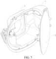
- a square locking groove 21 is provided on the cap 2 (as shown in FIG. 7 to FIG. 10 ).
- the rotary pin 200 can overcome the elastic force of the first elastic component 300 (by pressing the cap) to reach a closed position in the mounting box 100, and overcome the elastic force of the first elastic component 300 again (by pressing the cap) to move a short distance to automatically return to an open position under the elastic force of the first elastic component 300.
- the locking head 210 can be withdrawn from the square groove of the cap.
- the locking head 210 goes back into the square groove of the cap, and then rotated with the rotary pin 200 (usually by an angle of 90°), to form a nearly cross shape to achieve the closing and locking of the cap.
- the one end of the rocker arm 500 is driven to move, and consequently, the slidable pin 600 in the pin hole 510 at the other end of the rocker arm 500 slides in the guide groove 410 of the guide block 400.
- the rocker arm 500 fitting with the guide block 400 ensures that the cap can be opened and closed when a pressure is applied to the cap, and the cap cannot be opened and closed when a pulling force is applied to the cap.
- the pin hole 510 is arranged at the end of the rocker arm 500 that is fitted to the guide block 400, the slidable pin 600 that can move axially in the pin hole 510 and the adjusting component 700 configured to adjust the position of the slidable pin 600 are arranged.
- the slidable pin 600 is adjusted by the adjusting component 700 to persistently fit to the guide groove 410 of the guide block 400, such that even if the groove bottom of the guide groove 410 has bumps or unevennesses or has machining errors, the adjusting component 700 can also adjust the slidable pin 600 to a proper position, to fit the slidable pin 600 to the guide groove 410.
- the gap between the slidable pin 600 and the groove bottom of the guide groove 410 can be offset. Because the slidable pin 600 can move relative to the rocker arm 500, during the movement of the slidable pin 600, the rocker arm 500 will not sway or shift in an axial direction of an axis of rotation, ensuring the stability of the rocker arm 500, and ensuring that the rotary pin 200 can rotate, extend and retract effectively.
- the cap opening and closing device 1 according to the embodiment of the present invention has a stable structure, reliable performance and other advantages.
- the guide groove 410 may have a groove bottom with bumps or unevennesses, and the slidable pin 600 is adjusted by the adjusting component 700 to fit to the groove bottom of the guide groove 410.
- the groove bottom of the guide groove 410 has no bumps, to eliminate the swaying and shift of the rocker arm 500 caused by the machining or assembly errors of other components.
- a spring is provided at a rotation shaft in the middle of the rocker arm in the length direction.
- the rocker arm 500 sways with the shaft as a fulcrum in actual work (similar to a seesaw structure).
- the arrangement of the middle spring causes the rocker arm to shift or bounce in the direction that needs to be fixed (the radial direction of the shaft), causing ineffective rotation, extension and retraction of the rotary pin 200.
- the arrangement of the middle spring requires that the hole fitting with the rotating shaft is absolutely circular, causing difficulty in the machining of the mounting box.
- the rocker arm 500 is prevented from swaying or shifting in the axial direction of the axis of rotation, while not increasing the processing difficulty of the mounting box 100.
- the mounting box 100 includes a box body 110 and a box cover 120.
- the box body 110 is provided with an opening.
- the rotary pin 200 is rotatably and retractably mounted to the box body 110.
- the box cover 120 is mounted to the box body 110 and covers the opening.
- One end of the first elastic component 300 abuts against the rotary pin 200 and the other end abuts against the box cover 120.
- Both the guide block 400 and the rocker arm 500 are mounted to the box body 110 and the box cover 120. That is, the box body 110 and the box cover 120 are jointly provided with the guide block 400 and the rocker arm 500.
- the mounting box 100 has a split structure, to facilitate the overall disassembly and assembly of the cap opening and closing device 1.
- the box body 110 of the mounting box 100 is provided with a guide hole 115, the rotary pin 200 is fitted to the guide block 400, and the rotary pin 200 is retractable through the guide hole 115 and rotatable in the guide hole 115, to ensure the stability in the movement of the rotary pin 200, and facilitating the fitting with the cap.
- the rotary pin 200 is provided with a spiral guide groove 230, and the spiral guide groove 230 extends spirally on an outer peripheral surface of the rotary pin 200.
- the box body 110 of the mounting box 100 is provided with a pin pole 116, where the pin pole 116 fits to the spiral guide groove 230 and transforms the telescopic motion of the rotary pin 200 into a rotary motion.
- the fitting of the pin pole 116 with the spiral guide groove 230 makes the rotary pin 200 have a telescopic motion and a rotary motion in combination. That is, the extension and retraction of the rotary pin 200 is accompanied by the rotation itself, thereby driving the locking head 210 to rotate, to lock to and unlock from the cap.
- one end of the rotary pin 200 facing the box cover 120 is provided with a hollow hole 240, and the box cover 120 of the mounting box 100 is provided with a mounting post 123.
- the first elastic component 300 is a spring, one end of the first elastic component 300 is fitted in the hollow hole 240, and the other end of the first elastic component 300 is mounted around the mounting post 123, to fix the two ends of the first elastic component 300, so that the elastic force of the first elastic component 300 can stably push the rotary pin 200 out.
- the adjusting component 700 includes a second elastic component that pushes the slidable pin 600 toward the guide groove 410.
- the reciprocating sliding of the slidable pin 600 in its axial direction is enabled to drive the slidable pin 600 to slide along the guide groove 410, to fit the slidable pin 600 to the guide groove 410, and the movement of the slidable pin 600 will not drive the rocker arm 500 to shift or sway in the axial direction of the axis of rotation.
- the slidable pin 600 includes a pin cap 610610 and a pin pole 620.
- One end of the pin pole 620 is connected to the pin cap 610610, the cross-sectional area of the pin pole 620 is smaller than the cross-sectional area of the pin cap 610610, and the other end of the pin pole 620 is fitted to the guide groove 410 and is slidable along the guide groove 410.
- one end of the pin hole 510 facing the guide block 400 is structured with a step 520, and the pin cap 610610 abuts against the step 520 with the push of the second elastic component (that is, the adjusting component 700).
- the contact area between the second elastic component and the slidable pin 600 is increased, to allow for more uniform and stable force transmission; and on the other hand, the step 520 and the pin cap 610610 form a stop, to prevent the slidable pin 600 from getting out of the pin hole 510 in a direction toward the guide block 400.
- the cap opening and closing device 1 further includes an end cover 800.
- the end cover 800 is mounted to the other end of the rocker arm 500, and the end cover 800 covers the end of the pin hole 510 facing away from the guide block 400.
- the end cover 800 is mounted to the rocker arm 500 by a buckle structure, the second elastic component is arranged in the pin hole 510, one end of the second elastic component abuts against the end cover 800 and the other end abuts against the pin cap 610610 of the slidable pin 600.
- the surface of the end cover 800 facing the second elastic component is provided with a positioning protrusion 810, and the positioning protrusion 810 extends into the pin hole 510.
- the second elastic component is a spring, and one end of the second elastic component is mounted around the positioning protrusion 810, to fix the second elastic component, and ensure the stability of the force.
- the surface of the end cover 800 facing away from the second elastic component is provided with a first spherical surface 820, and a stop plate 117 is provided in the box body 110 of the mounting box 100, where the first spherical surface 820 abuts against the stop plate 117, to limit the movement of the second elastic component in the axial direction, and eliminate the swaying of the rocker arm 500 caused by the reaction force of the second elastic component, thus further enhancing the stability of the rocker arm 500.
- the rocker arm 500 is an integral rigid component formed, for example, by integral injection molding of plastics, which has simple structure, is easy to produce and process, and is maintained stable. Alternatively, it can also be integrally formed by a metal member, which is easy to process and has stable structure as well.
- the end of the rocker arm that is fitted to the guide block is arranged to have a flexible structure
- the end of the rocker arm that is fitted to the rotary pin is arranged to have a rigid structure.
- the flexible structure is difficult to process, and the rocker arm is always in a state of deformation due to the essential mechanical support, raising a high requirement for the selection of materials.
- the rigid end of the rocker arm will always bear a reaction force that alternates repeatedly (the magnitude of the force varies), causing the rocker arm to shift or sway in the direction that needs to be fixed (the radial direction of the rotating shaft). As a result, the rotary pin cannot rotate, extend and retract effectively.
- the rocker arm 500 with an integral rigid structure is used in combination with the slidable pin 600 and the adjusting component 700, which eliminates the swaying and shift of the rocker arm 500 in the axial direction of the axis of rotation, is easy to process, and has low requirements for the materials.
- the rocker arm 500 is respectively provided with a first rotating shaft 530 and a second rotating shaft 540 at two sides of a middle portion in the length direction, and the central axis of the first rotating shaft 530 coincides with the central axis of the second rotating shaft 540 and is perpendicular to the extension and retraction direction of the rotary pin 200.
- the mounting box 100 is provided with a first shaft hole 101 and a second shaft hole 102, where the first rotating shaft 530 is rotatably fitted in the first shaft hole 101, and the second rotating shaft 540 is rotatably fitted in the second shaft hole 102, to rotatably mount the rocker arm 500 to the mounting box 100.
- the end of the first rotating shaft 530 facing away from the rocker arm 500 and the end of the second rotating shaft 540 facing away from the rocker arm 500 are respectively provided with a second spherical surface 550.
- the second spherical surface 550 of the first rotating shaft 530 and the second spherical surface 550 of the second rotating shaft 540 abut against the mounting box 100, respectively. Therefore, the rocker arm 500 can be positioned in the axial direction of the first rotating shaft 530 and the second rotating shaft 540, to further prevent the rocker arm 500 to sway in the axial direction of the axis of rotation.
- one of two opposite side walls of the mounting box 100 is provided with a first mounting seat 111 and a second mounting seat 112, and the other is provided with a first mounting arm 121 and a second mounting arm 122.
- the first mounting seat 111 and the second mounting seat 112 are provided on the box body 110
- the first mounting arm 121 and the second mounting arm 122 are provided on the box cover 120.
- the first mounting arm 121 and the first mounting seat 111 together define the first shaft hole 101
- the second mounting arm 122 and the second mounting seat 112 together define second shaft hole 102.
- the second spherical surface 550 of the first rotating shaft 530 abuts against the first mounting seat 111
- the second spherical surface 550 of the second rotating shaft 540 abuts against the second mounting seat 112.
- the one end of the rocker arm 500 is provided with a fork-shaped head 560, and the fork-shaped head 560 is provided with oppositely arranged guide posts 561.
- An outer peripheral surface of the rotary pin 200 is provided with an annular groove 220 extending circumferentially, and the guide post 561 is fitted in the annular groove 220. Therefore, when the rotary pin 200 is extended and retracted, the rocker arm 500 is driven to sway about its axis of rotation, and the fork-shaped head 560 and the rotary pin 200 are formed to be rotatably fitted in two directions.
- the fork-shaped head 560 can rotate relative to the rotary pin 200 around the axial direction of the guide post 561, and in the other direction, the rotary pin 200 can rotate relative to the fork-shaped head 560 around its own axial direction. Therefore, the fitting of the fork-shaped head 560 and the rotary pin 200 will not hinder the extension, retraction and rotation of the rotary pin 200 itself.
- a first stopper 113 and a second stopper 114 are provided in the box body 110 of the mounting box 100, and the first stopper 113 and the second stopper 114 can be oppositely arranged in the radial direction of the guide hole 115.
- the fork-shaped head 560 is located between the first stopper 113 and the second stopper 114, to prevent the fork-shaped head 560 of the rocker arm 500 from swaying in the radial direction of the rotary pin 200.
- the guide block 400 is provided with a support shaft 420, and mounting box 100 is provided with a support shaft hole 124, where the support shaft 420 is fitted in the support shaft hole 124.
- the guide block 400 is rotatably mounted to the mounting box 100.
- the support shaft hole 124 includes two parts respectively provided on the box body 110 and the box cover 120, and a complete support shaft hole 124 is formed after the box body 110 and the box cover 120 are assembled.
- the guide groove 410 is structured to have a closed annular structure, for example, an inverted heart shape.
- the slidable pin 600 can slide unidirectionally along the guide groove 410.
- the arrow in the guide groove 410 in FIG. 6 shows the unidirectional sliding direction of the slidable pin 600.
- the guide groove 410 includes a first ascending section 411, a first descending section 412, a second ascending section 413 and a second descending section 414 connected in sequence.
- One end of the first ascending section 411 is connected to one end of the first descending section 412, and the distance between the first ascending section 411 and the first descending section 412 gradually increases toward the extending-out direction of the rotary pin 200.
- One end of the second ascending section 413 is connected to the other end of the first descending section 412, one end of the second descending section 414 is connected to the other end of the first ascending section 411, the other end of the second ascending section 413 is connected to the other end of the second descending section 414, and the distance between the second ascending section 413 and the second descending section 414 gradually increases toward the extending-out direction of the rotary pin 200.
- the reciprocating sliding of the slidable pin 600 in its axial direction is enabled to drive the slidable pin 600 to slide along the guide groove 410 through the elastic force of the second elastic component, so as to fit the slidable pin 600 to the guide groove 410.
- a press type cap opening and closing device is formed. That is, the cap cannot be opened and closed by applying a pulling force.
- the slidable pin 600 slides to a position between the second ascending section 413 and the second descending section 414, where a V-shaped structure is formed.
- the slidable pin 600 is pressed against the V-shaped structure by the adjusting component 700, and is in balance and unable to slide continuously.
- the rotary pin 200 drives the slidable pin 600 to slide a short distance toward one side of the V-shaped structure (lower left in FIG. 6 ) through the rocker arm 500, and then the slidable pin 600 is forced by the first elastic component 300 to slide continuously, to reach an open position of the cap.
- the slidable pin 600 is stopped by the V-shaped structure and unable to move, so the cap cannot be opened.
- the cap opening and closing device 1 further includes a motor 910 and a locking block 920.
- the motor 910 is mounted to the box body 110 of the mounting box 100.
- the locking block 920 is in transmission connection with the motor 910, and the rotary pin 200 is provided with a locking groove 250, where the locking block 920 is driven by the motor 910 to move into and out of the locking groove 250.
- the motor 910 can drive the locking block 920 to move into the locking groove 250 of the rotary pin 200.
- the rotary pin 200 cannot be rotated, extended, and retracted, to prevent the cap from being opened by mistake.
- the motor 910 is in transmission connection with the locking block 920 through a screw 930.
- the screw 930 transforms the rotary motion of a motor shaft of the motor 910 into the linear motion of the locking block 920, to save space in the mounting box 100, and thus reduce the volume of the cap opening and closing device 1.
- a vehicle according to an embodiment of the present invention is described with reference to FIG. 7 to FIG. 10 below.
- the vehicle according to the embodiment of the present invention includes a cap 2 and the cap opening and closing device 1 according to the above-mentioned embodiment of the present invention.
- the cap 2 can be provided on an open box 3 with an open one end, where the open box 3 can be a fuel tank and/or a charging box of the vehicle.
- the cap may be an oil filler cap, and/or a charging port cap.
- the cap opening and closing device 1 is applicable to an oil filler cap, and a charging port cap.
- both the oil filler cap and the charging port cap can be used with the cap opening and closing device 1 according to the embodiment of the present invention.
- a locking groove 21 is provided on the cap 2, where the locking head 210 provided at one end of the rotary pin 200 can be removably fitted in the locking groove 21, to removably connect the cap opening and closing device 1 to the cap 2.
- the locking groove 21 is a square groove.
- the vehicle according to the embodiment of the present invention has the advantages of reliable cap opening and closing performance by utilizing the cap opening and closing device 1 according to the embodiment of the present invention.
Abstract
Description
- The present disclosure claims priority to
Chinese Patent Application No. "202020718710.9" filed by BYD Company Limited on April 30, 2020 - The present invention relates to a cap opening and closing device and a vehicle having the cap opening and closing device.
- A cap opening and closing device in the related art is locked by pressing by an external force and opened by pressing it again. The cap opening and closing device mainly include a mounting box, a rotary pin, a rocker arm, a guide block, and other components. A guide groove is arranged in the guide block, where one end of the rocker arm is fitted to the rotary pin, and the other end of the rocker arm is fitted to the guide groove. However, since the guide groove has a groove bottom with bumps or unevennesses, the rocker arm will sway or shift in an axial direction of an axis of rotation when the rocker arm is fitted thereto, causing ineffective rotation, extension and retraction of the rotary pin, thereby affecting the performance reliability.
- The present invention aims to at least solves one of the technical problems in the related art. To this end, an object of the present invention is to propose a cap opening and closing device having stable structure, reliable performance and other advantages.
- The present invention also proposes a vehicle having the cap opening and closing device.
- An embodiment according to a first aspect of the present invention discloses a cap opening and closing device, which includes: a mounting box; a locking pin, rotatably and retractably mounted to the mounting box, and having a locking head for hooking the cap; a first elastic component, configured to push a rotary pin out of the mounting box; a guide block, mounted to the mounting box, and provided with a guide groove; a rocker arm, rotatably mounted to the mounting box, and having one end fitted to the locking pin and the other end fitted with a pin hole; a slidable pin, movably fitted in the pin hole along an axial direction of the pin hole; and an adjusting component, arranged on the other end of the rocker arm and abutting against the slidable pin, and configured to adjust the position of the slidable pin in the pin hole, where the slidable pin is adjusted by the adjusting component to fit to the guide groove and slide along the guide groove.
- The cap opening and closing device according to the embodiment of the present invention has a stable structure, reliable performance and other advantages.
- According to some specific embodiments of the present invention, the guide groove has a groove bottom with bumps or unevennesses, and the slidable pin is adjusted by the adjusting component to fit to the groove bottom of the guide groove.
- According to some specific embodiments of the present invention, the adjusting component includes a second elastic component configured to push the slidable pin toward the guide groove.
- According to some specific embodiments of the present invention, the slidable pin includes a pin cap; and a pin pole, where one end of the pin pole is connected to the pin cap, the cross-sectional area of the pin pole is smaller than the cross-sectional area of the pin cap, and the other end of the pin pole is fitted to the guide groove and is slidable along the guide groove
- Further, the pin hole is structured to have a step, and the pin cap is structured to persistently abut against the step with the push of the second elastic component.
- According to some specific embodiments of the present invention, the cap opening and closing device further includes an end cover, where the end cover is mounted to the other end of the rocker arm and covers the pin hole. The second elastic component is arranged in the pin hole, and one end of the second elastic component abuts against the end cover and the other end abuts against the slidable pin.
- According to some specific embodiments of the present invention, the surface of the end cover facing the second elastic component is provided with a positioning protrusion, and the second elastic component is a spring, where the one end of the second elastic component is mounted around the positioning protrusion.
- According to some specific embodiments of the present invention, the surface of the end cover facing away from the second elastic component is provided with a first spherical surface, and a stop plate is provided in the mounting box, where the first spherical surface abuts against the stop plate.
- According to some specific embodiments of the present invention, the rocker arm is an integral rigid component.
- According to some specific embodiments of the present invention, the rocker arm is respectively provided with a first rotating shaft and a second rotating shaft at two sides of a middle portion in the length direction, and the mounting box is provided with a first shaft hole and a second shaft hole, where the first rotating shaft is rotatably fitted in the first shaft hole, and the second rotating shaft is rotatably fitted in the second shaft hole.
- According to some specific embodiments of the present invention, the end of the first rotating shaft facing away from the rocker arm and the end of the second rotating shaft facing away from the rocker arm are respectively provided with a second spherical surface, where the second spherical surface of the first rotating shaft and the second spherical surface of the second rotating shaft respectively abut against the mounting box.
- According to some specific embodiments of the present invention, one of two opposite side walls of the mounting box is provided with a first mounting seat and a second mounting seat, and the other is provided with a first mounting arm and a second mounting arm. The first mounting arm and the first mounting seat together define the first shaft hole, and the second mounting arm and the second mounting seat together define the second shaft hole. The second spherical surface of the first rotating shaft abuts against the first mounting seat, and the second spherical surface of the second rotating shaft abuts against the second mounting seat.
- According to some specific embodiments of the present invention, the locking pin includes: a rotary pin, rotatably and retractably mounted to the mounting box; and a first elastic component configured to push the rotary pin to extend out of the mounting box.
- Further, the one end of the rocker arm is provided with a fork-shaped head, and the fork-shaped head is provided with oppositely arranged guide posts. An outer peripheral surface of the rotary pin is provided with an annular groove extending circumferentially, and the guide posts are fitted in the annular groove.
- According to some specific embodiments of the present invention, a first stopper and a second stopper are provided in the mounting box, where the fork-shaped head is located between the first stopper and the second stopper.
- According to some specific embodiments of the present invention, the guide groove is structured to have a closed annular structure, where the slidable pin can slide unidirectionally along the guide groove. The guide groove includes a first ascending section, a first descending section, a second ascending section, and a second descending section connected in sequence. One end of the first ascending section is connected to one end of the first descending section, and the distance between the first ascending section and the first descending section gradually increases toward the extending-out direction of the locking pin. One end of the second ascending section is connected to the other end of the first descending section, one end of the second descending section is connected to the other end of the first ascending section, the other end of the second ascending section is connected to the other end of the second descending section, and the distance between the second ascending section and the second descending section gradually increases toward the extending direction of the locking pin.
- According to some specific embodiments of the present invention, the cap opening and closing device also includes: a motor, where the motor is
- According to some specific embodiments of the present invention, the mounting box includes: a box body, where the locking pin is rotatably and retractably mounted to the box body; and a box cover, mounted to the box body, where one end of the first elastic component abuts against the locking pin and the other end abuts against the box cover, and both the guide block and the rocker arm are mounted to the box body and the box cover.
- An embodiment according to a second aspect of the present invention proposes a vehicle, which includes a cap, having a locking groove thereon; and a cap opening and closing device according to the embodiment in accordance with the first aspect of the present invention, where a locking head on a locking pin of the cap opening and closing device is fitted to the locking groove to connect the cap opening and closing device to the cap.
- The vehicle according to the embodiment of the present invention has the advantages of reliable cap opening and closing performance by virtue of the cap opening and closing device according to the embodiment in accordance with the first aspect of the present invention.
- According to some specific embodiments of the present invention, the cap is an oil filler cap; and/or the cap is a charging port cap.
- Additional aspects and advantages of the present invention will be partly given in and partly apparent from the description below, or understood through practice of the present invention.
- The above and/or other additional aspects and advantages of the present invention become apparent and comprehensible from the description of embodiments in connection with accompanying drawings, in which:
-
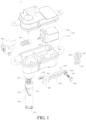
FIG. 1 is an exploded view of a cap opening and closing device according to an embodiment of the present invention. -
FIG. 2 is a schematic partial structural view of a cap opening and closing device according to an embodiment of the present invention. -
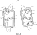
FIG. 3 is an exploded view of a mounting box of a cap opening and closing device according to an embodiment of the present invention. -
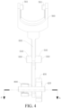
FIG. 4 is a schematic view showing a rocker arm fitting with a guide block of a cap opening and closing device according to an embodiment of the present invention. -
FIG. 5 is a schematic cross-sectional view taken along the line A-A inFIG. 4 . -
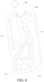
FIG. 6 is a schematic structural view of a guide block of a cap opening and closing device according to an embodiment of the present invention. -
FIG. 7 is a schematic three-dimensional view showing a cap fitting with a cap opening and closing device according to an embodiment of the present invention, where the cap is open. -
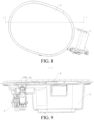
FIG. 8 is a schematic top view showing a cap fitting with a cap opening and closing device according to an embodiment of the present invention, where, the cap is closed. -
FIG. 9 is a schematic cross-sectional view taken along A-A inFIG. 8 . -
FIG. 10 is a schematic cross-sectional view taken along A-A inFIG. 8 where the cap is open. -
- 1 cap opening and closing device,
- 100 mounting box, 101 first shaft hole, 102 second shaft hole, 110 box body, 111 first mounting seat, 112 second mounting seat, 113 first stopper, 114 second stopper, 115 guide hole, 116 pin pole, 117 stop plate, 120 box cover, 121 first mounting arm, 122 second mounting arm, 123 mounting post, 124 support shaft hole,
- 200 rotary pin, 210 locking head, 220 annular groove, 230 spiral guide groove, 240 hollow hole, 250 locking groove,
- 300 first elastic component,
- 400 guide block, 410 guide groove, 411 first ascending section, 412 first descending section, 413 second ascending section, 414 second descending section, 420 support shaft,
- 500 rocker arm, 510 pin hole, 520 step, 530 first rotating shaft, 540 second rotating shaft, 550 second spherical surface, 560 fork-shaped head, 561 guide post,
- 600 slidable pin, 610 pin cap, 620 pin pole,
- 700 adjusting component,
- 800 end cover, 810 positioning protrusion, 820 first spherical surface,
- 910 motor, 920 locking block, 930 screw,
- 2 cap, 21 locking groove, 3 open box.
- Embodiments of the present invention are described in detail below, and examples of the embodiments are shown in the accompanying drawings, where the same or similar elements or the elements having same or similar functions are denoted by the same or similar reference numerals throughout the description. The following embodiments described with reference to the accompanying drawings are exemplary, and are merely intended to describe the present invention and cannot be construed as a limitation to the present invention as defined in the appended claims.
- In the description of the present invention, it should be understood that orientation or position relationships indicated by the terms such as "center", "length", "width", "thickness", "top", "bottom", "inside", "outside", "axial", "radial", and "circumferential" are based on orientation or position relationships shown in the accompanying drawings, and are used only for ease and brevity of illustration and description, rather than indicating or implying that the mentioned apparatus or component need to have a particular orientation or need to be constructed and operated in a particular orientation. Therefore, such terms should not be construed as limiting of the present invention.
- In the description of the present invention, "first feature", and "second feature" may include one or more of the features, "a number of" means two or more, and "several" means one or more.
- A cap opening and
closing device 1 according to an embodiment of the present invention is described with reference to accompanying drawings. - As shown in
FIG. 1 to FIG. 6 , the cap opening andclosing device 1 according to an embodiment of the present invention includes a mountingbox 100 locking pin, a firstelastic component 300, aguide block 400, arocker arm 500, aslidable pin 600 and anadjusting component 700. - The locking pin is rotatably and retractably mounted to the mounting
box 100. Optionally, as shown inFIG. 1 , The locking pin includes arotary pin 220 and a firstelastic component 300. Therotary pin 200 is rotatably and retractably mounted to the mountingbox 100, and therotary pin 200 has a lockinghead 210 for hooking acap 2 at one end. The firstelastic component 300 is configured to push therotary pin 200 to extend out of the mountingbox 100, and the firstelastic component 300 is respectively connected to therotary pin 200 and the mountingbox 100. - The
guide block 400 is mounted to the mountingbox 100, and theguide block 400 is provided with aguide groove 410. Therocker arm 500 is rotatably mounted to the mountingbox 100. For example, a middle portion of therocker arm 500 in a length direction is rotatably mounted to the mountingbox 100, and an axis of rotation of therocker arm 500 is perpendicular to the extension and retraction direction of therotary pin 200. One end of therocker arm 500 is fitted to therotary pin 200, and the other end of therocker arm 500 is provided with apin hole 510, where an axial direction of thepin hole 510 is perpendicular to theguide groove 410 of theguide block 400. Theslidable pin 600 is movably fitted in thepin hole 510 along the axial direction of thepin hole 510. The adjustingcomponent 700 is arranged at the other end of therocker arm 500 and abuts against theslidable pin 600. The adjustingcomponent 700 is configured to adjust the position of theslidable pin 600 in thepin hole 510, and theslidable pin 600 is adjusted by the adjustingcomponent 700 to fit to theguide groove 410 and slide along theguide groove 410. - For example, the cap opening and
closing device 1 may be a press type cap opening and closing device, that is, a push-push type cap opening and closing device. The lockinghead 210 of therotary pin 200 may have a square structure. Correspondingly, asquare locking groove 21 is provided on the cap 2 (as shown inFIG. 7 to FIG. 10 ). Therotary pin 200 can overcome the elastic force of the first elastic component 300 (by pressing the cap) to reach a closed position in themounting box 100, and overcome the elastic force of the firstelastic component 300 again (by pressing the cap) to move a short distance to automatically return to an open position under the elastic force of the firstelastic component 300. - When the
rotary pin 200 is at the open position, the lockinghead 210 can be withdrawn from the square groove of the cap. When therotary pin 200 is in the closed position, the lockinghead 210 goes back into the square groove of the cap, and then rotated with the rotary pin 200 (usually by an angle of 90°), to form a nearly cross shape to achieve the closing and locking of the cap. - During the extension and retraction of the
rotary pin 200, the one end of therocker arm 500 is driven to move, and consequently, theslidable pin 600 in thepin hole 510 at the other end of therocker arm 500 slides in theguide groove 410 of theguide block 400. Therocker arm 500 fitting with theguide block 400 ensures that the cap can be opened and closed when a pressure is applied to the cap, and the cap cannot be opened and closed when a pulling force is applied to the cap. - In the cap opening and
closing device 1 according to the embodiment of the present invention, thepin hole 510 is arranged at the end of therocker arm 500 that is fitted to theguide block 400, theslidable pin 600 that can move axially in thepin hole 510 and theadjusting component 700 configured to adjust the position of theslidable pin 600 are arranged. Theslidable pin 600 is adjusted by the adjustingcomponent 700 to persistently fit to theguide groove 410 of theguide block 400, such that even if the groove bottom of theguide groove 410 has bumps or unevennesses or has machining errors, the adjustingcomponent 700 can also adjust theslidable pin 600 to a proper position, to fit theslidable pin 600 to theguide groove 410. Therefore, by adjusting the position of theslidable pin 600 by the adjustingcomponent 700, the gap between theslidable pin 600 and the groove bottom of theguide groove 410 can be offset. Because theslidable pin 600 can move relative to therocker arm 500, during the movement of theslidable pin 600, therocker arm 500 will not sway or shift in an axial direction of an axis of rotation, ensuring the stability of therocker arm 500, and ensuring that therotary pin 200 can rotate, extend and retract effectively. - Therefore, the cap opening and
closing device 1 according to the embodiment of the present invention has a stable structure, reliable performance and other advantages. - It can be understood by those skilled in the art that the
guide groove 410 may have a groove bottom with bumps or unevennesses, and theslidable pin 600 is adjusted by the adjustingcomponent 700 to fit to the groove bottom of theguide groove 410. Definitely, according to an embodiment of the present invention, it is also applicable in a case where the groove bottom of theguide groove 410 has no bumps, to eliminate the swaying and shift of therocker arm 500 caused by the machining or assembly errors of other components. - In addition, it is to be understood that in some cap opening and closing devices in related art, a spring is provided at a rotation shaft in the middle of the rocker arm in the length direction. However, because the force bearing point of the
rocker arm 500 is located at the end fitting to therotary pin 200, therocker arm 500 sways with the shaft as a fulcrum in actual work (similar to a seesaw structure). The arrangement of the middle spring causes the rocker arm to shift or bounce in the direction that needs to be fixed (the radial direction of the shaft), causing ineffective rotation, extension and retraction of therotary pin 200. Moreover, the arrangement of the middle spring requires that the hole fitting with the rotating shaft is absolutely circular, causing difficulty in the machining of the mounting box. - In the cap opening and
closing device 1 according to the embodiment of the present invention, by arranging theslidable pin 600 and theadjusting component 700 at the end of therocker arm 500 that fits with theguide block 400, therocker arm 500 is prevented from swaying or shifting in the axial direction of the axis of rotation, while not increasing the processing difficulty of the mountingbox 100. - In some specific embodiments of the present invention, as shown in
FIG. 1 andFIG. 3 , the mountingbox 100 includes abox body 110 and abox cover 120. - One side of the
box body 110 is provided with an opening. Therotary pin 200 is rotatably and retractably mounted to thebox body 110. Thebox cover 120 is mounted to thebox body 110 and covers the opening. One end of the firstelastic component 300 abuts against therotary pin 200 and the other end abuts against thebox cover 120. Both theguide block 400 and therocker arm 500 are mounted to thebox body 110 and thebox cover 120. That is, thebox body 110 and thebox cover 120 are jointly provided with theguide block 400 and therocker arm 500. As such, the mountingbox 100 has a split structure, to facilitate the overall disassembly and assembly of the cap opening andclosing device 1. - In some specific embodiments of the present invention, as shown in
FIG. 3 , thebox body 110 of the mountingbox 100 is provided with aguide hole 115, therotary pin 200 is fitted to theguide block 400, and therotary pin 200 is retractable through theguide hole 115 and rotatable in theguide hole 115, to ensure the stability in the movement of therotary pin 200, and facilitating the fitting with the cap. - In an embodiment, as shown in
FIG. 1 andFIG. 3 , therotary pin 200 is provided with aspiral guide groove 230, and thespiral guide groove 230 extends spirally on an outer peripheral surface of therotary pin 200. Thebox body 110 of the mountingbox 100 is provided with apin pole 116, where thepin pole 116 fits to thespiral guide groove 230 and transforms the telescopic motion of therotary pin 200 into a rotary motion. In other words, the fitting of thepin pole 116 with thespiral guide groove 230 makes therotary pin 200 have a telescopic motion and a rotary motion in combination. That is, the extension and retraction of therotary pin 200 is accompanied by the rotation itself, thereby driving the lockinghead 210 to rotate, to lock to and unlock from the cap. - In some specific embodiments of the present invention, as shown in
FIG. 1 to FIG. 3 , one end of therotary pin 200 facing thebox cover 120 is provided with ahollow hole 240, and thebox cover 120 of the mountingbox 100 is provided with a mountingpost 123. The firstelastic component 300 is a spring, one end of the firstelastic component 300 is fitted in thehollow hole 240, and the other end of the firstelastic component 300 is mounted around the mountingpost 123, to fix the two ends of the firstelastic component 300, so that the elastic force of the firstelastic component 300 can stably push therotary pin 200 out. - In some specific embodiments of the present invention, the adjusting
component 700 includes a second elastic component that pushes theslidable pin 600 toward theguide groove 410. Through the elastic force of the second elastic component, the reciprocating sliding of theslidable pin 600 in its axial direction is enabled to drive theslidable pin 600 to slide along theguide groove 410, to fit theslidable pin 600 to theguide groove 410, and the movement of theslidable pin 600 will not drive therocker arm 500 to shift or sway in the axial direction of the axis of rotation. - In an embodiment, as shown in
FIG. 5 , theslidable pin 600 includes a pin cap 610610 and apin pole 620. One end of thepin pole 620 is connected to the pin cap 610610, the cross-sectional area of thepin pole 620 is smaller than the cross-sectional area of the pin cap 610610, and the other end of thepin pole 620 is fitted to theguide groove 410 and is slidable along theguide groove 410. Optionally, one end of thepin hole 510 facing theguide block 400 is structured with astep 520, and the pin cap 610610 abuts against thestep 520 with the push of the second elastic component (that is, the adjusting component 700). - Therefore, on the one hand, the contact area between the second elastic component and the
slidable pin 600 is increased, to allow for more uniform and stable force transmission; and on the other hand, thestep 520 and the pin cap 610610 form a stop, to prevent theslidable pin 600 from getting out of thepin hole 510 in a direction toward theguide block 400. - In some specific embodiments of the present invention, as shown in
FIG. 1 ,FIG. 4 andFIG. 5 , the cap opening andclosing device 1 further includes anend cover 800. - The
end cover 800 is mounted to the other end of therocker arm 500, and theend cover 800 covers the end of thepin hole 510 facing away from theguide block 400. For example, theend cover 800 is mounted to therocker arm 500 by a buckle structure, the second elastic component is arranged in thepin hole 510, one end of the second elastic component abuts against theend cover 800 and the other end abuts against the pin cap 610610 of theslidable pin 600. - In an embodiment, as shown in
FIG. 5 , the surface of theend cover 800 facing the second elastic component is provided with apositioning protrusion 810, and thepositioning protrusion 810 extends into thepin hole 510. The second elastic component is a spring, and one end of the second elastic component is mounted around thepositioning protrusion 810, to fix the second elastic component, and ensure the stability of the force. - In an embodiment, as shown in
FIG. 5 , the surface of theend cover 800 facing away from the second elastic component is provided with a firstspherical surface 820, and astop plate 117 is provided in thebox body 110 of the mountingbox 100, where the firstspherical surface 820 abuts against thestop plate 117, to limit the movement of the second elastic component in the axial direction, and eliminate the swaying of therocker arm 500 caused by the reaction force of the second elastic component, thus further enhancing the stability of therocker arm 500. - In some specific embodiments of the present invention, the
rocker arm 500 is an integral rigid component formed, for example, by integral injection molding of plastics, which has simple structure, is easy to produce and process, and is maintained stable. Definitely, it can also be integrally formed by a metal member, which is easy to process and has stable structure as well. - In some cap opening and closing devices in related art, the end of the rocker arm that is fitted to the guide block is arranged to have a flexible structure, and the end of the rocker arm that is fitted to the rotary pin is arranged to have a rigid structure. In this case, the flexible structure is difficult to process, and the rocker arm is always in a state of deformation due to the essential mechanical support, raising a high requirement for the selection of materials. Moreover, the rigid end of the rocker arm will always bear a reaction force that alternates repeatedly (the magnitude of the force varies), causing the rocker arm to shift or sway in the direction that needs to be fixed (the radial direction of the rotating shaft). As a result, the rotary pin cannot rotate, extend and retract effectively.
- In the cap opening and
closing device 1 according to the embodiment of the present invention, therocker arm 500 with an integral rigid structure is used in combination with theslidable pin 600 and theadjusting component 700, which eliminates the swaying and shift of therocker arm 500 in the axial direction of the axis of rotation, is easy to process, and has low requirements for the materials. - In some specific embodiments of the present invention, as shown in
FIG. 1 to FIG. 4 , therocker arm 500 is respectively provided with a firstrotating shaft 530 and a secondrotating shaft 540 at two sides of a middle portion in the length direction, and the central axis of the firstrotating shaft 530 coincides with the central axis of the secondrotating shaft 540 and is perpendicular to the extension and retraction direction of therotary pin 200. The mountingbox 100 is provided with afirst shaft hole 101 and asecond shaft hole 102, where the firstrotating shaft 530 is rotatably fitted in thefirst shaft hole 101, and the secondrotating shaft 540 is rotatably fitted in thesecond shaft hole 102, to rotatably mount therocker arm 500 to the mountingbox 100. - As shown in
FIG. 4 , the end of the firstrotating shaft 530 facing away from therocker arm 500 and the end of the secondrotating shaft 540 facing away from therocker arm 500 are respectively provided with a secondspherical surface 550. The secondspherical surface 550 of the firstrotating shaft 530 and the secondspherical surface 550 of the secondrotating shaft 540 abut against the mountingbox 100, respectively. Therefore, therocker arm 500 can be positioned in the axial direction of the firstrotating shaft 530 and the secondrotating shaft 540, to further prevent therocker arm 500 to sway in the axial direction of the axis of rotation. - In an embodiment, as shown in
FIG. 3 , one of two opposite side walls of the mountingbox 100 is provided with a first mountingseat 111 and a second mountingseat 112, and the other is provided with a first mounting arm 121 and asecond mounting arm 122. For example, the first mountingseat 111 and the second mountingseat 112 are provided on thebox body 110, and the first mounting arm 121 and thesecond mounting arm 122 are provided on thebox cover 120. The first mounting arm 121 and the first mountingseat 111 together define thefirst shaft hole 101, and thesecond mounting arm 122 and the second mountingseat 112 together definesecond shaft hole 102. The secondspherical surface 550 of the firstrotating shaft 530 abuts against the first mountingseat 111, and the secondspherical surface 550 of the secondrotating shaft 540 abuts against the second mountingseat 112. - In some specific embodiments of the present invention, as shown in
FIG. 1 ,FIG. 2 , andFIG. 4 , the one end of therocker arm 500 is provided with a fork-shapedhead 560, and the fork-shapedhead 560 is provided with oppositely arranged guide posts 561. An outer peripheral surface of therotary pin 200 is provided with anannular groove 220 extending circumferentially, and theguide post 561 is fitted in theannular groove 220. Therefore, when therotary pin 200 is extended and retracted, therocker arm 500 is driven to sway about its axis of rotation, and the fork-shapedhead 560 and therotary pin 200 are formed to be rotatably fitted in two directions. In one direction, the fork-shapedhead 560 can rotate relative to therotary pin 200 around the axial direction of theguide post 561, and in the other direction, therotary pin 200 can rotate relative to the fork-shapedhead 560 around its own axial direction. Therefore, the fitting of the fork-shapedhead 560 and therotary pin 200 will not hinder the extension, retraction and rotation of therotary pin 200 itself. - In an embodiment, as shown in
FIG. 3 , afirst stopper 113 and asecond stopper 114 are provided in thebox body 110 of the mountingbox 100, and thefirst stopper 113 and thesecond stopper 114 can be oppositely arranged in the radial direction of theguide hole 115. The fork-shapedhead 560 is located between thefirst stopper 113 and thesecond stopper 114, to prevent the fork-shapedhead 560 of therocker arm 500 from swaying in the radial direction of therotary pin 200. - In some specific embodiments of the present invention, as shown in
FIG. 1 to FIG. 3 , theguide block 400 is provided with asupport shaft 420, and mountingbox 100 is provided with asupport shaft hole 124, where thesupport shaft 420 is fitted in thesupport shaft hole 124. As such, theguide block 400 is rotatably mounted to the mountingbox 100. - For example, the
support shaft hole 124 includes two parts respectively provided on thebox body 110 and thebox cover 120, and a completesupport shaft hole 124 is formed after thebox body 110 and thebox cover 120 are assembled. - In some specific embodiments of the present invention, as shown in
FIG. 6 , theguide groove 410 is structured to have a closed annular structure, for example, an inverted heart shape. Theslidable pin 600 can slide unidirectionally along theguide groove 410. The arrow in theguide groove 410 inFIG. 6 shows the unidirectional sliding direction of theslidable pin 600. Specifically, theguide groove 410 includes afirst ascending section 411, afirst descending section 412, asecond ascending section 413 and asecond descending section 414 connected in sequence. One end of thefirst ascending section 411 is connected to one end of thefirst descending section 412, and the distance between thefirst ascending section 411 and thefirst descending section 412 gradually increases toward the extending-out direction of therotary pin 200. One end of thesecond ascending section 413 is connected to the other end of thefirst descending section 412, one end of thesecond descending section 414 is connected to the other end of thefirst ascending section 411, the other end of thesecond ascending section 413 is connected to the other end of thesecond descending section 414, and the distance between thesecond ascending section 413 and thesecond descending section 414 gradually increases toward the extending-out direction of therotary pin 200. Therefore, by arranging theguide groove 410 of the above shape, the reciprocating sliding of theslidable pin 600 in its axial direction is enabled to drive theslidable pin 600 to slide along theguide groove 410 through the elastic force of the second elastic component, so as to fit theslidable pin 600 to theguide groove 410. In other words, by limiting the extension and retraction of therotary pin 200 by therocker arm 500, a press type cap opening and closing device is formed. That is, the cap cannot be opened and closed by applying a pulling force. - For example, when the cap is in a closed position, the
slidable pin 600 slides to a position between thesecond ascending section 413 and thesecond descending section 414, where a V-shaped structure is formed. Theslidable pin 600 is pressed against the V-shaped structure by the adjustingcomponent 700, and is in balance and unable to slide continuously. Only when the cap is pressed, therotary pin 200 drives theslidable pin 600 to slide a short distance toward one side of the V-shaped structure (lower left inFIG. 6 ) through therocker arm 500, and then theslidable pin 600 is forced by the firstelastic component 300 to slide continuously, to reach an open position of the cap. In other words, when the cap is closed and a pulling force is applied to the cap, theslidable pin 600 is stopped by the V-shaped structure and unable to move, so the cap cannot be opened. - In some specific embodiments of the present invention, as shown in
FIG. 1 andFIG. 2 , the cap opening andclosing device 1 further includes amotor 910 and alocking block 920. - The
motor 910 is mounted to thebox body 110 of the mountingbox 100. Thelocking block 920 is in transmission connection with themotor 910, and therotary pin 200 is provided with a lockinggroove 250, where thelocking block 920 is driven by themotor 910 to move into and out of the lockinggroove 250. As such, when the cap is closed, themotor 910 can drive the lockingblock 920 to move into the lockinggroove 250 of therotary pin 200. At this time, therotary pin 200 cannot be rotated, extended, and retracted, to prevent the cap from being opened by mistake. - In an embodiment, the
motor 910 is in transmission connection with thelocking block 920 through ascrew 930. Thescrew 930 transforms the rotary motion of a motor shaft of themotor 910 into the linear motion of thelocking block 920, to save space in themounting box 100, and thus reduce the volume of the cap opening andclosing device 1. - A vehicle according to an embodiment of the present invention is described with reference to
FIG. 7 to FIG. 10 below. - As shown in
FIG. 7 andFIG. 8 , the vehicle according to the embodiment of the present invention includes acap 2 and the cap opening andclosing device 1 according to the above-mentioned embodiment of the present invention. Thecap 2 can be provided on anopen box 3 with an open one end, where theopen box 3 can be a fuel tank and/or a charging box of the vehicle. Namely, the cap may be an oil filler cap, and/or a charging port cap. In other words, the cap opening andclosing device 1 is applicable to an oil filler cap, and a charging port cap. Definitely, for hybrid vehicles and other vehicles, both the oil filler cap and the charging port cap can be used with the cap opening andclosing device 1 according to the embodiment of the present invention. - Specifically, referring to
FIG. 9 andFIG. 10 , a lockinggroove 21 is provided on thecap 2, where the lockinghead 210 provided at one end of therotary pin 200 can be removably fitted in the lockinggroove 21, to removably connect the cap opening andclosing device 1 to thecap 2. As such, when an external force is applied, thecap 2 on theopen box 3 can be opened and closed by the rotary and telescopic motion of therotary pin 200 in themounting box 100. Optionally, the lockinggroove 21 is a square groove. - The vehicle according to the embodiment of the present invention has the advantages of reliable cap opening and closing performance by utilizing the cap opening and
closing device 1 according to the embodiment of the present invention. - Other components and operations of the vehicle according to the embodiment of the present invention are known to those of ordinary skill in the art and will not be described in detail here again.
- In the description of the present invention, description of reference terms such as "a specific embodiment" or "a specific example", means including specific features, structures, materials, or features described in the embodiment or example in at least one embodiment or example of the present invention. In the present disclosure, schematic descriptions of the foregoing terms do not necessarily refer to a same embodiment or example.
- Although the embodiments of the present disclosure are already shown and described, a person of ordinary skill in the art may understand that various changes, modifications, replacements and variations may be made to the embodiments without departing from the principles and spirit of the present disclosure, and the scope of the present disclosure is as defined by the appended claims and their equivalents.
Claims (19)
- A cap opening and closing device, comprising:a mounting box;a locking pin, rotatably and retractably mounted to the mounting box , and having a locking head for hooking the cap;a guide block, mounted to the mounting box, and having a guide groove;a rocker arm, rotatably mounted to the mounting box, and having one end fitted to the locking pin and the other end fitted with a pin hole;a slidable pin, movably fitted in the pin hole along an axial direction of the pin hole; andan adjusting component, arranged on the other end of the rocker arm and abutting against the slidable pin, and configured to adjust the position of the slidable pin in the pin hole wherein the slidable pin is adjusted by the adjusting component to fit to the guide groove and slide along the guide groove.
- The cap opening and closing device according to claim 1, wherein the guide groove has a groove bottom with bumps or unevennesses, and the slidable pin is adjusted by the adjusting component to fit to the groove bottom of the guide groove .
- The cap opening and closing device according to any one of claims 1 to 3, wherein the adjusting component comprises a second elastic component configured to push the slidable pin toward the guide groove.
- The cap opening and closing device according to claim 3, wherein the slidable pin comprisesa pin cap; anda pin pole, wherein one end of the pin pole is connected to the pin cap the cross-sectional area of the pin pole s smaller than the cross-sectional area of the pin cap, and the other end of the pin pole is fitted to the guide groove and is slidable along the guide groove.
- The cap opening and closing device according to claim 4,
wherein the pin hole is structured to have a step, and the pin cap is structured to persistently abut against the step with the push of the second elastic component. - The cap opening and closing device according to claim 3 or 4, further comprising
an end cover, wherein the end cover is mounted to the other end of the rocker arm and covers the pin hole, the second elastic component is arranged in the pin hole, and one end of the second elastic component abuts against the end cover and the other end abuts against the slidable pin. - The cap opening and closing device according to claim 6,
wherein the end cover comprises a facing the second elastic component, the second elastic component is a spring, and the one end of the second elastic component is mounted around the positioning protrusion. - The cap opening and closing device according to claim 6 or 7, wherein a surface of the end cover facing away from the second elastic component is provided with a first spherical surface, a stop plate is provided in the mounting box, and the first spherical surface abuts against the stop plate.
- The cap opening and closing device according to any one of claims 1 to 8, wherein the rocker arm is an integral rigid component.
- The cap opening and closing device according to any one of claims 1 to 9, wherein the rocker arm is respectively provided with a first rotating shaft and a second rotating shaft at two sides of a middle portion in a length direction, and the mounting box is provided with a first shaft hole and a second shaft hole, wherein the first rotating shaft is rotatably fitted in the first shaft hole, and the second rotating shaft is rotatably fitted in the second shaft hole.
- The cap opening and closing device according to claim 10, wherein each of an end of the first rotating shaft facing away from the rocker arm and an end of the second rotating shaft facing away from the rocker arm includes a second spherical surface, and the second spherical surface of the first rotating shaft and the second spherical surface of the second rotating shaft respectively abut against the mounting box.
- The cap opening and closing device according to claim 11, wherein one of two opposite side walls of the mounting box is provided with a first mounting seat and a second mounting seat, and the other of the two opposite walls includes a first mounting arm and a second mounting arm; the first mounting arm and the first mounting seat together define the first shaft hole, and the second mounting arm and the second mounting seat together define the second shaft hole; and the second spherical surface of the first rotating shaft abuts against the first mounting seat, and the second spherical surface of the second rotating shaft abuts against the second mounting seat.
- The cap opening and closing device according to any one of claims 1 to 12, wherein the locking pin comprises:a rotary pin, rotatably and retractably mounted to the mounting box; anda first elastic component, configured to push the rotary pin to extend out of the mounting box.
- The cap opening and closing device according to claim 12 or 13, wherein the one end of the rocker arm includes a fork-shaped head, and the fork-shaped head includes oppositely arranged guide posts, wherein an outer peripheral surface of the rotary pin includes an annular groove extending circumferentially, and the guide posts are fitted in the annular groove.
- The cap opening and closing device according to claim 14, wherein a first stopper and a second stopper are provided in the mounting box, and the fork-shaped head is located between the first stopper and the second stopper.
- The cap opening and closing device according to any one of claims 1 to 15, wherein the guide groove comprises a closed annular structure, and the slidable pin slides unidirectionally along the guide groove; andthe guide groove comprises a first ascending section, a first descending section, a second ascending section, and a second descending section connected in sequence, wherein one end of the first ascending section is connected to one end of the first descending section, and the distance between the first ascending section and the first descending section gradually increases toward the extending-out direction of the locking pin; andone end of the second ascending section is connected to the other end of the , one end of the first descending section is connected to the other end of the first ascending section, one end of the second ascending section is connected to the other end of the second descending section, and a distance between the second ascending section and the second descending section gradually increases toward an extending direction of the locking pin.
- The cap opening and closing device according to any one of claims 1 to 16, wherein the mounting box comprisesa box body, wherein the locking pin is rotatably and retractably mounted to the box body; anda box cover, mounted to the box body, wherein one end of the first elastic component abuts against the locking pin and the other end abuts against the box cover, and both the guide block and the rocker arm are mounted to the box body and the box cover.
- A vehicle, comprising:a cap, having a locking groove thereon; andthe cap opening and closing device according to any one of claims 1 to 17, wherein the locking head on the locking pin of the cap opening and closing device is removably fitted to the locking groove to connect the cap opening and closing device to the cap.
- The vehicle according to claim 18, wherein the cap is an oil filler cap; and/or
the cap is a charging port cap.
Applications Claiming Priority (2)
| Application Number | Priority Date | Filing Date | Title |
|---|---|---|---|
| CN202020718710.9U CN213205310U (en) | 2020-04-30 | 2020-04-30 | Flap opening and closing device and vehicle with same |
| PCT/CN2021/089023 WO2021218776A1 (en) | 2020-04-30 | 2021-04-22 | Flap opening and closing device, and vehicle having same |
Publications (2)
| Publication Number | Publication Date |
|---|---|
| EP4209374A1 true EP4209374A1 (en) | 2023-07-12 |
| EP4209374A4 EP4209374A4 (en) | 2023-12-13 |
Family
ID=75818307
Family Applications (1)
| Application Number | Title | Priority Date | Filing Date |
|---|---|---|---|
| EP21797131.6A Pending EP4209374A4 (en) | 2020-04-30 | 2021-04-22 | Flap opening and closing device, and vehicle having same |
Country Status (5)
| Country | Link |
|---|---|
| US (1) | US20230060841A1 (en) |
| EP (1) | EP4209374A4 (en) |
| CN (1) | CN213205310U (en) |
| BR (1) | BR112022021130A2 (en) |
| WO (1) | WO2021218776A1 (en) |
Families Citing this family (1)
| Publication number | Priority date | Publication date | Assignee | Title |
|---|---|---|---|---|
| CN115257972B (en) * | 2022-09-06 | 2023-04-25 | 上汽大众汽车有限公司 | Automatic opening and closing mechanism |
Family Cites Families (9)
| Publication number | Priority date | Publication date | Assignee | Title |
|---|---|---|---|---|
| ITMC20060150A1 (en) * | 2006-11-13 | 2008-05-14 | So Ge Mi Spa | OPENING AND CLOSING DEVICE FOR DOORS. |
| WO2016139690A1 (en) * | 2015-03-02 | 2016-09-09 | Cebi Italy S.P.A. | Lid-closing device with rocker |
| JP6567880B2 (en) * | 2015-05-29 | 2019-08-28 | 株式会社城南製作所 | Lid opening / closing device |
| ITUB20159487A1 (en) * | 2015-12-29 | 2017-06-29 | Cebi Italy Spa | FUEL TANK FUEL TANK OF VEHICLE WITH SEALING CLOSING DEVICE. |
| ITUA20164488A1 (en) * | 2016-06-17 | 2017-12-17 | Cebi Italy Spa | OPENING AND CLOSING DEVICE FOR A DOOR WITH SILENT PUSH PUSH MECHANICS. |
| CN207592963U (en) * | 2017-11-30 | 2018-07-10 | 台州职业技术学院 | A kind of internal thread helix initial angle positioning device |
| KR102596225B1 (en) * | 2018-03-12 | 2023-11-01 | 현대자동차주식회사 | Device for opening and closing fuel door of vehicle |
| CN109532473B (en) * | 2018-12-29 | 2024-02-13 | 重庆海德世拉索系统(集团)有限公司 | Door actuator of vehicle body energy source port |
| CN213175212U (en) * | 2020-04-30 | 2021-05-11 | 比亚迪股份有限公司 | Flap opening and closing device and vehicle with same |
-
2020
- 2020-04-30 CN CN202020718710.9U patent/CN213205310U/en active Active
-
2021
- 2021-04-22 BR BR112022021130A patent/BR112022021130A2/en unknown
- 2021-04-22 WO PCT/CN2021/089023 patent/WO2021218776A1/en unknown
- 2021-04-22 EP EP21797131.6A patent/EP4209374A4/en active Pending
-
2022
- 2022-10-28 US US17/976,318 patent/US20230060841A1/en active Pending
Also Published As
| Publication number | Publication date |
|---|---|
| CN213205310U (en) | 2021-05-14 |
| WO2021218776A1 (en) | 2021-11-04 |
| EP4209374A4 (en) | 2023-12-13 |
| US20230060841A1 (en) | 2023-03-02 |
| BR112022021130A2 (en) | 2022-11-29 |
Similar Documents
| Publication | Publication Date | Title |
|---|---|---|
| CN109501569A (en) | Battery pack retaining mechanism | |
| US10919382B2 (en) | Rotary type extension/retraction device | |
| US10807534B2 (en) | Electric retractable view device for vehicle | |
| US20230060841A1 (en) | Cap opening and closing device and vehicle having the same | |
| JP2011256528A (en) | Fuel lid opening/closing device | |
| CN113199930B (en) | Locking mechanism and electric automobile | |
| CN109972937B (en) | Door lock assembly for oil filling or charging port | |
| EP4174260A1 (en) | Panel lock | |
| CN213175212U (en) | Flap opening and closing device and vehicle with same | |
| CN210404223U (en) | Self-locking mechanical lock with stroke feedback cam | |
| US20210172214A1 (en) | Apparatus for opening/closing fuel lid of vehicle | |
| CN112373554B (en) | Adjustable steering column assembly capable of collapsing and automobile | |
| CN210460228U (en) | Door lock with handle | |
| CN209990279U (en) | Double-pull-hook mechanism of switch lock and switch lock | |
| CN215347355U (en) | Umbrella handle and vehicle-mounted umbrella | |
| CN218760772U (en) | Telescopic tube | |
| CN108457541B (en) | Double-slide rail guide structure and door inner handle comprising same | |
| CN115899032A (en) | Locking device and bearing equipment | |
| CN214403130U (en) | Glove compartment lock operating mechanism | |
| CN214293131U (en) | Passive locking device, bearing platform with same and robot | |
| WO2024082464A1 (en) | Telescopic tube | |
| CN219638624U (en) | Latch and vehicle | |
| US20230241964A1 (en) | Actuating Assembly, and Fuel Filler or Charging Inlet Flip Assembly | |
| CN217623926U (en) | Folder for foldable frame and electric vehicle | |
| CN113914733B (en) | Switching device and locking assembly thereof |
Legal Events
| Date | Code | Title | Description |
|---|---|---|---|
| STAA | Information on the status of an ep patent application or granted ep patent |
Free format text: STATUS: THE INTERNATIONAL PUBLICATION HAS BEEN MADE |
|
| PUAI | Public reference made under article 153(3) epc to a published international application that has entered the european phase |
Free format text: ORIGINAL CODE: 0009012 |
|
| STAA | Information on the status of an ep patent application or granted ep patent |
Free format text: STATUS: REQUEST FOR EXAMINATION WAS MADE |
|
| PUAB | Information related to the publication of an a document modified or deleted |
Free format text: ORIGINAL CODE: 0009199EPPU |
|
| PUAI | Public reference made under article 153(3) epc to a published international application that has entered the european phase |
Free format text: ORIGINAL CODE: 0009012 |
|
| 17P | Request for examination filed |
Effective date: 20221130 |
|
| AK | Designated contracting states |
Kind code of ref document: A1 Designated state(s): AL AT BE BG CH CY CZ DE DK EE ES FI FR GB GR HR HU IE IS IT LI LT LU LV MC MK MT NL NO PL PT RO RS SE SI SK SM TR |
|
| DAV | Request for validation of the european patent (deleted) | ||
| DAX | Request for extension of the european patent (deleted) | ||
| A4 | Supplementary search report drawn up and despatched |
Effective date: 20231109 |
|
| RIC1 | Information provided on ipc code assigned before grant |
Ipc: E05C 19/02 20060101ALI20231103BHEP Ipc: B60K 15/05 20060101AFI20231103BHEP |