EP4208334B1 - Pressvorrichtung - Google Patents
Pressvorrichtung Download PDFInfo
- Publication number
- EP4208334B1 EP4208334B1 EP20767752.7A EP20767752A EP4208334B1 EP 4208334 B1 EP4208334 B1 EP 4208334B1 EP 20767752 A EP20767752 A EP 20767752A EP 4208334 B1 EP4208334 B1 EP 4208334B1
- Authority
- EP
- European Patent Office
- Prior art keywords
- pressure medium
- furnace chamber
- space
- end closure
- press apparatus
- Prior art date
- Legal status (The legal status is an assumption and is not a legal conclusion. Google has not performed a legal analysis and makes no representation as to the accuracy of the status listed.)
- Active
Links
Images

Classifications
-
- B—PERFORMING OPERATIONS; TRANSPORTING
- B30—PRESSES
- B30B—PRESSES IN GENERAL
- B30B11/00—Presses specially adapted for forming shaped articles from material in particulate or plastic state, e.g. briquetting presses, tabletting presses
- B30B11/001—Presses specially adapted for forming shaped articles from material in particulate or plastic state, e.g. briquetting presses, tabletting presses using a flexible element, e.g. diaphragm, urged by fluid pressure; Isostatic presses
- B30B11/002—Isostatic press chambers; Press stands therefor
-
- B—PERFORMING OPERATIONS; TRANSPORTING
- B22—CASTING; POWDER METALLURGY
- B22F—WORKING METALLIC POWDER; MANUFACTURE OF ARTICLES FROM METALLIC POWDER; MAKING METALLIC POWDER; APPARATUS OR DEVICES SPECIALLY ADAPTED FOR METALLIC POWDER
- B22F3/00—Manufacture of workpieces or articles from metallic powder characterised by the manner of compacting or sintering; Apparatus specially adapted therefor ; Presses and furnaces
- B22F3/003—Apparatus, e.g. furnaces
-
- B—PERFORMING OPERATIONS; TRANSPORTING
- B22—CASTING; POWDER METALLURGY
- B22F—WORKING METALLIC POWDER; MANUFACTURE OF ARTICLES FROM METALLIC POWDER; MAKING METALLIC POWDER; APPARATUS OR DEVICES SPECIALLY ADAPTED FOR METALLIC POWDER
- B22F3/00—Manufacture of workpieces or articles from metallic powder characterised by the manner of compacting or sintering; Apparatus specially adapted therefor ; Presses and furnaces
- B22F3/12—Both compacting and sintering
- B22F3/14—Both compacting and sintering simultaneously
- B22F3/15—Hot isostatic pressing
-
- B—PERFORMING OPERATIONS; TRANSPORTING
- B30—PRESSES
- B30B—PRESSES IN GENERAL
- B30B11/00—Presses specially adapted for forming shaped articles from material in particulate or plastic state, e.g. briquetting presses, tabletting presses
- B30B11/005—Control arrangements
-
- B—PERFORMING OPERATIONS; TRANSPORTING
- B22—CASTING; POWDER METALLURGY
- B22F—WORKING METALLIC POWDER; MANUFACTURE OF ARTICLES FROM METALLIC POWDER; MAKING METALLIC POWDER; APPARATUS OR DEVICES SPECIALLY ADAPTED FOR METALLIC POWDER
- B22F3/00—Manufacture of workpieces or articles from metallic powder characterised by the manner of compacting or sintering; Apparatus specially adapted therefor ; Presses and furnaces
- B22F3/12—Both compacting and sintering
- B22F3/14—Both compacting and sintering simultaneously
- B22F3/15—Hot isostatic pressing
- B22F2003/153—Hot isostatic pressing apparatus specific to HIP
-
- B—PERFORMING OPERATIONS; TRANSPORTING
- B22—CASTING; POWDER METALLURGY
- B22F—WORKING METALLIC POWDER; MANUFACTURE OF ARTICLES FROM METALLIC POWDER; MAKING METALLIC POWDER; APPARATUS OR DEVICES SPECIALLY ADAPTED FOR METALLIC POWDER
- B22F2999/00—Aspects linked to processes or compositions used in powder metallurgy
Definitions
- the present invention generally relates to the field of high-pressure technology, in particular pressure treatment. More specifically, the present invention relates to a press apparatus for treatment of an article for example by means of hot pressing, such as hot isostatic pressing (HIP).
- hot pressing such as hot isostatic pressing (HIP).
- Hot isostatic pressing employs a pressure medium in form of a pressurized heated gas to achieve for example consolidation, densification, or bonding of high performance components and materials.
- HIP may for example be used for reducing or even eliminating porosity in processed articles, achieving 100% of maximum theoretical density in process articles such as castings (e.g., turbine blades), resulting in exceptional resistance to fatigue, impact, wear and abrasion.
- HIP may in addition be used in manufacturing of products by means of compressing powder (which may be referred to as powder metallurgy HIP, or PM HIP), which products are desired or required to be fully, or substantially fully, dense, and to have pore-free, or substantially pore-free, outer surfaces, etc.
- HIP provides many benefits and has become a viable and high performance alternative and/or complement to conventional processes such as forging, casting and machining.
- An article to be subjected to pressure treatment by HIP may be positioned in a load compartment or chamber of a thermally insulated pressure vessel.
- a treatment cycle may comprise loading the article, treating the article, and unloading the article. Several articles may be treated simultaneously.
- the treatment cycle may be divided into several parts, or phases, such as a pressing phase, a heating phase, and a cooling phase.
- a pressure medium e.g., comprising an inert gas such as Argon-containing gas
- the pressure and temperature of the pressure medium is then increased, such that the article is subjected to an increased pressure and an increased temperature during a selected period of time.
- the increase in temperature of the pressure medium which in turn may cause an increase in temperature of the article, is provided by means of a heating element or furnace arranged in a furnace chamber of the pressure vessel.
- the pressures, temperatures and treatment times may for example depend on the desired or required material properties of the treated article, the particular field of application, and the required quality of the treated article.
- Pressures in HIP may for example be in the range from 200 bar to 5000 bar, such as from 800 bar to 2000 bar.
- Temperatures in HIP may for example be in the range from 300 °C to 3000 °C, such as from 800 °C to 2000 °C.
- the article When the pressure treatment of the article is finished, the article may need to be cooled before being removed, or unloaded, from the pressure vessel.
- Characteristics of the cooling - for example the rate thereof - of the article may affect the metallurgical properties of the treated article. It is generally desired to be able to cool an article in a homogeneous manner, and also, if possible, to be able to control the cooling rate. Efforts have been made to reduce the period of time required for cooling of an article subjected to HIP.
- a press apparatus (e.g., configured to carry out HIP) generally comprises a plurality of pressure medium passages within a pressure vessel of the press apparatus. Some of the pressure medium passages may form a forced convection loop within the pressure vessel, for providing a capability to controllably cool pressure medium in a load compartment within the pressure vessel. Some of the pressure medium passages may form a natural convection loop within the pressure vessel.
- the inventors have found that, particularly at relatively high rates of cooling, at least part of the flow of pressure medium in the forced convection loop during the cooling phase may not be guided in the forced convection loop - at least not in its entirety or close to its entirety - but may at least to some extent instead be guided in pressure medium guiding passages not part of the forced convection loop. This may reduce the effectiveness of the cooling of the pressure medium in the load compartment, which in turn may reduce the rate of cooling, which may be undesired.
- a concern of the present invention is to provide a press apparatus having a capability of effectively cooling the pressure medium in a pressure vessel of the press apparatus, e.g., within a load compartment of the pressure vessel, during varying operating conditions of the press apparatus and particularly during a cooling phase at relatively high rates of cooling.
- a press apparatus is provided.
- the press apparatus could in alternative be referred to as a pressing arrangement, or simply a press, or a hot isostatic press.
- the press apparatus comprises a pressure vessel, which is arranged to hold pressure medium therein during use of the press apparatus.
- the pressure vessel comprises a top end closure and a bottom end closure.
- the press apparatus comprises a furnace chamber, which is arranged within the pressure vessel and arranged so that pressure medium can enter and exit the furnace chamber.
- the furnace chamber is at least in part defining a treatment space that is arranged to accommodate an article (or more than one articles).
- the press apparatus is configured to subject the article(s) to a treatment cycle including a cooling phase.
- the press apparatus comprises at least one outer convection loop pressure medium guiding passage, in fluid communication with the furnace chamber and arranged to form an outer convection loop (which might instead be referred to as an outer cooling loop) within the pressure vessel.
- the outer convection loop is arranged to guide the pressure medium after having exited the furnace chamber in proximity to an inner surface (or inner surfaces) of wall(s) of the pressure vessel to a space between the furnace chamber and the bottom end closure.
- the press apparatus comprises a pressure medium flow generator, arranged within the pressure vessel and in fluid communication with the furnace chamber. At least during a cooling phase of the treatment cycle, the pressure medium flow generator is arranged to generate a transport of pressure medium from at least the space between the furnace chamber and the bottom end closure into the furnace chamber, so as to cool the pressure medium in the treatment space.
- the press apparatus comprises at least one pressure medium guiding passage arranged within the pressure vessel such that pressure medium may pass from the furnace chamber to the space between the furnace chamber and the bottom end closure, or vice versa, via only the at least one pressure medium guiding passage.
- pressure medium may pass from the furnace chamber to the space between the furnace chamber and the bottom end closure, or vice versa, via only the at least one pressure medium guiding passage
- the pressure medium does not need to pass through the outer convection loop in order to go from the furnace chamber to the space between the furnace chamber and the bottom end closure, or vice versa, if the pressure medium goes via the at least one pressure medium guiding passage.
- the at least one pressure medium guiding passage may be arranged within the pressure vessel such that pressure medium may pass directly from the furnace chamber to the space between the furnace chamber and the bottom end closure via the at least one pressure medium guiding passage without needing to pass through the outer convection loop.
- the outer convection loop and the at least one pressure medium guiding passage may form a natural convection loop within the pressure vessel.
- Each of the at least one pressure medium guiding passage of the press apparatus according to the first aspect of the present invention is arranged such that a cross-section thereof in a plane perpendicular to a flow direction of the pressure medium through the pressure medium guiding passage is formed as a gap (which might in alternative be referred to as a slit) having a width, wherein each of the at least one pressure medium guiding passage has a corresponding width, and wherein a sum of the width(s) (which width(s) may be referred to as the corresponding cross-section width(s)) is less than 4 mm.
- the pressure medium guiding passage may be arranged such that a cross-section thereof in a plane perpendicular to a flow direction of the pressure medium through the pressure medium guiding passage is formed as a gap having a width less than 4 mm. If there are several pressure medium guiding passages, the total width of the corresponding cross-section widths (i.e. the sum of the corresponding cross-section widths) may be less than 4 mm.
- the pressure medium guiding passages may be arranged in parallel, in the sense that pressure medium may pass directly from the furnace chamber to the space between the furnace chamber and the bottom end closure via any one of the pressure medium guiding passages without needing to pass through the outer convection loop and without needing to pass through the other one(s) of the pressure medium guiding passages.
- the treatment cycle may comprise loading the article in the press apparatus, treating the article, and unloading the article from the press apparatus.
- the treatment cycle in addition to the cooling phase comprise other parts or phases, such as a pressing phase and/or a heating phase (which possibly may be combined in one phase), which may precede the cooling phase.
- the pressure medium is, after having exited the furnace chamber, generally guided in the outer convection loop, where transfer of heat from the pressure medium to the outside of the pressure vessel generally takes place via the walls of the pressure vessel and also via end closure(s) of the pressure vessel, such as, for example, the top end closure.
- the pressure medium is cooled before the pressure medium re-enters the furnace chamber by way of the transport of pressure medium from at least the space between the furnace chamber and the bottom end closure into the furnace chamber by means of the pressure medium flow generator.
- the pressure medium in the treatment space may be cooled effectively.
- the inventors have found that when the rate of cooling during a cooling phase is relatively high (e.g., 100 °C/minute or higher in some types of hot isostatic presses), there may be a tendency for the pressure medium after having exited the furnace chamber to directly flow from the furnace chamber to the space between the furnace chamber and the bottom end closure via the at least one pressure medium guiding passage, without passing through the outer convection loop before the pressure medium enters the space between the furnace chamber and the bottom end and subsequently re-enters the furnace chamber.
- the rate of cooling during a cooling phase is relatively high (e.g., 100 °C/minute or higher in some types of hot isostatic presses)
- the pressure medium after having exited the furnace chamber to directly flow from the furnace chamber to the space between the furnace chamber and the bottom end closure via the at least one pressure medium guiding passage, without passing through the outer convection loop before the pressure medium enters the space between the furnace chamber and the bottom end and subsequently re-enters the furnace chamber.
- the inventors have found that at very high rates of cooling during a cooling phase (e.g., 100 °C/minute or higher in some types of hot isostatic presses), the resistance to flow of pressure medium guided in the outer convection loop after having exited the furnace chamber may become higher than the resistance to flow of pressure medium guided in the at least one pressure medium guiding passage directly after having exited the furnace chamber to the space between the furnace chamber and the bottom end closure (i.e. without passing through the outer convection loop in order to enter the space between the furnace chamber and the bottom end closure).
- the higher the rate of cooling of the pressure medium in the treatment space the higher the resistance to flow of pressure medium guided in the outer convection loop after having exited the furnace chamber.
- the increase in resistance to flow of pressure medium guided in the outer convection loop after having exited the furnace chamber may be proportional (or approximately proportional) to the square of an increase in the rate of cooling of the pressure medium in the treatment space (i.e., an increase in the flow rate, or velocity, of the pressure medium in the outer convection loop).
- each of the at least one pressure medium guiding passage such that a cross-section thereof in a plane perpendicular to a flow direction of the pressure medium through the pressure medium guiding passage is formed as a gap having a width, wherein each of the at least one pressure medium guiding passage has a corresponding width, and wherein a sum of the width(s) is less than 4 mm, it may be facilitated or ensured that - even at very high rates of cooling during a cooling phase (e.g., 100 °C/minute or higher in some types of hot isostatic presses) - the resistance to flow of pressure medium guided in the at least one pressure medium guiding passage directly after having exited the furnace chamber to the space between the furnace chamber and the bottom end closure becomes higher than the resistance to flow of pressure medium guided in the outer convection loop after having exited the furnace chamber.
- a cooling phase e.g. 100 °C/minute or higher in some types of hot isostatic presses
- each of the at least one pressure medium guiding passage being arranged such that a cross-section thereof in a plane perpendicular to a flow direction of the pressure medium through the pressure medium guiding passage is formed as a gap having a width, wherein each of the at least one pressure medium guiding passage has a corresponding width, and wherein a sum of the width(s) is less than 4 mm, a relatively high rate of cooling may be achieved.
- cooling of the article may be carried out while the article is subjected to a relatively high pressure, which may be beneficial for the metallurgical properties of the treated article.
- the at least one pressure medium guiding passage would be completely restricted, so as to not allow for any pressure medium flow therethrough, there would be no tendency for the pressure medium after having exited the furnace chamber to directly flow from the furnace chamber to the space between the furnace chamber and the bottom end closure via the at least one pressure medium guiding passage without passing through the outer convection loop before the pressure medium enters the space between the furnace chamber and the bottom end and subsequently re-enters the furnace chamber.
- a complete restriction of the at least one pressure medium guiding passage is generally undesired, as that may completely or partially restrict a natural convection loop within the pressure vessel, which in turn may result in an increased moisture content within the pressure vessel, e.g., in or on parts forming the furnace chamber, in the phase(s) after the vacuum phase of the treatment cycle.
- a complete restriction of the at least one pressure medium guiding passage may lead to a reduced performance of any vacuum system that may be used in the press apparatus. It is beneficial to have a natural convection loop within the pressure vessel during the vacuum phase, because if the natural convection loop is closed during the vacuum phase, effectiveness of transport of any moisture in the pressure vessel away from the interior of the pressure vessel may be reduced. It is may also be desired to have a natural convection loop within the pressure vessel during heating or holding phases of the treatment cycle.
- a vacuum phase of a treatment cycle it is meant an initial phase of the treatment cycle including, after having inserted the articles(s) to be treated in the pressure vessel, evacuating air and/or any other gas from the interior of the pressure vessel by means of one or more vacuum pumps.
- the press apparatus could be constructed such that the at least one pressure medium guiding passage has a larger size.
- the press apparatus would be constructed as a hot isostatic press with relatively large dimensions, and with intended operations involving cooling at rates that are relatively low, such a pressure medium guiding passage could be arranged such that a cross-section thereof in a plane perpendicular to a flow direction of the pressure medium through the pressure medium guiding passage is formed as a gap having a width of typically 50-100 mm.
- Using such a larger size of the pressure medium guiding passage would likely also make the assembly of the parts of the press apparatus in the construction thereof easier in view of allowable construction tolerances (different parts of the press apparatus may have little flexibility to accommodate variations in neighboring parts).
- the pressure medium may for example comprise a gas, for example an inert gas such as Argon gas.
- the pressure vessel may for example comprise a pressure cylinder (which may be referred to simply as a cylinder).
- the walls of the pressure vessel may comprise or be constituted by the cylinder-shaped walls of the pressure cylinder.
- transfer of heat from the pressure medium to the outside of the pressure vessel may take place via the walls and possibly end closure(s) of the pressure vessel.
- transfer of heat from the pressure medium may take place also to other parts or portions of the pressure vessel which for example may be located in proximity to walls of the pressure vessel or an end closure of the pressure vessel, via which transfer of heat from the pressure medium to the outside of the pressure vessel may take place.
- the temperature of the pressure medium in the outer convection loop may be lower than the temperature of the pressure medium in the treatment region.
- the outer surface of the outer walls of the pressure vessel may be provided with channels, conduits or tubes, etc., which channels, conduits or tubes for example may be arranged so as to be in connection with the outer surface of the outer wall of the pressure vessel and may be arranged to run parallel to an axial direction of the pressure vessel or helically or spirally around the outer surface of the outer wall of the pressure vessel.
- a coolant for cooling of the walls of the pressure vessel may be provided in the channels, conduits or tubes, whereby the walls of the pressure vessel may be cooled in order to protect the walls from detrimental heat building up during operation of the pressure vessel.
- the coolant in the channels, conduits or tubes may for example comprise water, but another or other types of coolants are possible.
- pre-stressing means On the outside surface of the outer walls of the pressure cylinder, and possibly on any channels, conduits and/or tubes, etc. for coolant as described in the foregoing, pre-stressing means may be provided.
- the pre-stressing means may for example be provided in the form of wires (e.g., made of steel) wound in a plurality of turns so as to form one or more bands, and preferably in several layers, around the outside surface of the outer walls of the pressure vessel and possibly also any channels, conduits and/or tubes, etc. for coolant that may be provided thereon.
- the pre-stressing means may be arranged for exerting radial compressive forces on the pressure vessel.
- each of the at least one pressure medium guiding passage may for example be arranged such that it has a certain cross-sectional area thereof in a plane perpendicular to a flow direction of the pressure medium through the pressure medium guiding passage, wherein a sum of the cross-sectional area(s) is less than 25% of a cross-sectional area of the passage forming the outer convection loop in a plane perpendicular to a flow direction of the pressure medium through the outer convection loop (e.g., where the cross-sectional area of the passage forming the outer convection loop in a plane perpendicular to a flow direction of the pressure medium through the outer convection loop is the smallest, if the cross-sectional area varies along the length of the passage forming the outer convection loop).
- Each of the at least one pressure medium guiding passage may for example be arranged such that a cross-section thereof in a plane perpendicular to a flow direction of the pressure medium through the pressure medium guiding passage is formed as a gap having a width, wherein each of the at least one pressure medium guiding passage has a corresponding width, and wherein a sum of the width(s) is in a range 0.1 mm to 3.5 mm, or 0.1 mm to 2.5 mm, or 0.1 mm to 1.5 mm.
- each of the at least one pressure medium guiding passage may for example be arranged such that a sum of the corresponding cross-section width(s) is in a range 0.1 mm to 3.5 mm, or 0.1 mm to 2.5 mm, or 0.1 mm to 1.5 mm.
- Each of the at least one pressure medium guiding passage could be arranged such that a cross-section thereof in a plane perpendicular to a flow direction of the pressure medium through the pressure medium guiding passage is formed as a gap having a width, wherein each of the at least one pressure medium guiding passage has a corresponding width, and wherein a sum of the width(s) is 0.5 mm or less, such as 0.4 mm, 0.3 mm, 0.2 mm, or 0.1 mm.
- each of the at least one pressure medium guiding passage may for example be arranged such that a sum of the corresponding cross-section width(s) is 0.5 mm or less, such as 0.4 mm, 0.3 mm, 0.2 mm, or 0.1 mm.
- the pressure medium flow generator may for example comprise one or more fans, ejectors and/or circulation means or the like.
- the pressure medium flow generator may be controllable at least with respect to the flow rate of pressure medium transported from at least the space between the furnace chamber and the bottom end closure into the furnace chamber.
- the rate of cooling of the pressure medium in the treatment space may be governed at least in part by the flow rate of pressure medium transported from at least the space between the furnace chamber and the bottom end closure into the furnace chamber.
- Each of the at least one pressure medium guiding passage may be arranged such that a sum of the corresponding cross-section width(s) is based on estimated (or calculated, or determined) resistance to flow of pressure medium guided in the outer convection loop after having exited the furnace chamber at rates of cooling exceeding a selected rate of cooling threshold value, such that the corresponding cross-section width(s) causes (or entails, or provides for) a resistance to flow of pressure medium guided in the pressure medium guiding passage directly after having exited the furnace chamber (i.e. not having passed through the outer convection loop) to the space between the furnace chamber and the bottom end closure to become higher than the estimated resistance to flow of pressure medium guided in the outer convection loop after having exited the furnace chamber.
- a size of the at least one pressure medium guiding passage may be selected based on estimated resistance to flow of pressure medium guided in the outer convection loop after having exited the furnace chamber at rates of cooling exceeding the selected rate of cooling threshold value.
- the higher the rate of cooling of the pressure medium in the treatment space the higher the resistance to flow of pressure medium guided in the outer convection loop after having exited the furnace chamber.
- the increase in resistance to flow of pressure medium guided in the outer convection loop after having exited the furnace chamber may be proportional (or approximately proportional) to the square of an increase in the rate of cooling of the pressure medium in the treatment space.
- the selected rate of cooling threshold value may for example be 100 °C/minute or higher, e.g., 150 °C/minute, 200 °C/minute, or 500 °C/minute or higher.
- Resistance to flow of pressure medium guided in the outer convection loop after having exited the furnace chamber is generally caused by the friction of the outer layer of the pressure medium and the inner walls of the duct(s), pipe(s), channel(s) and/or passage(s) included in or constituting the outer convection loop and friction between the pressure medium layers within the pressure medium, which increases for turbulent flows in comparison to laminar flows where the layers do not mix.
- the resistance from the flow itself and the friction at the inner walls cause a pressure drop in the outer convection loop.
- the pressure drop in the outer convection loop can for example be determined by means of a Moody chart, or Moody diagram.
- a Moody chart can be used to relate the Darcy-Weisbach friction factor f, Reynolds number Re and surface roughness of the inner walls of the duct(s), pipe(s), channel(s) and/or passage(s) included in or constituting the outer convection loop to each other.
- the pressure drop in the outer convection loop is proportional to f.
- f 64/Re
- f 66/Re
- the flow rate of the pressure medium in the outer convection loop will increase, while the density of the pressure medium and f will generally decrease.
- An increase in the flow rate of the pressure medium in the outer convection loop will generally have a larger impact on the pressure drop in the outer convection loop than a change in other quantities such as f and the density of the pressure medium.
- the gap(s) may be straight and/or curved.
- the at least one pressure medium guiding passage may have one or more bends, turns, meanderings, etc., over the length thereof. Providing the at least one pressure medium guiding passage with one or more bends, turns, or meanderings may facilitate achieving a larger pressure drop in the at least one pressure medium guiding passage.
- An increase in the length of the at least one pressure medium guiding passage will generally result in an increase in the pressure drop in the at least one pressure medium guiding passage.
- each of the at least one pressure medium guiding passage may be arranged such that a cross-section thereof in a plane perpendicular to a flow direction of the pressure medium through the pressure medium guiding passage is formed as a gap having the shape of: at least part of a ring (e.g., at least part of a circular ring, or at least part of an elliptical ring), or a rectangle.
- a ring e.g., at least part of a circular ring, or at least part of an elliptical ring
- different parts of the gap could have different shapes.
- the different shapes may include a part of a ring (e.g., a part of a circular ring, or a part of an elliptical ring), or a rectangle.
- the pressure medium flow generator may be arranged to - at least during the cooling phase of the treatment cycle - generate a transport of pressure medium from another space in the press apparatus.
- the temperature of the pressure medium in the other space may be lower than the temperature of the pressure medium in the treatment space during at least part of the cooling phase, such that by transport of pressure medium during the cooling phase from the other space to the treatment space, the temperature of the pressure medium in the treatment space decreases.
- the above-mentioned other space in the press apparatus may or may not be a space in the pressure vessel.
- the above-mentioned other space may for example be defined by a space or region within the pressure vessel that is different and possibly at a distance from the treatment space.
- the above-mentioned other space must not necessarily be a space within the pressure vessel, but the other space may be a space in the press apparatus outside the pressure vessel, such as, for example a space or region defined by a pressure medium source that is arranged outside the pressure vessel.
- the above-mentioned other space in the press apparatus may comprise at least a part of the outer convection loop.
- the outer convection loop may be arranged to guide the pressure medium after having exited the furnace chamber to a space between the top end closure and the furnace chamber.
- the outer convection loop may be further be arranged to guide the pressure medium from the space between the top end closure and the furnace chamber in proximity to the inner surface of walls of the pressure vessel to the space between the furnace chamber and the bottom end closure.
- the press apparatus may comprise a plurality of outer convection loop pressure medium guiding passages which may be in fluid communication with the furnace chamber and arranged to form the outer convection loop.
- the furnace chamber may be at least partly enclosed by a heat insulated casing, which may be arranged so that pressure medium can enter and exit the furnace chamber.
- the heat insulated casing may comprise a heat insulating portion, a housing that may be at least partly enclosing the heat insulating portion, and possibly a bottom insulating portion.
- a part of the outer convection loop may comprise a first outer convection loop pressure medium guiding passage, which may be formed between at least portions of the housing and the heat insulating portion, respectively, and which may be arranged to guide the pressure medium after having exited the furnace chamber to a space between the top end closure and the furnace chamber.
- Another part of the outer convection loop may comprise a second outer convection loop pressure medium guiding passage, which may be arranged to guide the pressure medium from the space between the top end closure and the furnace chamber in proximity to the inner surface of walls of the pressure vessel to a space between the bottom insulating portion and the bottom end closure.
- the mentioned space between the bottom insulating portion and the bottom end closure may be constituting or be included in the mentioned space between the furnace chamber and the bottom end closure.
- the at least one pressure medium guiding passage may be arranged such that pressure medium may pass from the furnace chamber to the space between the bottom insulating portion and the bottom end closure, or vice versa, via only the at least one pressure medium guiding passage.
- the at least one pressure medium guiding passage may be at least in part defined by at least one gap formed between the bottom insulating portion and the housing.
- the at least one gap formed between the bottom insulating portion and the housing may for example be realized or implemented by one or more components arranged intermediate the bottom insulating portion and the housing.
- the one or more components may for example comprise one or more discs, rings and/or gaskets.
- each or any of the one or more components may be attached only to the bottom insulating portion or only to the housing, or possibly to both the bottom insulating portion and the housing.
- the bottom insulating portion may comprise a plate-shaped member.
- the at least one pressure medium guiding passage may be at least in part defined by at least one gap formed between an edge of the plate-shaped member and a surface of the housing.
- the plate-shaped member may comprise a first outer surface, a second outer surface opposite to the first outer surface, and an edge surface extending between the first outer surface and the second outer surface.
- the bottom insulating portion may comprise a disc or a circular ring attached to one of the first outer surface and the second outer surface, wherein the disc or circular ring may be sized such that the disc or circular ring extends over at least a part of a boundary of the first outer surface or the second outer surface, possibly over the whole boundary of the first outer surface or the second outer surface.
- the at least one pressure medium guiding passage may at least in part be defined by a gap formed between an edge of the disc or circular ring and a surface of the housing.
- the disc or circular ring and the plate-shaped member may be separate components. However, the disc or circular ring could be an integral part of the plate-shaped member.
- the press apparatus may comprise a circular ring, which may be attached to a surface of the housing.
- the circular ring may be attached to the surface of the housing and sized such that the at least one pressure medium guiding passage is at least in part defined by a gap formed between the circular ring (e.g., an edge thereof) and the bottom insulating portion.
- the press apparatus may comprise a gasket, which may be, e.g., in the shape of a circular ring.
- the gasket may be arranged intermediate a surface of the housing and the bottom insulating portion.
- An outer gasket edge may be connected to the surface of the housing.
- An inner gasket edge may be connected to the bottom insulating portion.
- the at least one pressure medium guiding passage may be at least in part defined by a gap formed in the gasket.
- the gasket may not be connected to both the housing and the bottom insulating portion.
- the outer gasket edge may be connected to the surface of the housing, but the inner gasket edge may not be connected to the bottom insulating portion.
- the inner gasket edge may be connected to the bottom insulating portion, but the outer gasket edge may not be connected to the surface of the housing.
- a press apparatus comprising a pressure vessel, which is arranged to hold pressure medium therein during use of the press apparatus.
- the pressure vessel comprises a top end closure and a bottom end closure.
- the press apparatus comprises a furnace chamber, which is arranged within the pressure vessel so that pressure medium can enter and exit the furnace chamber.
- the furnace chamber is at least in part defining a treatment space arranged to accommodate at least one article.
- the press apparatus is configured to subject the at least one article to a treatment cycle including a cooling phase.
- the press apparatus comprises at least one outer convection loop pressure medium guiding passage in fluid communication with the furnace chamber and arranged to form an outer convection loop within the pressure vessel.
- the outer convection loop is arranged to guide the pressure medium after having exited the furnace chamber in proximity to an inner surface of wall(s) of the pressure vessel to a space between the furnace chamber and the bottom end closure.
- the press apparatus comprises a pressure medium flow generator, which is arranged within the pressure vessel and in fluid communication with the furnace chamber. At least during a cooling phase of the treatment cycle, the pressure medium flow generator is arranged to generate a transport of pressure medium from at least the space between the furnace chamber and the bottom end closure into the furnace chamber so as to cool the pressure medium in the treatment space.
- the press apparatus comprises at least one pressure medium guiding passage arranged within the pressure vessel such that pressure medium may pass from the furnace chamber to the space between the furnace chamber and the bottom end closure, or vice versa, via only the at least one pressure medium guiding passage.
- the press apparatus comprises one or more controllable pressure medium flow restrictions, which is or are arranged to selectively and controllably impede or obstruct a flow of pressure medium in the at least one pressure medium passage.
- the press apparatus comprises a control unit, which is communicatively connected with the one or more controllable pressure medium flow restrictions for controlling operation thereof.
- the control unit is configured to control the one or more controllable pressure medium flow restrictions so as to impede or obstruct a flow of pressure medium in the at least one pressure medium guiding passage during a cooling phase of the treatment cycle and not impede or obstruct a flow of pressure medium in the at least one pressure medium guiding passage during another or other phases of the treatment cycle including at least one of a heating phase, a hold phase, a pumping phase (e.g., a pressure medium pumping phase) and a vacuum phase, or any combination thereof (wherein two or possibly more phases occur concurrently, such as, for example, a combined pumping and heating phase, where pumping and heating occur concurrently.
- a heating phase e.g., a pressure medium pumping phase
- a vacuum phase e.g., a vacuum phase
- a flow of pressure medium in the at least one pressure medium guiding passage during another or other phases, including at least one of a heating phase and a vacuum phase, it can be ensured that there is a natural convection loop within the pressure vessel during, e.g., a heating phase, a hold phase, a pumping phase and/or a vacuum phase.
- the controllable pressure medium flow restriction(s) may for example comprise one or more adjustable throttles.
- the one or more adjustable throttles may for example be arranged in or on the at least one pressure medium guiding passage.
- an adjustable throttle may be arranged in or on each of the at least one pressure medium guiding passage.
- the controllable pressure medium flow restriction(s) may comprise one or more adjustable valves, such as, for example, one or more solenoid valves.
- another or other types of valves may be used, e.g., pneumatic valves and/or motor operated valves. It may be desired to employ a plurality of adjustable valves (or other type of controllable pressure medium flow restriction(s)), since that may facilitate achieving a uniform flow of pressure medium through the at least one pressure medium guiding passage.
- the control unit may for example include or be constituted by any suitable central processing unit (CPU), microcontroller, digital signal processor (DSP), Application Specific Integrated Circuit (ASIC), Field Programmable Gate Array (FPGA), etc., or any combination thereof.
- the control unit may optionally be capable of executing software instructions stored in a computer program product e.g. in the form of a memory.
- the memory may for example be any combination of read and write memory (RAM) and read only memory (ROM).
- the memory may comprise persistent storage, which for example can be a magnetic memory, an optical memory, a solid state memory or a remotely mounted memory, or any combination thereof.
- the communicative coupling between the control unit and the one or more controllable pressure medium flow restrictions may be realized or implemented for example by means of any appropriate wired and/or wireless communication means or techniques as known in the art.
- the outer convection loop is arranged to guide the pressure medium after having exited the furnace chamber in proximity to an inner surface of wall(s) of the pressure vessel to a space between the furnace chamber and the bottom end closure.
- the press apparatus comprises a pressure medium flow generator, which is arranged within the pressure vessel and in fluid communication with the furnace chamber. At least during a cooling phase of the treatment cycle, the pressure medium flow generator is arranged to generate a transport of pressure medium from at least the space between the furnace chamber and the bottom end closure into the furnace chamber so as to cool the pressure medium in the treatment space.
- the press apparatus comprises at least one pressure medium guiding passage arranged within the pressure vessel such that pressure medium may pass from the furnace chamber to the space between the furnace chamber and the bottom end closure, or vice versa, via only the at least one pressure medium guiding passage.
- the press apparatus comprises one or more controllable pressure medium flow restrictions, which is or are arranged to selectively and controllably impede or obstruct a flow of pressure medium in the at least one pressure medium passage.
- the method according to the third aspect of the present invention comprises controlling the one or more controllable pressure medium flow restrictions so as to impede or obstruct a flow of pressure medium in the at least one pressure medium guiding passage during a cooling phase of the treatment cycle and not impede or obstruct a flow of pressure medium in the at least one pressure medium guiding passage during another or other phases of the treatment cycle including at least one of a heating phase, a hold phase, a pumping phase and a vacuum phase, or any combination thereof (wherein two or possibly more phases occur concurrently, such as, for example, a combined pumping and heating phase, where pumping and heating occur concurrently).
- a computer program comprises instructions, which when executed by one or more processors comprised in a control unit, cause the control unit to perform the method according to the third aspect of the present invention.
- a processor-readable medium has a computer program loaded thereon, wherein the computer program comprises instructions, which, when executed by one or more processors comprised in a control unit, cause the control unit to perform the method according to the third aspect of the present invention.
- Each or any of the one or more processors may for example comprise a CPU, a microcontroller, a DSP, an ASIC, an FPGA, etc., or any combination thereof.
- the processor-readable medium may for example include a Digital Versatile Disc (DVD) or a floppy disk or any other suitable type of processor-readable means or processor-readable (digital) medium, such as, but not limited to, a memory such as, for example, nonvolatile memory, a hard disk drive, a Compact Disc (CD), a Flash memory, magnetic tape, a Universal Serial Bus (USB) memory device, a Zip drive, etc.
- DVD Digital Versatile Disc
- CD Compact Disc
- Flash memory magnetic tape
- USB Universal Serial Bus
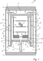
- FIG. 1 is a schematic, in part sectional, side view of a press apparatus according to an embodiment of the present invention.
- Figure 1 is a schematic, in part sectional, side view of a press apparatus 100 according to an embodiment of the present invention.
- the press apparatus 100 is arranged for treatment of at least one article by means of pressing, for example by means of hot pressing such as hot isostatic pressing (HIP).
- hot pressing such as hot isostatic pressing (HIP).
- the press apparatus 100 comprises a pressure vessel, which comprises a pressure cylinder 1 and a top end closure 8 and a bottom end closure 9, or more generally a first end closure and a second end closure, respectively. It is to be understood that the pressure vessel - which will be collectively referred to in the following by way of the reference numerals 1, 8 and 9 - may comprise additional parts, components or elements not illustrated in Figure 1 .
- the pressure vessel 1, 8, 9 is arranged to hold pressure medium therein during use of the press apparatus 100.
- the pressure vessel 1, 8, 9 comprises a furnace chamber 18.
- the furnace chamber 18 is arranged within the pressure vessel 1, 8, 9 so that pressure medium can enter and exit the furnace chamber 18.
- the furnace chamber 18 may comprise a furnace, or heater or heating elements, for heating of the pressure medium in the pressure vessel for example during a pressing phase of a treatment cycle.
- the furnace is schematically indicated in Figure 1 by the reference numerals 14. Parts of the furnace 14 are illustrated in Figure 1 as two identical elements indicated by the reference numerals 14. It is however to be understood that the furnace 14 could be provided in in principle any number of parts, and not only two parts as illustrated in Figure 1 , but fewer or more than two parts. In accordance with the embodiment of the present invention illustrated in Figure 1 , the furnace 14 is arranged at a lower part of the furnace chamber 18.
- furnace 14 in relation to, e.g., within, the furnace chamber 18
- the furnace 14 could be arranged at an upper part of the furnace chamber 18, such as, for example, in pressure medium guiding passage 32 shown in Figure 1 , which will be described further in the following.
- Any implementation of the furnace 14 with regards to arrangement thereof in relation to, e.g., within, the furnace chamber 18 may be used in any one of the embodiments of the present invention disclosed herein.
- the term "furnace” refers to the elements or means for providing heating
- the term “furnace chamber” refers to the area or region in which the furnace and possibly a load compartment and any article are located.
- the furnace chamber 18 may not occupy the whole inner space of the pressure vessel 1, 8, 9, but may leave an intermediate space 10 of the interior of the pressure vessel 1, 8, 9 around the furnace chamber 18.
- the intermediate space 10 forms a pressure medium guiding passage 10.
- the temperature in the intermediate space 10 may be lower than the temperature in the furnace chamber 18, but the intermediate space 10 and the furnace chamber 18 may be at equal, or substantially equal, pressure.
- the pressure vessel 1, 8, 9 includes a treatment space therein.
- the treatment space may for example be at least in part defined by the furnace chamber 18.
- the treatment space may be comprised or constituted by an interior of the furnace chamber 18.
- the treatment space is arranged to accommodate an article 5 (or possibly several articles).
- a load compartment 19 included in the furnace chamber 18 is arranged to accommodate the article 5.
- the treatment space may be comprised or constituted by an interior of the load compartment 19.
- the press apparatus 100 is configured to subject the article 5 to a treatment cycle, which treatment cycle includes a cooling phase.
- the outer surface of the outer walls of the pressure vessel 1, 8, 9 may be provided with channels, conduits or tubes, etc. (not shown in Figure 1 ), which channels, conduits or tubes for example may be arranged so as to be in connection with the outer surface of the outer wall of the pressure vessel 1, 8, 9, and which may be arranged to run parallel to an axial direction of the pressure vessel 1, 8, 9 or helically or spirally around the outer surface of the outer wall of the pressure vessel 1, 8, 9.
- a coolant for cooling of the walls of the pressure vessel 1, 8, 9 may be provided in the channels, conduits or tubes, whereby the walls of the pressure vessel 1, 8, 9 may be cooled in order to protect the walls from detrimental heat building up during operation of the pressure vessel 1, 8, 9.
- the coolant in the channels, conduits or tubes may for example comprise water, but another or other types of coolants are possible.
- An exemplifying flow of coolant in channels, conduits or tubes provided on the outer surface of the outer walls of the pressure vessel 1, 8, 9 is indicated in Figure 1 by the arrows on the outside of the pressure vessel 1, 8, 9.
- pre-stressing means On the outside surface of the outer walls of the pressure cylinder 1, and possibly on any channels, conduits and/or tubes, etc. for coolant as described in the foregoing, pre-stressing means may be provided.
- the pre-stressing means (not shown in Figure 1 ) may for example be provided in the form of wires (e.g., made of steel) wound in a plurality of turns so as to form one or more bands, and preferably in several layers, around the outside surface of the outer walls of the pressure cylinder 1 and possibly also any channels, conduits and/or tubes, etc. for coolant that may be provided thereon.
- the pre-stressing means may be arranged for exerting radial compressive forces on the pressure cylinder 1.
- the pressure vessel 1, 8, 9 may be arranged such that it can be opened and closed, such that any article within the pressure vessel 1, 8, 9 may be inserted or removed.
- An arrangement of the pressure vessel 1, 8, 9 such that it can be opened and closed may be realized in a number of different manners, as known in the art.
- one or both of the top end closure 8 and the bottom end closure 9 may be arranged so that it or they can be opened and closed.
- the press apparatus 100 comprises outer convection loop pressure medium guiding passages 10, 11, which are in fluid communication with the furnace chamber 18 and arranged to form an outer convection loop within the pressure vessel 1, 8, 9.
- the outer convection loop is arranged to guide the pressure medium after having exited the furnace chamber 18 in proximity to an inner surface 23 of wall(s) 22 of the pressure vessel 1, 8, 9 to a space 16 between the furnace chamber 18 and the bottom end closure 9.
- the wall(s) 22 of the pressure vessel 1, 8, 9 may be the outer wall(s) of the pressure vessel 1, 8, 9.
- the furnace chamber 18 is enclosed by a heat insulated casing - which will be collectively referred to in the following by way of the reference numerals 2, 4 and 7 - and is arranged so that pressure medium can enter and exit the furnace chamber 18.
- the heat insulated casing 2, 4, 7 comprises a heat insulating portion 7, a housing 2 which is partly enclosing the heat insulating portion 7, and a bottom insulating portion 4. Not all of the elements of the heat insulated casing 2, 4, 7 may be arranged so as to be heat insulated or heat insulating.
- the housing 2 may not necessarily be arranged so as to be heat insulated or heat insulating.
- the heat insulated casing 2, 4, 7 surrounding the furnace chamber 18 is likely to save energy during a heating phase of the treatment cycle to which the press apparatus 100 may be configured to subject the article 5 to.
- the heat insulated casing 2, 4, 7 may also facilitate or ensure that convection takes place in a more ordered manner. Because of the vertically elongated shape of the furnace chamber 18 in the illustrated embodiment of the present invention, the heat insulated casing 2, 4, 7 may prevent forming of temperature gradients, such as horizontal temperature gradients, which may be difficult to monitor and control.
- a part of the outer convection loop comprises a first outer convection loop pressure medium guiding passage 11, formed between portions of the housing 2 and the heat insulating portion 7, respectively, and which is arranged to guide the pressure medium after having exited the furnace chamber 18 to a space 17 between the top end closure 8 and the furnace chamber 18.
- another part of the outer convection loop comprises a second outer convection loop pressure medium guiding passage, which according to the illustrated embodiment is constituted by the pressure medium guiding passage 10.
- the second outer convection loop pressure medium guiding passage 10 is arranged to guide the pressure medium from the space 17 between the top end closure 8 and the furnace chamber 18 in proximity to the inner surface 23 of wall(s) 22 of the pressure vessel 1, 8, 9 to a space between the bottom insulating portion 4 and the bottom end closure 9.
- the mentioned space between the bottom insulating portion 4 and the bottom end closure 9 is constituting the above-mentioned space 16 between the furnace chamber 18 and the bottom end closure 9.
- the pressure medium used in the pressure vessel 1, 8, 9 or press apparatus 100 may for example comprise or be constituted by a liquid or gaseous medium which may have a relatively low chemical affinity in relation to the article(s) to be treated in the pressure vessel 1, 8, 9.
- the pressure medium may for example comprise a gas, for example an inert gas such as Argon gas.
- the pressure medium may exit the load compartment 19 at a top portion thereof and subsequently be guided in a pressure medium guiding passage 32 between the walls of the load compartment 19 and the heat insulating portion 7, after which the pressure medium may enter into the pressure medium guiding passage 11 by way of opening(s) 6 between the heat insulating portion 7 and the housing 2.
- the opening(s) 6 between the heat insulating portion 7 and the housing 2 may be at or approximately at the level of the bottom insulating portion 4, as illustrated in Figure 1 . It is however to be understood that the opening(s) 6 between the heat insulating portion 7 and the housing 2 may be at a different location than illustrated in Figure 1 .
- the opening(s) 6 between the heat insulating portion 7 and the housing 2 may possibly be provided with one or more valves or any other type of adjustable throttle or controllable pressure medium flow restriction means.
- the pressure medium that enters into the pressure medium guiding passage 11 by way of the opening(s) between the heat insulating portion 7 and the housing 2 is guided in the pressure medium guiding passage 11 towards the top end closure 8 where it may exit the pressure medium guiding passage 11 and the heat insulated casing 2, 4, 7 by way of an opening in the housing 2, e.g., a central opening in the housing 2, as illustrated in Figure 1 .
- a pressure medium guiding passage defined by the space 17 in part defined by the inner surface of the top end closure 8 and the pressure medium guiding passage 10 is arranged to guide the pressure medium having exited the opening in the housing 2 in proximity to the top end closure 8 and in proximity to an inner surface 23 of wall(s) 22 of the pressure vessel 1, 8, 9 (e.g., the wall(s) of the pressure cylinder 1, respectively, as illustrated in Figure 1 ) to the space 16 between the furnace chamber 18 and the bottom end closure 9.
- Figure 1 illustrates an exemplifying embodiment of the present invention, and that variations are possible, e.g., with respect to how the pressure medium is guided within the pressure vessel 1, 8, 9.
- a heat absorbing element as disclosed in WO 2018/171884 A1 , such as a heat absorbing body indicated by reference numeral 20 and as illustrated in the figures in WO 2018/171884 A1 .
- a heat exchanging element as disclosed in WO 2019/149379 A1 arranged in the top end closure 8, such as a heat exchanging element indicated by reference numeral 170 and as illustrated in the figures in WO 2019/149379 A1 .
- an outer convection loop may be formed by at least the pressure medium guiding passage 10 and the pressure medium guiding passage 11.
- the pressure medium is guided in proximity to the inner surface of the top end closure 8 and the inner surface 23 of wall(s) 22 of the pressure vessel 1, 8, 9, or pressure cylinder 1.
- the amount of thermal energy which may be transferred from the pressure medium during its passage in proximity to inner surfaces of the top end closure 8 and the inner surface 23 of walls 22 of the pressure vessel 1, 8, 9, or the pressure cylinder 1, may depend on at least one of the following: the speed of the pressure medium, the amount of pressure medium having (direct) contact with the inner surface of the top end closure 8 and the inner surface 23 of walls 22 of the pressure vessel 1, 8, 9, or the pressure cylinder 1, the relative temperature difference between the pressure medium and the inner surface of the top end closure 8 and the inner surface 23 of walls 22 of the pressure vessel 1, 8, 9, or the pressure cylinder 1, the thickness of the top end closure 8 and the thickness of walls 22 of the pressure vessel 1, 8, 9, or the pressure cylinder 1, and the temperature of any flow of coolant in channels, conduits or tubes provided on the outer surface of walls 22 of the pressure vessel 1, 8, 9, or the pressure cylinder 1 (indicated in Figure 1 by the arrows on the outside of the pressure cylinder 1).
- the pressure medium that is guided in the pressure medium guiding passage 10 back towards the furnace chamber 18 enters the space 16 between the furnace chamber 18 - or the bottom insulating portion 4 - and the bottom end closure 9.
- the furnace chamber 18 may be arranged so that pressure medium can enter the furnace chamber 18 from, and exit the furnace chamber 18 into, the space 16.
- the furnace chamber 18 may be provided with an opening in the bottom insulating portion 4 permitting pressure medium to flow into (or out of) the furnace chamber 18.
- a pressure medium guiding passage 12 e.g., comprising a conduit 12, is arranged so as to extend through the bottom insulating portion 4, with a lower (or first) opening of the pressure medium guiding passage or conduit 12 below the bottom insulating portion 4 (and possibly within the space 16, as per the illustrated embodiment) and an upper (or second) opening of the pressure medium guiding passage or conduit 12 at an upper surface of the bottom insulating portion 4 (and possibly aligned with an opening in the load compartment 19, as per the illustrated embodiment).
- the lower (or first) opening of the pressure medium guiding passage or conduit 12 may for example be provided with adjustable pressure medium flow restriction means such as one or more adjustable throttles or valves.
- the upper (or second) opening of the pressure medium guiding passage or conduit 12 could be at a distance from the upper surface of the bottom insulating portion 4.
- the pressure medium guiding passage 32 of the furnace chamber 18 and the pressure medium guiding passage formed between the load compartment 19 and the bottom insulating portion 4 are in fluid communication with the load compartment 19 so as to in part form an inner convection loop, wherein pressure medium in the inner convection loop is guided through the load compartment 19 and through the pressure medium guiding passage 32 of the furnace chamber 18 and the pressure medium guiding passage formed between the load compartment 19 and the bottom insulating portion 4 and back to the load compartment 19, or vice versa.
- the press apparatus 100 comprises a pressure medium circulation flow generator 15, which is configured to provide a circulation of pressure medium within the pressure vessel 1, 8, 9, wherein during the circulation of the pressure medium, the pressure medium passes through the furnace chamber 18.
- the pressure medium flow generator 15 is optional and may be omitted.
- the pressure medium circulation flow generator 15 comprises a fan 15 or the like for circulation of pressure medium within the furnace chamber 18.
- the pressure medium circulation flow generator 15 could comprise another or other types of pressure medium circulation flow generators than a fan, such as, for example, one or more ejectors.
- the pressure medium circulation flow generator 15 may for example be arranged at an opening in the load compartment 19 above the bottom insulating portion 4, which openings permits pressure medium flow into or out of the load compartment 19.
- the pressure medium circulation flow generator 15 may be controllable at least with respect to operating rate thereof.
- the operating rate of the pressure medium circulation flow generator 15 could for example comprise a number of revolutions per minute (rpm) of the pressure medium circulation flow generator 15, such as if it comprises or is constituted by one or more fans, etc., but another or other types of operating rates are contemplated, depending on the nature of the particular implementation of the pressure medium circulation flow generator 15.
- the pressure medium circulation flow generator 15 may be configured to selectively control the flow rate of pressure medium in the above-mentioned inner convection loop.
- the press apparatus 100 may comprise a pressure medium flow generator 13 arranged within the pressure vessel 1, 8, 9 and in fluid communication with the furnace chamber 18. At least during a cooling phase of the treatment cycle, the pressure medium flow generator 13 may be arranged to generate a transport of pressure medium from at least the space 16 between the furnace chamber 18 and the bottom end closure 4 into the furnace chamber 18 so as to cool the pressure medium in the treatment space.
- the pressure medium flow generator 13 comprises an ejector arrangement 13, which is only schematically illustrated in Figure 1 .
- pressure medium from the pressure medium guiding passage 10 which enters the space 16 may be drawn into the pressure medium flow generator 13 and subsequently be ejected from the flow generator 13 into the pressure medium guiding passage or conduit 12, which may then transport the pressure medium to the furnace chamber 18.
- the pressure medium flow generator 13 - for example comprising an ejector arrangement 13 - may comprise a single stage ejector, or a multi-stage ejector (e.g., a two-stage ejector).
- the pressure medium flow generator 13 or ejector arrangement 13 comprises one flow generator or ejector.
- the pressure medium flow generator 13 or ejector arrangement 13 comprises a plurality of flow generators or ejectors, which are arranged so that the output from at least one flow generator or ejector is input to another flow generator or ejector.
- the plurality of flow generators or ejectors may for example be arranged in series.
- the pressure medium flow generator 13 or ejector arrangement 13 may comprise a primary flow generator or ejector and a secondary flow generator or ejector, wherein the primary flow generator or ejector is arranged to draw pressure medium from the pressure medium guiding passage 10 which enters the space 16 into the primary flow generator or ejector.
- the output from the primary flow generator or ejector may be input into the secondary flow generator or ejector, and the output from the secondary flow generator or ejector may be ejected into the pressure medium guiding passage or conduit 12.
- the pressure medium flow generator 13 could for example comprise one or more fans, pumps, or the like, which may be arranged to cause a flow of pressure medium into the pressure medium guiding passage or conduit 12.
- the press apparatus 100 comprises at least one pressure medium guiding passage 21 arranged within the pressure vessel 1, 8, 9 such that pressure medium may pass from the furnace chamber 18 to the space 16 between the furnace chamber 18 and the bottom end closure 9, or vice versa, via only the at least one pressure medium guiding passage 21.
- Each of the at least one pressure medium guiding passage 21 is arranged such that a cross-section thereof in a plane perpendicular to a flow direction of the pressure medium through the pressure medium guiding passage 21 is formed as a gap having a width W, wherein each of the at least one pressure medium guiding passage 21 has a corresponding width, and wherein a sum of the width(s) is less than 4 mm.
- pressure medium guiding passage 21 there is a single such pressure medium guiding passage 21 arranged in the pressure vessel 1, 8, 9.
- pressure vessel 1, 8, 9 has a cylindrical geometry.
- the pressure medium guiding passage 21 is arranged such that a cross-section thereof in a plane perpendicular to a flow direction of the pressure medium through the pressure medium guiding passage 21 is formed as a gap having a width less than 4 mm. If there would be several such pressure medium guiding passages arranged in the pressure vessel 1, 8, 9, the total width of the corresponding cross-section widths (i.e. the sum of the corresponding cross-section widths) may be less than 4 mm.
- the dimensions of other parts of the press apparatus 100 may vary and may depend on the particular type of press apparatus.
- the pressure vessel 1, 8, 9 illustrated in Figure 1 has a cylindrical geometry. According to a non-limiting example, an inner diameter of the pressure cylinder 1 may be approximately 600 mm. A width of the pressure medium guiding passage 11 may be approximately 10 mm, and a width of the pressure medium guiding passage 10 may also be approximately 10 mm. An inner diameter of the heat insulating portion 7 may be approximately 500 mm. It is to be understood that these dimensions are exemplary and non-limiting, and may vary between different types of press apparatuses.
- the pressure medium guiding passage 21 is arranged such that pressure medium may pass from the furnace chamber 18 to the space 16 between the bottom insulating portion 4 and the bottom end closure 9, or vice versa, via only the pressure medium guiding passage 21. That the pressure medium may pass from the furnace chamber 18 to the space 16, or vice versa, via only the pressure medium guiding passage 21 means that the pressure medium does not need to pass through the outer convection loop in order to go from the furnace chamber 18 to the space 16, or vice versa, if the pressure medium goes via the pressure medium guiding passage 21.
- the bottom insulating portion 4 comprises a plate-shaped member, comprising a first outer surface 25, a second outer surface 26 opposite to the first outer surface, an edge surface 27 extending between the first outer surface 25 and the second outer surface 26, and a disc 20 attached to the second outer surface 26 (or possibly instead to the first outer surface 25).
- the disc 20 may be attached to the second outer surface 26 (or possibly instead to the first outer surface 25) for example by means of welding.
- the disc 20 is sized such that it extends over at least a part of a boundary of the second outer surface 26 (or possibly instead the first outer surface 25).
- the pressure medium guiding passage 21 is defined by a gap formed between an edge of the disc 20 and a surface of the housing 2.
- a disc 20 there may be provided a circular ring.
- the disc (or circular ring) and the plate-shaped member may not be separate components, but the disc (or circular ring) could be an integral part of the plate-shaped member.
- the disc 20 (or circular ring) may not be attached to the housing 2 or the heat insulating portion 7.
- the pressure medium guiding passage 21 illustrated in Figure 1 is exemplifying and that the pressure medium guiding passage could be realized in different ways.
- the pressure medium guiding passage 21 could be defined by a gap formed between the bottom insulating portion 4 and the housing 2.
- the bottom insulating portion 4 could comprise a plate-shaped member
- the pressure medium guiding passage 21 could be defined by a gap formed between an edge of the plate-shaped member and a surface of the housing 2.
- Other exemplifying realizations of the pressure medium guiding passage 21 are illustrated in and described with reference to Figures 2 and 3 .
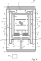
- FIG 2 is a schematic, in part sectional, side view of a press apparatus 100 according to an embodiment of the present invention.
- the press apparatus 100 illustrated in Figure 2 is similar to the press apparatus 100 illustrated in Figure 1 , and the same reference numerals in Figures 1 and 2 denote the same or similar components, having the same or similar function.
- the press apparatus 100 illustrated in Figure 2 has a different realization of the pressure medium guiding passage 21.
- the press apparatus 100 illustrated in Figure 2 comprises a circular ring 28, which is attached to a surface of the housing 2.
- the circular ring 28 is attached to the surface of the housing 2 (e.g., by means of screwing or welding) and sized such that the pressure medium guiding passage 21 is defined by a gap formed between the circular ring 28 and the bottom insulating portion 4. As illustrated in Figure 2 , the circular ring 28 may not be attached to the bottom insulating portion 4.
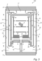
- Figure 3 is a schematic, in part sectional, side view of a press apparatus 100 according to an embodiment of the present invention.
- the press apparatus 100 illustrated in Figure 3 is similar to the press apparatus 100 illustrated in Figure 1 , and the same reference numerals in Figures 1 and 3 denote the same or similar components, having the same or similar function.
- the press apparatus 100 illustrated in Figure 3 has a different realization of the pressure medium guiding passage 21.
- the press apparatus 100 comprises a gasket 29, which is arranged intermediate a surface of the housing 2 and the bottom insulating portion 4.
- An outer gasket edge of the gasket 29 is connected to (possibly attached to) the surface of the housing 2, and an inner gasket edge of the gasket 29 is connected to (possibly attached to) the bottom insulating portion 4.
- the pressure medium guiding passage 21 is defined by a gap formed in the gasket 29.
- Figure 4 is a schematic, in part sectional, side view of a press apparatus 100 according to an embodiment of the present invention.
- the press apparatus 100 illustrated in Figure 4 is similar to the press apparatus 100 illustrated in Figure 1 , and the same reference numerals in Figures 1 and 4 denote the same or similar components, having the same or similar function.
- the press apparatus 100 illustrated in Figure 4 comprises a circular ring 33, which is arranged intermediate a surface of the housing 2 and the bottom insulating portion 4.
- the circular ring 33 is attached to the surface of the housing 2 and to the bottom insulating portion 4, respectively.
- the circular ring 33 may be attached to the surface of the housing 2 and to the bottom insulating portion 4 for example by means of screwing or welding.
- the pressure medium guiding passage 21 is arranged in the circular ring 33. It is to be understood that the pressure medium guiding passage 21 could be realized in other ways.
- the circular ring 33 could be attached to only one of the surface of the housing 2 and to the bottom insulating portion 4, and be sealed against the other of the surface of the housing 2 and to the bottom insulating portion 4.
- the press apparatus 100 illustrated in Figure 4 additionally comprises controllable pressure medium flow restrictions, schematically indicated at 34, which are arranged to selectively and controllably impede or obstruct a flow of pressure medium in the pressure medium guiding passage 21.
- the press apparatus 100 comprises a control unit 35, which is communicatively connected with the controllable pressure medium flow restrictions 34 for controlling operation thereof.
- the arrangement of the control unit 35 in relation to the pressure vessel 1, 8, 9 illustrated in Figure 4 is exemplifying and for illustrating principles of embodiments of the present invention.
- the controllable pressure medium flow restriction 34 may for example comprise one or more adjustable valves, such as, for example, one or more solenoid valves, pneumatic valves, and/or motor operated valves.
- a plurality of pressure medium guiding passages may be provided, which pressure medium guiding passages for example may be arranged in the circular ring 33.
- the plurality of pressure medium guiding passages may be distributed radially, in a regular or irregular manner, in the circular ring 33.
- Each pressure medium guiding passage might be provided with one or more corresponding controllable pressure medium flow restrictions.
- the control unit 35 is configured to control the controllable pressure medium flow restrictions 34 so as to impede or obstruct a flow of pressure medium in the pressure medium guiding passage 21 during a cooling phase of the treatment cycle (e.g., completely, or substantially completely, impede or obstruct flow of pressure medium in the pressure medium passage 21), and not impede or obstruct a flow of pressure medium in the pressure medium guiding passage 21 during another or other phases of the treatment cycle, including at least one of a heating phase and a vacuum phase.
- the press apparatus comprises a pressure vessel, arranged to hold pressure medium therein during use of the press apparatus.
- the pressure vessel comprises a top end closure and a bottom end closure.
- a furnace chamber is arranged within the pressure vessel so that pressure medium can enter and exit the furnace chamber, the furnace chamber at least in part defining a treatment space arranged to accommodate an article.
- the press apparatus comprises at least one outer convection loop pressure medium guiding passage in fluid communication with the furnace chamber and arranged to form an outer convection loop within the pressure vessel.
- the outer convection loop is arranged to guide the pressure medium after having exited the furnace chamber in proximity to an inner surface of wall(s) of the pressure vessel to a space between the furnace chamber and the bottom end closure.
- At least one pressure medium guiding passage is arranged within the pressure vessel such that pressure medium may pass from the furnace chamber to the space between the furnace chamber and the bottom end closure, or vice versa, via only the at least one pressure medium guiding passage.
Landscapes
- Engineering & Computer Science (AREA)
- Mechanical Engineering (AREA)
- Physics & Mathematics (AREA)
- Fluid Mechanics (AREA)
- Manufacturing & Machinery (AREA)
- Press Drives And Press Lines (AREA)
Claims (15)
- Pressvorrichtung (100) umfassend:einen Druckbehälter (1, 8, 9), der dafür angeordnet ist, Druckmittel darin während der Verwendung der Pressvorrichtung zu enthalten, wobei der Druckbehälter einen oberen Endverschluss (8) und einen unteren Endverschluss (9) umfasst;eine Ofenkammer (18), die so innerhalb des Druckbehälters angeordnet ist, dass Druckmittel in die Ofenkammer eintreten und aus ihr austreten kann, wobei die Ofenkammer wenigstens teilweise einen Behandlungsraum definiert, der dafür angeordnet ist, wenigstens einen Artikel (5) aufzunehmen, wobei die Pressvorrichtung dazu ausgebildet ist, den wenigstens einen Artikel einem Behandlungszyklus zu unterziehen, der eine Kühlphase beinhaltet;wenigstens einen Außenkonvektionsschleifen-Druckmittelführungsdurchgang (10, 11), der mit der Ofenkammer in Fluidverbindung steht und dafür angeordnet ist, eine Außenkonvektionsschleife innerhalb des Druckbehälters zu bilden, wobei die Außenkonvektionsschleife dafür angeordnet ist, das Druckmittel nach dem Austritt aus der Ofenkammer in der Nähe einer Innenfläche (23) von Wand (Wänden) (22) des Druckbehälters zu einem Raum (16) zwischen der Ofenkammer und dem unteren Endverschluss zu führen;einen Druckmittelströmungserzeuger (13), der innerhalb des Druckbehälters und in Fluidverbindung mit der Ofenkammer angeordnet ist, wobei wenigstens während einer Kühlphase des Behandlungszyklus der Druckmittelströmungserzeuger dafür angeordnet ist, eine Beförderung von Druckmittel von wenigstens dem Raum zwischen der Ofenkammer und dem unteren Endverschluss in die Ofenkammer zu erzeugen, so dass das Druckmittel in dem Behandlungsraum gekühlt wird;dadurch gekennzeichnet, dass wenigstens ein Druckmittelführungsdurchgang (21) so innerhalb des Druckbehälters angeordnet ist, dass das Druckmittel während einer Kühlphase nach dem Austritt aus der Ofenkammer über den wenigstens einen Druckmittelführungsdurchgang (21) von der Ofenkammer zu dem Raum (16) zwischen der Ofenkammer (18) und dem unteren Endverschluss (9) geführt werden kann, ohne die Außenkonvektionsschleife durchströmen zu müssen, bevor das Druckmittel in den Raum zwischen der Ofenkammer und dem unteren Endverschluss eintritt, wobei jeder von dem wenigstens einen Druckmittelführungsdurchgang so angeordnet ist, dass ein Querschnitt davon in einer Ebene senkrecht zu einer Strömungsrichtung des Druckmittels durch den Druckmittelführungsdurchgang (21) als ein Zwischenraum mit einer Breite (W) ausgebildet ist, wobei jeder von dem wenigstens einen Druckmittelführungsdurchgang eine entsprechende Breite aufweist, und wobei eine Summe der Breite(n) weniger als 4 mm beträgt.
- Pressvorrichtung nach Anspruch 1, wobei jeder von dem wenigstens einen Druckmittelführungsdurchgang so angeordnet ist, eine Summe der entsprechenden Querschnittbreite(n) in einem Bereich 0,1 mm bis 3,5 mm, optional in einem Bereich 0,1 mm bis 2,5 mm liegt.
- Pressvorrichtung nach einem der Ansprüche 1 bis 2, wobei der Druckmittelströmungserzeuger wenigstens in Bezug auf den Durchsatz von Druckmittel steuerbar ist, das von wenigstens dem Raum zwischen der Ofenkammer und dem unteren Endverschluss in die Ofenkammer befördert wird, wobei die Kühlrate des Druckmittels im Behandlungsbereich wenigstens teilweise durch den Durchsatz von Druckmittel geregelt wird, das von wenigstens dem Raum zwischen der Ofenkammer und dem unteren Endverschluss in die Ofenkammer befördert wird;
wobei jeder von dem wenigstens einen Druckmittelführungsdurchgang so angeordnet ist, dass eine Summe der entsprechenden Querschnittbreite(n) auf einem geschätzten Widerstand gegenüber einer Strömung von Druckmittel basiert, das in der Außenkonvektionsschleife nach dem Austritt aus der Ofenkammer bei Kühlraten geführt wird, die einen ausgewählten Kühlraten-Schwellenwert überschreiten, so dass die entsprechende(n) Querschnittbreite(n) bewirkt, dass ein Widerstand gegenüber einer Strömung von Druckmittel, das in dem Druckmittelführungsdurchgang unmittelbar nach dem Austritt aus der Ofenkammer zu dem Raum zwischen der Ofenkammer und dem unteren Endverschluss geführt wird, größer als der geschätzte Widerstand gegenüber der Strömung von Druckmittel wird, das in der Außenkonvektionsschleife nach dem Austritt aus der Ofenkammer geführt wird. - Pressvorrichtung nach einem der Ansprüche 1 bis 3, wobei jeder von dem wenigstens einen Druckmittelführungsdurchgang so angeordnet ist, dass ein Querschnitt davon in einer Ebene senkrecht zu einer Strömungsrichtung des Druckmittels durch den Druckmittelführungsdurchgang als ein Zwischenraum mit der Form von wenigstens einem Teil eines kreisförmigen Rings, einem Teil eines elliptischen Rings oder einem Kreis ausgebildet ist.
- Pressvorrichtung nach einem der Ansprüche 1 bis 4, wobei der Druckmittelströmungserzeuger wenigstens während der Kühlphase des Behandlungszyklus dafür angeordnet ist, eine Beförderung von Druckmittel von einem weiteren Raum in der Pressvorrichtung zu erzeugen, wobei während wenigstens eines Teils der Kühlphase die Temperatur des Druckmittels in dem anderen Raum niedriger als die Temperatur des Druckmittels im Behandlungsbereich ist, so dass durch Beförderung von Druckmittel während der Kühlphase von dem anderen Raum zum Behandlungsbereich die Temperatur des Druckmittels im Behandlungsbereich abnimmt, und/oder
wobei die Außenkonvektionsschleife dafür angeordnet ist, das Druckmittel nach dem Austritt aus der Ofenkammer zu einem Raum (17) zwischen dem oberen Endverschluss und der Ofenkammer zu führen und ferner das Druckmittel von dem Raum zwischen dem oberen Endverschluss und der Ofenkammer in der Nähe der Innenfläche von Wänden des Druckbehälters zu dem Raum zwischen der Ofenkammer und dem unteren Endverschluss zu führen. - Pressvorrichtung nach einem der Ansprüche 1 bis 5, umfassend:eine Mehrzahl von Außenkonvektionsschleifen-Druckmittelführungsdurchgängen (10, 11), die mit der Ofenkammer in Fluidverbindung stehen und so angeordnet sind, dass sie die Außenkonvektionsschleife bilden;wobei die Ofenkammer wenigstens teilweise von einem wärmeisolierten Mantel (2, 4, 7) umschlossen ist, der so angeordnet ist, dass Druckmittel in die Ofenkammer eintreten und aus ihr austreten kann, wobei der wärmeisolierte Mantel einen wärmeisolierenden Abschnitt (7), ein Gehäuse (2), das den wärmeisolierenden Abschnitt wenigstens teilweise umschließt, und einen unteren isolierenden Abschnitt (4) umfasst;wobei ein Teil der Außenkonvektionsschleife einen ersten Außenkonvektionsschleifen-Druckmittelführungsdurchgang (11) umfasst, der zwischen wenigstens Abschnitten des Gehäuses bzw. dem wärmeisolierenden Abschnitt ausgebildet ist und der dafür angeordnet ist, das Druckmedium nach dem Austritt aus der Ofenkammer zu einem Raum (17) zwischen dem oberen Endverschluss und der Ofenkammer zu führen, und wobei ein weiterer Teil der Außenkonvektionsschleife einen zweiten Außenkonvektionsschleifen-Druckmittelführungsdurchgang (10) umfasst, der dafür angeordnet ist, das Druckmittel von dem Raum zwischen dem oberen Endverschluss und der Ofenkammer in der Nähe der Innenfläche von Wänden des Druckbehälters zu einem Raum zwischen dem unteren isolierenden Abschnitt und dem unteren Endverschluss zu führen, wobei der Raum zwischen dem unteren isolierenden Abschnitt und dem unteren Endverschluss den Raum (16) zwischen der Ofenkammer und dem unteren Endverschluss bildet oder darin enthalten ist;wobei der wenigstens eine Druckmittelführungsdurchgang so angeordnet ist, dass während der Kühlphase das Druckmittel nach dem Austritt aus der Ofenkammer von der Ofenkammer über den wenigstens einen Druckmittelführungsdurchgang zu dem Raum zwischen dem unteren isolierenden Abschnitt und dem unteren Endverschluss geführt werden kann, ohne die Außenkonvektionsschleife durchströmen zu müssen, bevor das Druckmittel in den Raum zwischen dem unteren isolierenden Abschnitt und dem unteren Endverschluss eintritt.
- Pressvorrichtung nach Anspruch 6, wobei der wenigstens eine Druckmittelführungsdurchgang wenigstens teilweise von wenigstens einem Zwischenraum definiert ist, der zwischen dem unteren isolierenden Abschnitt und dem Gehäuse ausgebildet ist, und/oder wobei der untere isolierende Abschnitt ein plattenförmiges Glied umfasst, wobei der wenigstens eine Druckmittelführungsdurchgang wenigstens teilweise von wenigstens einem Zwischenraum definiert ist, der zwischen einer Kante des plattenförmigen Glieds und einer Fläche des Gehäuses ausgebildet ist.
- Pressvorrichtung nach einem der Ansprüche 6 bis 7, wobei der untere isolierende Abschnitt ein plattenförmiges Glied umfasst, das eine erste Außenfläche (25), eine zweite Außenfläche (26) gegenüber der ersten Außenfläche, eine Kantenfläche (27), die sich zwischen der ersten Außenfläche und der zweiten Außenfläche erstreckt, und eine Scheibe (20) oder einen kreisförmigen Ring, der an einer von der ersten Außenfläche und der zweiten Außenfläche angebracht ist, umfasst, wobei die Scheibe oder der kreisförmige Ring so bemessen ist, dass sich die Scheibe oder der kreisförmige Ring wenigstens über einen Teil einer Grenze der ersten Außenfläche oder der zweiten Außenfläche erstreckt, und wobei der wenigstens eine Druckmittelführungsdurchgang wenigstens teilweise von einem Zwischenraum definiert ist, der zwischen einer Kante der Scheibe oder des kreisförmigen Rings und einer Fläche des Gehäuses ausgebildet ist,oder wobei die Pressvorrichtung ferner einen kreisförmigen Ring (28) umfasst, der an einer Fläche des Gehäuses angebracht ist, wobei der kreisförmige Ring an der Fläche des Gehäuses angebracht ist und so bemessen ist, dass der wenigstens eine Druckmittelführungsdurchgang wenigstens teilweise von einem Zwischenraum definiert ist, der zwischen dem kreisförmigen Ring und dem unteren isolierenden Abschnitt ausgebildet ist,oder wobei die Pressvorrichtung ferner eine Dichtung (29) umfasst, die zwischen einer Fläche des Gehäuses und dem unteren isolierenden Abschnitt angeordnet ist, wobei eine Außendichtungskante mit der Fläche des Gehäuses verbunden ist und eine Innendichtungskante mit dem unteren isolierenden Abschnitt verbunden ist, wobei der wenigstens eine Druckmittelführungsdurchgang wenigstens teilweise von einem Zwischenraum definiert ist, der in der Dichtung ausgebildet ist.
- Pressvorrichtung nach einem der Ansprüche 1 bis 8, wobei der wenigstens eine Druckmittelführungsdurchgang gekrümmt ist.
- Pressvorrichtung (100) umfassend:einen Druckbehälter (1, 8, 9), der dafür angeordnet ist, Druckmittel darin während der Verwendung der Pressvorrichtung zu enthalten, wobei der Druckbehälter einen oberen Endverschluss (8) und einen unteren Endverschluss (9) umfasst;eine Ofenkammer (18), die so innerhalb des Druckbehälters angeordnet ist, dass Druckmittel in die Ofenkammer eintreten und aus ihr austreten kann, wobei die Ofenkammer wenigstens teilweise einen Behandlungsraum (19) definiert, der dafür angeordnet ist, wenigstens einen Artikel (5) aufzunehmen, wobei die Pressvorrichtung dazu ausgebildet ist, den wenigstens einen Artikel einem Behandlungszyklus zu unterziehen, der eine Kühlphase beinhaltet;wenigstens einen Außenkonvektionsschleifen-Druckmittelführungsdurchgang (10, 11), der mit der Ofenkammer in Fluidverbindung steht und dafür angeordnet ist, eine Außenkonvektionsschleife innerhalb des Druckbehälters zu bilden, wobei die Außenkonvektionsschleife dafür angeordnet ist, das Druckmittel nach dem Austritt aus der Ofenkammer in der Nähe einer Innenfläche (23) von Wand (Wänden) (22) des Druckbehälters zu einem Raum (16) zwischen der Ofenkammer und dem unteren Endverschluss zu führen;einen Druckmittelströmungserzeuger (13), der innerhalb des Druckbehälters und in Fluidverbindung mit der Ofenkammer angeordnet ist, wobei wenigstens während einer Kühlphase des Behandlungszyklus der Druckmittelströmungserzeuger dafür angeordnet ist, eine Beförderung von Druckmittel von wenigstens dem Raum zwischen der Ofenkammer und dem unteren Endverschluss in die Ofenkammer zu erzeugen, so dass das Druckmittel in dem Behandlungsraum gekühlt wird;wobei die Pressvorrichtung so angeordnet ist, dass die Ofenkammer wenigstens teilweise von einem wärmeisolierten Mantel (2, 4, 7) umschlossen ist, der so angeordnet ist, dass Druckmittel in die Ofenkammer eintreten und aus ihr austreten kann, wobei der wärmeisolierte Mantel einen wärmeisolierenden Abschnitt (7), ein Gehäuse (2), das den wärmeisolierenden Abschnitt wenigstens teilweise umschließt, und einen unteren isolierenden Abschnitt (4) umfasst, wobei ein wärmeabsorbierendes Element zwischen einem oberen Teil des wärmeisolierenden Abschnitts und einer Öffnung im Gehäuse und/oder so angeordnet ist, dass ein Wärmeaustauschelement im oberen Endverschluss angeordnet ist; dadurch gekennzeichnet, dass wenigstens ein Druckmittelführungsdurchgang (21) so innerhalb des Druckbehälters angeordnet ist, dass das Druckmittel während einer Kühlphase nach dem Austritt aus der Ofenkammer über den wenigstens einen Druckmittelführungsdurchgang von der Ofenkammer zu dem Raum (16) zwischen der Ofenkammer (18) und dem unteren Endverschluss geführt werden kann, ohne die Außenkonvektionsschleife durchströmen zu müssen, bevor das Druckmittel in den Raum zwischen der Ofenkammer und dem unteren Endverschluss eintritt;eine oder mehrere steuerbare Druckmittelströmungsbegrenzungen (34), die so angeordnet sind, dass sie eine Druckmittelströmung in dem wenigstens einen Druckmittelführungsdurchgang selektiv und steuerbar hemmen oder blockieren; undeine Steuereinheit (35), die mit der einen oder den mehreren steuerbaren Druckmittelströmungsbegrenzungen zur Steuerung des Betriebs derselben kommunikativ verbunden ist, wobei die Steuereinheit dazu ausgebildet ist, die eine oder die mehreren steuerbaren Druckmittelströmungsbegrenzungen so zu steuern, dass sie eine Druckmittelströmung in dem wenigstens einen Druckmittelführungsdurchgang während einer Kühlphase des Behandlungszyklus hemmen oder blockieren und eine Druckmittelströmung in dem wenigstens einen Druckmittelführungsdurchgang während einer weiteren oder anderer Phasen des Behandlungszyklus, einschließlich wenigstens einer von einer Heizphase, einer Haltephase, einer Pumpphase und einer Vakuumphase oder einer beliebigen Kombination davon, nicht hemmen oder blockieren.
- Pressvorrichtung nach Anspruch 10, ferner umfassend:einen kreisförmigen Ring (33), der zwischen einer Fläche des Gehäuses und dem unteren isolierenden Abschnitt angeordnet ist;wobei die Pressvorrichtung eine Mehrzahl von Druckmittelführungsdurchgängen umfasst, die innerhalb des Druckbehälters so angeordnet sind, dass das Druckmittel während der Kühlphase nach dem Austritt aus der Ofenkammer über die Mehrzahl von Druckmittelführungsdurchgängen von der Ofenkammer zu dem Raum zwischen der Ofenkammer und dem unteren Endverschluss geführt werden kann, ohne die Außenkonvektionsschleife durchströmen zu müssen, bevor das Druckmittel in den Raum zwischen der Ofenkammer und dem unteren Endverschluss eintritt, wobei die Mehrzahl von Druckmittelführungsdurchgängen in dem kreisförmigen Ring (33) radial angeordnet und verteilt ist;wobei die Pressvorrichtung eine Mehrzahl von steuerbaren Druckmittelströmungsbegrenzungen (34) umfasst, die so angeordnet sind, dass sie eine Druckmittelströmung in der Mehrzahl von Druckmitteldurchgängen selektiv und steuerbar hemmen oder blockieren, wobei jeder der Mehrzahl von Druckmitteldurchgängen mit einer oder mehreren entsprechenden Druckmittelströmungsbegrenzungen der Mehrzahl von steuerbaren Druckmittelströmungsbegrenzungen versehen ist;wobei die Steuereinheit (35) dazu ausgebildet ist, die Mehrzahl von steuerbaren Druckmittelströmungsbegrenzungen so zu steuern, dass sie eine Druckmittelströmung in der Mehrzahl von Druckmittelführungsdurchgängen während der Kühlphase des Behandlungszyklus hemmen oder blockieren und eine Druckmittelströmung in der Mehrzahl von Druckmittelführungsdurchgängen während einer weiteren oder anderer Phasen des Behandlungszyklus, einschließlich wenigstens einer von der Heizphase, der Haltephase, der Pumpphase und der Vakuumphase oder einer beliebigen Kombination davon, nicht hemmen oder blockieren.
- Verfahren in einer Pressvorrichtung, die Pressvorrichtung umfassend einen Druckbehälter (1, 8, 9), der dafür angeordnet ist, Druckmittel darin während der Verwendung der Pressvorrichtung zu enthalten, wobei der Druckbehälter einen oberen Endverschluss (8) und einen unteren Endverschluss (9) umfasst, eine Ofenkammer (18), die so innerhalb des Druckbehälters angeordnet ist, dass Druckmittel in die Ofenkammer eintreten und aus ihr austreten kann, wobei die Ofenkammer wenigstens teilweise einen Behandlungsraum (19) definiert, der dafür angeordnet ist, wenigstens einen Artikel (5) aufzunehmen, wobei die Pressvorrichtung dazu ausgebildet ist, den wenigstens einen Artikel einem Behandlungszyklus zu unterziehen, der eine Kühlphase beinhaltet, die Pressvorrichtung ferner umfassend wenigstens einen Außenkonvektionsschleifen-Druckmittelführungsdurchgang (10, 11), der mit der Ofenkammer in Fluidverbindung steht und dafür angeordnet ist, eine Außenkonvektionsschleife innerhalb des Druckbehälters zu bilden, wobei die Außenkonvektionsschleife dafür angeordnet ist, das Druckmittel nach dem Austritt aus der Ofenkammer in der Nähe einer Innenfläche (23) von Wand (Wänden) (22) des Druckbehälters zu einem Raum (16) zwischen der Ofenkammer und dem unteren Endverschluss zu führen, die Pressvorrichtung ferner umfassend einen Druckmittelströmungserzeuger (13), der innerhalb des Druckbehälters und in Fluidverbindung mit der Ofenkammer angeordnet ist, wobei wenigstens während einer Kühlphase des Behandlungszyklus der Druckmittelströmungserzeuger dafür angeordnet ist, eine Beförderung von Druckmittel von wenigstens dem Raum zwischen der Ofenkammer und dem unteren Endverschluss in die Ofenkammer zu erzeugen, so dass das Druckmittel in dem Behandlungsraum gekühlt wird, wobei die Pressvorrichtung ferner wenigstens einen Druckmittelführungsdurchgang (21) umfasst, der innerhalb des Druckbehälters so angeordnet ist, dass das Druckmittel während einer Kühlphase nach dem Austritt aus der Ofenkammer über den wenigstens einen Druckmittelführungsdurchgang von der Ofenkammer zu dem Raum zwischen der Ofenkammer und dem unteren Endverschluss geführt werden kann, ohne die Außenkonvektionsschleife durchströmen zu müssen, bevor das Druckmittel in den Raum zwischen der Ofenkammer und dem unteren Endverschluss eintritt, wobei die Pressvorrichtung ferner eine oder mehrere steuerbare Druckmittelströmungsbegrenzungen (34) umfasst, die so angeordnet sind, dass sie eine Druckmittelströmung in dem wenigstens einen Druckmittelführungsdurchgang selektiv und steuerbar hemmen oder blockieren, das Verfahren umfassend:Steuern der einen oder der mehreren steuerbaren Druckmittelströmungsbegrenzungen, so dass sie eine Druckmittelströmung in dem wenigstens einen Druckmittelführungsdurchgang während einer Kühlphase des Behandlungszyklus hemmen oder blockieren und eine Druckmittelströmung in dem wenigstens einen Druckmittelführungsdurchgang während einer weiteren oder anderer Phasen des Behandlungszyklus, einschließlich wenigstens einer von einer Heizphase, einer Haltephase, einer Pumpphase und einer Vakuumphase oder einer beliebigen Kombination davon, nicht hemmen oder blockieren;wobei die Pressvorrichtung so angeordnet ist, dass:die Ofenkammer wenigstens teilweise von einem wärmeisolierten Mantel (2, 4, 7) umschlossen ist, der so angeordnet ist, dass Druckmittel in die Ofenkammer eintreten und aus ihr austreten kann, wobei der wärmeisolierte Mantel einen wärmeisolierenden Abschnitt (7), ein Gehäuse (2), das den wärmeisolierenden Abschnitt wenigstens teilweise umschließt, und einen unteren isolierenden Abschnitt (4) umfasst, wobei ein wärmeabsorbierendes Element zwischen einem oberen Teil des wärmeisolierenden Abschnitts und einer Öffnung im Gehäuse angeordnet ist;und/oder so, dass:
ein Wärmeaustauschelement im oberen Endverschluss angeordnet ist. - Verfahren nach Anspruch 12, wobei die Pressvorrichtung ferner einen kreisförmigen Ring (33) umfasst, der zwischen einer Fläche des Gehäuses und dem unteren isolierenden Abschnitt angeordnet ist, wobei die Pressvorrichtung eine Mehrzahl von Druckmittelführungsdurchgängen umfasst, die innerhalb des Druckbehälters so angeordnet sind, dass das Druckmittel während der Kühlphase nach dem Austritt aus der Ofenkammer über die Mehrzahl von Druckmittelführungsdurchgängen von der Ofenkammer zu dem Raum zwischen der Ofenkammer und dem unteren Endverschluss geführt werden kann, ohne die Außenkonvektionsschleife durchströmen zu müssen, bevor das Druckmittel in den Raum zwischen der Ofenkammer und dem unteren Endverschluss eintritt, wobei die Mehrzahl von Druckmittelführungsdurchgängen in dem kreisförmigen Ring radial angeordnet und verteilt ist, und wobei die Pressvorrichtung eine Mehrzahl von steuerbaren Druckmittelströmungsbegrenzungen umfasst, die so angeordnet sind, dass sie eine Druckmittelströmung in der Mehrzahl von Druckmitteldurchgängen selektiv und steuerbar hemmen oder blockieren, wobei jeder der Mehrzahl von Druckmitteldurchgängen mit einer oder mehreren entsprechenden Druckmittelströmungsbegrenzungen der Mehrzahl von steuerbaren Druckmittelströmungsbegrenzungen versehen ist, das Verfahren umfassend:
Steuern der Mehrzahl von steuerbaren Druckmittelströmungsbegrenzungen, so dass sie eine Druckmittelströmung in der Mehrzahl von Druckmittelführungsdurchgängen während der Kühlphase des Behandlungszyklus hemmen oder blockieren und eine Druckmittelströmung in der Mehrzahl von Druckmittelführungsdurchgängen während einer weiteren oder anderer Phasen des Behandlungszyklus, einschließlich wenigstens einer von der Heizphase, der Haltephase, der Pumpphase und der Vakuumphase oder einer beliebigen Kombination davon, nicht hemmen oder blockieren. - Computerprogramm, das Anweisungen umfasst, die bei Ausführung durch einen oder mehrere Prozessoren, die in einer Steuereinheit enthalten sind, die Steuereinheit dazu veranlassen, ein Verfahren nach Anspruch 12 oder 13 durchzuführen.
- Computerlesbares Medium wird bereitgestellt, das ein darauf geladenes Computerprogramm aufweist, wobei das Computerprogramm Anweisungen umfasst, die bei Ausführung durch einen oder mehrere Prozessoren, die in einer Steuereinheit enthalten sind, die Steuereinheit dazu veranlassen, ein Verfahren nach Anspruch 12 oder 13 durchzuführen.
Applications Claiming Priority (1)
| Application Number | Priority Date | Filing Date | Title |
|---|---|---|---|
| PCT/EP2020/074438 WO2022048739A1 (en) | 2020-09-02 | 2020-09-02 | A press apparatus |
Publications (3)
| Publication Number | Publication Date |
|---|---|
| EP4208334A1 EP4208334A1 (de) | 2023-07-12 |
| EP4208334C0 EP4208334C0 (de) | 2024-09-25 |
| EP4208334B1 true EP4208334B1 (de) | 2024-09-25 |
Family
ID=72381064
Family Applications (1)
| Application Number | Title | Priority Date | Filing Date |
|---|---|---|---|
| EP20767752.7A Active EP4208334B1 (de) | 2020-09-02 | 2020-09-02 | Pressvorrichtung |
Country Status (7)
| Country | Link |
|---|---|
| US (1) | US20230241853A1 (de) |
| EP (1) | EP4208334B1 (de) |
| JP (1) | JP7521113B2 (de) |
| KR (1) | KR102877855B1 (de) |
| CN (1) | CN115867433A (de) |
| ES (1) | ES3006023T3 (de) |
| WO (1) | WO2022048739A1 (de) |
Family Cites Families (9)
| Publication number | Priority date | Publication date | Assignee | Title |
|---|---|---|---|---|
| JPH0726787B2 (ja) * | 1988-03-09 | 1995-03-29 | 株式会社神戸製鋼所 | 熱間静水圧加圧装置及び同装置の冷却運転方法 |
| JPH0510680A (ja) * | 1991-06-20 | 1993-01-19 | Kobe Steel Ltd | 熱間等方圧加圧装置 |
| JPH09133470A (ja) * | 1995-11-09 | 1997-05-20 | Kobe Steel Ltd | 熱間等方圧加圧装置及び当該装置の冷却方法 |
| SE521206C2 (sv) | 2002-02-20 | 2003-10-14 | Flow Holdings Sagl | Förfarande för kylning av en ugnskammare för varmisostatisk pressning och en anordning härför |
| US9358747B2 (en) | 2007-12-14 | 2016-06-07 | Avure Technologies Ab | Hot isostatic pressing arrangement |
| WO2012092961A1 (en) | 2011-01-03 | 2012-07-12 | Avure Technologies Ab | Pressing arrangement |
| RU2553173C2 (ru) * | 2011-01-03 | 2015-06-10 | Авуре Текнолоджиз Аб | Усовершенствованный внешний охлаждающий контур |
| ES2954993T3 (es) * | 2017-03-23 | 2023-11-28 | Quintus Technologies Ab | Disposición de prensado |
| EP3749512A1 (de) | 2018-02-05 | 2020-12-16 | Quintus Technologies AB | Pressanordnung und verfahren zum kühlen eines artikels in besagter anordnung |
-
2020
- 2020-09-02 US US18/023,972 patent/US20230241853A1/en active Pending
- 2020-09-02 JP JP2023513113A patent/JP7521113B2/ja active Active
- 2020-09-02 WO PCT/EP2020/074438 patent/WO2022048739A1/en not_active Ceased
- 2020-09-02 CN CN202080103450.7A patent/CN115867433A/zh active Pending
- 2020-09-02 EP EP20767752.7A patent/EP4208334B1/de active Active
- 2020-09-02 KR KR1020237010727A patent/KR102877855B1/ko active Active
- 2020-09-02 ES ES20767752T patent/ES3006023T3/es active Active
Also Published As
| Publication number | Publication date |
|---|---|
| CN115867433A (zh) | 2023-03-28 |
| EP4208334C0 (de) | 2024-09-25 |
| EP4208334A1 (de) | 2023-07-12 |
| KR20230060516A (ko) | 2023-05-04 |
| KR102877855B1 (ko) | 2025-10-28 |
| JP7521113B2 (ja) | 2024-07-23 |
| WO2022048739A1 (en) | 2022-03-10 |
| JP2023539585A (ja) | 2023-09-15 |
| ES3006023T3 (en) | 2025-03-17 |
| US20230241853A1 (en) | 2023-08-03 |
Similar Documents
| Publication | Publication Date | Title |
|---|---|---|
| CN111683806B (zh) | 压制设备和冷却所述设备中的制品的方法 | |
| EP4025416B1 (de) | Verfahren zur steuerung der kühlrate in einer heisspressanordnung, steuermodul und pressanordnung an sich | |
| EP4208334B1 (de) | Pressvorrichtung | |
| US12479024B2 (en) | Method in a pressing arrangement | |
| US12496794B2 (en) | Method in a pressing arrangement | |
| CN110678319B (zh) | 压制设备 | |
| JP7238248B2 (ja) | 熱処理炉 | |
| EP3749511B1 (de) | Verfahren zur verarbeitung von gegenständen und verfahren zur hochdruckbehandlung von gegenständen | |
| RU2798409C1 (ru) | Способ регулирования скорости охлаждения в оборудовании горячего прессования, модуль управления и оборудование прессования |
Legal Events
| Date | Code | Title | Description |
|---|---|---|---|
| STAA | Information on the status of an ep patent application or granted ep patent |
Free format text: STATUS: UNKNOWN |
|
| STAA | Information on the status of an ep patent application or granted ep patent |
Free format text: STATUS: THE INTERNATIONAL PUBLICATION HAS BEEN MADE |
|
| PUAI | Public reference made under article 153(3) epc to a published international application that has entered the european phase |
Free format text: ORIGINAL CODE: 0009012 |
|
| STAA | Information on the status of an ep patent application or granted ep patent |
Free format text: STATUS: REQUEST FOR EXAMINATION WAS MADE |
|
| 17P | Request for examination filed |
Effective date: 20230314 |
|
| AK | Designated contracting states |
Kind code of ref document: A1 Designated state(s): AL AT BE BG CH CY CZ DE DK EE ES FI FR GB GR HR HU IE IS IT LI LT LU LV MC MK MT NL NO PL PT RO RS SE SI SK SM TR |
|
| DAV | Request for validation of the european patent (deleted) | ||
| DAX | Request for extension of the european patent (deleted) | ||
| GRAP | Despatch of communication of intention to grant a patent |
Free format text: ORIGINAL CODE: EPIDOSNIGR1 |
|
| STAA | Information on the status of an ep patent application or granted ep patent |
Free format text: STATUS: GRANT OF PATENT IS INTENDED |
|
| INTG | Intention to grant announced |
Effective date: 20240422 |
|
| GRAS | Grant fee paid |
Free format text: ORIGINAL CODE: EPIDOSNIGR3 |
|
| GRAA | (expected) grant |
Free format text: ORIGINAL CODE: 0009210 |
|
| STAA | Information on the status of an ep patent application or granted ep patent |
Free format text: STATUS: THE PATENT HAS BEEN GRANTED |
|
| AK | Designated contracting states |
Kind code of ref document: B1 Designated state(s): AL AT BE BG CH CY CZ DE DK EE ES FI FR GB GR HR HU IE IS IT LI LT LU LV MC MK MT NL NO PL PT RO RS SE SI SK SM TR |
|
| REG | Reference to a national code |
Ref country code: GB Ref legal event code: FG4D |
|
| REG | Reference to a national code |
Ref country code: CH Ref legal event code: EP |
|
| REG | Reference to a national code |
Ref country code: DE Ref legal event code: R096 Ref document number: 602020038354 Country of ref document: DE |
|
| REG | Reference to a national code |
Ref country code: IE Ref legal event code: FG4D |
|
| U01 | Request for unitary effect filed |
Effective date: 20240930 |
|
| U07 | Unitary effect registered |
Designated state(s): AT BE BG DE DK EE FI FR IT LT LU LV MT NL PT RO SE SI Effective date: 20241024 |
|
| PG25 | Lapsed in a contracting state [announced via postgrant information from national office to epo] |
Ref country code: NO Free format text: LAPSE BECAUSE OF FAILURE TO SUBMIT A TRANSLATION OF THE DESCRIPTION OR TO PAY THE FEE WITHIN THE PRESCRIBED TIME-LIMIT Effective date: 20241225 |
|
| PG25 | Lapsed in a contracting state [announced via postgrant information from national office to epo] |
Ref country code: GR Free format text: LAPSE BECAUSE OF FAILURE TO SUBMIT A TRANSLATION OF THE DESCRIPTION OR TO PAY THE FEE WITHIN THE PRESCRIBED TIME-LIMIT Effective date: 20241226 |
|
| PG25 | Lapsed in a contracting state [announced via postgrant information from national office to epo] |
Ref country code: RS Free format text: LAPSE BECAUSE OF FAILURE TO SUBMIT A TRANSLATION OF THE DESCRIPTION OR TO PAY THE FEE WITHIN THE PRESCRIBED TIME-LIMIT Effective date: 20241225 |
|
| PG25 | Lapsed in a contracting state [announced via postgrant information from national office to epo] |
Ref country code: RS Free format text: LAPSE BECAUSE OF FAILURE TO SUBMIT A TRANSLATION OF THE DESCRIPTION OR TO PAY THE FEE WITHIN THE PRESCRIBED TIME-LIMIT Effective date: 20241225 Ref country code: NO Free format text: LAPSE BECAUSE OF FAILURE TO SUBMIT A TRANSLATION OF THE DESCRIPTION OR TO PAY THE FEE WITHIN THE PRESCRIBED TIME-LIMIT Effective date: 20241225 Ref country code: GR Free format text: LAPSE BECAUSE OF FAILURE TO SUBMIT A TRANSLATION OF THE DESCRIPTION OR TO PAY THE FEE WITHIN THE PRESCRIBED TIME-LIMIT Effective date: 20241226 |
|
| REG | Reference to a national code |
Ref country code: ES Ref legal event code: FG2A Ref document number: 3006023 Country of ref document: ES Kind code of ref document: T3 Effective date: 20250317 |
|
| PG25 | Lapsed in a contracting state [announced via postgrant information from national office to epo] |
Ref country code: IS Free format text: LAPSE BECAUSE OF FAILURE TO SUBMIT A TRANSLATION OF THE DESCRIPTION OR TO PAY THE FEE WITHIN THE PRESCRIBED TIME-LIMIT Effective date: 20250125 |
|
| PG25 | Lapsed in a contracting state [announced via postgrant information from national office to epo] |
Ref country code: SM Free format text: LAPSE BECAUSE OF FAILURE TO SUBMIT A TRANSLATION OF THE DESCRIPTION OR TO PAY THE FEE WITHIN THE PRESCRIBED TIME-LIMIT Effective date: 20240925 |
|
| PG25 | Lapsed in a contracting state [announced via postgrant information from national office to epo] |
Ref country code: CZ Free format text: LAPSE BECAUSE OF FAILURE TO SUBMIT A TRANSLATION OF THE DESCRIPTION OR TO PAY THE FEE WITHIN THE PRESCRIBED TIME-LIMIT Effective date: 20240925 Ref country code: PL Free format text: LAPSE BECAUSE OF FAILURE TO SUBMIT A TRANSLATION OF THE DESCRIPTION OR TO PAY THE FEE WITHIN THE PRESCRIBED TIME-LIMIT Effective date: 20240925 |
|
| PG25 | Lapsed in a contracting state [announced via postgrant information from national office to epo] |
Ref country code: SK Free format text: LAPSE BECAUSE OF FAILURE TO SUBMIT A TRANSLATION OF THE DESCRIPTION OR TO PAY THE FEE WITHIN THE PRESCRIBED TIME-LIMIT Effective date: 20240925 |
|
| PLBE | No opposition filed within time limit |
Free format text: ORIGINAL CODE: 0009261 |
|
| STAA | Information on the status of an ep patent application or granted ep patent |
Free format text: STATUS: NO OPPOSITION FILED WITHIN TIME LIMIT |
|
| 26N | No opposition filed |
Effective date: 20250626 |
|
| U20 | Renewal fee for the european patent with unitary effect paid |
Year of fee payment: 6 Effective date: 20250815 |
|
| PGFP | Annual fee paid to national office [announced via postgrant information from national office to epo] |
Ref country code: GB Payment date: 20250813 Year of fee payment: 6 |