EP4207800A2 - Loudspeaker assembly with a waveguide - Google Patents
Loudspeaker assembly with a waveguide Download PDFInfo
- Publication number
- EP4207800A2 EP4207800A2 EP22217155.5A EP22217155A EP4207800A2 EP 4207800 A2 EP4207800 A2 EP 4207800A2 EP 22217155 A EP22217155 A EP 22217155A EP 4207800 A2 EP4207800 A2 EP 4207800A2
- Authority
- EP
- European Patent Office
- Prior art keywords
- waveguide
- loudspeaker
- loudspeaker assembly
- grille
- diaphragm
- Prior art date
- Legal status (The legal status is an assumption and is not a legal conclusion. Google has not performed a legal analysis and makes no representation as to the accuracy of the status listed.)
- Pending
Links
- 239000000203 mixture Substances 0.000 description 27
- 230000000712 assembly Effects 0.000 description 9
- 238000000429 assembly Methods 0.000 description 9
- 230000005540 biological transmission Effects 0.000 description 8
- 230000004044 response Effects 0.000 description 6
- 230000007246 mechanism Effects 0.000 description 4
- 230000006872 improvement Effects 0.000 description 3
- 238000003339 best practice Methods 0.000 description 2
- 238000004806 packaging method and process Methods 0.000 description 2
- 230000008901 benefit Effects 0.000 description 1
- 230000008878 coupling Effects 0.000 description 1
- 238000010168 coupling process Methods 0.000 description 1
- 238000005859 coupling reaction Methods 0.000 description 1
- 210000005069 ears Anatomy 0.000 description 1
- 239000002184 metal Substances 0.000 description 1
- 230000000116 mitigating effect Effects 0.000 description 1
- 230000004048 modification Effects 0.000 description 1
- 238000012986 modification Methods 0.000 description 1
- 230000005855 radiation Effects 0.000 description 1
Images


Classifications
-
- H—ELECTRICITY
- H04—ELECTRIC COMMUNICATION TECHNIQUE
- H04R—LOUDSPEAKERS, MICROPHONES, GRAMOPHONE PICK-UPS OR LIKE ACOUSTIC ELECTROMECHANICAL TRANSDUCERS; DEAF-AID SETS; PUBLIC ADDRESS SYSTEMS
- H04R9/00—Transducers of moving-coil, moving-strip, or moving-wire type
- H04R9/06—Loudspeakers
-
- H—ELECTRICITY
- H04—ELECTRIC COMMUNICATION TECHNIQUE
- H04R—LOUDSPEAKERS, MICROPHONES, GRAMOPHONE PICK-UPS OR LIKE ACOUSTIC ELECTROMECHANICAL TRANSDUCERS; DEAF-AID SETS; PUBLIC ADDRESS SYSTEMS
- H04R1/00—Details of transducers, loudspeakers or microphones
- H04R1/20—Arrangements for obtaining desired frequency or directional characteristics
- H04R1/32—Arrangements for obtaining desired frequency or directional characteristics for obtaining desired directional characteristic only
- H04R1/34—Arrangements for obtaining desired frequency or directional characteristics for obtaining desired directional characteristic only by using a single transducer with sound reflecting, diffracting, directing or guiding means
- H04R1/345—Arrangements for obtaining desired frequency or directional characteristics for obtaining desired directional characteristic only by using a single transducer with sound reflecting, diffracting, directing or guiding means for loudspeakers
-
- H—ELECTRICITY
- H04—ELECTRIC COMMUNICATION TECHNIQUE
- H04R—LOUDSPEAKERS, MICROPHONES, GRAMOPHONE PICK-UPS OR LIKE ACOUSTIC ELECTROMECHANICAL TRANSDUCERS; DEAF-AID SETS; PUBLIC ADDRESS SYSTEMS
- H04R1/00—Details of transducers, loudspeakers or microphones
- H04R1/02—Casings; Cabinets ; Supports therefor; Mountings therein
- H04R1/023—Screens for loudspeakers
-
- H—ELECTRICITY
- H04—ELECTRIC COMMUNICATION TECHNIQUE
- H04R—LOUDSPEAKERS, MICROPHONES, GRAMOPHONE PICK-UPS OR LIKE ACOUSTIC ELECTROMECHANICAL TRANSDUCERS; DEAF-AID SETS; PUBLIC ADDRESS SYSTEMS
- H04R7/00—Diaphragms for electromechanical transducers; Cones
- H04R7/02—Diaphragms for electromechanical transducers; Cones characterised by the construction
- H04R7/12—Non-planar diaphragms or cones
-
- H—ELECTRICITY
- H04—ELECTRIC COMMUNICATION TECHNIQUE
- H04R—LOUDSPEAKERS, MICROPHONES, GRAMOPHONE PICK-UPS OR LIKE ACOUSTIC ELECTROMECHANICAL TRANSDUCERS; DEAF-AID SETS; PUBLIC ADDRESS SYSTEMS
- H04R9/00—Transducers of moving-coil, moving-strip, or moving-wire type
- H04R9/02—Details
-
- H—ELECTRICITY
- H04—ELECTRIC COMMUNICATION TECHNIQUE
- H04R—LOUDSPEAKERS, MICROPHONES, GRAMOPHONE PICK-UPS OR LIKE ACOUSTIC ELECTROMECHANICAL TRANSDUCERS; DEAF-AID SETS; PUBLIC ADDRESS SYSTEMS
- H04R1/00—Details of transducers, loudspeakers or microphones
- H04R1/02—Casings; Cabinets ; Supports therefor; Mountings therein
- H04R1/025—Arrangements for fixing loudspeaker transducers, e.g. in a box, furniture
-
- H—ELECTRICITY
- H04—ELECTRIC COMMUNICATION TECHNIQUE
- H04R—LOUDSPEAKERS, MICROPHONES, GRAMOPHONE PICK-UPS OR LIKE ACOUSTIC ELECTROMECHANICAL TRANSDUCERS; DEAF-AID SETS; PUBLIC ADDRESS SYSTEMS
- H04R1/00—Details of transducers, loudspeakers or microphones
- H04R1/20—Arrangements for obtaining desired frequency or directional characteristics
- H04R1/22—Arrangements for obtaining desired frequency or directional characteristics for obtaining desired frequency characteristic only
- H04R1/28—Transducer mountings or enclosures modified by provision of mechanical or acoustic impedances, e.g. resonator, damping means
- H04R1/2807—Enclosures comprising vibrating or resonating arrangements
- H04R1/2853—Enclosures comprising vibrating or resonating arrangements using an acoustic labyrinth or a transmission line
- H04R1/2857—Enclosures comprising vibrating or resonating arrangements using an acoustic labyrinth or a transmission line for loudspeaker transducers
-
- H—ELECTRICITY
- H04—ELECTRIC COMMUNICATION TECHNIQUE
- H04R—LOUDSPEAKERS, MICROPHONES, GRAMOPHONE PICK-UPS OR LIKE ACOUSTIC ELECTROMECHANICAL TRANSDUCERS; DEAF-AID SETS; PUBLIC ADDRESS SYSTEMS
- H04R1/00—Details of transducers, loudspeakers or microphones
- H04R1/20—Arrangements for obtaining desired frequency or directional characteristics
- H04R1/22—Arrangements for obtaining desired frequency or directional characteristics for obtaining desired frequency characteristic only
- H04R1/30—Combinations of transducers with horns, e.g. with mechanical matching means, i.e. front-loaded horns
-
- H—ELECTRICITY
- H04—ELECTRIC COMMUNICATION TECHNIQUE
- H04R—LOUDSPEAKERS, MICROPHONES, GRAMOPHONE PICK-UPS OR LIKE ACOUSTIC ELECTROMECHANICAL TRANSDUCERS; DEAF-AID SETS; PUBLIC ADDRESS SYSTEMS
- H04R2400/00—Loudspeakers
- H04R2400/11—Aspects regarding the frame of loudspeaker transducers
-
- H—ELECTRICITY
- H04—ELECTRIC COMMUNICATION TECHNIQUE
- H04R—LOUDSPEAKERS, MICROPHONES, GRAMOPHONE PICK-UPS OR LIKE ACOUSTIC ELECTROMECHANICAL TRANSDUCERS; DEAF-AID SETS; PUBLIC ADDRESS SYSTEMS
- H04R2499/00—Aspects covered by H04R or H04S not otherwise provided for in their subgroups
- H04R2499/10—General applications
- H04R2499/13—Acoustic transducers and sound field adaptation in vehicles
Abstract

Description
- This application claims the benefit of
U.S. provisional application Serial No. 63/296,040 filed January 3, 2022 - Aspects disclosed herein generally relate to a loudspeaker assembly including at least a waveguide or horn. Specifically, one or more of the disclosed embodiments generally to a loudspeaker assembly including the waveguide or horn that may be used in connection with automotive audio applications. These aspects and other will be discussed in more detail below.
- Loudspeaker assemblies are known to include a waveguide. The waveguide may be used to shape an overall directivity of audio transmitted from a loudspeaker. For example, the waveguide may be used to either narrow or widen the sound field of audio transmitted from the loudspeaker in different frequencies which may affect both soundstage and tonality. In automotive applications, it is desirable to implement loudspeaker assemblies such that the waveguide guides the audio toward one or more vehicle occupants.
- In at least one embodiment, a loudspeaker assembly is provided. The loudspeaker assembly includes a loudspeaker and a waveguide. The loudspeaker includes a diaphragm to transmit an audio output. The waveguide being asymmetrical and at least partially surrounding the diaphragm. The waveguide being configured to control a directivity of the audio output.
- In at least one embodiment, a loudspeaker assembly is provided. The loudspeaker assembly includes a loudspeaker and a waveguide. The loudspeaker is positioned on a mirror sail, a body pillar, or a door trim of a vehicle. The loudspeaker includes a diaphragm to transmit an audio output in the vehicle. The waveguide at least partially surrounds the diaphragm and is configured to control a directivity of the audio output in the vehicle.
- In at least one embodiment, a loudspeaker assembly is provided. The loudspeaker assembly includes a loudspeaker and a waveguide. The loudspeaker includes a diaphragm to transmit an audio output in a vehicle. The waveguide at least partially surrounds the diaphragm and is configured to transmit the audio output in both a vertical and horizontal direction in the vehicle.
- The embodiments of the present disclosure are pointed out with particularity in the appended claims. However, other features of the various embodiments will become more apparent and will be best understood by referring to the following detailed description in conjunction with the accompanying drawings in which:
-
FIGURE 1 depicts one example of a loudspeaker assembly positioned in a vehicle in accordance with an embodiment; -
FIGURE 2 depicts a front view of the loudspeaker assembly ofFIGURE 1 in accordance with an embodiment; -
FIGURE 3 depicts a first cross-sectional view of the loudspeaker assembly ofFIGURE 2 in accordance with an embodiment; -
FIGURE 4 depicts a second cross-sectional view of the loudspeaker assembly ofFIGURE 2 in accordance with an embodiment; -
FIGURE 5 depicts a third cross-sectional view of the loudspeaker assembly ofFIGURE 2 in accordance with an embodiment; -
FIGURE 6 depicts an exploded view of the loudspeaker assembly in accordance with an embodiment; -
FIGURE 7 illustrates various directivity orientations for an audio output from the loudspeaker assembly in accordance with an embodiment; -
FIGURE 8 depicts a front view of another loudspeaker assembly in accordance with an embodiment; -
FIGURE 9 depicts various on-axis waveforms as provided for different tweeter speaker grilles and for the loudspeaker grille illustrated in connection withFIGURE 8 in accordance with one embodiment; -
FIGURE 10 depicts various off-axis waveforms for a first angle as provided for different tweeter speaker grilles and for the loudspeaker grille illustrated in connection withFIGURE 8 in accordance with one embodiment; -
FIGURE 11 depicts various off-axis waveforms for a second angle as provided for different tweeter speaker grilles and for the loudspeaker grille illustrated in connection withFIGURE 8 in accordance with one embodiment; -
FIGURE 12 depicts various off-axis waveforms for a third angle as provided for different tweeter speaker grilles and for the loudspeaker grille illustrated in connection withFIGURE 8 in accordance with one embodiment; -
FIGURE 13 depicts various off-axis waveforms for a fourth angle as provided for different tweeter speaker grilles and for the loudspeaker grille illustrated in connection withFIGURE 8 in accordance with one embodiment; and -
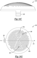
FIGUREs 14A - 14G depict various views of the loudspeaker grille in accordance with one embodiment. - As required, detailed embodiments of the present invention are disclosed herein; however, it is to be understood that the disclosed embodiments are merely exemplary of the invention that may be embodied in various and alternative forms. The figures are not necessarily to scale; some features may be exaggerated or minimized to show details of particular components. Therefore, specific structural and functional details disclosed herein are not to be interpreted as limiting, but merely as a representative basis for teaching one skilled in the art to variously employ the present invention.
- Aspects disclosed herein generally provide a loudspeaker assembly having a waveguide that serves as an interface to improve directivity and efficiency for a loudspeaker. In one example, the loudspeaker may be a tweeter that transmits audio in a range of 1.5 kHz to 40 kHz. It is recognized herein that the loudspeaker may also be a woofer or a mid-range loudspeaker. The waveguide may be asymmetric and flared on a front side thereof. The waveguide may be lensed at a rear side. Such a surface geometry of the waveguide may, among other things, control a radiation or sound field of the audio output of the loudspeaker and optimize the transmission and receipt of the sound at occupant positions in a vehicle. The waveguide may provide, for example, a coverage angle of the transmitted audio for 60 degrees both in horizontal and vertical directions.
- Aspects disclosed provide a loudspeaker assembly that was developed in response to, among other things, a problem of having to design and re-design horn/waveguides that are tailored to specific customer requirements for performance and packaging. The disclosed horn/waveguide includes a core structure having a creased flare and a continuous blend in its surface geometry. The stability in performance realized with the core surface geometry of the waveguide creates a horn/waveguide that can accommodate a variety of exterior (trim) shapes without affecting overall performance. For this reason, the core can be re-used across many vehicles and only modifications to the exterior shape may need to be made. The geometry of the loudspeaker's core (or diaphragm) may remain the same regardless of specific customer requirements. The disclosed loudspeaker assembly generally incorporates at least a diaphragm and a waveguide including a creased flare, a continuous blend, and an asymmetrical convex surface that morphs or evolves into a concave surface (or acoustic lens). The core or diaphragm may generally remain the same and its surrounding surface area that forms the waveguide may be easily fine-tuned to accommodate slight adjustments that allow the diaphragm to fit any outer trim shape necessary to accommodate specific customer requirements without affecting performance.
- An outer trim, (that may nor may not necessarily be modular or separate from the diaphragm), can be modified without affecting the overall performance of the core. Due to the surface geometry of the core, the shape of the trim portion may be changed, based on vehicle packaging requirements, without affecting performance. The waveguide of the loudspeaker assembly may utilize a creased flare on a front surface thereof and a continuous blend for remaining surfaces of the waveguide. The waveguide may include 4 cross sectional areas or sections in which three of such sections may be convex. The rear cross sections of the waveguide start as a convex portion and blend into a concave surface.
- One object provided by the waveguide and its specific geometry may control the directivity of the loudspeaker provided to occupants in the vehicle and may remove sound from unnecessary locations in the vehicle. The disclosed loudspeaker assembly may (i) improve direction of the sound waves toward the location of listeners (e.g., focus sound at the location of the users and remove the sound from being projected or transmitted toward unnecessary locations (i.e., improves directivity)), (ii) create a similar listening experience over the coverage area, (iii) create a similar listening experience (e.g., frequency response) across height/head locations, (iv) increase output of, for example, a high-frequency loudspeaker, and (v) achieve above listed audio performance improvement in a small form factor. Prior implementations of loudspeaker assemblies may not provide a horn or waveguide or do not have as much directivity control of direct sound within the automotive space. It is recognized that the at least a portion of the acoustic function provided the loudspeaker assembly may be dictated or controlled by the surface geometry of the waveguide.
-
FIGURE 1 depicts one example of aloudspeaker assembly 100 positioned in avehicle 102 in accordance with an embodiment. In general, theloudspeaker assembly 100 includes aloudspeaker 101 and is configured to transmit an audio output to one or more vehicle occupants in thevehicle 102. As shown, theassembly 100 may be positioned in amirror sail 104 of thevehicle 102. However, it is recognized that theassembly 100 may by positioned anywhere along an A-pillar 106 of thevehicle 102. In general, theloudspeaker assembly 100 may be configured to transmit the audio output to one or more vehicle occupants positioned in at least a first row of thevehicle 102. While not shown, theloudspeaker assembly 100 may be positioned anywhere along B, C and/or D pillars of thevehicle 102 to transmit the audio output to at least vehicle occupants positioned in a second row and/or third row of thevehicle 102. It is further recognized that theloudspeaker assembly 100 may be positioned on any one or more of the A, B, C, or D pillars (body pillar) of thevehicle 102. It is also recognized that theassembly 100 may be positioned in any door trim that is located in thevehicle 102. - Similarly, while
FIGURE 1 illustrates that theloudspeaker assembly 100 may be positioned on a left side of the vehicle 102 (e.g., driver side of the vehicle 102), it is recognized that there may be anadditional loudspeaker assembly 100 positioned opposite to theloudspeaker assembly 100 on a right side of thevehicle 102 and on a mirror sail 104 (orbody pillar 106 such as an A-pillar) of thevehicle 102. In generally, theloudspeaker assembly 100 may be positioned as a pair of assemblies for any given row of seating in thevehicle 102. Likewise, theassembly 100 may be positioned on right and left door trims for one or more rows of seating in thevehicle 102 - The
loudspeaker assembly 100 includes adiaphragm 110 and a waveguide (or horn) 112. Thediaphragm 110 along with at least a voice coil (not shown) form theloudspeaker 101 of theassembly 100. It is recognized that theloudspeaker 101 may be a tweeter that transmits audio in a range of 1.5 kHz to 40 kHz. It is recognized herein that the loudspeaker may also be a woofer or a mid-range loudspeaker. - The
waveguide 112 generally surrounds thediaphragm 110 and serves to control the directivity of the audio output toward vehicle occupants while simultaneously preventing the audio output from being directed towards afront windshield 120 of thevehicle 102 and/or adoor windshield 122. Thewaveguide 112 includes a first (or rear)portion 130 and a second (or front)portion 132. Thefirst portion 130 may generally be defined as a "continuous blend 130" and thesecond portion 132 may be defined as a "creasedflare 132" hereafter. Aspects related to thecontinuous blend 130 and thecreased flare 132 will be discussed in more detail in connection withFIGUREs 2-6 . Thecontinuous blend 130 and thecreased flare 132 cooperate with one another to provide a horn that increases the efficiency of the frequency of the audio output from theloudspeaker 101. For example, thecontinuous blend 130 and thecreased flare 132 may increase the overall power output of the audio transmitted by theloudspeaker 101. -
FIGURE 2 depicts a front view of theloudspeaker assembly 100 ofFIGURE 1 in accordance with an embodiment. As shown, thediaphragm 110 is generally recessed within thewaveguide 112. Thediaphragm 110 is radially surrounded by thecontinuous blend 130 and thecreased flare 132. Anouter lip 144 surrounds thecontinuous blend 130 and thecreased flare 132. Thecontinuous blend 130 may be formed or shaped in a cone-like manner and thecreased flare 132 includes afirst crease 150 and asecond crease 152 for separating thecontinuous blend 130 from the creasedflare 132. It is recognized that any number of creases may be provided on the creasedflare 132. Similarly, the creases may be positioned on thecontinuous blend 130 instead of the on the creasedflare 132. The number of creases positioned on thecontinuous blend 130 or thecreased flare 132 may vary based on the desired criteria of a particular implementation. An overall profile of the waveguide is asymmetrical in reference toaxis 143 that extends horizontally alongdiaphragm 110 assuming theloudspeaker assembly 100 is positioned in thevehicle 102 as shown inFIGURE 1 . -
FIGURE 3 depicts a first cross-sectional view of theloudspeaker assembly 100 ofFIGURE 2 in accordance with an embodiment. Thewaveguide 112 includes athroat 160 that surrounds thediaphragm 110. Thethroat 160 receives thediaphragm 110 and forms aconvex surface portion 162 on both thecontinuous blend 130 and thecreased flare 132. Theconvex surface portion 162 is positioned directly adjacent to thediaphragm 110. Thewaveguide 112 includes amouth 166 positioned directly above thethroat 160. Theconvex surface portion 162 is positioned between themouth 166 and thediaphragm 110. - The
mouth 166 forms aconcave surface portion 170 that is positioned between theouter lip 144 and theconvex surface portion 162 on at least a portion of thecontinuous blend 130 As shown inFIGURE 3 , the creasedflare 132 does not include theconcave surface portion 170 and theconcave surface portion 170 is positioned only on thecontinuous blend 130 The creasedflare 132 extends to a length from an outer perimeter of thediaphragm 110 that is greater than a length in which thecontinuous blend 130 extends from the outer perimeter of thediaphragm 110. Referring toFIGUREs 3 and4 , thewaveguide 112 includes a plurality of receivingmechanisms 172a - 172n (or "172") to enable theassembly 100 to be coupled to thevehicle 102. This aspect will be discussed in more detail below. -
FIGURE 5 depicts a third cross-sectional view of theloudspeaker assembly 100 ofFIGURE 2 in accordance with an embodiment. As generally shown inFIGURE 5 , thecontinuous blend 130 and thecreased flare 132 includes theconvex surface portion 162. Theloudspeaker assembly 100 includes aconnecter 180 for electrically coupling theassembly 100 to thevehicle 102. Theouter lip 144 includes afirst side 182 and asecond side 184. Thefirst side 182 of theouter lip 144 extends to a length from thediaphragm 110 that is greater than a length of thesecond side 184 to the diaphragm 110 (e.g., see length difference betweenfirst side 182 and thesecond side 184 relative to vertical axis 190). It is recognized that the overall length between thediaphragm 110 and thefirst side 182 and thesecond side 184 may also be similar to one another. -
FIGURE 6 depicts an exploded view of theloudspeaker assembly 100 in accordance with an embodiment. The assembly includes thediaphragm 110, thewaveguide 112, aloudspeaker grille 200, and a plurality offastening mechanisms 202a - 202n. Theloudspeaker grille 200 covers thediaphragm 110 and thewaveguide 112. In one example, theloudspeaker grille 200 may be positioned on theouter lip 144. The receivingmechanisms 172 receive the fastening mechanisms 202 to couple theloudspeaker assembly 100 to thevehicle 102. -
FIGURE 7 illustrates various directivity orientations for an audio output from theloudspeaker assembly 100 in accordance with an embodiment. Thewaveguide 112 as set forth above, may provide, for example, a coverage angle of the transmitted audio in a range of 35 to 80 degrees both in horizontal and vertical directions.FIGURE 6 illustrates that the audio is directed toward an interior of thevehicle 102 towards vehicle occupant(s). In particular, theloudspeaker assembly 100 transmits the audio output to left and right ears for a driver and a passenger in thevehicle 102 and that theloudspeaker assembly 100 is generally effective in mitigating the transmission of the audio output to areas of thevehicle 102 where occupants are not positioned. As shown, theassembly 100 may transmit audio near passenger ("NP") (i.e., passenger closest to assembly 100) and to an opposite passenger ("OP"). -
FIGURE 8 depicts a front view of anotherloudspeaker assembly 300 in accordance with one embodiment. Theassembly 300 is generally similar to theassembly 100 as illustrated in connection withFIGURE 2 . However, theassembly 300 includes agrille 302 that is positioned directly over thediaphragm 110. In the embodiment shown inFIGURE 8 , thegrille 302 covers thediaphragm 110 while thewaveguide 112 is uncovered (e.g., portions of thecontinuous blend 130 and thecreased flare 132 are uncovered). It is recognized that other embodiments, thegrille 302 may cover thediaphragm 110, thecontinuous blend 130 and thecreased flare 132 in similar manner illustrated in connection withFIGURE 6 . Thegrille 302 generally includes afirst section 304 and asecond section 306. As shown, thegrille 302 generally defines a plurality ofopenings 310 to enable audio to pass therethrough. - The
openings 310 may be formed in one or more of thefirst section 304 and thesecond section 306. Thegrille 302 as illustrated inFIGURE 8 shows thatopenings 310 are formed in both thefirst section 304 and thesecond section 306. In one example, a logo may be formed by the plurality ofopenings 310 positioned in thefirst section 304. For example, thefirst section 304 illustrates that the plurality ofopenings 310 forms a logo associated with JBL ™ audio related products. It is recognized thatgrille 302 may not require the need for a logo or other identifier in other embodiments. - In general, the
grille 302 in addition to the characteristics noted above in connection with thewaveguide 112 provide a unique and highly desirable acoustic responds in thevehicle 102. For example, thewaveguide 112 in collaboration with thegrille 302 may optimize sound where vehicle occupants are located in thevehicle 102. In thevehicle 102, listeners (or occupants) may be positioned, for example, 20 and 80 degrees off-axis from theloudspeaker assemblies loudspeaker assemblies loudspeaker 101. - The
waveguide 112 and thegrille 302 serve to improve the off-axis performance of theloudspeaker 101 in thevehicle 102. In general, it may be desirable to improve audio performance for theloudspeaker 101 by taking into account where the occupants are located in thevehicle 102. Such an improvement may be realized by improving the off-axis transmission of the audio into thevehicle 102. Thewaveguide 112 and thegrille 302 provides a better on-axis response compared to prior automotive loudspeaker assemblies that either have a grille or does not have a grille. In general, loudspeaker assemblies that are not equipped with a grille are often considered to be ideal. In addition, while thewaveguide 112 improves off-axis performance, it has been found that thegrille 302 has provided additional improvement with off-axis performance when added to thewaveguide 112. Individually, each of thewaveguide 112 and thegrille 302 improve the off-axis performance when compared to typical automotive applications. - With the disclosed
grille 302, theopenings 310 are positioned over the entire surface area of thefirst section 302 and thesecond section 304. In general, theopenings 302 may be orientated diagonally (or non-perpendicularly) with respect to theaxis 143 that extends horizontally and centrally across a front face of thegrille 302. The overall width (or predetermined width) of theopenings 310 formed in thefirst section 302 may be different than the width of theopenings 310 formed in thesecond section 304. In one example, an overall thickness of thegrille 310 and the correspondingopenings 310 may be 1.5 mm (e.g., assuming that thegrille 310 is made of plastic) which is considered minimal but still meets automotive standards/best practices. In the event the grille 301 is formed of metal, the overall thickness of thegrille 310 may be 0.8mm. The differing widths between theopenings 310 in thefirst section 304 and the openings 301 in thesecond section 306, the thickness of thegrille 302 being formed at a predetermined thickness, and an overall distance of thegrille 310 relative to theloudspeaker 101 may create a unique acoustic response that has similar/improved on-axis performance and improved off-axis performance when compared to grilles that are not equipped with a grille or to conventional automotive grilles. As recognized, given that thewaveguide 112 and thegrille 302 may be implemented on both the driver side and passenger side of the vehicle, thewaveguide 112 and thegrille 302 is mirrored when positioned on either side of the vehicle. For example, thewaveguide 112 and thegrille 302 as shown in connection withFIGURE 8 correspond to such features being implemented on a driver side (e.g., left side of the vehicle). When thewaveguide 112 and thegrille 302 are positioned on the passenger side (e.g., right side of the vehicle), such awaveguide 112 andgrille 302 are mirrored with respect to thewaveguide 112 and thegrille 302 as illustrated inFIGURE 8 . - The
grille 302 is generally recessed within thewaveguide 112. Thegrille 302 may also be surrounded by thecontinuous blend 130 and thecreased flare 132. Theouter lip 144 surrounds thecontinuous blend 130 and thecreased flare 132. As noted above, thecontinuous blend 130 may be formed or shaped in a cone-like manner and thecreased flare 132 includes thefirst crease 150 and thesecond crease 152 for separating thecontinuous blend 130 from the creasedflare 132. As also noted above, it is recognized that any number of creases may be provided on the creasedflare 132. Similarly, the creases may be positioned on thecontinuous blend 130 instead of the on the creasedflare 132. The number of creases positioned on thecontinuous blend 130 or thecreased flare 132 may vary based on the desired criteria of a particular implementation. An overall profile of thewaveguide 112 is asymmetrical in reference to theaxis 143 that extends horizontally alongdiaphragm 110 assuming theloudspeaker assembly 100 is positioned in thevehicle 102 as shown inFIGURE 1 . -
FIGURE 9 depicts aplot 400 illustrating various on-axis waveforms as provided for different tweeter speaker grilles and for theloudspeaker grille 302 illustrated in connection withFIGURE 8 in accordance with one embodiment. In general, thewaveforms 400 includes areference waveform 402, afirst waveform 404 and asecond waveform 408. Thereference waveform 402 corresponds to a loudspeaker assembly that includes thewaveguide 112 and does not include a grille. In general, the audio as output and shown via thereference waveform 402 may not be acceptable for automotive standards but may be considered an ideal case for other applications. Thefirst waveform 404 generally corresponds to an audio output by loudspeaker assemblies that are equipped with thewaveguide 112 and a conventional grille. Thesecond waveform 408 corresponds to an audio output provided by theloudspeaker assembly 300 including thegrille 302 and thewaveguide 112 as set forth above. An on-axis audio performance (or transmission) in connection with thesecond waveform 408 is better than the performance of the loudspeaker exhibited by thefirst waveform 404. For example, grilles typically degrade sound quality in general. One objective may be to minimize the impact of the grille so that sound quality can be as high as possible. Grille thickness and open area (e.g., % opening, hole pattern, and where the openings exist) may play advantageous roles in minimizing the impact of the grille. - The disclosed
grille 302 includes openings that are positioned in areas thereof along with thewaveguide 112 to improve the sound based on the desired response. The sound is allowed to pass on and off-axis in a desired manner by optimizing the open area (ratio) with the pattern. -
FIGURE 10 depicts aplot 500 illustrating various off-axis waveforms as provided for different tweeter speaker grilles and for theloudspeaker grille 302 illustrated in connection withFIGURE 8 in accordance with one embodiment. The waveforms correspond to a 20 degree off-axis audio transmission. In general, thewaveforms 500 includes areference waveform 502, afirst waveform 504 and asecond waveform 508. Thereference waveform 502 corresponds to a loudspeaker assembly that includes thewaveguide 112 and does not include a grille. As noted above, the audio as output and shown via thereference waveform 502 may not be acceptable for automotive standards but may be considered an ideal case for other applications. Thefirst waveform 504 generally corresponds to an audio output by a loudspeaker assembly that is equipped with thewaveguide 112 but with a conventional grille. Thesecond waveform 508 corresponds to an audio output provided by theloudspeaker assembly 300 including thewaveguide 112 and thegrille 302 as set forth above. As shown, the 20 degree off-axis performance in connection with thesecond waveform 508 is better than the performance of the conventional loudspeaker exhibited by thefirst waveform 504. -
FIGURE 11 depicts aplot 600 illustrating various on-axis waveforms as provided for different tweeter speaker grilles and for theloudspeaker grille 302 illustrated in connection withFIGURE 8 in accordance with one embodiment. The waveforms correspond to a 40 degree off-axis audio transmission. In general, thewaveforms 600 includes areference waveform 602,first waveform 604, and asecond waveform 608. Thereference waveform 602 corresponds to a loudspeaker assembly that includes thewaveguide 112 and does not include a grille. As noted above, the audio as output and shown via thereference waveform 602 may not be acceptable for automotive standards but may be considered an ideal case for other applications. Thefirst waveform 604 generally corresponds to an audio output by a loudspeaker assembly that includes thewaveguide 112 and a conventional grille. Thesecond waveform 608 corresponds to an audio output provided by theloudspeaker assembly 300 including thegrille 302 and thewaveguide 112 as set forth above. As shown, the 40 degree off-axis performance in connection with thesecond waveform 608 is better than the performance of thefirst waveform 604. -
FIGURE 12 depicts aplot 700 illustrating various on-axis waveforms as provided for different tweeter speaker grilles and for theloudspeaker grille 302 illustrated in connection withFIGURE 8 in accordance with one embodiment. The waveforms correspond to a 60 degree off-axis audio transmission. In general, thewaveforms 700 includes areference waveform 702, afirst waveform 704, and asecond waveform 708. Thereference waveform 702 corresponds to a loudspeaker assembly that includes thewaveguide 112 and does not include a grille. As noted above, the audio as output and shown via thereference waveform 702 may not be acceptable for automotive standards but may be considered an ideal case for other applications. Thefirst waveform 704 generally corresponds to an audio output by a loudspeaker that is equipped with thewaveguide 112 and with a conventional grille. Thesecond waveform 708 corresponds to an audio output provided by theloudspeaker assembly 300 including thewaveguide 112 and thegrille 302 as set forth above. As shown, the 60 degree off-axis performance in connection with thesecond waveform 708 is better than the performance of the conventional loudspeaker exhibited by thefirst waveform 704. -
FIGURE 13 depicts aplot 800 illustrating various on-axis waveforms as provided for different tweeter speaker grilles and for theloudspeaker grille 302 illustrated in connection withFIGURE 8 in accordance with one embodiment. The waveforms correspond to an 80 degree off-axis audio transmission. In general, thewaveforms 800 includes areference waveform 802, afirst waveform 804, and asecond waveform 808. Thereference waveform 802 corresponds to a loudspeaker assembly that includes thewaveguide 112 and does not include a grille. As noted above, the audio as output and shown via thereference waveform 802 may not be acceptable for automotive standards but may be considered an ideal case for other applications. Thefirst waveform 804 generally corresponds to an audio output by a loudspeaker assembly including thewaveguide 112 and a conventional grille. Thesecond waveform 808 corresponds to an audio output provided by theloudspeaker assembly 300 including thewaveguide 112 and thegrille 302 as set forth above. As shown, the 80 degree off-axis performance in connection with thesecond waveform 808 is better than the performance of the conventional loudspeaker exhibited by thefirst waveform 804. -
FIGUREs 14A - 14G depict various view of the loudspeaker grille in accordance with one embodiment. For example,FIGURE 14A depicts a front view of theloudspeaker grille 302 in accordance with one embodiment. As noted above, thegrille 302 includes thefirst section 304 and thesecond section 306. In one example, thefirst section 304 includesfirst openings 310a and thesecond section 306 includessecond opening 310b that differ from thefirst openings 310a. - A
center axis 312 extends centrally through thegrille 302. Each of thefirst openings 310a and thesecond openings 310b may be orientated diagonally (or non-perpendicularly) with respect to theaxis 312 that extends horizontally and centrally across a front face of thegrille 302. The overall width (or predetermined width) of thefirst openings 310a formed in thefirst section 302 may be different than the width of theopenings 310 formed in thesecond section 304. In one example, an overall thickness of thegrille 302 and the correspondingfirst openings 310a and the second openings 301b may be 15 mm which may be considered minimal but still meets automotive standards/best practices. The differing widths between thefirst openings 310a in thefirst section 304 and thesecond openings 310b in thesecond section 306, the thickness of thegrille 302 being formed at a predetermined thickness, and an overall distance of thegrille 310 relative to the loudspeaker 101 (seeFIGURE 6 for loudspeaker 101) may create a unique acoustic response that has similar/improved on-axis performance and improved off-axis performance when compared to grilles that are not equipped with a grille or to conventional automotive grilles. Thegrille 302 may optionally include atab 320 positioned on thereon, for example, on a side section thereof. Thetab 320 may also be a key to ensure proper orientation when being coupled to thewaveguide 112. As noted above, thetab 320 may be optional in terms of whether it is present with theassembly 300. -
FIGUREs 14B - 14G illustrate thegrille 302 in various orientations. According to an embodiment, an overall ornamental appearance of theloudspeaker grille 302 is illustrated inFIGUREs 8 and14A - 14G . - While exemplary embodiments are described above, it is not intended that these embodiments describe all possible forms of the invention. Rather, the words used in the specification are words of description rather than limitation, and it is understood that various changes may be made without departing from the spirit and scope of the invention. Additionally, the features of various implementing embodiments may be combined to form further embodiments of the invention.
Claims (15)
- A loudspeaker assembly comprising:a loudspeaker including a diaphragm to transmit an audio output; anda waveguide being asymmetrical and including a first portion and a second portion, the waveguide at least partially surrounding the diaphragm and configured to control a directivity of the audio output.
- The loudspeaker assembly of claim 1, wherein the waveguide includes a first portion and a second portion that surround the diaphragm.
- The loudspeaker assembly of claim 2, wherein the second portion includes at least one crease to separate the second portion from the first portion.
- The loudspeaker assembly of claim 2, wherein the second portion extends at a length from the diaphragm that is greater than a length at which the first portion extends away from the diaphragm.
- The loudspeaker assembly of claim 2, wherein the waveguide includes a throat positioned on the first portion and the second portion that directly surrounds the diaphragm.
- The loudspeaker assembly of claim 5, wherein the waveguide includes an outer lip positioned on an outer perimeter thereof and a mouth positioned between the outer lip and the throat.
- The loudspeaker assembly of claim 6, wherein the throat forms a convex surface portion positioned directly adjacent to the diaphragm and positioned on the first portion and the second portion.
- The loudspeaker assembly of claim 7, wherein the mouth forms a concave surface portion positioned adjacent to the convex surface portion on the first portion.
- The loudspeaker assembly of claim 1, wherein the waveguide is positioned on one of a mirror sail, a door trim, or a body pillar of a vehicle.
- The loudspeaker assembly of claim 1, wherein the waveguide is asymmetrical.
- The loudspeaker assembly of claim 1, wherein the waveguide is configured to provide a coverage angle of the audio output in both horizontal and vertical directions in a vehicle.
- The loudspeaker assembly of claim 1, wherein the waveguide is further configured to provide a coverage angle of the transmitted audio for 35 to 80 degrees in both horizontal and vertical directions.
- The loudspeaker assembly of claim 1, wherein the waveguide is further configured to prevent the audio output from being received at one of a front windshield and a door windshield of a vehicle.
- The loudspeaker assembly of claim 1 further comprising a loudspeaker grille positioned about the waveguide.
- The loudspeaker assembly of claim 14, wherein the loudspeaker grille includes a first section having a first plurality of openings and a second section having a second plurality of openings, wherein a width of the first plurality of openings is different than a width of the second plurality of openings.
Applications Claiming Priority (2)
| Application Number | Priority Date | Filing Date | Title |
|---|---|---|---|
| US202263296040P | 2022-01-03 | 2022-01-03 | |
| US18/090,185 US20230217160A1 (en) | 2022-01-03 | 2022-12-28 | Loudspeaker assembly with a waveguide |
Publications (2)
| Publication Number | Publication Date |
|---|---|
| EP4207800A2 true EP4207800A2 (en) | 2023-07-05 |
| EP4207800A3 EP4207800A3 (en) | 2023-10-11 |
Family
ID=86558929
Family Applications (1)
| Application Number | Title | Priority Date | Filing Date |
|---|---|---|---|
| EP22217155.5A Pending EP4207800A3 (en) | 2022-01-03 | 2022-12-29 | Loudspeaker assembly with a waveguide |
Country Status (3)
| Country | Link |
|---|---|
| US (1) | US20230217160A1 (en) |
| EP (1) | EP4207800A3 (en) |
| CN (1) | CN116389987A (en) |
Cited By (1)
| Publication number | Priority date | Publication date | Assignee | Title |
|---|---|---|---|---|
| WO2024054760A1 (en) * | 2022-09-08 | 2024-03-14 | Dolby Laboratories Licensing Corporation | Tilted slot waveguide |
Family Cites Families (7)
| Publication number | Priority date | Publication date | Assignee | Title |
|---|---|---|---|---|
| JPH0358699A (en) * | 1989-07-27 | 1991-03-13 | Matsushita Electric Ind Co Ltd | On-vehicle speaker equipment |
| JPH03192900A (en) * | 1989-12-21 | 1991-08-22 | Matsushita Electric Ind Co Ltd | On-vehicle speaker equipment |
| GB2525407B8 (en) * | 2014-04-23 | 2017-03-01 | Martin Audio Ltd | Loudspeaker apparatus |
| US9894433B2 (en) * | 2014-06-16 | 2018-02-13 | PK Event Services Inc. | Audio wave guide |
| CN205829991U (en) * | 2016-07-25 | 2016-12-21 | 广东欧珀移动通信有限公司 | A kind of sound box mesh cover goes out sound structure, sound box mesh cover and audio amplifier |
| GB2575277A (en) * | 2018-07-04 | 2020-01-08 | Pss Belgium Nv | Waveguide assembly |
| FR3110797B1 (en) * | 2020-05-25 | 2023-06-30 | Sagemcom Broadband Sas | Acoustic horn for generic loudspeaker |
-
2022
- 2022-12-28 US US18/090,185 patent/US20230217160A1/en active Pending
- 2022-12-29 EP EP22217155.5A patent/EP4207800A3/en active Pending
-
2023
- 2023-01-03 CN CN202310003001.0A patent/CN116389987A/en active Pending
Cited By (1)
| Publication number | Priority date | Publication date | Assignee | Title |
|---|---|---|---|---|
| WO2024054760A1 (en) * | 2022-09-08 | 2024-03-14 | Dolby Laboratories Licensing Corporation | Tilted slot waveguide |
Also Published As
| Publication number | Publication date |
|---|---|
| CN116389987A (en) | 2023-07-04 |
| US20230217160A1 (en) | 2023-07-06 |
| EP4207800A3 (en) | 2023-10-11 |
Similar Documents
| Publication | Publication Date | Title |
|---|---|---|
| US10721554B2 (en) | Audio directing loudspeaker grill | |
| EP4207800A2 (en) | Loudspeaker assembly with a waveguide | |
| US10257607B2 (en) | Headphones with frequency-based divisions | |
| US20030096632A1 (en) | Speaker assembly for mobile phones | |
| EP1827056B1 (en) | Speaker system with broad directivity | |
| EP3443754B1 (en) | Waveguide for a height channel in a speaker | |
| KR102640919B1 (en) | Loudspeaker arrangement | |
| EP3383060B1 (en) | Speaker device | |
| US20040208334A1 (en) | Vehicle accessory microphone | |
| US11134338B2 (en) | Speaker, speaker system, stereo speaker system, and on-vehicle stereo speaker system | |
| JP2022090000A (en) | Speaker | |
| CN107980224B (en) | Omnidirectional speaker system and related devices and methods | |
| EP2317775B1 (en) | Speaker surround structure for maximizing cone diameter | |
| JPH10224877A (en) | On-vehicle speaker system | |
| US20230191969A1 (en) | Headrest having a speaker | |
| EP4132003A1 (en) | Tweeter and automobile audio system | |
| EP4049462A1 (en) | Loudspeaker system layout for generating low frequency audio outputs in individual sound zones | |
| EP1442529B1 (en) | Vehicle accessory microphone | |
| US7130438B2 (en) | Acoustic enclosure for single audio transducer | |
| CN218772420U (en) | High pitch loudspeaker | |
| US20240101008A1 (en) | Side-firing headrest loudspeaker with omnidirectional lens | |
| CN219728048U (en) | Seat and vehicle with same | |
| GB2273847A (en) | Loudspeaker having acoustic mirror. | |
| US11368786B1 (en) | Vehicle speaker system | |
| JP3801491B2 (en) | Speaker system |
Legal Events
| Date | Code | Title | Description |
|---|---|---|---|
| PUAI | Public reference made under article 153(3) epc to a published international application that has entered the european phase |
Free format text: ORIGINAL CODE: 0009012 |
|
| STAA | Information on the status of an ep patent application or granted ep patent |
Free format text: STATUS: THE APPLICATION HAS BEEN PUBLISHED |
|
| AK | Designated contracting states |
Kind code of ref document: A2 Designated state(s): AL AT BE BG CH CY CZ DE DK EE ES FI FR GB GR HR HU IE IS IT LI LT LU LV MC ME MK MT NL NO PL PT RO RS SE SI SK SM TR |
|
| PUAL | Search report despatched |
Free format text: ORIGINAL CODE: 0009013 |
|
| AK | Designated contracting states |
Kind code of ref document: A3 Designated state(s): AL AT BE BG CH CY CZ DE DK EE ES FI FR GB GR HR HU IE IS IT LI LT LU LV MC ME MK MT NL NO PL PT RO RS SE SI SK SM TR |
|
| RIC1 | Information provided on ipc code assigned before grant |
Ipc: H04R 1/30 20060101ALN20230904BHEP Ipc: H04R 1/28 20060101ALN20230904BHEP Ipc: H04R 1/02 20060101ALI20230904BHEP Ipc: H04R 1/34 20060101AFI20230904BHEP |
|
| STAA | Information on the status of an ep patent application or granted ep patent |
Free format text: STATUS: REQUEST FOR EXAMINATION WAS MADE |