EP4207575A1 - Vibration power generation device, sensor module, and manufacturing method - Google Patents
Vibration power generation device, sensor module, and manufacturing method Download PDFInfo
- Publication number
- EP4207575A1 EP4207575A1 EP21861572.2A EP21861572A EP4207575A1 EP 4207575 A1 EP4207575 A1 EP 4207575A1 EP 21861572 A EP21861572 A EP 21861572A EP 4207575 A1 EP4207575 A1 EP 4207575A1
- Authority
- EP
- European Patent Office
- Prior art keywords
- power generation
- generation device
- vibration power
- frame
- weight
- Prior art date
- Legal status (The legal status is an assumption and is not a legal conclusion. Google has not performed a legal analysis and makes no representation as to the accuracy of the status listed.)
- Withdrawn
Links
- 238000010248 power generation Methods 0.000 title claims abstract description 62
- 238000004519 manufacturing process Methods 0.000 title claims description 7
- 238000004891 communication Methods 0.000 claims description 14
- 238000000034 method Methods 0.000 claims description 2
- 210000003739 neck Anatomy 0.000 description 8
- 230000004048 modification Effects 0.000 description 5
- 238000012986 modification Methods 0.000 description 5
- 238000001514 detection method Methods 0.000 description 3
- 239000000463 material Substances 0.000 description 3
- 230000009467 reduction Effects 0.000 description 3
- 238000006073 displacement reaction Methods 0.000 description 2
- 230000005611 electricity Effects 0.000 description 2
- 230000006870 function Effects 0.000 description 2
- 239000013067 intermediate product Substances 0.000 description 2
- 239000002184 metal Substances 0.000 description 2
- 229910052751 metal Inorganic materials 0.000 description 2
- 239000010935 stainless steel Substances 0.000 description 2
- 229910001220 stainless steel Inorganic materials 0.000 description 2
- 229910045601 alloy Inorganic materials 0.000 description 1
- 239000000956 alloy Substances 0.000 description 1
- 230000004075 alteration Effects 0.000 description 1
- 230000008901 benefit Effects 0.000 description 1
- 230000007423 decrease Effects 0.000 description 1
- 238000010586 diagram Methods 0.000 description 1
- 238000005516 engineering process Methods 0.000 description 1
- 229910052759 nickel Inorganic materials 0.000 description 1
- 238000003825 pressing Methods 0.000 description 1
- 239000011347 resin Substances 0.000 description 1
- 229920005989 resin Polymers 0.000 description 1
- 239000007787 solid Substances 0.000 description 1
Images




Classifications
-
- H—ELECTRICITY
- H02—GENERATION; CONVERSION OR DISTRIBUTION OF ELECTRIC POWER
- H02N—ELECTRIC MACHINES NOT OTHERWISE PROVIDED FOR
- H02N2/00—Electric machines in general using piezoelectric effect, electrostriction or magnetostriction
- H02N2/18—Electric machines in general using piezoelectric effect, electrostriction or magnetostriction producing electrical output from mechanical input, e.g. generators
- H02N2/186—Vibration harvesters
-
- H—ELECTRICITY
- H10—SEMICONDUCTOR DEVICES; ELECTRIC SOLID-STATE DEVICES NOT OTHERWISE PROVIDED FOR
- H10N—ELECTRIC SOLID-STATE DEVICES NOT OTHERWISE PROVIDED FOR
- H10N30/00—Piezoelectric or electrostrictive devices
- H10N30/01—Manufacture or treatment
- H10N30/03—Assembling devices that include piezoelectric or electrostrictive parts
-
- H—ELECTRICITY
- H10—SEMICONDUCTOR DEVICES; ELECTRIC SOLID-STATE DEVICES NOT OTHERWISE PROVIDED FOR
- H10N—ELECTRIC SOLID-STATE DEVICES NOT OTHERWISE PROVIDED FOR
- H10N30/00—Piezoelectric or electrostrictive devices
- H10N30/30—Piezoelectric or electrostrictive devices with mechanical input and electrical output, e.g. functioning as generators or sensors
- H10N30/304—Beam type
Definitions
- the present disclosure relates to a vibration power generation device, a sensor module, and a method of manufacturing the vibration power generation device.
- sensor modules which detect various states of things and transmit the detection results, are expected to expand the application area.
- Studies are conducted on obtaining energy from the ambient environment and generating the electric power for actuating the sensor module.
- an energy generation device using piezoelectric elements is proposed (Patent Literature 1).
- the sensor module uses piezoelectric elements to generate electric power.
- the tire is subjected to centrifugal force and deformation while running on the road, and pressing forces acting on the tire deform the piezoelectric elements repeatedly, thereby generating the electric power.
- Patent Literature 1 Japanese Unexamined Patent Application Publication (Translation of PCT Application) No. 2010-515616
- a vibration power generation device includes a weight, beams, piezoelectric members, and a fixation member.
- the beams extend from the weight in directions parallel to a single plane.
- the piezoelectric members are disposed at respective beams.
- the fixation member includes at least a frame-shaped portion. The beams are fixed to the frame-shaped portion in such a manner that the weight and the piezoelectric members are positioned inside the frame-shaped portion.
- a sensor module includes the vibration power generation device, a sensor, a communication unit, and a controller.
- the vibration power generation device includes the weight, the beams extending from the weight in directions parallel to the single plane, the piezoelectric members disposed at respective beams, and the fixation member including at least the frame-shaped portion.
- the beams are fixed to the frame-shaped portion in such a manner that the weight and the piezoelectric members are positioned inside the frame-shaped portion.
- the sensor is actuated by electric power supplied from the vibration power generation device.
- the communication unit is actuated by the electric power supplied from the vibration power generation device and is configured to communicate with an external device.
- the controller is actuated by the electric power supplied from the vibration power generation device and is configured to control the sensor and the communication unit.
- a method of manufacturing the vibration power generation device includes a step of fixing a beam and a step of attaching a weight.
- the beam is fixed to a fixation member shaped entirely like a frame in such a manner that the beam extends inward from the frame-shaped fixation member and that the beam forms a straight line with, or intersects, another beam inside the frame-shaped fixation member.
- the weight is attached to the beam in the axial direction of the frame-shaped fixation member.
- a vibration power generation device 10 is disposed in a sensor module 21.
- the sensor module 21 includes a sensor 22, a communication unit 23, a controller 24, and the vibration power generation device 10.
- the sensor module 21 is configured to detect various states of things and transmits the detection results to an external device without receiving electric power from outside.
- the sensor module 21 is applied to, for example, a bridge, a railroad car, a vehicle, a power plant, an outdoor machine, or a factory machine.
- the sensor 22 is configured to detect an arbitrary state of an arbitrary object.
- Examples of the sensor 22 are a vibration sensor, a temperature sensor, and a pressure sensor.
- the sensor 22 is actuated by the electric power supplied from the vibration power generation device 10.
- the communication unit 23 includes a communication module for communication with an external device through a network.
- the sensor 22 detects an arbitrary state of a thing, and the communication unit 23 transmits signals containing detection results to the external device.
- the communication unit 23 may receive instructions from the external device and transmit the instructions to the controller 24.
- the communication unit 23 is actuated by the electric power supplied from the vibration power generation device 10.
- the controller 24 includes one or more processors and a memory.
- the processor may be a general purpose processor that performs a specific function in accordance with a specific program provided or may be a special purpose processor dedicated to a specific function.
- the special purpose processor may include an application specific integrated circuit (ASIC).
- the processor may include a programmable logic device (PLD).
- the PLD may further include a field-programmable gate array (FPGA).
- the controller 24 may be either a system in a package (SiP) or a system on a chip (SoC) in which one or more processors collaborate.
- the controller 24 controls the sensor 22 and the communication unit 23.
- the controller 24 is actuated by the electric power supplied from the vibration power generation device 10.
- the vibration power generation device 10 includes a weight 11, a plurality of beams 12, piezoelectric members 17, and a fixation member 13.
- the vibration power generation device 10 may also include a housing 14.
- the weight 11 provides inertia to the beams 12 that are supported by the fixation member 13 (to be described later), thereby intensifying the vibration of the beams 12.
- the weight 11 may be disposed at a surface of the plurality of beams 12, the surface facing in the vibration direction in which the plurality of beams 12 vibrates.
- the weight 11 may be disposed at opposite surfaces of the plurality of beams 12, the surfaces facing in the vibration direction.
- the weight 11 may include a main body 15 and a neck 16.
- the main body 15 is shaped like a circular plate.
- the neck 16 may be shaped like a column, such as a solid cylinder, that is thinner than the main body 15.
- the central axis of the neck 16 may pass through the center of the circular main body 15 in a direction normal to the surface of the main body 15.
- the neck 16 may be fixed to the plurality of beams 12 such that the central axis of the neck 16 extends parallel to the vibration direction.
- two necks 16 of respective weights 11 may be disposed such that the central axes of the two necks 16 are aligned with a straight line.
- the beams 12 extend from the weight 11 in different directions.
- two beams 12 extend from the weight 11.
- four beams 12 may extend from the weight 11 in respective four directions.
- Each two of the four beams 12 may extend from the weight 11 in opposite directions so as to form a straight line.
- Each two of the beams 12 extending from the weight 11 in the opposite directions may be made of a single member.
- the directions in which respective beams 12 extend are parallel to a single imaginary plane (in other words, a single plane). More specifically, the beams 12 may extend in respective directions along the single imaginary plane.
- each beam 12 in the vibration direction in other words, in the direction normal to the imaginary plane, may be smaller than the width of the beam 12. More specifically, the beam 12 is a thin plate, and the principal surfaces of the beam 12 extend orthogonal to the vibration direction.
- the beam 12 may be made of a metal, such as a stainless steel (SUS).
- SUS stainless steel
- the piezoelectric member 17 is disposed at each beam 12.
- the piezoelectric member 17 may be disposed at a position at which stress occurs to the piezoelectric member 17 due to the vibration of the beam 12.
- the piezoelectric members 17 may be disposed on the plane on which the beams 12 are disposed.
- Each piezoelectric member 17 may be disposed on a surface of each beam 12 that faces in the vibration direction.
- Multiple piezoelectric members 17 may be arranged side by side on a single beam 12 in the extending direction of the beam 12.
- Multiple piezoelectric members 17 may be disposed respectively on opposite surfaces of each beam 12 that face in the vibration direction.
- Each piezoelectric member 17 includes an insulating film, a first electrode, a piezoelectric film, and a second electrode, which are laminated in this order from the beam 12.
- the deformation of the beam 12 due to vibration deforms the piezoelectric member 17. Accordingly, when the beam 12 vibrates, the piezoelectric film inside the piezoelectric member 17 is subjected to stress, and the stress is converted into electric power due to the piezoelectric effect of the piezoelectric film.
- the electric power generated in the piezoelectric film is output to the first and the second electrodes and further to a device outside the vibration power generation device 10.
- the fixation member 13 includes at least a frame-shaped portion.
- the central axis of the frame-shaped portion of the fixation member 13 may extend in a direction perpendicular to the vibration direction, in other words, perpendicular to the direction normal to the above-described imaginary plane.
- the fixation member 13 may be shaped entirely like a frame or may be shaped like a container in which one end of the frame-shaped portion in the axial direction is covered.
- the frame-shaped portion of the fixation member 13 may be shaped rectangularly. Alternatively, as illustrated in FIG. 5 , the frame-shaped portion of the fixation member 13 may be shaped circularly.
- the weight 11 is entirely exposed from the fixation member 13 that is shaped entirely like the frame when the fixation member 13 is viewed in the vibration direction, in other words, viewed in the direction normal to the above-described imaginary plane.
- the frame-shaped portion of the fixation member 13 may include multiple sub-portions that form the frame.
- the frame-shaped portion of the fixation member 13 may be made of two fixation members 18 to which the beams 12 are fixed and two spacing adjustment members 19 that hold the two fixation members 18 apart from each other.
- the beams 12 are fixed to the frame-shaped portion of the fixation member 13 in such a manner that the weight 11 and the piezoelectric members 17 are positioned inside the frame-shaped portion.
- the beams 12 are fixed to the fixation member 13 using an arbitrary method.
- the fixation member 13 may be made of a frame-shaped portion that can be separated into two parts, and the beams 12 are nipped by the two parts in the vibration direction.
- the fixation member 13 is preferably made of a high-rigidity material.
- the material may be a metal such as Fe, an alloy containing Fe, Ni, and Cr as main components, a stainless steel (SUS), and a nonmetallic material such as a resin.
- the housing 14 may accommodate the weight 11 and the beams 12.
- the housing 14 may support the fixation member 13.
- each beam 12 is fixed to the frame-shaped fixation member 13 in such a manner that each beam 12 extends inward from the frame-shaped fixation member 13 so as to form a straight line with another beam 12 or so as to intersect another beam 12 inside the frame-shaped fixation member 13.
- the piezoelectric member 17 may be disposed at each beam 12 before the beam 12 is fixed to the fixation member 13.
- the weight 11 is attached to the beams 12 in the axial direction of the frame-shaped fixation member 13.
- the above-described vibration power generation device 10 includes the weight 11, the beams 12, the piezoelectric members 17, and the fixation member 13.
- the beams 12 extend from the weight 11 in directions parallel to the single imaginary plane, and the piezoelectric members 17 are disposed at respective beams 12.
- the fixation member 13 includes at least the frame-shaped portion.
- the beams 12 are fixed to the frame-shaped portion in such a manner that the weight 11 and the piezoelectric members 17 are positioned inside the frame-shaped portion. In the case where the beams extending from the weight are fixed individually to the fixation member, the beams tend to warp vertically downward due to the presence of the weight. If the beams are warped before vibration, the output of the electric power decreases during vibration.
- the beams 12 are fixed to the frame-shaped portion of the fixation member 13, which can reduce relative displacement of the fixation positions along the imaginary plane, the imaginary plane being parallel to the extending directions of unwarped beams 12. Accordingly, in the vibration power generation device 10, a reduction in the relative displacement of the fixation positions along the imaginary plane leads to a reduction in the amount of warp of the beams 12. As a result, the vibration power generation device 10 can reduce the amount of warp of the beams 12, which can increase the electricity output.
- the thickness of each beam 12 in the direction normal to the imaginary plane is smaller than the width of each beam 12. Accordingly, the vibration power generation device 10 generates vibrations easily in the direction normal to the imaginary plane. As a result, the vibration power generation device 10 increases the frequency with which the electric power is generated by the piezoelectric members 17 disposed so as to face in the direction normal to the imaginary plane.
- the fixation member 13 is shaped entirely like the frame, and the weight 11 is entirely exposed from the fixation member 13 as viewed in the direction normal to the imaginary plane.
- the vibration power generation device 10 can be manufactured such that the beams 12 are first fixed to the fixation member 13 before the weight 11 is attached as illustrated in FIG. 7 , and subsequently the weight 11 is attached to the beams 12 in the axial direction of the frame-shaped fixation member 13 as illustrated in FIG. 8 .
- the beams 12 can be fixed to the fixation member 13 while the amount of warp of the beams 12 caused by the weight 11 is reduced, which results in a further reduction in the amount of warp of the beams 12 after the weight 11 is attached and accordingly results in an increase in the electricity output.
- the vibration power generation device 10 includes two beams 12 that extend from a single weight 11 in opposite directions so as to form a straight line.
- the configuration of the weight 11 and the beams 12 is not limited to this.
- the vibration power generation device 10 may include multiple sets 20 of the weight 11 and the two beams 12 that extend from the weight 11 in opposite directions so as to form a straight line.
- the beams 12 included in each set 20 may be fixed to the frame-shaped portion of the fixation member 13.
Landscapes
- Engineering & Computer Science (AREA)
- Manufacturing & Machinery (AREA)
- General Electrical Machinery Utilizing Piezoelectricity, Electrostriction Or Magnetostriction (AREA)
Abstract
Description
- This application claims the benefit of
Japanese Patent Application No. 2020-142035 filed August 25, 2020 - The present disclosure relates to a vibration power generation device, a sensor module, and a method of manufacturing the vibration power generation device.
- As the Internet of Things (IoT) technology becomes popular, sensor modules, which detect various states of things and transmit the detection results, are expected to expand the application area. Studies are conducted on obtaining energy from the ambient environment and generating the electric power for actuating the sensor module. For example, in the case of a sensor module attached to a vehicle tire, an energy generation device using piezoelectric elements is proposed (Patent Literature 1). In the energy generation device, the sensor module uses piezoelectric elements to generate electric power. The tire is subjected to centrifugal force and deformation while running on the road, and pressing forces acting on the tire deform the piezoelectric elements repeatedly, thereby generating the electric power.
- Patent Literature 1:
Japanese Unexamined Patent Application Publication (Translation of PCT Application) No. 2010-515616 - According to a first aspect of the present disclosure, a vibration power generation device includes a weight, beams, piezoelectric members, and a fixation member. The beams extend from the weight in directions parallel to a single plane. The piezoelectric members are disposed at respective beams. The fixation member includes at least a frame-shaped portion. The beams are fixed to the frame-shaped portion in such a manner that the weight and the piezoelectric members are positioned inside the frame-shaped portion.
- According to a second aspect of the present disclosure, a sensor module includes the vibration power generation device, a sensor, a communication unit, and a controller. The vibration power generation device includes the weight, the beams extending from the weight in directions parallel to the single plane, the piezoelectric members disposed at respective beams, and the fixation member including at least the frame-shaped portion. The beams are fixed to the frame-shaped portion in such a manner that the weight and the piezoelectric members are positioned inside the frame-shaped portion. The sensor is actuated by electric power supplied from the vibration power generation device. The communication unit is actuated by the electric power supplied from the vibration power generation device and is configured to communicate with an external device. The controller is actuated by the electric power supplied from the vibration power generation device and is configured to control the sensor and the communication unit.
- According to a third aspect of the present disclosure, a method of manufacturing the vibration power generation device includes a step of fixing a beam and a step of attaching a weight. In the step of fixing the beam, the beam is fixed to a fixation member shaped entirely like a frame in such a manner that the beam extends inward from the frame-shaped fixation member and that the beam forms a straight line with, or intersects, another beam inside the frame-shaped fixation member. In the step of attaching the weight, the weight is attached to the beam in the axial direction of the frame-shaped fixation member.
-
-
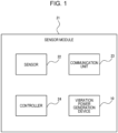
FIG. 1 is a functional block diagram schematically illustrating a sensor module that includes a vibration power generation device according to an embodiment. -
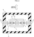
FIG. 2 is a cross-sectional view illustrating the vibration power generation device of the embodiment, which is cut in a vibration direction of the vibration power generation device. -
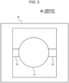
FIG. 3 is a top view illustrating the vibration power generation device ofFIG. 2 when the vibration power generation device is viewed in the vibration direction and a housing is removed. -
FIG. 4 is a top view illustrating a modification example of the vibration power generation device ofFIG. 2 when the vibration power generation device is viewed in the vibration direction and the housing is removed. -
FIG. 5 is a top view illustrating another modification example of the vibration power generation device ofFIG. 2 when the vibration power generation device is viewed in the vibration direction and the housing is removed. -
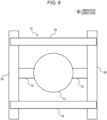
FIG. 6 is a top view illustrating another modification example of the vibration power generation device ofFIG. 2 when the vibration power generation device is viewed in the vibration direction and the housing is removed. -
FIG. 7 is a cross-sectional view illustrating an intermediate product of the vibration power generation device that is cut in the axial direction, the view being provided for the explanation of a fixation step of fixing beams to a fixation member according to a method of manufacturing the vibration power generation device ofFIG. 2 . -
FIG. 8 is a cross-sectional view illustrating an intermediate product of the vibration power generation device that is cut in the axial direction, the view being provided for the explanation of a step of attaching a weight to the beam according to the method of manufacturing the vibration power generation device ofFIG. 2 . -
FIG. 9 is a top view illustrating another modification example of the vibration power generation device ofFIG. 2 when the vibration power generation device is viewed in the vibration direction and the housing is removed. - An embodiment of the vibration power generation device according to the present disclosure is described with reference to the drawings.
- As illustrated in
FIG. 1 , a vibrationpower generation device 10 according to an embodiment of the present disclosure is disposed in asensor module 21. Thesensor module 21 includes asensor 22, acommunication unit 23, acontroller 24, and the vibrationpower generation device 10. Thesensor module 21 is configured to detect various states of things and transmits the detection results to an external device without receiving electric power from outside. Thesensor module 21 is applied to, for example, a bridge, a railroad car, a vehicle, a power plant, an outdoor machine, or a factory machine. - The
sensor 22 is configured to detect an arbitrary state of an arbitrary object. Examples of thesensor 22 are a vibration sensor, a temperature sensor, and a pressure sensor. Thesensor 22 is actuated by the electric power supplied from the vibrationpower generation device 10. - The
communication unit 23 includes a communication module for communication with an external device through a network. For example, thesensor 22 detects an arbitrary state of a thing, and thecommunication unit 23 transmits signals containing detection results to the external device. Thecommunication unit 23 may receive instructions from the external device and transmit the instructions to thecontroller 24. Thecommunication unit 23 is actuated by the electric power supplied from the vibrationpower generation device 10. - The
controller 24 includes one or more processors and a memory. The processor may be a general purpose processor that performs a specific function in accordance with a specific program provided or may be a special purpose processor dedicated to a specific function. The special purpose processor may include an application specific integrated circuit (ASIC). The processor may include a programmable logic device (PLD). The PLD may further include a field-programmable gate array (FPGA). Thecontroller 24 may be either a system in a package (SiP) or a system on a chip (SoC) in which one or more processors collaborate. Thecontroller 24 controls thesensor 22 and thecommunication unit 23. Thecontroller 24 is actuated by the electric power supplied from the vibrationpower generation device 10. - As illustrated in
FIG. 2 , the vibrationpower generation device 10 includes aweight 11, a plurality ofbeams 12,piezoelectric members 17, and afixation member 13. The vibrationpower generation device 10 may also include ahousing 14. - The
weight 11 provides inertia to thebeams 12 that are supported by the fixation member 13 (to be described later), thereby intensifying the vibration of thebeams 12. Theweight 11 may be disposed at a surface of the plurality ofbeams 12, the surface facing in the vibration direction in which the plurality ofbeams 12 vibrates. Theweight 11 may be disposed at opposite surfaces of the plurality ofbeams 12, the surfaces facing in the vibration direction. - The
weight 11 may include amain body 15 and aneck 16. As illustrated inFIG. 3 , themain body 15 is shaped like a circular plate. As illustrated inFIG. 2 , theneck 16 may be shaped like a column, such as a solid cylinder, that is thinner than themain body 15. The central axis of theneck 16 may pass through the center of the circularmain body 15 in a direction normal to the surface of themain body 15. Theneck 16 may be fixed to the plurality ofbeams 12 such that the central axis of theneck 16 extends parallel to the vibration direction. In the case where theweights 11 are disposed respectively at the opposite surfaces of the plurality ofbeams 12 that face in the vibration direction, twonecks 16 ofrespective weights 11 may be disposed such that the central axes of the twonecks 16 are aligned with a straight line. - As illustrated in
FIG. 3 , thebeams 12 extend from theweight 11 in different directions. In the present embodiment, twobeams 12 extend from theweight 11. As illustrated inFIG. 4 , fourbeams 12 may extend from theweight 11 in respective four directions. Each two of the fourbeams 12 may extend from theweight 11 in opposite directions so as to form a straight line. Each two of thebeams 12 extending from theweight 11 in the opposite directions may be made of a single member. As illustrated inFIG. 2 , the directions in whichrespective beams 12 extend are parallel to a single imaginary plane (in other words, a single plane). More specifically, thebeams 12 may extend in respective directions along the single imaginary plane. - The thickness of each
beam 12 in the vibration direction, in other words, in the direction normal to the imaginary plane, may be smaller than the width of thebeam 12. More specifically, thebeam 12 is a thin plate, and the principal surfaces of thebeam 12 extend orthogonal to the vibration direction. - The
beam 12 may be made of a metal, such as a stainless steel (SUS). - The
piezoelectric member 17 is disposed at eachbeam 12. Thepiezoelectric member 17 may be disposed at a position at which stress occurs to thepiezoelectric member 17 due to the vibration of thebeam 12. Thepiezoelectric members 17 may be disposed on the plane on which thebeams 12 are disposed. Eachpiezoelectric member 17 may be disposed on a surface of eachbeam 12 that faces in the vibration direction. Multiplepiezoelectric members 17 may be arranged side by side on asingle beam 12 in the extending direction of thebeam 12. Multiplepiezoelectric members 17 may be disposed respectively on opposite surfaces of eachbeam 12 that face in the vibration direction. - Each
piezoelectric member 17 includes an insulating film, a first electrode, a piezoelectric film, and a second electrode, which are laminated in this order from thebeam 12. The deformation of thebeam 12 due to vibration deforms thepiezoelectric member 17. Accordingly, when thebeam 12 vibrates, the piezoelectric film inside thepiezoelectric member 17 is subjected to stress, and the stress is converted into electric power due to the piezoelectric effect of the piezoelectric film. The electric power generated in the piezoelectric film is output to the first and the second electrodes and further to a device outside the vibrationpower generation device 10. - The
fixation member 13 includes at least a frame-shaped portion. The central axis of the frame-shaped portion of thefixation member 13 may extend in a direction perpendicular to the vibration direction, in other words, perpendicular to the direction normal to the above-described imaginary plane. Thefixation member 13 may be shaped entirely like a frame or may be shaped like a container in which one end of the frame-shaped portion in the axial direction is covered. The frame-shaped portion of thefixation member 13 may be shaped rectangularly. Alternatively, as illustrated inFIG. 5 , the frame-shaped portion of thefixation member 13 may be shaped circularly. Theweight 11 is entirely exposed from thefixation member 13 that is shaped entirely like the frame when thefixation member 13 is viewed in the vibration direction, in other words, viewed in the direction normal to the above-described imaginary plane. - The frame-shaped portion of the
fixation member 13 may include multiple sub-portions that form the frame. For example, as illustrated inFIG. 6 , the frame-shaped portion of thefixation member 13 may be made of twofixation members 18 to which thebeams 12 are fixed and twospacing adjustment members 19 that hold the twofixation members 18 apart from each other. - The
beams 12 are fixed to the frame-shaped portion of thefixation member 13 in such a manner that theweight 11 and thepiezoelectric members 17 are positioned inside the frame-shaped portion. Thebeams 12 are fixed to thefixation member 13 using an arbitrary method. As illustrated inFIG. 2 , thefixation member 13 may be made of a frame-shaped portion that can be separated into two parts, and thebeams 12 are nipped by the two parts in the vibration direction. - The
fixation member 13 is preferably made of a high-rigidity material. Examples of the material may be a metal such as Fe, an alloy containing Fe, Ni, and Cr as main components, a stainless steel (SUS), and a nonmetallic material such as a resin. - The
housing 14 may accommodate theweight 11 and thebeams 12. Thehousing 14 may support thefixation member 13. - Next, a method of manufacturing the vibration
power generation device 10 is described. As illustrated inFIG. 7 , eachbeam 12 is fixed to the frame-shapedfixation member 13 in such a manner that eachbeam 12 extends inward from the frame-shapedfixation member 13 so as to form a straight line with anotherbeam 12 or so as to intersect anotherbeam 12 inside the frame-shapedfixation member 13. Note that thepiezoelectric member 17 may be disposed at eachbeam 12 before thebeam 12 is fixed to thefixation member 13. Subsequently, as illustrated inFIG. 8 , theweight 11 is attached to thebeams 12 in the axial direction of the frame-shapedfixation member 13. - According to the present embodiment, the above-described vibration
power generation device 10 includes theweight 11, thebeams 12, thepiezoelectric members 17, and thefixation member 13. Thebeams 12 extend from theweight 11 in directions parallel to the single imaginary plane, and thepiezoelectric members 17 are disposed atrespective beams 12. Thefixation member 13 includes at least the frame-shaped portion. Thebeams 12 are fixed to the frame-shaped portion in such a manner that theweight 11 and thepiezoelectric members 17 are positioned inside the frame-shaped portion. In the case where the beams extending from the weight are fixed individually to the fixation member, the beams tend to warp vertically downward due to the presence of the weight. If the beams are warped before vibration, the output of the electric power decreases during vibration. In the vibrationpower generation device 10 according to the present embodiment, however, thebeams 12 are fixed to the frame-shaped portion of thefixation member 13, which can reduce relative displacement of the fixation positions along the imaginary plane, the imaginary plane being parallel to the extending directions ofunwarped beams 12. Accordingly, in the vibrationpower generation device 10, a reduction in the relative displacement of the fixation positions along the imaginary plane leads to a reduction in the amount of warp of thebeams 12. As a result, the vibrationpower generation device 10 can reduce the amount of warp of thebeams 12, which can increase the electricity output. - In the vibration
power generation device 10 of the present embodiment, the thickness of eachbeam 12 in the direction normal to the imaginary plane is smaller than the width of eachbeam 12. Accordingly, the vibrationpower generation device 10 generates vibrations easily in the direction normal to the imaginary plane. As a result, the vibrationpower generation device 10 increases the frequency with which the electric power is generated by thepiezoelectric members 17 disposed so as to face in the direction normal to the imaginary plane. - In addition, in the vibration
power generation device 10 of the present embodiment, thefixation member 13 is shaped entirely like the frame, and theweight 11 is entirely exposed from thefixation member 13 as viewed in the direction normal to the imaginary plane. According to this configuration, the vibrationpower generation device 10 can be manufactured such that thebeams 12 are first fixed to thefixation member 13 before theweight 11 is attached as illustrated inFIG. 7 , and subsequently theweight 11 is attached to thebeams 12 in the axial direction of the frame-shapedfixation member 13 as illustrated inFIG. 8 . Accordingly, in the vibrationpower generation device 10, thebeams 12 can be fixed to thefixation member 13 while the amount of warp of thebeams 12 caused by theweight 11 is reduced, which results in a further reduction in the amount of warp of thebeams 12 after theweight 11 is attached and accordingly results in an increase in the electricity output. - The present invention has been described with reference to the drawings and through examples. Note that those skilled in the art can modify and alter the embodiment easily on the basis of the present disclosure. Accordingly, such modifications and alterations are deemed within the scope of the invention.
- For example, in the present embodiment, the vibration
power generation device 10 includes twobeams 12 that extend from asingle weight 11 in opposite directions so as to form a straight line. The configuration of theweight 11 and thebeams 12 is not limited to this. For example, as illustrated inFIG. 9 , the vibrationpower generation device 10 may includemultiple sets 20 of theweight 11 and the twobeams 12 that extend from theweight 11 in opposite directions so as to form a straight line. Thebeams 12 included in each set 20 may be fixed to the frame-shaped portion of thefixation member 13. -
- 10
- vibration power generation device
- 11
- weight
- 12
- beam
- 13
- fixation member
- 14
- housing
- 15
- main body
- 16
- neck
- 17
- piezoelectric member
- 18
- fixation member
- 19
- spacing adjustment member
- 20
- set
- 21
- sensor module
- 22
- sensor
- 23
- communication unit
- 24
- controller
Claims (9)
- A vibration power generation device comprising:a weight;beams extending from the weight in directions parallel to a single plane;piezoelectric members disposed at respective beams; anda fixation member including at least a frame-shaped portion, whereinthe beams are fixed to the frame-shaped portion in such a manner that the weight and the piezoelectric members are positioned inside the frame-shaped portion.
- The vibration power generation device according to claim 1, wherein
a thickness of each beam in a direction normal to the plane is smaller than a width of each beam. - The vibration power generation device according to claim 1 or 2, wherein
the fixation member is shaped entirely like a frame. - The vibration power generation device according to claim 3, wherein
the weight is entirely exposed from the fixation member as viewed in the direction normal to the plane. - The vibration power generation device according to any one of claims 1 to 4, further comprising:
multiple sets of the weight and two of the beams, the two of the beams extending straight from the weight in opposite directions. - The vibration power generation device according to any one of claims 1 to 5, wherein
a central axis of the frame-shaped portion extends in a direction perpendicular to the directions of the beams extending from the weight. - A sensor module, comprising:the vibration power generation device according to any one of claims 1 to 6;a sensor actuated by electric power supplied from the vibration power generation device;a communication device actuated by the electric power supplied from the vibration power generation device and configured to communicate with an external device; anda controller actuated by the electric power supplied from the vibration power generation device and configured to control the sensor and the communication device.
- The sensor module according to claim 7, wherein
the sensor module is applied to a bridge, a railroad car, a vehicle, a power plant, an outdoor machine, or a factory machine. - A method of manufacturing the vibration power generation device, the method comprising:a step of fixing a beam to a fixation member shaped entirely like a frame in such a mannerthat the beam extends inward from the frame-shaped fixation member, andthat the beam forms a straight line with, or intersects, another beam inside the frame-shaped fixation member; anda step of attaching a weight to the beam in an axial direction of the frame-shaped fixation member.
Applications Claiming Priority (2)
| Application Number | Priority Date | Filing Date | Title |
|---|---|---|---|
| JP2020142035A JP2022037746A (en) | 2020-08-25 | 2020-08-25 | Vibration power generation device, sensor module, and manufacturing method |
| PCT/JP2021/031033 WO2022045148A1 (en) | 2020-08-25 | 2021-08-24 | Vibration power generation device, sensor module, and manufacturing method |
Publications (1)
| Publication Number | Publication Date |
|---|---|
| EP4207575A1 true EP4207575A1 (en) | 2023-07-05 |
Family
ID=80353714
Family Applications (1)
| Application Number | Title | Priority Date | Filing Date |
|---|---|---|---|
| EP21861572.2A Withdrawn EP4207575A1 (en) | 2020-08-25 | 2021-08-24 | Vibration power generation device, sensor module, and manufacturing method |
Country Status (5)
| Country | Link |
|---|---|
| US (1) | US20230336096A1 (en) |
| EP (1) | EP4207575A1 (en) |
| JP (1) | JP2022037746A (en) |
| CN (1) | CN115989627A (en) |
| WO (1) | WO2022045148A1 (en) |
Families Citing this family (1)
| Publication number | Priority date | Publication date | Assignee | Title |
|---|---|---|---|---|
| JP7379296B2 (en) * | 2020-08-25 | 2023-11-14 | 京セラ株式会社 | Vibration power generation device and sensor module |
Family Cites Families (6)
| Publication number | Priority date | Publication date | Assignee | Title |
|---|---|---|---|---|
| DE102007001361A1 (en) | 2007-01-09 | 2008-07-10 | Robert Bosch Gmbh | Energy generating device for a tire sensor module |
| JP5931472B2 (en) * | 2012-01-30 | 2016-06-08 | 株式会社ミツバ | Power generator |
| JP7395148B2 (en) * | 2015-09-10 | 2023-12-11 | 大日本印刷株式会社 | Mounting structure and power generation method of power generation device |
| EP3460981B1 (en) * | 2017-07-26 | 2022-03-30 | Tri-Force Management Corporation | Power generation element |
| JP7285424B2 (en) * | 2019-01-29 | 2023-06-02 | 住友金属鉱山株式会社 | Method for manufacturing vibration power generation device and method for manufacturing magnetostrictive part |
| CN111092567A (en) * | 2020-01-08 | 2020-05-01 | 广州大学 | Vibration power generation device |
-
2020
- 2020-08-25 JP JP2020142035A patent/JP2022037746A/en active Pending
-
2021
- 2021-08-24 EP EP21861572.2A patent/EP4207575A1/en not_active Withdrawn
- 2021-08-24 CN CN202180052571.8A patent/CN115989627A/en active Pending
- 2021-08-24 WO PCT/JP2021/031033 patent/WO2022045148A1/en not_active Ceased
- 2021-08-24 US US18/042,771 patent/US20230336096A1/en active Pending
Also Published As
| Publication number | Publication date |
|---|---|
| JP2022037746A (en) | 2022-03-09 |
| US20230336096A1 (en) | 2023-10-19 |
| CN115989627A (en) | 2023-04-18 |
| WO2022045148A1 (en) | 2022-03-03 |
Similar Documents
| Publication | Publication Date | Title |
|---|---|---|
| EP2485979B1 (en) | Method and device for energy harvesting | |
| EP4207575A1 (en) | Vibration power generation device, sensor module, and manufacturing method | |
| CN106763456A (en) | A kind of passive controllable isolation mounting of master based on piezoelectric photonic crystal | |
| WO2018066557A1 (en) | Sensor chip, strain inducing body, and force sensor device | |
| CN119002041A (en) | High-bandwidth MEMS scanning mirror device and design method thereof | |
| EP3460981B1 (en) | Power generation element | |
| JP5096918B2 (en) | Apparatus and method for influencing planar element vibration | |
| CN215773558U (en) | MEMS piezoelectric actuator and loudspeaker | |
| US10001375B2 (en) | Sensor device | |
| KR101067019B1 (en) | Energy Harvester Unit Module, Multi-Axis Energy Harvester Assembly Made By Combining It, Multi-Axis Energy Harvester Multiple Assembly Made By Combining It | |
| EP4207577A1 (en) | Vibration power generation device, sensor module, and manufacturing method | |
| JP2022142117A (en) | Sensor chip, and force sensor device | |
| US7459837B2 (en) | Broadband energy harvester apparatus and method | |
| EP4207576A1 (en) | Vibration power generation device and sensor module | |
| JP2025007464A (en) | Vibration power generation device | |
| EP4026797B1 (en) | Mems element and vibration-driven energy harvesting device | |
| JP2025007460A (en) | Vibration power generation device and sensor module | |
| JP6380944B1 (en) | Power generation element | |
| EP3808458A1 (en) | Vibration generating device | |
| US20250164325A1 (en) | Sensor module and force sensor device | |
| JP6998076B2 (en) | Force sensor | |
| US9032608B2 (en) | Method for manufacturing at least one mechanical-electrical energy conversion system | |
| JP2025007462A (en) | Vibration power generation device, manufacturing method for vibration power generation device, and sensor module | |
| JP2023081696A (en) | Vibration power generation device | |
| JP2005163915A (en) | Vibration resistant device |
Legal Events
| Date | Code | Title | Description |
|---|---|---|---|
| STAA | Information on the status of an ep patent application or granted ep patent |
Free format text: STATUS: THE INTERNATIONAL PUBLICATION HAS BEEN MADE |
|
| PUAI | Public reference made under article 153(3) epc to a published international application that has entered the european phase |
Free format text: ORIGINAL CODE: 0009012 |
|
| STAA | Information on the status of an ep patent application or granted ep patent |
Free format text: STATUS: REQUEST FOR EXAMINATION WAS MADE |
|
| 17P | Request for examination filed |
Effective date: 20230224 |
|
| AK | Designated contracting states |
Kind code of ref document: A1 Designated state(s): AL AT BE BG CH CY CZ DE DK EE ES FI FR GB GR HR HU IE IS IT LI LT LU LV MC MK MT NL NO PL PT RO RS SE SI SK SM TR |
|
| DAV | Request for validation of the european patent (deleted) | ||
| DAX | Request for extension of the european patent (deleted) | ||
| STAA | Information on the status of an ep patent application or granted ep patent |
Free format text: STATUS: THE APPLICATION HAS BEEN WITHDRAWN |
|
| 18W | Application withdrawn |
Effective date: 20240524 |