EP4207507A1 - Verbinderdichtungsanordnung, verbinder und verbinderanordnung - Google Patents
Verbinderdichtungsanordnung, verbinder und verbinderanordnung Download PDFInfo
- Publication number
- EP4207507A1 EP4207507A1 EP22216949.2A EP22216949A EP4207507A1 EP 4207507 A1 EP4207507 A1 EP 4207507A1 EP 22216949 A EP22216949 A EP 22216949A EP 4207507 A1 EP4207507 A1 EP 4207507A1
- Authority
- EP
- European Patent Office
- Prior art keywords
- cable
- seal
- housing
- connector
- peripheral wall
- Prior art date
- Legal status (The legal status is an assumption and is not a legal conclusion. Google has not performed a legal analysis and makes no representation as to the accuracy of the status listed.)
- Pending
Links
- 238000007789 sealing Methods 0.000 title claims abstract description 57
- 230000013011 mating Effects 0.000 claims abstract description 29
- 230000002093 peripheral effect Effects 0.000 claims description 80
- 230000004308 accommodation Effects 0.000 claims description 47
- 230000004048 modification Effects 0.000 description 2
- 238000012986 modification Methods 0.000 description 2
- 230000007717 exclusion Effects 0.000 description 1
Images


Classifications
-
- H—ELECTRICITY
- H01—ELECTRIC ELEMENTS
- H01R—ELECTRICALLY-CONDUCTIVE CONNECTIONS; STRUCTURAL ASSOCIATIONS OF A PLURALITY OF MUTUALLY-INSULATED ELECTRICAL CONNECTING ELEMENTS; COUPLING DEVICES; CURRENT COLLECTORS
- H01R13/00—Details of coupling devices of the kinds covered by groups H01R12/70 or H01R24/00 - H01R33/00
- H01R13/46—Bases; Cases
- H01R13/52—Dustproof, splashproof, drip-proof, waterproof, or flameproof cases
- H01R13/5205—Sealing means between cable and housing, e.g. grommet
- H01R13/5208—Sealing means between cable and housing, e.g. grommet having at least two cable receiving openings
-
- H—ELECTRICITY
- H01—ELECTRIC ELEMENTS
- H01R—ELECTRICALLY-CONDUCTIVE CONNECTIONS; STRUCTURAL ASSOCIATIONS OF A PLURALITY OF MUTUALLY-INSULATED ELECTRICAL CONNECTING ELEMENTS; COUPLING DEVICES; CURRENT COLLECTORS
- H01R13/00—Details of coupling devices of the kinds covered by groups H01R12/70 or H01R24/00 - H01R33/00
- H01R13/46—Bases; Cases
- H01R13/502—Bases; Cases composed of different pieces
-
- H—ELECTRICITY
- H01—ELECTRIC ELEMENTS
- H01R—ELECTRICALLY-CONDUCTIVE CONNECTIONS; STRUCTURAL ASSOCIATIONS OF A PLURALITY OF MUTUALLY-INSULATED ELECTRICAL CONNECTING ELEMENTS; COUPLING DEVICES; CURRENT COLLECTORS
- H01R13/00—Details of coupling devices of the kinds covered by groups H01R12/70 or H01R24/00 - H01R33/00
- H01R13/46—Bases; Cases
- H01R13/52—Dustproof, splashproof, drip-proof, waterproof, or flameproof cases
- H01R13/5202—Sealing means between parts of housing or between housing part and a wall, e.g. sealing rings
-
- H—ELECTRICITY
- H01—ELECTRIC ELEMENTS
- H01R—ELECTRICALLY-CONDUCTIVE CONNECTIONS; STRUCTURAL ASSOCIATIONS OF A PLURALITY OF MUTUALLY-INSULATED ELECTRICAL CONNECTING ELEMENTS; COUPLING DEVICES; CURRENT COLLECTORS
- H01R13/00—Details of coupling devices of the kinds covered by groups H01R12/70 or H01R24/00 - H01R33/00
- H01R13/46—Bases; Cases
- H01R13/52—Dustproof, splashproof, drip-proof, waterproof, or flameproof cases
- H01R13/5205—Sealing means between cable and housing, e.g. grommet
-
- H—ELECTRICITY
- H01—ELECTRIC ELEMENTS
- H01R—ELECTRICALLY-CONDUCTIVE CONNECTIONS; STRUCTURAL ASSOCIATIONS OF A PLURALITY OF MUTUALLY-INSULATED ELECTRICAL CONNECTING ELEMENTS; COUPLING DEVICES; CURRENT COLLECTORS
- H01R13/00—Details of coupling devices of the kinds covered by groups H01R12/70 or H01R24/00 - H01R33/00
- H01R13/46—Bases; Cases
- H01R13/52—Dustproof, splashproof, drip-proof, waterproof, or flameproof cases
- H01R13/521—Sealing between contact members and housing, e.g. sealing insert
-
- H—ELECTRICITY
- H01—ELECTRIC ELEMENTS
- H01R—ELECTRICALLY-CONDUCTIVE CONNECTIONS; STRUCTURAL ASSOCIATIONS OF A PLURALITY OF MUTUALLY-INSULATED ELECTRICAL CONNECTING ELEMENTS; COUPLING DEVICES; CURRENT COLLECTORS
- H01R13/00—Details of coupling devices of the kinds covered by groups H01R12/70 or H01R24/00 - H01R33/00
- H01R13/648—Protective earth or shield arrangements on coupling devices, e.g. anti-static shielding
- H01R13/658—High frequency shielding arrangements, e.g. against EMI [Electro-Magnetic Interference] or EMP [Electro-Magnetic Pulse]
- H01R13/6581—Shield structure
-
- H—ELECTRICITY
- H01—ELECTRIC ELEMENTS
- H01R—ELECTRICALLY-CONDUCTIVE CONNECTIONS; STRUCTURAL ASSOCIATIONS OF A PLURALITY OF MUTUALLY-INSULATED ELECTRICAL CONNECTING ELEMENTS; COUPLING DEVICES; CURRENT COLLECTORS
- H01R24/00—Two-part coupling devices, or either of their cooperating parts, characterised by their overall structure
- H01R24/20—Coupling parts carrying sockets, clips or analogous contacts and secured only to wire or cable
-
- H—ELECTRICITY
- H01—ELECTRIC ELEMENTS
- H01R—ELECTRICALLY-CONDUCTIVE CONNECTIONS; STRUCTURAL ASSOCIATIONS OF A PLURALITY OF MUTUALLY-INSULATED ELECTRICAL CONNECTING ELEMENTS; COUPLING DEVICES; CURRENT COLLECTORS
- H01R27/00—Coupling parts adapted for co-operation with two or more dissimilar counterparts
- H01R27/02—Coupling parts adapted for co-operation with two or more dissimilar counterparts for simultaneous co-operation with two or more dissimilar counterparts
Definitions
- the present invention relates to a connector sealing assembly, a connector including the connector sealing assembly, and a connector assembly including the connector.
- a connector for a laser radar generally includes an outer housing, an inner housing provided in the outer housing, and terminals provided in the inner housing for transmitting signals (e.g., Ethernet signals) and power.
- signals e.g., Ethernet signals
- it is usually necessary to set a cable seal in the inner housing, and the cable seal is sleeved on the cable to realize the sealing between the cable and the housing.
- it is also necessary to provide a housing seal in the outer housing.
- the present invention has been made to overcome or alleviate at least one aspect of the above mentioned disadvantages.
- a connector sealing assembly comprising of: an outer housing in which a plurality of seal mounting portions are provided; a cable seal mounted on a cable seal mounting portion of the plurality of seal mounting portions for realizing the sealing between the outer housing and a cable extending into the outer housing; and a housing seal mounted on a housing seal mounting portion of the plurality of seal mounting portions for realizing the sealing between the outer housing and a mating housing of a mating connector.
- the cable seal comprises of: a first cable seal for sealing some cables of a connector; and / or a second cable seal for sealing other cables of the connector.
- the outer housing is formed with: a first accommodation chamber for accommodating the first cable seal, and a chamber wall of the first accommodation chamber is sealingly engaged with the first cable seal; and a second accommodation chamber for accommodating the second cable seal, and a chamber wall of the second accommodation chamber is sealingly engaged with the second cable seal.
- the connector sealing assembly further comprises a protection end cap inserted into an opening of the first accommodation chamber and fixed to the outer housing for holding the first cable seal in the first accommodation chamber.
- the outer housing comprises of: an outer peripheral wall; an inner peripheral wall radially spaced from the outer peripheral wall; and a radial side wall connected between the outer peripheral wall and the inner peripheral wall.
- the inner peripheral wall separates the first accommodation chamber from the second accommodation chamber, a third accommodation chamber for accommodating the housing seal is defined by the outer peripheral wall, the inner peripheral wall and the radial side wall.
- the housing seal is provided on the outer side of the inner peripheral wall and is sealingly engaged with the inner peripheral wall.
- the housing seal is a seal ring and is sleeved on the outer peripheral surface of the inner peripheral wall; an outer peripheral surface of the housing seal is radially spaced apart from an inner peripheral surface of the outer peripheral wall by a predetermined gap to allow the mating housing to be inserted between the housing seal and the outer peripheral wall.
- the cable seal is adapted to simultaneously seal a plurality of different types and / or a plurality of different sizes of cables; the cable seal is formed with a plurality of different cable through holes adapted to mate with a plurality of different types and / or a plurality of different sizes of cables respectively.
- the cable seal comprises a first cable seal and a second cable seal, at least two different cable through holes are formed in at least one of the first cable seal and the second cable seal.
- a slot is formed on the inner peripheral wall of the outer housing, and the slot is adapted to engage with a protrusion formed on an inner housing of the connector to fix the inner housing to the outer housing.
- the connector sealing assembly comprises an outer housing in which a first accommodation chamber and a second accommodation chamber are formed for installing a first cable seal and a second cable seal, respectively.
- the outer housing comprises of: an outer peripheral wall in which a chamber is formed for accommodating an inner housing of a connector; an inner peripheral wall radially spaced from the outer peripheral wall to form a third accommodation chamber for accommodating a housing seal; and a radial side wall connected between the outer peripheral wall and the inner peripheral wall.
- a housing seal mounting portion for mounting the housing seal is formed on an outer wall surface of the inner peripheral wall.
- cable seal mounting portions for mounting a first cable seal and a second cable seal are formed on an inner wall surface of the inner peripheral wall.
- a connector comprising of: the above connector sealing assembly; and an inner housing at least partially received in the outer housing.
- the connector further comprises a cable extending into the outer housing and the inner housing and passing through the cable seal, the cable includes a signal cable for transmitting signals and a power cable for transmitting power.
- the cable comprises of: a first cable for transmitting a first signal; a second cable for transmitting a second signal different from the first signal; and a third cable for transmitting power.
- the connector further comprises of: a first terminal provided in the inner housing and electrically connected to the first cable; a second terminal provided in the inner housing and electrically connected to the second cable; and a third terminal provided in the inner housing and electrically connected to the third cable.
- the connector further comprises a shield arranged in the inner housing, the first cable is an Ethernet cable for transmitting Ethernet signals, the shield is electrically connected to the shield layer of the first cable, and the first terminal is at least partially accommodated in the shield.
- the cable seal includes a first cable seal and a second cable seal; a first cable through hole adapted to mate with the first cable is formed in the first cable seal; a second cable through hole adapted to mate with the second cable and a third cable through hole adapted to mate with the third cable are formed in the second cable seal.
- the outer diameter of the first cable is larger than the outer diameter of the second cable and the third cable, and the inner diameter of the first cable through hole is larger than the inner diameter of the second cable through hole and the third cable through hole; the outer diameter of the third cable is larger than the outer diameter of the second cable, and the inner diameter of the third cable through hole is larger than the inner diameter of the second cable through hole.
- the first cable seal is a seal ring and is sleeved on the first cable;
- the second cable seal includes a block shaped sealing body in which the second cable through hole and the third cable through hole are formed.
- the connector further comprises a shield connecting spring piece, which is installed on the inner housing, and is used to electrically connect the shield of the connector and a mating shield of a mating connector.
- a connector assembly comprising of: the above connector; and a mating connector adapted to mate with the connector.
- both the cable seal and the housing seal are provided in the outer housing, so that the size of the connector can be reduced, and the difficulty of installing the cable seal can be reduced and the sealing reliability can be improved.
- a connector sealing assembly comprises of: an outer housing in which a plurality of seal mounting portions are provided; a cable seal mounted on a cable seal mounting portion of the plurality of seal mounting portions for realizing the sealing between the outer housing and a cable extending into the outer housing; and a housing seal mounted on a housing seal mounting portion of the plurality of seal mounting portions for realizing the sealing between the outer housing and a mating housing of a mating connector.
- the connector sealing assembly comprises an outer housing in which a first accommodation chamber and a second accommodation chamber are formed for installing a first cable seal and a second cable seal, respectively.
- the outer housing comprises of: an outer peripheral wall in which a chamber is formed for accommodating an inner housing of a connector; an inner peripheral wall radially spaced from the outer peripheral wall to form a third accommodation chamber for accommodating a housing seal; and a radial side wall connected between the outer peripheral wall and the inner peripheral wall.
- the outer housing is formed to a single integral piece.
- a connector comprising of: the above connector sealing assembly; and an inner housing at least partially received in the outer housing.
- Fig. 1 shows an illustrative perspective view of a connector according to an exemplary embodiment of the present invention.
- Fig. 2 shows a longitudinal sectional view of a connector according to an exemplary embodiment of the present invention.
- Fig. 3 shows another longitudinal cross-sectional view of a connector according to an exemplary embodiment of the present invention with the inner housing 200 removed.
- Fig. 4 shows an exploded schematic view of the outer housing 100, the cable seals 110, 120, and the housing seal 130 of the connector according to an exemplary embodiment of the present invention.
- a connector suitable for connection with, for example, a laser radar includes a power terminal for transmitting power and a signal terminal for transmitting signals.
- the connector includes a connector sealing assembly, an inner housing 200 and cables 1, 2, 3.
- the connector sealing assembly includes an outer housing 100, cable seals 110 and 120, and a housing seal 130.
- the inner housing 200 is at least partially accommodated in the outer housing 100.
- the cables 1, 2, 3 extend into the outer housing 100 and the inner housing 200 and pass through the cable seals 110, 120.
- a plurality of seal mounting portions 101a, 102a, and 112b are provided inside the outer housing 100.
- the cable seals 110 and 120 are mounted on the cable seal mounting portions 101a and 102a of the plurality of seal mounting portions 101a, 102a and 112b, and are used to realize the sealing between the outer housing 100 and the cables 1, 2 and 3 extending into the outer housing 100.
- the housing seal 130 is mounted on the housing seal mounting portion 112b of the plurality of seal mounting portions 101a, 102a, and 112b, and is used to realize the sealing between the outer housing 100 and the mating housing of the mating connector.
- Fig. 5 shows an illustrative assembly view of the outer housing 100, the cable seals 110, 120 and the housing seal 130 of the connector according to an exemplary embodiment of the present invention.
- the cable seals 110 and 120 are accommodated in the outer housing 100 to realize the sealing between the outer housing 100 and the cables 1, 2 and 3 extending into the outer housing 100.
- the housing seal 130 is accommodated in the outer housing 100 for realize the sealing between the outer housing 100 and the mating housing (not shown) of the mating connector (not shown).
- the cable seals 110 and 120 include a first cable seal 110 and a second cable seal 120.
- the first cable seal 110 is used to seal some cables 1 of the connector.
- the second cable seal 120 is used to seal other cables 2, 3 of the connector.
- a first accommodation chamber 101, a second accommodation chamber 102, and a third accommodation chamber 103 are formed in the outer housing 100.
- the first accommodation chamber 101 is used to accommodate the first cable seal 110, and the chamber wall of the first accommodation chamber 101 is sealingly engaged with the first cable seal 110.
- the second accommodation chamber 102 is used to accommodate the second cable seal 120, and the chamber wall of the second accommodation chamber 102 is sealingly engaged with the second cable seal 120.
- the third accommodation chamber 103 is used to accommodate the housing seal 130.
- the first accommodation chamber 101, the second accommodation chamber 102 and the third accommodation chamber 103 in the outer housing 100 are isolated from each other.
- the connector sealing assembly further includes a protection end cap 40.
- the protection end cap 40 is inserted into an opening of the first accommodation chamber 101 and fixed to the outer housing 100, which is used to hold the first cable seal 110 in the first accommodation chamber 101 to prevent the first cable seal 110 from being pulled out of the first accommodation chamber 101.
- the outer housing 100 includes an outer peripheral wall 111, an inner peripheral wall 112, and a radial side wall 113.
- the inner peripheral wall 112 is radially spaced from the outer peripheral wall 111.
- the radial side wall 113 is connected between one end of the outer peripheral wall 111 and the inner peripheral wall 112.
- the first accommodation chamber 101 and the second accommodation chamber 102 are surrounded by the inner peripheral wall 112 and isolated from each other.
- the third accommodation chamber 103 is defined between the outer peripheral wall 111, the inner peripheral wall 112 and the radial side wall 113.
- the housing seal 130 is provided on the outer side of the inner peripheral wall 112 and is sealingly engaged with the inner peripheral wall 112.
- a slot 112a is formed on the inner peripheral wall 112 of the outer housing 100.
- the slot 112a is adapted to engage with the protrusion 212a formed on the inner housing 200 of the connector to fix the inner housing 200 to the outer housing 100.
- the fixing feature between the outer housing 100 and the inner housing 200 is not limited to the illustrated embodiment, and other suitable features may be adopted.
- the housing seal 130 is a seal ring and is fitted on the outer peripheral surface of the inner peripheral wall 112.
- the outer peripheral surface of the housing seal 130 is radially spaced apart from the inner peripheral surface of the outer peripheral wall 111 of the outer housing 100 by a predetermined gap to allow the mating housing of the mating connector to be inserted between the housing seal 130 and the outer peripheral wall 111 of the outer housing 100. That is, the housing seal 130 is radially pressed between the mating housing of the mating connector and the outer peripheral wall 111 of the outer housing 100, thereby achieving a seal between them.
- Fig. 6 shows an illustrative assembly view of cables 1, 2, 3 and cable seals 110, 120 of a connector according to an exemplary embodiment of the present invention
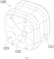
- Fig. 7 shows an illustrative perspective view of the second cable seal 120 shown in Fig. 6 .
- the cable seals 110, 120 are adapted to simultaneously seal a plurality of different types and / or a plurality of different sizes of cables 1, 2, 3.
- a plurality of different cable through holes 122, 123 may be formed in the cable seals 110, 120, which are adapted to mate with a plurality of different types and / or a plurality of different sizes of cables 1, 2, 3, respectively.
- the cable seals 110 and 120 include a first cable seal 110 and a second cable seal 120. At least two different cable through holes 122 and 123 are formed on at least one of the first cable seal 110 and the second cable seal 120 for mating with at least two different types and / or different sizes of cables 2 and 3.
- a connector is also disclosed.
- the connector includes the aforementioned connector sealing assembly, an inner housing 200, and cables 1, 2, and 3.
- the inner housing 200 is at least partially accommodated in the outer housing 100.
- the cables 1, 2, 3 extend into the outer housing 100 and the inner housing 200 and pass through the cable seals 110 and 120.
- the cables 1, 2, and 3 include a signal cable 1, 2 for transmitting signals and a power cable 3 for transmitting power.
- the connector is a hybrid connector suitable for simultaneously transmitting signals and power.
- the connector may be a hybrid connector for connecting with a laser radar.
- the cables 1, 2, and 3 include a first cable 1, a second cable 2, and a third cable 3.
- the first cable 1 is used to transmit a first signal, for example, an Ethernet signal.
- the second cable 2 is used for transmitting a second signal different from the first signal, for example, for transmitting a LAN signal.
- the third cable 3 is used to transmit power.
- the connector further includes a first terminal 10, a second terminal 20, and a third terminal 30.
- the first terminal 10 is provided in the inner housing 200 and electrically connected to the first cable 1.
- the second terminal 20 is provided in the inner housing 200 and electrically connected to the second cable 2.
- the third terminal 30 is provided in the inner housing 200 and electrically connected to the third cable 3.
- the first cable 1 is an Ethernet cable for transmitting Ethernet signals
- the connector further includes a shield 11 provided in the inner housing 200.
- the shield 11 is electrically connected to the shield layer of the first cable 1, and the first terminal 10 is at least partially accommodated in the shield 11.
- electromagnetic shielding can be provided for the first terminal 10 to prevent signal interference.
- the connector further comprises a pair of shield connecting spring pieces (not shown).
- a pair of shield connecting spring pieces are respectively mounted on both sides of the inner housing 200 for electrically connecting the shield 11 of the connector and a mating shield (not shown) of the mating connector.
- the cable seals 110 and 120 include a first cable seal 110 and a second cable seal 120.
- a first cable through hole adapted to mate with the first cable 1 is formed in the first cable seal 110.
- a second cable through hole 122 adapted to mate with the second cable 2 and a third cable through hole 123 adapted to mate with the third cable 3 are formed in the second cable seal 120.
- the outer diameter of the first cable 1 is larger than that of the second cable 2 and the third cable 3, and the inner diameter of the first cable through hole is larger than that of the second cable through hole 122 and the third cable through hole 123.
- the outer diameter of the third cable 3 is larger than the outer diameter of the second cable 2, and the inner diameter of the third cable through hole 123 is larger than the inner diameter of the second cable through hole 122.
- the first cable seal 110 is a seal ring and is sleeved on the first cable 1.
- the second cable seal 120 includes a block shaped sealing body 121.
- the second cable through hole 122 and the third cable through hole 123 are formed in the sealing body 121.
- a connector sealing assembly is also disclosed, and the connector sealing assembly includes an outer housing 100.
- the outer housing 100 is provided with a first accommodation chamber 101 and a second accommodation chamber 102 for installing the first cable seal 110 and the second cable seal 120, respectively.
- the outer housing 100 comprises of an outer peripheral wall 111, and a chamber 104 is formed inside the outer peripheral wall 111 to accommodate the inner housing 200 of the connector; an inner peripheral wall 112 radially spaced from the outer peripheral wall 111 to form a third accommodation chamber 103 for accommodating the housing seal 130; and a radial side wall 113 connected to the outer peripheral wall 111 and the inner peripheral wall 112.
- the outer housing 100 is formed into a single integral piece.
- a housing seal mounting portion 112b is formed on the outer wall surface of the inner peripheral wall 112 for mounting the housing seal 130.
- the inner wall surface of the inner peripheral wall 112 is formed with cable seal mounting portions 101a and 102a for mounting the first cable seal 110 and the second cable seal 120 respectively.
- a connector assembly including the aforementioned connector and a mating connector (not shown) adapted to mate with the aforementioned connector.
Landscapes
- Connector Housings Or Holding Contact Members (AREA)
Applications Claiming Priority (1)
| Application Number | Priority Date | Filing Date | Title |
|---|---|---|---|
| CN202111659649.0A CN116417840A (zh) | 2021-12-31 | 2021-12-31 | 连接器密封组件、连接器和连接器组件 |
Publications (1)
| Publication Number | Publication Date |
|---|---|
| EP4207507A1 true EP4207507A1 (de) | 2023-07-05 |
Family
ID=84688406
Family Applications (1)
| Application Number | Title | Priority Date | Filing Date |
|---|---|---|---|
| EP22216949.2A Pending EP4207507A1 (de) | 2021-12-31 | 2022-12-28 | Verbinderdichtungsanordnung, verbinder und verbinderanordnung |
Country Status (5)
| Country | Link |
|---|---|
| US (1) | US20230216238A1 (de) |
| EP (1) | EP4207507A1 (de) |
| JP (1) | JP2023099498A (de) |
| KR (1) | KR20230104052A (de) |
| CN (1) | CN116417840A (de) |
Citations (7)
| Publication number | Priority date | Publication date | Assignee | Title |
|---|---|---|---|---|
| FR2786033A1 (fr) * | 1998-11-17 | 2000-05-19 | Whitaker Corp | Dispositif d'etancheite pour connecteurs de cables et assemblage de connecteur |
| WO2007131534A1 (en) * | 2006-05-12 | 2007-11-22 | Fci | Sealed electrical connector and process for manufacturing the same |
| US7371115B1 (en) * | 2006-12-15 | 2008-05-13 | Delphi Technologies, Inc. | Mat seal device |
| US20150155670A1 (en) * | 2012-07-23 | 2015-06-04 | Molex Incorporated | Electrical harness connector system with differential pair connection link |
| US20150295346A1 (en) * | 2014-04-09 | 2015-10-15 | Delphi Technologies, Inc. | Sealed connector with an extended seal sleeve and an anti-water pooling retainer |
| US20190393656A1 (en) * | 2018-06-25 | 2019-12-26 | Foxconn (Kunshan) Computer Connector Co., Ltd. | Cable connector assembly |
| US20200194938A1 (en) * | 2018-12-12 | 2020-06-18 | Hyundai Motor Company | Integrated multipole connector |
-
2021
- 2021-12-31 CN CN202111659649.0A patent/CN116417840A/zh active Pending
-
2022
- 2022-12-26 JP JP2022207715A patent/JP2023099498A/ja active Pending
- 2022-12-28 EP EP22216949.2A patent/EP4207507A1/de active Pending
- 2022-12-29 US US18/147,794 patent/US20230216238A1/en active Pending
- 2022-12-30 KR KR1020220190264A patent/KR20230104052A/ko unknown
Patent Citations (7)
| Publication number | Priority date | Publication date | Assignee | Title |
|---|---|---|---|---|
| FR2786033A1 (fr) * | 1998-11-17 | 2000-05-19 | Whitaker Corp | Dispositif d'etancheite pour connecteurs de cables et assemblage de connecteur |
| WO2007131534A1 (en) * | 2006-05-12 | 2007-11-22 | Fci | Sealed electrical connector and process for manufacturing the same |
| US7371115B1 (en) * | 2006-12-15 | 2008-05-13 | Delphi Technologies, Inc. | Mat seal device |
| US20150155670A1 (en) * | 2012-07-23 | 2015-06-04 | Molex Incorporated | Electrical harness connector system with differential pair connection link |
| US20150295346A1 (en) * | 2014-04-09 | 2015-10-15 | Delphi Technologies, Inc. | Sealed connector with an extended seal sleeve and an anti-water pooling retainer |
| US20190393656A1 (en) * | 2018-06-25 | 2019-12-26 | Foxconn (Kunshan) Computer Connector Co., Ltd. | Cable connector assembly |
| US20200194938A1 (en) * | 2018-12-12 | 2020-06-18 | Hyundai Motor Company | Integrated multipole connector |
Also Published As
| Publication number | Publication date |
|---|---|
| JP2023099498A (ja) | 2023-07-13 |
| CN116417840A (zh) | 2023-07-11 |
| US20230216238A1 (en) | 2023-07-06 |
| KR20230104052A (ko) | 2023-07-07 |
Similar Documents
| Publication | Publication Date | Title |
|---|---|---|
| US10090623B2 (en) | Enclosure assembly for a connector | |
| KR101083449B1 (ko) | 고전압 차폐 전기 커넥터 조립체 | |
| US7785129B2 (en) | RF connector having sealing member | |
| US9570831B2 (en) | Retaining structure for terminal fitting | |
| KR20100083701A (ko) | 커넥터 | |
| US20120045175A1 (en) | Plug assembly | |
| WO2012157503A1 (ja) | 防水コネクタ | |
| EP4207505A1 (de) | Hybridsteckergehäuse, hybridstecker und steckeranordnung | |
| CN216672020U (zh) | 连接器密封组件、连接器和连接器组件 | |
| EP4207507A1 (de) | Verbinderdichtungsanordnung, verbinder und verbinderanordnung | |
| KR100800789B1 (ko) | 실드 커넥터 | |
| EP4207508A1 (de) | Verbindergehäuseanordnung, verbinder und verbinderanordnung | |
| EP2866305B1 (de) | Steckverbinder | |
| EP4207509A1 (de) | Schutzendabdeckung, verbinder und verbinderanordnung | |
| CN216671983U (zh) | 连接器壳体组件、连接器和连接器组件 | |
| CN110061390B (zh) | 一种防错紧固型密封接插件 | |
| EP4116133A1 (de) | Verbindergehäuseanordnung und -verbinder | |
| EP4307488A1 (de) | Verbindergehäuse und verbinder | |
| EP4312316A1 (de) | Subverbinder, verbinder und verbinderanordnung | |
| CN218448613U (zh) | 连接器和连接器组件 | |
| EP4343973A1 (de) | Verbinderanordnung und elektrische verbindungsanordnung | |
| EP4243213A1 (de) | Verbinder und verbinderanordnung | |
| CN113471761B (zh) | 插头连接器和插座连接器 | |
| US20230062211A1 (en) | Connectors and Connector Assembly | |
| US20220140539A1 (en) | Male Connector, Female Connector and Connector Assembly |
Legal Events
| Date | Code | Title | Description |
|---|---|---|---|
| PUAI | Public reference made under article 153(3) epc to a published international application that has entered the european phase |
Free format text: ORIGINAL CODE: 0009012 |
|
| STAA | Information on the status of an ep patent application or granted ep patent |
Free format text: STATUS: THE APPLICATION HAS BEEN PUBLISHED |
|
| AK | Designated contracting states |
Kind code of ref document: A1 Designated state(s): AL AT BE BG CH CY CZ DE DK EE ES FI FR GB GR HR HU IE IS IT LI LT LU LV MC ME MK MT NL NO PL PT RO RS SE SI SK SM TR |
|
| STAA | Information on the status of an ep patent application or granted ep patent |
Free format text: STATUS: REQUEST FOR EXAMINATION WAS MADE |
|
| 17P | Request for examination filed |
Effective date: 20240104 |
|
| RBV | Designated contracting states (corrected) |
Designated state(s): AL AT BE BG CH CY CZ DE DK EE ES FI FR GB GR HR HU IE IS IT LI LT LU LV MC ME MK MT NL NO PL PT RO RS SE SI SK SM TR |