EP4207341A1 - Multilayer electrode and lithium secondary battery including the same - Google Patents
Multilayer electrode and lithium secondary battery including the same Download PDFInfo
- Publication number
- EP4207341A1 EP4207341A1 EP23154762.1A EP23154762A EP4207341A1 EP 4207341 A1 EP4207341 A1 EP 4207341A1 EP 23154762 A EP23154762 A EP 23154762A EP 4207341 A1 EP4207341 A1 EP 4207341A1
- Authority
- EP
- European Patent Office
- Prior art keywords
- conductive material
- electrode mixture
- mixture layer
- electrode
- porosity
- Prior art date
- Legal status (The legal status is an assumption and is not a legal conclusion. Google has not performed a legal analysis and makes no representation as to the accuracy of the status listed.)
- Pending
Links
- 229910052744 lithium Inorganic materials 0.000 title claims abstract description 18
- WHXSMMKQMYFTQS-UHFFFAOYSA-N Lithium Chemical compound [Li] WHXSMMKQMYFTQS-UHFFFAOYSA-N 0.000 title claims abstract description 17
- 239000004020 conductor Substances 0.000 claims abstract description 185
- 239000000203 mixture Substances 0.000 claims abstract description 172
- 239000002245 particle Substances 0.000 claims abstract description 42
- 239000011148 porous material Substances 0.000 claims abstract description 37
- OKTJSMMVPCPJKN-UHFFFAOYSA-N Carbon Chemical group [C] OKTJSMMVPCPJKN-UHFFFAOYSA-N 0.000 claims description 25
- 239000011149 active material Substances 0.000 claims description 25
- 229910052782 aluminium Inorganic materials 0.000 claims description 14
- XAGFODPZIPBFFR-UHFFFAOYSA-N aluminium Chemical compound [Al] XAGFODPZIPBFFR-UHFFFAOYSA-N 0.000 claims description 12
- 229910052802 copper Inorganic materials 0.000 claims description 8
- 239000010949 copper Substances 0.000 claims description 8
- RYGMFSIKBFXOCR-UHFFFAOYSA-N Copper Chemical compound [Cu] RYGMFSIKBFXOCR-UHFFFAOYSA-N 0.000 claims description 7
- BQCADISMDOOEFD-UHFFFAOYSA-N Silver Chemical compound [Ag] BQCADISMDOOEFD-UHFFFAOYSA-N 0.000 claims description 6
- 239000006230 acetylene black Substances 0.000 claims description 6
- 229910021383 artificial graphite Inorganic materials 0.000 claims description 6
- 239000003273 ketjen black Substances 0.000 claims description 6
- 229910021382 natural graphite Inorganic materials 0.000 claims description 6
- 229910052709 silver Inorganic materials 0.000 claims description 6
- 239000004332 silver Substances 0.000 claims description 6
- 239000006232 furnace black Substances 0.000 claims description 5
- 239000002041 carbon nanotube Substances 0.000 claims description 4
- 229910021393 carbon nanotube Inorganic materials 0.000 claims description 4
- 239000007772 electrode material Substances 0.000 claims 2
- 238000007599 discharging Methods 0.000 abstract description 7
- 239000010410 layer Substances 0.000 description 152
- HBBGRARXTFLTSG-UHFFFAOYSA-N Lithium ion Chemical compound [Li+] HBBGRARXTFLTSG-UHFFFAOYSA-N 0.000 description 26
- 229910001416 lithium ion Inorganic materials 0.000 description 26
- SECXISVLQFMRJM-UHFFFAOYSA-N N-Methylpyrrolidone Chemical compound CN1CCCC1=O SECXISVLQFMRJM-UHFFFAOYSA-N 0.000 description 16
- 239000011230 binding agent Substances 0.000 description 14
- 238000009792 diffusion process Methods 0.000 description 13
- 238000000034 method Methods 0.000 description 13
- 239000002002 slurry Substances 0.000 description 11
- 239000002033 PVDF binder Substances 0.000 description 10
- 239000006182 cathode active material Substances 0.000 description 10
- 229920002981 polyvinylidene fluoride Polymers 0.000 description 10
- 230000008569 process Effects 0.000 description 10
- 239000006257 cathode slurry Substances 0.000 description 8
- CXULZQWIHKYPTP-UHFFFAOYSA-N cobalt(2+) manganese(2+) nickel(2+) oxygen(2-) Chemical compound [O--].[O--].[O--].[Mn++].[Co++].[Ni++] CXULZQWIHKYPTP-UHFFFAOYSA-N 0.000 description 8
- 230000000052 comparative effect Effects 0.000 description 8
- 239000007787 solid Substances 0.000 description 8
- 239000002904 solvent Substances 0.000 description 8
- 238000001035 drying Methods 0.000 description 7
- PXHVJJICTQNCMI-UHFFFAOYSA-N Nickel Chemical compound [Ni] PXHVJJICTQNCMI-UHFFFAOYSA-N 0.000 description 6
- 239000011888 foil Substances 0.000 description 6
- -1 aluminum-cadmium Chemical compound 0.000 description 5
- 230000015572 biosynthetic process Effects 0.000 description 5
- 150000002500 ions Chemical class 0.000 description 5
- KAKZBPTYRLMSJV-UHFFFAOYSA-N Butadiene Chemical compound C=CC=C KAKZBPTYRLMSJV-UHFFFAOYSA-N 0.000 description 4
- 229910052799 carbon Inorganic materials 0.000 description 4
- 230000000694 effects Effects 0.000 description 4
- 229910052742 iron Inorganic materials 0.000 description 4
- 229910052759 nickel Inorganic materials 0.000 description 4
- 239000002131 composite material Substances 0.000 description 3
- 150000001875 compounds Chemical class 0.000 description 3
- 230000007423 decrease Effects 0.000 description 3
- 239000000463 material Substances 0.000 description 3
- 229920002943 EPDM rubber Polymers 0.000 description 2
- VYPSYNLAJGMNEJ-UHFFFAOYSA-N Silicium dioxide Chemical compound O=[Si]=O VYPSYNLAJGMNEJ-UHFFFAOYSA-N 0.000 description 2
- PPBRXRYQALVLMV-UHFFFAOYSA-N Styrene Chemical group C=CC1=CC=CC=C1 PPBRXRYQALVLMV-UHFFFAOYSA-N 0.000 description 2
- RTAQQCXQSZGOHL-UHFFFAOYSA-N Titanium Chemical compound [Ti] RTAQQCXQSZGOHL-UHFFFAOYSA-N 0.000 description 2
- KLARSDUHONHPRF-UHFFFAOYSA-N [Li].[Mn] Chemical compound [Li].[Mn] KLARSDUHONHPRF-UHFFFAOYSA-N 0.000 description 2
- 229910045601 alloy Inorganic materials 0.000 description 2
- 239000000956 alloy Substances 0.000 description 2
- 230000008901 benefit Effects 0.000 description 2
- WMWLMWRWZQELOS-UHFFFAOYSA-N bismuth(iii) oxide Chemical compound O=[Bi]O[Bi]=O WMWLMWRWZQELOS-UHFFFAOYSA-N 0.000 description 2
- 229910052796 boron Inorganic materials 0.000 description 2
- CQEYYJKEWSMYFG-UHFFFAOYSA-N butyl acrylate Chemical compound CCCCOC(=O)C=C CQEYYJKEWSMYFG-UHFFFAOYSA-N 0.000 description 2
- 229920001940 conductive polymer Polymers 0.000 description 2
- 238000011161 development Methods 0.000 description 2
- GNTDGMZSJNCJKK-UHFFFAOYSA-N divanadium pentaoxide Chemical compound O=[V](=O)O[V](=O)=O GNTDGMZSJNCJKK-UHFFFAOYSA-N 0.000 description 2
- 229920001971 elastomer Polymers 0.000 description 2
- 239000003792 electrolyte Substances 0.000 description 2
- YBMRDBCBODYGJE-UHFFFAOYSA-N germanium dioxide Chemical compound O=[Ge]=O YBMRDBCBODYGJE-UHFFFAOYSA-N 0.000 description 2
- 229910000625 lithium cobalt oxide Inorganic materials 0.000 description 2
- BFZPBUKRYWOWDV-UHFFFAOYSA-N lithium;oxido(oxo)cobalt Chemical compound [Li+].[O-][Co]=O BFZPBUKRYWOWDV-UHFFFAOYSA-N 0.000 description 2
- 229910052748 manganese Inorganic materials 0.000 description 2
- 239000011572 manganese Substances 0.000 description 2
- 238000004519 manufacturing process Methods 0.000 description 2
- 238000003825 pressing Methods 0.000 description 2
- 238000004904 shortening Methods 0.000 description 2
- 229910052710 silicon Inorganic materials 0.000 description 2
- 229910001220 stainless steel Inorganic materials 0.000 description 2
- 239000010935 stainless steel Substances 0.000 description 2
- XOLBLPGZBRYERU-UHFFFAOYSA-N tin dioxide Chemical compound O=[Sn]=O XOLBLPGZBRYERU-UHFFFAOYSA-N 0.000 description 2
- 229910052719 titanium Inorganic materials 0.000 description 2
- 239000010936 titanium Substances 0.000 description 2
- 229910052725 zinc Inorganic materials 0.000 description 2
- 229920002134 Carboxymethyl cellulose Polymers 0.000 description 1
- 229910000925 Cd alloy Inorganic materials 0.000 description 1
- 229910018039 Cu2V2O7 Inorganic materials 0.000 description 1
- 229910017010 Fe2 (MoO4)3 Inorganic materials 0.000 description 1
- YCKRFDGAMUMZLT-UHFFFAOYSA-N Fluorine atom Chemical compound [F] YCKRFDGAMUMZLT-UHFFFAOYSA-N 0.000 description 1
- 229920002153 Hydroxypropyl cellulose Polymers 0.000 description 1
- 229910000733 Li alloy Inorganic materials 0.000 description 1
- 229910007969 Li-Co-Ni Inorganic materials 0.000 description 1
- 229910006570 Li1+xMn2-xO4 Inorganic materials 0.000 description 1
- 229910006628 Li1+xMn2−xO4 Inorganic materials 0.000 description 1
- 229910003349 Li2CuO2 Inorganic materials 0.000 description 1
- 229910010228 Li2Mn3MO8 Inorganic materials 0.000 description 1
- 229910010521 LiFe3O4 Inorganic materials 0.000 description 1
- 229910014172 LiMn2-xMxO2 Inorganic materials 0.000 description 1
- 229910014774 LiMn2O3 Inorganic materials 0.000 description 1
- 229910014437 LiMn2−XMXO2 Inorganic materials 0.000 description 1
- 229910002993 LiMnO2 Inorganic materials 0.000 description 1
- 229910014713 LiMnO3 Inorganic materials 0.000 description 1
- 229910014114 LiNi1-xMxO2 Inorganic materials 0.000 description 1
- 229910014907 LiNi1−xMxO2 Inorganic materials 0.000 description 1
- 229910013649 LiNixMn2-xO4 Inorganic materials 0.000 description 1
- 229910013663 LiNixMn2—xO4 Inorganic materials 0.000 description 1
- 229910012970 LiV3O8 Inorganic materials 0.000 description 1
- 229910002097 Lithium manganese(III,IV) oxide Inorganic materials 0.000 description 1
- 229910016622 LixFe2O3 Inorganic materials 0.000 description 1
- 229910015103 LixWO2 Inorganic materials 0.000 description 1
- 229910006555 Li—Co—Ni Inorganic materials 0.000 description 1
- 241000237536 Mytilus edulis Species 0.000 description 1
- 239000004698 Polyethylene Substances 0.000 description 1
- 239000004743 Polypropylene Substances 0.000 description 1
- 239000004372 Polyvinyl alcohol Substances 0.000 description 1
- BLRPTPMANUNPDV-UHFFFAOYSA-N Silane Chemical compound [SiH4] BLRPTPMANUNPDV-UHFFFAOYSA-N 0.000 description 1
- XUIMIQQOPSSXEZ-UHFFFAOYSA-N Silicon Chemical compound [Si] XUIMIQQOPSSXEZ-UHFFFAOYSA-N 0.000 description 1
- 229920002472 Starch Polymers 0.000 description 1
- ATJFFYVFTNAWJD-UHFFFAOYSA-N Tin Chemical compound [Sn] ATJFFYVFTNAWJD-UHFFFAOYSA-N 0.000 description 1
- GWEVSGVZZGPLCZ-UHFFFAOYSA-N Titan oxide Chemical compound O=[Ti]=O GWEVSGVZZGPLCZ-UHFFFAOYSA-N 0.000 description 1
- QDDVNKWVBSLTMB-UHFFFAOYSA-N [Cu]=O.[Li] Chemical compound [Cu]=O.[Li] QDDVNKWVBSLTMB-UHFFFAOYSA-N 0.000 description 1
- SOXUFMZTHZXOGC-UHFFFAOYSA-N [Li].[Mn].[Co].[Ni] Chemical compound [Li].[Mn].[Co].[Ni] SOXUFMZTHZXOGC-UHFFFAOYSA-N 0.000 description 1
- XHCLAFWTIXFWPH-UHFFFAOYSA-N [O-2].[O-2].[O-2].[O-2].[O-2].[V+5].[V+5] Chemical compound [O-2].[O-2].[O-2].[O-2].[O-2].[V+5].[V+5] XHCLAFWTIXFWPH-UHFFFAOYSA-N 0.000 description 1
- FDLZQPXZHIFURF-UHFFFAOYSA-N [O-2].[Ti+4].[Li+] Chemical compound [O-2].[Ti+4].[Li+] FDLZQPXZHIFURF-UHFFFAOYSA-N 0.000 description 1
- 238000003915 air pollution Methods 0.000 description 1
- 229910001420 alkaline earth metal ion Inorganic materials 0.000 description 1
- HSFWRNGVRCDJHI-UHFFFAOYSA-N alpha-acetylene Natural products C#C HSFWRNGVRCDJHI-UHFFFAOYSA-N 0.000 description 1
- 239000006183 anode active material Substances 0.000 description 1
- 239000010405 anode material Substances 0.000 description 1
- LJCFOYOSGPHIOO-UHFFFAOYSA-N antimony pentoxide Inorganic materials O=[Sb](=O)O[Sb](=O)=O LJCFOYOSGPHIOO-UHFFFAOYSA-N 0.000 description 1
- 229910000411 antimony tetroxide Inorganic materials 0.000 description 1
- GHPGOEFPKIHBNM-UHFFFAOYSA-N antimony(3+);oxygen(2-) Chemical compound [O-2].[O-2].[O-2].[Sb+3].[Sb+3] GHPGOEFPKIHBNM-UHFFFAOYSA-N 0.000 description 1
- 229910000417 bismuth pentoxide Inorganic materials 0.000 description 1
- 239000003575 carbonaceous material Substances 0.000 description 1
- 230000015556 catabolic process Effects 0.000 description 1
- 239000010406 cathode material Substances 0.000 description 1
- 229910052804 chromium Inorganic materials 0.000 description 1
- 229910052681 coesite Inorganic materials 0.000 description 1
- 238000010276 construction Methods 0.000 description 1
- 150000004696 coordination complex Chemical class 0.000 description 1
- 239000011889 copper foil Substances 0.000 description 1
- 229910052906 cristobalite Inorganic materials 0.000 description 1
- 238000005520 cutting process Methods 0.000 description 1
- 230000003247 decreasing effect Effects 0.000 description 1
- 238000006731 degradation reaction Methods 0.000 description 1
- 230000006866 deterioration Effects 0.000 description 1
- 150000002019 disulfides Chemical class 0.000 description 1
- 230000007613 environmental effect Effects 0.000 description 1
- 238000011156 evaluation Methods 0.000 description 1
- 230000001747 exhibiting effect Effects 0.000 description 1
- 229910052731 fluorine Inorganic materials 0.000 description 1
- 239000011737 fluorine Substances 0.000 description 1
- 229910052733 gallium Inorganic materials 0.000 description 1
- 229910052732 germanium Inorganic materials 0.000 description 1
- PVADDRMAFCOOPC-UHFFFAOYSA-N germanium monoxide Inorganic materials [Ge]=O PVADDRMAFCOOPC-UHFFFAOYSA-N 0.000 description 1
- 229910021389 graphene Inorganic materials 0.000 description 1
- 229910052736 halogen Inorganic materials 0.000 description 1
- 150000002367 halogens Chemical class 0.000 description 1
- 229910021385 hard carbon Inorganic materials 0.000 description 1
- 239000001863 hydroxypropyl cellulose Substances 0.000 description 1
- 235000010977 hydroxypropyl cellulose Nutrition 0.000 description 1
- 229910052745 lead Inorganic materials 0.000 description 1
- YADSGOSSYOOKMP-UHFFFAOYSA-N lead dioxide Inorganic materials O=[Pb]=O YADSGOSSYOOKMP-UHFFFAOYSA-N 0.000 description 1
- YEXPOXQUZXUXJW-UHFFFAOYSA-N lead(II) oxide Inorganic materials [Pb]=O YEXPOXQUZXUXJW-UHFFFAOYSA-N 0.000 description 1
- XMFOQHDPRMAJNU-UHFFFAOYSA-N lead(II,IV) oxide Inorganic materials O1[Pb]O[Pb]11O[Pb]O1 XMFOQHDPRMAJNU-UHFFFAOYSA-N 0.000 description 1
- 239000001989 lithium alloy Substances 0.000 description 1
- 229910002102 lithium manganese oxide Inorganic materials 0.000 description 1
- QEXMICRJPVUPSN-UHFFFAOYSA-N lithium manganese(2+) oxygen(2-) Chemical class [O-2].[Mn+2].[Li+] QEXMICRJPVUPSN-UHFFFAOYSA-N 0.000 description 1
- VROAXDSNYPAOBJ-UHFFFAOYSA-N lithium;oxido(oxo)nickel Chemical compound [Li+].[O-][Ni]=O VROAXDSNYPAOBJ-UHFFFAOYSA-N 0.000 description 1
- URIIGZKXFBNRAU-UHFFFAOYSA-N lithium;oxonickel Chemical compound [Li].[Ni]=O URIIGZKXFBNRAU-UHFFFAOYSA-N 0.000 description 1
- 229910052749 magnesium Inorganic materials 0.000 description 1
- 229910052751 metal Inorganic materials 0.000 description 1
- 239000002184 metal Substances 0.000 description 1
- 229910044991 metal oxide Inorganic materials 0.000 description 1
- 150000004706 metal oxides Chemical class 0.000 description 1
- 238000012986 modification Methods 0.000 description 1
- 230000004048 modification Effects 0.000 description 1
- 235000020638 mussel Nutrition 0.000 description 1
- 238000005457 optimization Methods 0.000 description 1
- 230000000737 periodic effect Effects 0.000 description 1
- 229910052698 phosphorus Inorganic materials 0.000 description 1
- 229920001197 polyacetylene Polymers 0.000 description 1
- 229920000573 polyethylene Polymers 0.000 description 1
- 229920000642 polymer Polymers 0.000 description 1
- 229920000098 polyolefin Polymers 0.000 description 1
- 229920001155 polypropylene Polymers 0.000 description 1
- 229920002451 polyvinyl alcohol Polymers 0.000 description 1
- 229920000036 polyvinylpyrrolidone Polymers 0.000 description 1
- 239000001267 polyvinylpyrrolidone Substances 0.000 description 1
- 235000013855 polyvinylpyrrolidone Nutrition 0.000 description 1
- 239000000843 powder Substances 0.000 description 1
- 102000004169 proteins and genes Human genes 0.000 description 1
- 108090000623 proteins and genes Proteins 0.000 description 1
- 230000009467 reduction Effects 0.000 description 1
- 239000004627 regenerated cellulose Substances 0.000 description 1
- 238000011160 research Methods 0.000 description 1
- 238000001878 scanning electron micrograph Methods 0.000 description 1
- 229910000077 silane Inorganic materials 0.000 description 1
- 239000010703 silicon Substances 0.000 description 1
- 239000000377 silicon dioxide Substances 0.000 description 1
- LIVNPJMFVYWSIS-UHFFFAOYSA-N silicon monoxide Inorganic materials [Si-]#[O+] LIVNPJMFVYWSIS-UHFFFAOYSA-N 0.000 description 1
- 239000002210 silicon-based material Substances 0.000 description 1
- 239000002356 single layer Substances 0.000 description 1
- 229910021384 soft carbon Inorganic materials 0.000 description 1
- 229910052596 spinel Inorganic materials 0.000 description 1
- 239000011029 spinel Substances 0.000 description 1
- 239000008107 starch Substances 0.000 description 1
- 235000019698 starch Nutrition 0.000 description 1
- 229910052682 stishovite Inorganic materials 0.000 description 1
- 239000000126 substance Substances 0.000 description 1
- 239000000758 substrate Substances 0.000 description 1
- 229920005608 sulfonated EPDM Polymers 0.000 description 1
- 229910052715 tantalum Inorganic materials 0.000 description 1
- BFKJFAAPBSQJPD-UHFFFAOYSA-N tetrafluoroethene Chemical group FC(F)=C(F)F BFKJFAAPBSQJPD-UHFFFAOYSA-N 0.000 description 1
- QHGNHLZPVBIIPX-UHFFFAOYSA-N tin(II) oxide Inorganic materials [Sn]=O QHGNHLZPVBIIPX-UHFFFAOYSA-N 0.000 description 1
- OGIDPMRJRNCKJF-UHFFFAOYSA-N titanium oxide Inorganic materials [Ti]=O OGIDPMRJRNCKJF-UHFFFAOYSA-N 0.000 description 1
- 238000012546 transfer Methods 0.000 description 1
- 229910052723 transition metal Inorganic materials 0.000 description 1
- 150000003624 transition metals Chemical class 0.000 description 1
- 229910052905 tridymite Inorganic materials 0.000 description 1
- 229910001935 vanadium oxide Inorganic materials 0.000 description 1
- 239000011701 zinc Substances 0.000 description 1
Images


Classifications
-
- H—ELECTRICITY
- H01—ELECTRIC ELEMENTS
- H01M—PROCESSES OR MEANS, e.g. BATTERIES, FOR THE DIRECT CONVERSION OF CHEMICAL ENERGY INTO ELECTRICAL ENERGY
- H01M4/00—Electrodes
- H01M4/02—Electrodes composed of, or comprising, active material
- H01M4/64—Carriers or collectors
- H01M4/66—Selection of materials
- H01M4/665—Composites
- H01M4/667—Composites in the form of layers, e.g. coatings
-
- H—ELECTRICITY
- H01—ELECTRIC ELEMENTS
- H01M—PROCESSES OR MEANS, e.g. BATTERIES, FOR THE DIRECT CONVERSION OF CHEMICAL ENERGY INTO ELECTRICAL ENERGY
- H01M4/00—Electrodes
- H01M4/02—Electrodes composed of, or comprising, active material
- H01M4/36—Selection of substances as active materials, active masses, active liquids
- H01M4/362—Composites
- H01M4/366—Composites as layered products
-
- H—ELECTRICITY
- H01—ELECTRIC ELEMENTS
- H01M—PROCESSES OR MEANS, e.g. BATTERIES, FOR THE DIRECT CONVERSION OF CHEMICAL ENERGY INTO ELECTRICAL ENERGY
- H01M4/00—Electrodes
- H01M4/02—Electrodes composed of, or comprising, active material
- H01M4/13—Electrodes for accumulators with non-aqueous electrolyte, e.g. for lithium-accumulators; Processes of manufacture thereof
- H01M4/133—Electrodes based on carbonaceous material, e.g. graphite-intercalation compounds or CFx
-
- H—ELECTRICITY
- H01—ELECTRIC ELEMENTS
- H01M—PROCESSES OR MEANS, e.g. BATTERIES, FOR THE DIRECT CONVERSION OF CHEMICAL ENERGY INTO ELECTRICAL ENERGY
- H01M10/00—Secondary cells; Manufacture thereof
- H01M10/05—Accumulators with non-aqueous electrolyte
- H01M10/052—Li-accumulators
-
- H—ELECTRICITY
- H01—ELECTRIC ELEMENTS
- H01M—PROCESSES OR MEANS, e.g. BATTERIES, FOR THE DIRECT CONVERSION OF CHEMICAL ENERGY INTO ELECTRICAL ENERGY
- H01M4/00—Electrodes
- H01M4/02—Electrodes composed of, or comprising, active material
- H01M4/04—Processes of manufacture in general
- H01M4/0402—Methods of deposition of the material
- H01M4/0404—Methods of deposition of the material by coating on electrode collectors
-
- H—ELECTRICITY
- H01—ELECTRIC ELEMENTS
- H01M—PROCESSES OR MEANS, e.g. BATTERIES, FOR THE DIRECT CONVERSION OF CHEMICAL ENERGY INTO ELECTRICAL ENERGY
- H01M4/00—Electrodes
- H01M4/02—Electrodes composed of, or comprising, active material
- H01M4/04—Processes of manufacture in general
- H01M4/043—Processes of manufacture in general involving compressing or compaction
- H01M4/0435—Rolling or calendering
-
- H—ELECTRICITY
- H01—ELECTRIC ELEMENTS
- H01M—PROCESSES OR MEANS, e.g. BATTERIES, FOR THE DIRECT CONVERSION OF CHEMICAL ENERGY INTO ELECTRICAL ENERGY
- H01M4/00—Electrodes
- H01M4/02—Electrodes composed of, or comprising, active material
- H01M4/62—Selection of inactive substances as ingredients for active masses, e.g. binders, fillers
- H01M4/624—Electric conductive fillers
- H01M4/625—Carbon or graphite
-
- H—ELECTRICITY
- H01—ELECTRIC ELEMENTS
- H01M—PROCESSES OR MEANS, e.g. BATTERIES, FOR THE DIRECT CONVERSION OF CHEMICAL ENERGY INTO ELECTRICAL ENERGY
- H01M4/00—Electrodes
- H01M4/02—Electrodes composed of, or comprising, active material
- H01M4/62—Selection of inactive substances as ingredients for active masses, e.g. binders, fillers
- H01M4/624—Electric conductive fillers
- H01M4/626—Metals
-
- H—ELECTRICITY
- H01—ELECTRIC ELEMENTS
- H01M—PROCESSES OR MEANS, e.g. BATTERIES, FOR THE DIRECT CONVERSION OF CHEMICAL ENERGY INTO ELECTRICAL ENERGY
- H01M4/00—Electrodes
- H01M4/02—Electrodes composed of, or comprising, active material
- H01M4/64—Carriers or collectors
- H01M4/66—Selection of materials
-
- H—ELECTRICITY
- H01—ELECTRIC ELEMENTS
- H01M—PROCESSES OR MEANS, e.g. BATTERIES, FOR THE DIRECT CONVERSION OF CHEMICAL ENERGY INTO ELECTRICAL ENERGY
- H01M4/00—Electrodes
- H01M4/02—Electrodes composed of, or comprising, active material
- H01M4/64—Carriers or collectors
- H01M4/70—Carriers or collectors characterised by shape or form
- H01M4/80—Porous plates, e.g. sintered carriers
-
- H—ELECTRICITY
- H01—ELECTRIC ELEMENTS
- H01M—PROCESSES OR MEANS, e.g. BATTERIES, FOR THE DIRECT CONVERSION OF CHEMICAL ENERGY INTO ELECTRICAL ENERGY
- H01M10/00—Secondary cells; Manufacture thereof
- H01M10/05—Accumulators with non-aqueous electrolyte
- H01M10/052—Li-accumulators
- H01M10/0525—Rocking-chair batteries, i.e. batteries with lithium insertion or intercalation in both electrodes; Lithium-ion batteries
-
- H—ELECTRICITY
- H01—ELECTRIC ELEMENTS
- H01M—PROCESSES OR MEANS, e.g. BATTERIES, FOR THE DIRECT CONVERSION OF CHEMICAL ENERGY INTO ELECTRICAL ENERGY
- H01M4/00—Electrodes
- H01M4/02—Electrodes composed of, or comprising, active material
- H01M2004/021—Physical characteristics, e.g. porosity, surface area
-
- H—ELECTRICITY
- H01—ELECTRIC ELEMENTS
- H01M—PROCESSES OR MEANS, e.g. BATTERIES, FOR THE DIRECT CONVERSION OF CHEMICAL ENERGY INTO ELECTRICAL ENERGY
- H01M4/00—Electrodes
- H01M4/02—Electrodes composed of, or comprising, active material
- H01M2004/026—Electrodes composed of, or comprising, active material characterised by the polarity
- H01M2004/027—Negative electrodes
-
- Y—GENERAL TAGGING OF NEW TECHNOLOGICAL DEVELOPMENTS; GENERAL TAGGING OF CROSS-SECTIONAL TECHNOLOGIES SPANNING OVER SEVERAL SECTIONS OF THE IPC; TECHNICAL SUBJECTS COVERED BY FORMER USPC CROSS-REFERENCE ART COLLECTIONS [XRACs] AND DIGESTS
- Y02—TECHNOLOGIES OR APPLICATIONS FOR MITIGATION OR ADAPTATION AGAINST CLIMATE CHANGE
- Y02E—REDUCTION OF GREENHOUSE GAS [GHG] EMISSIONS, RELATED TO ENERGY GENERATION, TRANSMISSION OR DISTRIBUTION
- Y02E60/00—Enabling technologies; Technologies with a potential or indirect contribution to GHG emissions mitigation
- Y02E60/10—Energy storage using batteries
Definitions
- the present disclosure relates to a multilayer electrode and a lithium secondary battery including the same, and more particularly, to a multilayer electrode comprised of a plurality of electrode mixture layers including a conductive material having different average particle diameters and porosity, and a lithium secondary battery including the same.
- lithium secondary batteries exhibiting high energy density and operating potential and which have a long cycle life and a low self-discharge rate, have been commercialized and widely used.
- EVs electric vehicles
- HEVs hybrid electric vehicles
- Lithium secondary batteries having high energy density, high discharge voltage and output stability have mainly been researched and used as power sources for electric vehicles (EVs) and hybrid electric vehicles (HEVs).
- Such a lithium secondary battery is under development as a model capable of implementing a high voltage and a high capacity in line with consumer demand.
- a lithium secondary battery is required to have an optimization process of a cathode material, an anode material, a separator, and an electrolyte, four elements of the lithium secondary battery, within a limited space.
- an electrode for a secondary battery is produced by preparing a slurry in which an active material and a binder, and as required, a conductive material, are mixed, and then applying the slurry to a collector, such as a copper foil, as a single layer, followed by drying.
- a collector such as a copper foil
- an active material powder is pressed onto a current collector and a pressing process is performed to uniformize the thickness of an electrode.
- An aspect of the present disclosure is to provide a multilayer electrode having a multilayer structure in which diffusion of ions may be facilitated by including a conductive material which has electric conductivity similar to that of a commonly used conductive material and has a relatively large average particle diameter and pores in the conductive material itself, and to provide a lithium secondary battery including the same.
- a multilayer electrode includes a current collector, a first electrode mixture layer disposed on at least one surface of the current collector, and a second electrode mixture layer disposed on the first electrode mixture layer.
- the first and second electrode mixture layers include one or more types of conductive materials, and a porosity of the conductive material contained in the second electrode mixture layer is greater than a porosity of the conductive material contained in the first electrode mixture layer.
- the porosity of the conductive material contained in the first electrode mixture layer may be 0 to 30%, and the porosity of the conductive material contained in the second electrode mixture layer may be 50 to 90%.
- An average particle diameter of the conductive material contained in the second electrode mixture layer may be greater than an average particle diameter of the conductive material contained in the first electrode mixture layer.
- the average particle diameter of the conductive material contained in the first electrode mixture layer may be 0.01 to 0.5 ⁇ m, and the average particle diameter of the conductive material contained in the second electrode mixture layer may be 0.5 to 5 ⁇ m.
- An average pore diameter of the conductive material contained in the first electrode mixture layer may be 0 to 0.01 ⁇ m, and an average pore diameter of the conductive material contained in the second electrode mixture layer may be 0.01 to 0.5 ⁇ m.
- the conductive material may be one or more selected from carbon black, acetylene black, furnace black, ketjen black, carbon nanotubes, artificial graphite, natural graphite, silver, aluminum and copper.
- a thickness of the second electrode mixture layer may be 20 to 80% of a total thickness of the first and second electrode mixture layers.
- a content of the conductive material contained in the second electrode mixture layer may be more than 0.5 wt% to less than 5 wt% of a total active material content of the first and second electrode mixture layers.
- a multilayer electrode includes a current collector, a first electrode mixture layer disposed on at least one surface of the current collector, and a second electrode mixture layer disposed on the first electrode mixture layer.
- the first and second electrode mixture layers include a first conductive material and a second conductive material having a porosity greater than a porosity of the first electrode mixture layer, and a content of the second conductive material contained in the second electrode mixture layer is greater than a content of the second conductive material contained in the first electrode mixture layer.
- the porosity of the conductive material contained in the first electrode mixture layer may be 0 to 30%, and the porosity of the conductive material contained in the second electrode mixture layer may be 50 to 90%.
- An average particle diameter of the conductive material contained in the second electrode mixture layer may be greater than an average particle diameter of the conductive material contained in the first electrode mixture layer.
- the average particle diameter of the conductive material contained in the first electrode mixture layer may be 0.01 to 0.5 ⁇ m, and the average particle diameter of the conductive material contained in the second electrode mixture layer may be 0.5 to 5 um.
- An average pore diameter of the conductive material contained in the first electrode mixture layer may be 0 to 0.01 ⁇ m, and an average pore diameter of the conductive material contained in the second electrode mixture layer may be 0.01 to 0.5 ⁇ m.
- the conductive material may be one or more selected from carbon black, acetylene black, furnace black, ketjen black, carbon nanotubes, artificial graphite, natural graphite, silver, aluminum and copper.
- a thickness of the second electrode mixture layer may be 20 to 80% of a total thickness of the first and second electrode mixture layers.
- a content of the conductive material contained in the second electrode mixture layer may be more than 0.5 wt% to less than 5 wt% of a total active material content of the first and second electrode mixture layers.
- a lithium secondary battery includes the multilayer electrode as described above.
- a multilayer electrode comprised of a plurality of electrode mixture layers, including conductive materials having different average particle diameters and porosity, and a lithium secondary battery including the same, are provided.
- the thickness of an electrode has increased and the density of an electrode mixture layer has increased.
- the thickness and density of the electrode increase, the movement of electrons and the movement of lithium ions are restricted, resulting in a problem such as performance degradation in output characteristics and a high rate of a battery.
- a multilayer electrode including a porous conductive material which has an electric conductivity similar to that of a generally used conductive material and has a relatively large average particle diameter and pores in the conductive material itself, to be capable of facilitating movement of lithium ions, may be provided.
- a multilayer electrode includes a current collector 10, a first electrode mixture layer 110 formed on at least one surface of the current collector 10, and a second electrode mixture layer 130 formed on the first electrode mixture layer.
- the first and second electrode mixture layers 110 and 130 include a conductive material.
- the porosity of a conductive material contained in the second electrode mixture layer 130 is greater than the porosity of a conductive material contained in the first electrode mixture layer 110.
- the conductive material is added to impart conductivity without causing chemical changes in a battery.
- the conductivity increases, but as the conductive material having a smaller average particle diameter and a lower density than those of an active material is present in a relatively large amount in the material mixture layer, the porosity of an electrode is decreased and movement distances of ions increases, based on the same mixture layer weight, a restriction on the movement of the lithium ions occurs, causing a problem such as deterioration in performance of output characteristics and a high rate of a battery.
- a multilayer electrode including the first and second electrode mixture layers sequentially stacked on a current collector, is configured in such a manner that the porosity of a conductive material contained in the second electrode mixture layer is greater than the porosity of a conductive material contained in the first electrode mixture layer, and thus, movement of lithium ions may be smooth.
- the porosity of the conductive material contained in the first electrode mixture layer is 0 to 30%
- the porosity of the conductive material contained in the second electrode mixture layer may be 50 to 90%, in more detail, 60 to 80%. If the porosity of the conductive material contained in the second electrode mixture layer is less than 50%, the function thereof may be difficult to serve as a movement path of lithium ions. If the porosity of the conductive material contained in the second electrode mixture layer exceeds 90%, it is difficult to maintain the conductive material form, and thus, the conductive material may easily break during a calendeing process and the function thereof may also be difficult to serve as a movement path of lithium ions.
- the shape of the conductive material is not particularly limited, but may be spherical.
- an average particle diameter of the conductive material included in the second electrode mixture layer may be greater than an average particle diameter of the conductive material contained in the first electrode mixture layer.
- an average particle diameter D 50 of the conductive material contained in the first electrode mixture layer is 0.01 to 0.5 ⁇ m
- an average particle diameter of the conductive material contained in the second electrode mixture layer is 0.5 to 5 ⁇ m, in more detail, 1 to 3 ⁇ m. If the average particle diameter D 50 of the conductive material contained in the second electrode mixture layer is less than 0.5 ⁇ m, since the conductive material may only fill pores between active material particles, it may be difficult to sufficiently perform the role of relatively shortening the movement path of lithium ions. If the average particle diameter D 50 of the conductive material contained in the second electrode mixture layer exceeds 0.5 ⁇ m, as a surface area of the conductive material decreases, electrical contact resistance between active material particles, as well as between active material particles and current collector particles, may increase.
- An average pore diameter of the conductive material contained in the second electrode mixture layer may be greater than an average pore diameter of the conductive material contained in the first electrode mixture layer.
- the average pore diameter of the conductive material contained in the first electrode mixture layer may be 0 to 0.01 ⁇ m
- the average pore diameter of the conductive material contained in the second electrode mixture layer may be 0.01 to 0.5 ⁇ m, in detail, 0.05 to 0.3 ⁇ m. If the average pore diameter of the conductive material contained in the second electrode mixture layer is less than 0.01 um, the radius of the lithium ion diffusion path may be reduced, so that a diffusion rate of lithium ions through the pores of the conductive material is significantly reduced. If the average pore diameter of the conductive material contained in the second electrode mixture layer exceeds 0.5 ⁇ m, strength of a conductive material layer may be reduced and the conductive material layer may be easily cracked during a calendeing process.
- Examples of the conductive material contained in the first and second electrode mixture layers in an embodiment include carbon such as carbon black, acetylene black, furnace black, ketjen black, artificial graphite, natural graphite or the like, and a metal such as silver, aluminum, copper or the like.
- carbon such as carbon black, acetylene black, furnace black, ketjen black, artificial graphite, natural graphite or the like
- metal such as silver, aluminum, copper or the like.
- a material of the first and second electrode mixture layers only one kind of conductive material having different porosity and different average particle diameters may be used, or two or more conductive materials may be used in which the porosity and an average particle diameter of a plurality of conductive materials in the second electrode mixture layer may be greater than the porosity and an average particle diameter of the conductive material contained in the first electrode mixture layer.
- the content of the conductive material contained in the second electrode mixture layer may be more than 0.5 wt% to less than 5 wt% of the total active material content of the electrode mixture layer. If the content of the conductive material contained in the second electrode mixture layer is 0.5 wt% or less, the formation of pores due to the conductive material in the electrode mixture layer is insufficient and the diffusion of lithium ions is difficult to improve. If the content of the conductive material contained in the second electrode mixture layer is 5 wt% or more, the formation of pores is sufficient, but contact between the active material and the conductive material is insufficient due to an increase in an average surface area of the conductive material in the electrode mixture layer, thereby lowering electric conductivity of the electrode mixture layer.
- a thickness of the second electrode mixture layer may be 20 to 80% of the total thickness of the electrode mixture layer. If the thickness of the second electrode mixture layer is less than 20%, the effect of diffusion of lithium ions into the electrode mixture layer is insignificant, even in a case in which pores are formed due to the second conductive material. If the thickness of the second electrode mixture layer is more than 80%, formation of pores in the electrode mixture layer may be sufficient, but electric conductivity of the electrode mixture layer may be lowered due to an increase in the average surface area of the conductive material in the electrode mixture layer.
- a multilayer electrode includes a current collector; a first electrode mixture layer formed on at least one surface of the current collector; and a second electrode mixture layer formed on the first electrode mixture layer.
- the first and second electrode mixture layers include a first conductive material and a second conductive material having a porosity higher than that of the first conductive material.
- a content of the second conductive material contained in the second electrode mixture layer is greater than a content of the second conductive material contained in the first electrode mixture layer.
- a conductive material having a relatively low porosity and a second conductive material having a relatively high porosity may be mixed with each other.
- the conductive material having a relatively great porosity may be contained in a relatively large amount in the second electrode mixture layer than in the first electrode mixture layer.
- the porosity of the first conductive material may be 0 to 30%, and the porosity of the second conductive material may be 50 to 90%, in detail, 60 to 80%. If the porosity of the second conductive material is less than 50%, the function thereof may be difficult to serve as a movement path of lithium ions. If the porosity of the second conductive material exceeds 90%, it is difficult to maintain the conductive material form, and thus, the conductive material may easily break during a calendeing process and the function thereof may also be difficult to serve as a movement path of lithium ions.
- movement of lithium ions may be further smooth as described above.
- the shape of the first and second conductive materials is not particularly limited, but may be spherical.
- an average particle diameter of the second conductive material may be greater than an average particle diameter of the first conductive material.
- the first conductive material may have an average particle diameter D 50 of 0.01 to 0.5 ⁇ m
- the second conductive material may have an average particle diameter of 0.5 to 5 ⁇ m, in detail, 1 to 3 ⁇ m. If the average particle diameter D 50 of the second conductive material is less than 0.5 ⁇ m, since the conductive material may only fill pores between active material particles, it may be difficult to sufficiently perform the role of relatively shortening the movement path of lithium ions. If the average particle diameter D 50 of the second conductive material exceeds 5 ⁇ m, there may be a problem in which electrical contact resistance between active material particles, as well as between active material particles and current collector particles, may increase.
- the average pore diameter of the second conductive material may also be greater than the average pore diameter of the first conductive material.
- the average pore diameter of the first conductive material may be 0 to 0.01 um
- the average pore diameter of the second conductive material may be 0.01 to 0.5 ⁇ m, in detail, 0.05 to 0.3 um. If the average pore diameter of the second conductive material is less than 0.01 ⁇ m, the radius of the lithium ion diffusion path may be reduced, such that a diffusion rate of lithium ions through pores of the conductive material is significantly reduced. If the average pore diameter of the second conductive material exceeds 0.5 ⁇ m, strength of a conductive material layer is lowered and may easily break during a calendeing process.
- the second electrode mixture layer relatively far from the current collector includes a relatively large amount of the second conductive material having a relatively great average particle diameter and high porosity, lithium ions may be smoothly moved while maintaining electrical conductivity.
- the average particle diameter of the second conductive material is greater than that of the first conductive material, if the second conductive material is added in the same mass as that of the first conductive material due to the effect of reduction in a surface area of a conductive material, the function of the conductive material as a medium of connecting an active material having low conductivity to the current collector is insufficient.
- resistance of a battery may be increased even in a case in which the electrical contact resistance increases and consequently the diffusion resistance of the lithium ion decreases.
- the second conductive material is distributed more in the second electrode mixture layer than in the first electrode mixture layer, only reducing a bottleneck phenomenon in diffusion of lithium ions.
- the total contents of the conductive materials included in the first and second electrode mixture layers may be the same, and in the case in which the contents of conductive materials contained in respective layers are the same, since the porosity of the second conductive material contained in the second electrode mixture layer is greater than that of the first conductive material contained in the first electrode mixture layer, charging and discharging performance at the output and the high rate of the battery may be improved.
- the content of the second conductive material contained in the second electrode mixture layer may be more than 0.5 wt% to less than 5 wt% of the total active material content of the electrode mixture layer. If the content of the second conductive material is 0.5 wt% or less, the formation of pores due to the conductive material in the electrode mixture layer is insufficient and the diffusion of lithium ions is difficult to improve. If the content of the second conductive material is 5 wt% or more, formation of pores is sufficient, but there is a problem in which electric conductivity of the electrode mixture layer may be lowered due to insufficient contact between an active material and a conductive material by an increase in an average surface area of the conductive material in the electrode mixture layer.
- a thickness of the second electrode mixture layer may be 20 to 80% of the total thickness of the electrode mixture layer. If the thickness of the second electrode mixture layer is less than 20%, the effect of diffusion of lithium ions into the electrode mixture layer is insignificant even in a case in which pores are formed due to the second conductive material. If the thickness of the second electrode mixture layer is more than 80%, pores in the electrode mixture layer are sufficiently formed, but the electric conductivity of the electrode mixture layer may be lowered due to an increase in an average surface area of the conductive material in the electrode mixture layer.
- the current collector constituting the multilayer electrode for example, stainless steel, aluminum, nickel, titanium, stainless steel surface-treated with sintered carbon, copper, carbon, nickel, titanium or silver, an aluminum-cadmium alloy, a nonconductive polymer surface-treated with a conductive material, and a conductive polymers, or the like may be used, but an example thereof is not limited thereto.
- the multilayer electrode according to an embodiment may be a cathode or an anode, and in the case of a cathode, the first and second electrode mixture layers may include a cathode active material and a binder.
- the cathode active material include a layered compound such as lithium cobalt oxide (LiCoO 2 ), lithium nickel oxide (LiNiO 2 ) or the like, a compound substituted with 1 or more transition metals, a compound represented by the formula Li 1+x Mn 2-x O 4 (x is 0 to 0.33), lithium manganese oxides such as LiMnO 3 , LiMn 2 O 3 , LiMnO 2 , or the like, lithium copper oxide (Li 2 CuO 2 ) ; a vanadium oxide such as LiV 3 O 8 , LiFe 3 O 4 , V 2 O 5 , Cu 2 V 2 O 7 , or the like, a Ni-site type lithium nickel oxide represented by the formula LiNi 1-x M x O
- a binder contained in the electrode mix layer to improve adhesion or the like is not particularly limited, but examples of the binder may include, for example, polyvinylidene fluoride (PVDF), polyvinyl alcohol, Carboxymethylcellulose (CMC), starch, hydroxypropylcellulose, regenerated cellulose, polyvinylpyrrolidone, tetrafluoroethylene, polyethylene, polypropylene, ethylene-propylene-diene terpolymer (EPDM), sulfonated EPDM, styrene-butylene rubber (SBR), fluorine rubber, or styrene monomer (SM), butadiene (BD), butyl acrylate (BA), mussel protein, polyolefin binder, silane binder, and the like.
- PVDF polyvinylidene fluoride
- CMC Carboxymethylcellulose
- PC hydroxypropylcellulose
- EPDM ethylene-propylene-diene terpolymer
- a lithium secondary battery including the multilayer electrode described above is provided.
- charging and discharging characteristics at the output and the high rate of a lithium secondary battery may be improved.
- a cathode active material nickel cobalt manganese oxide
- a first conductive material trade name: XC-72
- a binder polyvinylidene fluoride
- a cathode active material nickel cobalt manganese oxide
- a first conductive material trade name: XC-72
- a binder polyvinylidene fluoride
- NMP N-methylpyrrolidone
- the first cathode mixture layer slurry was applied to one surface of an aluminum foil (having a thickness of 12 ⁇ m) to a thickness of about 50 ⁇ m to form a first electrode mixture layer. Subsequently, the second cathode mixture layer slurry was applied to the first electrode mixture layer to a thickness of about 50 ⁇ m to form a second electrode mixture layer, followed by drying.
- the first and second electrode mixture layers were calendeed to prepare a cathode having a final thickness of 65 ⁇ m.
- a cathode active material nickel cobalt manganese oxide
- a first conductive material trade name: XC-72
- a binder polyvinylidene fluoride
- a cathode active material nickel cobalt manganese oxide
- a first conductive material trade name: XC-72
- a binder polyvinylidene fluoride
- NMP N-methylpyrrolidone
- the first cathode mixture layer slurry was applied to one surface of an aluminum foil (having a thickness of 12 ⁇ m) to a thickness of about 50 um to form a first electrode mixture layer. Subsequently, the second cathode mixture layer slurry was applied to the first electrode mixture layer to a thickness of about 50 ⁇ m to form a second electrode mixture layer, followed by drying.
- the first and second electrode mixture layers were calendeed to prepare a cathode having a final thickness of 65 ⁇ m.
- a cathode active material nickel cobalt manganese oxide
- a first conductive material trade name: XC-72
- a binder polyvinylidene fluoride
- the cathode slurry was applied to one surface of an aluminum foil (having a thickness of 12 um) to a thickness of about 100 ⁇ m to form an electrode mixture layer, followed by drying.
- the first and second electrode mixture layers were calendeed to prepare a cathode having a final thickness of 65 ⁇ m.
- a cathode active material nickel cobalt manganese oxide
- a first conductive material trade name: XC-72
- a binder polyvinylidene fluoride
- NMP N-methylpyrrolidone
- the cathode slurry was applied to one surface of an aluminum foil (having a thickness of 12 um) to a thickness of about 100 um to form an electrode mixture layer, followed by drying.
- the first and second electrode mixture layers were calendeed to prepare a cathode having a final thickness of 65 ⁇ m.
- a cathode active material nickel cobalt manganese oxide
- a first conductive material trade name: XC-72
- a binder polyvinylidene fluoride
- NMP N-methylpyrrolidone
- the cathode slurry was applied to one surface of an aluminum foil (having a thickness of 12 um) to a thickness of about 100 ⁇ m to form an electrode mixture layer, followed by drying.
- the first and second electrode mixture layers were calendeed to prepare a cathode having a final thickness of 65 um.
- a cathode active material nickel cobalt manganese oxide
- NMP N-methylpyrrolidone
- the cathode slurry was applied to one surface of an aluminum foil (having a thickness of 12 um) to a thickness of about 100 um to form an electrode mixture layer, followed by drying.
- the first and second electrode mixture layers were calendeed, but a final thickness thereof was not reduced to 70 ⁇ m or less, and a subsequent process for manufacturing a cathode was stopped.
- the contact resistance was measured by cutting a calendeed electrode into the size of about 10 x 10 mm, placing the cut electrode on an electrode resistance meter (Hioki), applying a current of 1.0 V and a current of 0.1 mA thereto and then measuring interfacial resistance between the current collector and the active material.
- Hioki electrode resistance meter
- Lithium secondary batteries manufactured using the cathodes prepared in Embodiment Examples 1 to 2 and Comparative Examples 1 to 3 were measured for 1.5 C charge capacity and discharge capacity, and the results are illustrated in Table 1.
- the battery prepared using the anode was charged and discharged three times at 0.3 C before measuring 1.5 C charge capacity and discharge capacity.
- the battery completed in discharging was charged until the voltage reaches 4.2V at the constant current (CC) mode of 1.5C, and was then continuously charged until the current decreases to 0.5% of an initial value from 4.2V.
- the charged capacity was used as a value obtained by dividing the charged capacity in this process by the discharge capacity of the last cycle during the 0.3C charging and discharging that was previously performed.
- the battery completed in charging was discharged until the voltage reached 2.5V at a constant current (CC) mode of 1.5C.
- the discharge capacity in Table 1 was used as a value obtained by dividing the discharged capacity in this process by the discharge capacity of the last cycle during 0.3C charging and discharging.
- ion mobility to the inside of an electrode may be improved by including a conductive material having a relatively large average particle diameter and pores in the conductive material itself, and thus, output characteristics and relatively high rate charging and discharging performance of a lithium secondary battery may be improved.
Abstract
Description
- This application claims the benefit under 35 USC 119 (a) of
Korean Patent Application No. 10-2018-0109623 filed on September 13, 2018 - The present disclosure relates to a multilayer electrode and a lithium secondary battery including the same, and more particularly, to a multilayer electrode comprised of a plurality of electrode mixture layers including a conductive material having different average particle diameters and porosity, and a lithium secondary battery including the same.
- As technological development and demand for mobile devices have increased, there has been a rapid increase in demand for secondary batteries as energy sources. Among such secondary batteries, lithium secondary batteries, exhibiting high energy density and operating potential and which have a long cycle life and a low self-discharge rate, have been commercialized and widely used.
- As interest in environmental issues has increased in recent years, research into electric vehicles (EVs) and hybrid electric vehicles (HEVs), which may replace fossil-fueled vehicles such as gasoline vehicles, diesel vehicles and the like, significant causes of air pollution, has been conducted. Lithium secondary batteries having high energy density, high discharge voltage and output stability have mainly been researched and used as power sources for electric vehicles (EVs) and hybrid electric vehicles (HEVs).
- Such a lithium secondary battery is under development as a model capable of implementing a high voltage and a high capacity in line with consumer demand. To implement a high capacity thereof, a lithium secondary battery is required to have an optimization process of a cathode material, an anode material, a separator, and an electrolyte, four elements of the lithium secondary battery, within a limited space.
- Generally, an electrode for a secondary battery is produced by preparing a slurry in which an active material and a binder, and as required, a conductive material, are mixed, and then applying the slurry to a collector, such as a copper foil, as a single layer, followed by drying. In this case, at the time of applying the slurry, an active material powder is pressed onto a current collector and a pressing process is performed to uniformize the thickness of an electrode.
- However, in the calendeing process of the related art, the surface pressing of an active material is increased as compared with the inside of the active material, and a pore ratio of the surface is reduced. This phenomenon becomes more severe as the thickness of an electrode increases or the calendeing density increases. Thus, in this case, it becomes difficult to impregnate an electrolyte into the inside of the electrode, and an ion movement path cannot thus be secured, such that ion transfer cannot be smooth. Therefore, there is a problem in that battery performance and lifespan characteristics are deteriorated.
- An aspect of the present disclosure is to provide a multilayer electrode having a multilayer structure in which diffusion of ions may be facilitated by including a conductive material which has electric conductivity similar to that of a commonly used conductive material and has a relatively large average particle diameter and pores in the conductive material itself, and to provide a lithium secondary battery including the same.
- According to an aspect of the present disclosure, a multilayer electrode includes a current collector, a first electrode mixture layer disposed on at least one surface of the current collector, and a second electrode mixture layer disposed on the first electrode mixture layer. The first and second electrode mixture layers include one or more types of conductive materials, and a porosity of the conductive material contained in the second electrode mixture layer is greater than a porosity of the conductive material contained in the first electrode mixture layer.
- The porosity of the conductive material contained in the first electrode mixture layer may be 0 to 30%, and the porosity of the conductive material contained in the second electrode mixture layer may be 50 to 90%.
- An average particle diameter of the conductive material contained in the second electrode mixture layer may be greater than an average particle diameter of the conductive material contained in the first electrode mixture layer.
- The average particle diameter of the conductive material contained in the first electrode mixture layer may be 0.01 to 0.5 µm, and the average particle diameter of the conductive material contained in the second electrode mixture layer may be 0.5 to 5 µm.
- An average pore diameter of the conductive material contained in the first electrode mixture layer may be 0 to 0.01 µm, and an average pore diameter of the conductive material contained in the second electrode mixture layer may be 0.01 to 0.5 µm.
- The conductive material may be one or more selected from carbon black, acetylene black, furnace black, ketjen black, carbon nanotubes, artificial graphite, natural graphite, silver, aluminum and copper.
- A thickness of the second electrode mixture layer may be 20 to 80% of a total thickness of the first and second electrode mixture layers.
- A content of the conductive material contained in the second electrode mixture layer may be more than 0.5 wt% to less than 5 wt% of a total active material content of the first and second electrode mixture layers.
- According to an aspect of the present disclosure, a multilayer electrode includes a current collector, a first electrode mixture layer disposed on at least one surface of the current collector, and a second electrode mixture layer disposed on the first electrode mixture layer. The first and second electrode mixture layers include a first conductive material and a second conductive material having a porosity greater than a porosity of the first electrode mixture layer, and a content of the second conductive material contained in the second electrode mixture layer is greater than a content of the second conductive material contained in the first electrode mixture layer.
- The porosity of the conductive material contained in the first electrode mixture layer may be 0 to 30%, and the porosity of the conductive material contained in the second electrode mixture layer may be 50 to 90%.
- An average particle diameter of the conductive material contained in the second electrode mixture layer may be greater than an average particle diameter of the conductive material contained in the first electrode mixture layer.
- The average particle diameter of the conductive material contained in the first electrode mixture layer may be 0.01 to 0.5 µm, and the average particle diameter of the conductive material contained in the second electrode mixture layer may be 0.5 to 5 um.
- An average pore diameter of the conductive material contained in the first electrode mixture layer may be 0 to 0.01 µm, and an average pore diameter of the conductive material contained in the second electrode mixture layer may be 0.01 to 0.5 µm.
- The conductive material may be one or more selected from carbon black, acetylene black, furnace black, ketjen black, carbon nanotubes, artificial graphite, natural graphite, silver, aluminum and copper.
- A thickness of the second electrode mixture layer may be 20 to 80% of a total thickness of the first and second electrode mixture layers.
- A content of the conductive material contained in the second electrode mixture layer may be more than 0.5 wt% to less than 5 wt% of a total active material content of the first and second electrode mixture layers.
- According to an aspect of the present disclosure, a lithium secondary battery includes the multilayer electrode as described above.
- The above and other aspects, features, and advantages of the present disclosure will be more clearly understood from the following detailed description, taken in conjunction with the accompanying drawings, in which:
-
FIG. 1 schematically illustrates a multilayer electrode according to an embodiment of the present disclosure; -
FIG. 2 is a SEM image of a second conductive material used in an embodiment of the present disclosure; and -
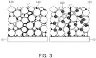
FIG. 3 is a schematic view conceptually illustrating lithium ion diffusion into an electrode mixture layer, depending on whether or not a second conductive material is added. - The following detailed description is provided to assist the reader in gaining a comprehensive understanding of the methods, apparatuses, and/or systems described herein. However, various changes, modifications, and equivalents of the methods, apparatuses, and/or systems described herein will be apparent to one of ordinary skill in the art. The sequences of operations described herein are merely examples, and are not limited to those set forth herein, but may be changed, as will be apparent to one of ordinary skill in the art, with the exception of operations necessarily occurring in a certain order. Also, descriptions of functions and constructions that would be well known to one of ordinary skill in the art may be omitted for increased clarity and conciseness.
- The terminology used herein describes particular embodiments only, and the present disclosure is not limited thereby. As used herein, the singular forms "a," "an," and "the" are intended to include the plural forms as well, unless the context clearly indicates otherwise. It will be further understood that the terms "including", "comprises," and/or "comprising" when used in this specification, specify the presence of stated features, integers, steps, operations, members, elements, and/or groups thereof, but do not preclude the presence or addition of one or more other features, integers, steps, operations, members, elements, and/or groups thereof.
- Throughout the specification, it will be understood that when an element, such as a layer, region or wafer (substrate), is referred to as being "on," "connected to," or "coupled to" another element, it may be directly "on," "connected to," or "coupled to" the other element or other elements intervening therebetween may be present. In contrast, when an element is referred to as being "directly on, " "directly connected to," or "directly coupled to" another element, there may be no elements or layers intervening therebetween. Like numerals refer to like elements throughout. As used herein, the term "and/or" includes any and all combinations of one or more of the associated listed items.
- The drawings may not be to scale, and the relative size, proportions, and depiction of elements in the drawings may be exaggerated for clarity, illustration, and convenience.
- Hereinafter, embodiments of the present disclosure will be described with reference to various embodiments. However, the embodiments of the present disclosure may be modified into various other forms, and the scope of the present disclosure is not limited to the embodiments described below.
- According to an embodiment, a multilayer electrode comprised of a plurality of electrode mixture layers, including conductive materials having different average particle diameters and porosity, and a lithium secondary battery including the same, are provided.
- In recent years, to increase a battery energy density and reduce manufacturing costs, the thickness of an electrode has increased and the density of an electrode mixture layer has increased. However, as the thickness and density of the electrode increase, the movement of electrons and the movement of lithium ions are restricted, resulting in a problem such as performance degradation in output characteristics and a high rate of a battery.
- Therefore, according to an embodiment of the present disclosure to prevent occurrence of a problem as described above, a multilayer electrode including a porous conductive material, which has an electric conductivity similar to that of a generally used conductive material and has a relatively large average particle diameter and pores in the conductive material itself, to be capable of facilitating movement of lithium ions, may be provided.
- According to an embodiment of the present disclosure, a multilayer electrode includes a
current collector 10, a firstelectrode mixture layer 110 formed on at least one surface of thecurrent collector 10, and a secondelectrode mixture layer 130 formed on the first electrode mixture layer. The first and secondelectrode mixture layers electrode mixture layer 130 is greater than the porosity of a conductive material contained in the firstelectrode mixture layer 110. - The conductive material is added to impart conductivity without causing chemical changes in a battery. However, in a case in which the conductive material content increases, the conductivity increases, but as the conductive material having a smaller average particle diameter and a lower density than those of an active material is present in a relatively large amount in the material mixture layer, the porosity of an electrode is decreased and movement distances of ions increases, based on the same mixture layer weight, a restriction on the movement of the lithium ions occurs, causing a problem such as deterioration in performance of output characteristics and a high rate of a battery.
- Accordingly, in an embodiment of the present disclosure, a multilayer electrode, including the first and second electrode mixture layers sequentially stacked on a current collector, is configured in such a manner that the porosity of a conductive material contained in the second electrode mixture layer is greater than the porosity of a conductive material contained in the first electrode mixture layer, and thus, movement of lithium ions may be smooth.
- In detail, the porosity of the conductive material contained in the first electrode mixture layer is 0 to 30%, and the porosity of the conductive material contained in the second electrode mixture layer may be 50 to 90%, in more detail, 60 to 80%. If the porosity of the conductive material contained in the second electrode mixture layer is less than 50%, the function thereof may be difficult to serve as a movement path of lithium ions. If the porosity of the conductive material contained in the second electrode mixture layer exceeds 90%, it is difficult to maintain the conductive material form, and thus, the conductive material may easily break during a calendeing process and the function thereof may also be difficult to serve as a movement path of lithium ions.
- The shape of the conductive material is not particularly limited, but may be spherical. For smooth movement of the lithium ions as described above, an average particle diameter of the conductive material included in the second electrode mixture layer may be greater than an average particle diameter of the conductive material contained in the first electrode mixture layer.
- In detail, an average particle diameter D50 of the conductive material contained in the first electrode mixture layer is 0.01 to 0.5 µm, and an average particle diameter of the conductive material contained in the second electrode mixture layer is 0.5 to 5 µm, in more detail, 1 to 3µm. If the average particle diameter D50 of the conductive material contained in the second electrode mixture layer is less than 0.5 µm, since the conductive material may only fill pores between active material particles, it may be difficult to sufficiently perform the role of relatively shortening the movement path of lithium ions. If the average particle diameter D50 of the conductive material contained in the second electrode mixture layer exceeds 0.5 µm, as a surface area of the conductive material decreases, electrical contact resistance between active material particles, as well as between active material particles and current collector particles, may increase.
- An average pore diameter of the conductive material contained in the second electrode mixture layer may be greater than an average pore diameter of the conductive material contained in the first electrode mixture layer. For example, the average pore diameter of the conductive material contained in the first electrode mixture layer may be 0 to 0.01 µm, and the average pore diameter of the conductive material contained in the second electrode mixture layer may be 0.01 to 0.5 µm, in detail, 0.05 to 0.3 µm. If the average pore diameter of the conductive material contained in the second electrode mixture layer is less than 0.01 um, the radius of the lithium ion diffusion path may be reduced, so that a diffusion rate of lithium ions through the pores of the conductive material is significantly reduced. If the average pore diameter of the conductive material contained in the second electrode mixture layer exceeds 0.5 µm, strength of a conductive material layer may be reduced and the conductive material layer may be easily cracked during a calendeing process.
- Examples of the conductive material contained in the first and second electrode mixture layers in an embodiment include carbon such as carbon black, acetylene black, furnace black, ketjen black, artificial graphite, natural graphite or the like, and a metal such as silver, aluminum, copper or the like. Further, as a material of the first and second electrode mixture layers, only one kind of conductive material having different porosity and different average particle diameters may be used, or two or more conductive materials may be used in which the porosity and an average particle diameter of a plurality of conductive materials in the second electrode mixture layer may be greater than the porosity and an average particle diameter of the conductive material contained in the first electrode mixture layer.
- In addition, the content of the conductive material contained in the second electrode mixture layer may be more than 0.5 wt% to less than 5 wt% of the total active material content of the electrode mixture layer. If the content of the conductive material contained in the second electrode mixture layer is 0.5 wt% or less, the formation of pores due to the conductive material in the electrode mixture layer is insufficient and the diffusion of lithium ions is difficult to improve. If the content of the conductive material contained in the second electrode mixture layer is 5 wt% or more, the formation of pores is sufficient, but contact between the active material and the conductive material is insufficient due to an increase in an average surface area of the conductive material in the electrode mixture layer, thereby lowering electric conductivity of the electrode mixture layer.
- On the other hand, a thickness of the second electrode mixture layer may be 20 to 80% of the total thickness of the electrode mixture layer. If the thickness of the second electrode mixture layer is less than 20%, the effect of diffusion of lithium ions into the electrode mixture layer is insignificant, even in a case in which pores are formed due to the second conductive material. If the thickness of the second electrode mixture layer is more than 80%, formation of pores in the electrode mixture layer may be sufficient, but electric conductivity of the electrode mixture layer may be lowered due to an increase in the average surface area of the conductive material in the electrode mixture layer.
- Further, according to an embodiment of the present disclosure, a multilayer electrode includes a current collector; a first electrode mixture layer formed on at least one surface of the current collector; and a second electrode mixture layer formed on the first electrode mixture layer. The first and second electrode mixture layers include a first conductive material and a second conductive material having a porosity higher than that of the first conductive material. In this case, a content of the second conductive material contained in the second electrode mixture layer is greater than a content of the second conductive material contained in the first electrode mixture layer. For example, in the first electrode mixture layer and the second electrode mixture layer, a conductive material having a relatively low porosity and a second conductive material having a relatively high porosity may be mixed with each other. In this case, the conductive material having a relatively great porosity may be contained in a relatively large amount in the second electrode mixture layer than in the first electrode mixture layer.
- The porosity of the first conductive material may be 0 to 30%, and the porosity of the second conductive material may be 50 to 90%, in detail, 60 to 80%. If the porosity of the second conductive material is less than 50%, the function thereof may be difficult to serve as a movement path of lithium ions. If the porosity of the second conductive material exceeds 90%, it is difficult to maintain the conductive material form, and thus, the conductive material may easily break during a calendeing process and the function thereof may also be difficult to serve as a movement path of lithium ions.
- For example, by including a relatively large amount of conductive material having a high porosity in the second electrode mixture layer, movement of lithium ions may be further smooth as described above.
- The shape of the first and second conductive materials is not particularly limited, but may be spherical. For smooth movement of lithium ions, an average particle diameter of the second conductive material may be greater than an average particle diameter of the first conductive material.
- In detail, the first conductive material may have an average particle diameter D50 of 0.01 to 0.5 µm, and the second conductive material may have an average particle diameter of 0.5 to 5 µm, in detail, 1 to 3 µm. If the average particle diameter D50 of the second conductive material is less than 0.5 µm, since the conductive material may only fill pores between active material particles, it may be difficult to sufficiently perform the role of relatively shortening the movement path of lithium ions. If the average particle diameter D50 of the second conductive material exceeds 5 µm, there may be a problem in which electrical contact resistance between active material particles, as well as between active material particles and current collector particles, may increase.
- The average pore diameter of the second conductive material may also be greater than the average pore diameter of the first conductive material. For example, the average pore diameter of the first conductive material may be 0 to 0.01 um, and the average pore diameter of the second conductive material may be 0.01 to 0.5 µm, in detail, 0.05 to 0.3 um. If the average pore diameter of the second conductive material is less than 0.01 µm, the radius of the lithium ion diffusion path may be reduced, such that a diffusion rate of lithium ions through pores of the conductive material is significantly reduced. If the average pore diameter of the second conductive material exceeds 0.5 µm, strength of a conductive material layer is lowered and may easily break during a calendeing process.
- In this case, since the second electrode mixture layer relatively far from the current collector includes a relatively large amount of the second conductive material having a relatively great average particle diameter and high porosity, lithium ions may be smoothly moved while maintaining electrical conductivity. Further, since the average particle diameter of the second conductive material is greater than that of the first conductive material, if the second conductive material is added in the same mass as that of the first conductive material due to the effect of reduction in a surface area of a conductive material, the function of the conductive material as a medium of connecting an active material having low conductivity to the current collector is insufficient. Thus, resistance of a battery may be increased even in a case in which the electrical contact resistance increases and consequently the diffusion resistance of the lithium ion decreases. Therefore, to facilitate the diffusion of lithium ions and prevent electrical contact resistance between an active material and a current collector from being reduced, the second conductive material is distributed more in the second electrode mixture layer than in the first electrode mixture layer, only reducing a bottleneck phenomenon in diffusion of lithium ions.
- The total contents of the conductive materials included in the first and second electrode mixture layers may be the same, and in the case in which the contents of conductive materials contained in respective layers are the same, since the porosity of the second conductive material contained in the second electrode mixture layer is greater than that of the first conductive material contained in the first electrode mixture layer, charging and discharging performance at the output and the high rate of the battery may be improved.
- The content of the second conductive material contained in the second electrode mixture layer may be more than 0.5 wt% to less than 5 wt% of the total active material content of the electrode mixture layer. If the content of the second conductive material is 0.5 wt% or less, the formation of pores due to the conductive material in the electrode mixture layer is insufficient and the diffusion of lithium ions is difficult to improve. If the content of the second conductive material is 5 wt% or more, formation of pores is sufficient, but there is a problem in which electric conductivity of the electrode mixture layer may be lowered due to insufficient contact between an active material and a conductive material by an increase in an average surface area of the conductive material in the electrode mixture layer.
- On the other hand, a thickness of the second electrode mixture layer may be 20 to 80% of the total thickness of the electrode mixture layer. If the thickness of the second electrode mixture layer is less than 20%, the effect of diffusion of lithium ions into the electrode mixture layer is insignificant even in a case in which pores are formed due to the second conductive material. If the thickness of the second electrode mixture layer is more than 80%, pores in the electrode mixture layer are sufficiently formed, but the electric conductivity of the electrode mixture layer may be lowered due to an increase in an average surface area of the conductive material in the electrode mixture layer.
- As a material of the current collector constituting the multilayer electrode according to an example, for example, stainless steel, aluminum, nickel, titanium, stainless steel surface-treated with sintered carbon, copper, carbon, nickel, titanium or silver, an aluminum-cadmium alloy, a nonconductive polymer surface-treated with a conductive material, and a conductive polymers, or the like may be used, but an example thereof is not limited thereto.
- The multilayer electrode according to an embodiment may be a cathode or an anode, and in the case of a cathode, the first and second electrode mixture layers may include a cathode active material and a binder. Examples of the cathode active material include a layered compound such as lithium cobalt oxide (LiCoO2), lithium nickel oxide (LiNiO2) or the like, a compound substituted with 1 or more transition metals, a compound represented by the formula Li1+xMn2-xO4 (x is 0 to 0.33), lithium manganese oxides such as LiMnO3, LiMn2O3, LiMnO2, or the like, lithium copper oxide (Li2CuO2) ; a vanadium oxide such as LiV3O8, LiFe3O4, V2O5, Cu2V2O7, or the like, a Ni-site type lithium nickel oxide represented by the formula LiNi1-xMxO2 (where M = Co, Mn, Al, Cu, Fe, Mg, B or Ga and x = 0.01 to 0.3) ; a lithium manganese composite oxide represented by the formula LiMn2-xMxO2 (where M = Co, Ni, Fe, Cr, Zn or Ta, and x = 0.01 to 0.1) or Li2Mn3MO8 (where M = Fe, Co, Ni, Cu or Zn), a lithium manganese composite oxide of a spinel structure represented by LiNixMn2-xO4, LiMn2O4 in which a portion of Li in the formula is substituted with an alkaline earth metal ion, disulfide compounds, Fe2 (MoO4)3, lithium nickel manganese cobalt composite oxide (NMC), and the like, without limitation, but the examples thereof are not limited thereto.
- For example, when the multilayer electrode is an anode, examples of an anode active material may include one or more carbon-based materials selected from crystalline artificial graphite, crystalline natural graphite, amorphous hard carbon, low crystalline soft carbon, carbon black, acetylene black, Ketjen black, super P, graphene and fibrous carbon, Si-based materials, a metal complex oxide such as LixFe2O3 (0=x≤=1), LixWO2 (0=x≤=1), SnxMe1-xMe'yOz (Me: Mn, Fe, Pb, Ge; Me': Al, B, P, Si, group 1, group 2, group 3 elements of the periodic table, halogen; 0<x=1; 1≤=y≤=3; 1≤=z≤=8), or the like, a lithium metal, a lithium alloy, a silicon-based alloy, a tin-based alloy, a metal oxide such as SiO, SiO2, SnO, SnO2, PbO, PbO2, Pb2O3, Pb3O4, Sb2O3, Sb2O4, Sb2O5, GeO, GeO2, Bi2O3, Bi2O4, and Bi2O5, or the like, a conductive polymer such as polyacetylene or the like, Li-Co-Ni-based materials, a titanium oxide, a lithium titanium oxide, and the like.
- On the other hand, a binder contained in the electrode mix layer to improve adhesion or the like is not particularly limited, but examples of the binder may include, for example, polyvinylidene fluoride (PVDF), polyvinyl alcohol, Carboxymethylcellulose (CMC), starch, hydroxypropylcellulose, regenerated cellulose, polyvinylpyrrolidone, tetrafluoroethylene, polyethylene, polypropylene, ethylene-propylene-diene terpolymer (EPDM), sulfonated EPDM, styrene-butylene rubber (SBR), fluorine rubber, or styrene monomer (SM), butadiene (BD), butyl acrylate (BA), mussel protein, polyolefin binder, silane binder, and the like.
- According to another embodiment, a lithium secondary battery including the multilayer electrode described above is provided. Thus, charging and discharging characteristics at the output and the high rate of a lithium secondary battery may be improved.
- Hereinafter, the present disclosure will be described in more detail with reference to example embodiments. The following examples are intended to further illustrate the present disclosure and are not intended to limit the present disclosure.
- A cathode active material (nickel cobalt manganese oxide), a first conductive material (trade name: XC-72) and a binder (polyvinylidene fluoride) were mixed to have a weight ratio of 95%, 2.5% and 2.5%, respectively, and were then mixed in an N-methylpyrrolidone (NMP) solvent to have the weight of a solid of about 65%, thereby preparing a first mixture layer slurry.
- A cathode active material (nickel cobalt manganese oxide), a first conductive material (trade name: XC-72), a second conductive material (trade name: LD2N, D50 = 3 µm, porosity = 75%) and a binder (polyvinylidene fluoride) were mixed to have a weight ratio of 95%, 1.5%, 1.0% and 2.5%, respectively, and were then mixed in an N-methylpyrrolidone (NMP) solvent to have the weight of a solid of about 65%, thereby preparing a second mixture layer slurry.
- The first cathode mixture layer slurry was applied to one surface of an aluminum foil (having a thickness of 12 µm) to a thickness of about 50 µm to form a first electrode mixture layer. Subsequently, the second cathode mixture layer slurry was applied to the first electrode mixture layer to a thickness of about 50 µm to form a second electrode mixture layer, followed by drying.
- Then, the first and second electrode mixture layers were calendeed to prepare a cathode having a final thickness of 65 µm.
- A cathode active material (nickel cobalt manganese oxide), a first conductive material (trade name: XC-72) and a binder (polyvinylidene fluoride) were mixed to have a weight ratio of 95%, 2.5% and 2.5% %, respectively, and were then mixed in an N-methylpyrrolidone (NMP) solvent to have the weight of a solid of about 65%, thereby preparing a first mixture layer slurry.
- A cathode active material (nickel cobalt manganese oxide), a first conductive material (trade name: XC-72), a second conductive material (trade name: LD2N, D50 = 3 µm, porosity = 75%) and a binder (polyvinylidene fluoride) were mixed to have a weight ratio of 95%, 0.5%, 2.0% and 2.5%, respectively, and were then mixed in an N-methylpyrrolidone (NMP) solvent to have the weight of a solid of about 65%, thereby preparing a second mixture layer slurry.
- The first cathode mixture layer slurry was applied to one surface of an aluminum foil (having a thickness of 12 µm) to a thickness of about 50 um to form a first electrode mixture layer. Subsequently, the second cathode mixture layer slurry was applied to the first electrode mixture layer to a thickness of about 50 µm to form a second electrode mixture layer, followed by drying.
- Then, the first and second electrode mixture layers were calendeed to prepare a cathode having a final thickness of 65 µm.
- A cathode active material (nickel cobalt manganese oxide), a first conductive material (trade name: XC-72) and a binder (polyvinylidene fluoride) were mixed to have a weight ratio of 95%, 2.5% and 2.5% %, respectively, and were then mixed in an N-methylpyrrolidone (NMP) solvent to have the weight of a solid of about 65%, thereby preparing a cathode slurry.
- The cathode slurry was applied to one surface of an aluminum foil (having a thickness of 12 um) to a thickness of about 100 µm to form an electrode mixture layer, followed by drying.
- Then, the first and second electrode mixture layers were calendeed to prepare a cathode having a final thickness of 65 µm.
- A cathode active material (nickel cobalt manganese oxide), a first conductive material (trade name: XC-72), a second conductive material (trade name: LD2N, D50 = 3 um, porosity = 75%) and a binder (polyvinylidene fluoride) were mixed to have a weight ratio of 95%, 2.0%, 0.5% and 2.5%, respectively, and were then mixed in an N-methylpyrrolidone (NMP) solvent to have the weight of a solid of about 65%, thereby preparing a cathode slurry.
- The cathode slurry was applied to one surface of an aluminum foil (having a thickness of 12 um) to a thickness of about 100 um to form an electrode mixture layer, followed by drying.
- Then, the first and second electrode mixture layers were calendeed to prepare a cathode having a final thickness of 65 µm.
- A cathode active material (nickel cobalt manganese oxide), a first conductive material (trade name: XC-72), a second conductive material (trade name: LD2N, D50 = 3 um, porosity = 75%) and a binder (polyvinylidene fluoride) were mixed to have a weight ratio of 95%, 1.5%, 1.0% and 2.5%, respectively, and were then mixed in an N-methylpyrrolidone (NMP) solvent to have the weight of a solid of about 65%, thereby preparing a cathode slurry.
- The cathode slurry was applied to one surface of an aluminum foil (having a thickness of 12 um) to a thickness of about 100 µm to form an electrode mixture layer, followed by drying.
- Then, the first and second electrode mixture layers were calendeed to prepare a cathode having a final thickness of 65 um.
- A cathode active material (nickel cobalt manganese oxide), a second conductive material (trade name: LD2N, D50 = 3 µm, porosity = 75%) and a binder (polyvinylidene fluoride) were mixed to have a weight ratio of 94.5%, 3% and 2.5%, respectively, and were then mixed in an N-methylpyrrolidone (NMP) solvent to have the weight of a solid of about 65%, thereby preparing a cathode slurry.
- The cathode slurry was applied to one surface of an aluminum foil (having a thickness of 12 um) to a thickness of about 100 um to form an electrode mixture layer, followed by drying.
- Then, the first and second electrode mixture layers were calendeed, but a final thickness thereof was not reduced to 70 µm or less, and a subsequent process for manufacturing a cathode was stopped.
- Contact resistance between a current collector and an active material was measured on cathode mixture layers prepared in Embodiment Examples 1 to 2 and Comparative Examples 1 to 3, and the results are illustrated in Table 1.
- The contact resistance was measured by cutting a calendeed electrode into the size of about 10 x 10 mm, placing the cut electrode on an electrode resistance meter (Hioki), applying a current of 1.0 V and a current of 0.1 mA thereto and then measuring interfacial resistance between the current collector and the active material.
- Lithium secondary batteries manufactured using the cathodes prepared in Embodiment Examples 1 to 2 and Comparative Examples 1 to 3 were measured for 1.5 C charge capacity and discharge capacity, and the results are illustrated in Table 1.
- The battery prepared using the anode was charged and discharged three times at 0.3 C before measuring 1.5 C charge capacity and discharge capacity.
- To measure 1.5C charge capacity, the battery completed in discharging was charged until the voltage reaches 4.2V at the constant current (CC) mode of 1.5C, and was then continuously charged until the current decreases to 0.5% of an initial value from 4.2V. In Table 1, the charged capacity was used as a value obtained by dividing the charged capacity in this process by the discharge capacity of the last cycle during the 0.3C charging and discharging that was previously performed.
- To measure the 1.5C discharge capacity, the battery completed in charging was discharged until the voltage reached 2.5V at a constant current (CC) mode of 1.5C. The discharge capacity in Table 1 was used as a value obtained by dividing the discharged capacity in this process by the discharge capacity of the last cycle during 0.3C charging and discharging.
[Table 1] Compara tive Example 1 Comparat ive Example 2 Comparati ve Example 3 Embodimen t Example 1 Embod iment Examp le 2 First electrode mixture layer First conductive material weight 2.5% 2.0% 1.5% 2.5% 2.5% Second conductive material weight 0% 0.5% 1.0% 0% 0% Second electrode mixture layer First conductive material weight 2.5% 2.0% 1.5% 1.5% 0.5% Second conductive material weight 0% 0.5% 1.0% 1.0% 2.0% Current collector-active material contact resistance 0.31 0.42 0.57 0.30 0.29 DC-IR 1.72 1.64 1.66 1.62 1.60 1.5C Charge capacity(/0.3C discharge capacity) 74.4% 69.9% 76.2% 75.8% 77.9% 1.5 C discharge capacity(/0.3C discharge capacity) 48.8% 44.6% 53.1% 55.1% 58.5% - Referring to Table 1, it can be confirmed that according to embodiments of the present disclosure, all the effects such as contact resistance, charge/discharge capacity and the like are improved.
- As set forth above, according to an embodiment, ion mobility to the inside of an electrode may be improved by including a conductive material having a relatively large average particle diameter and pores in the conductive material itself, and thus, output characteristics and relatively high rate charging and discharging performance of a lithium secondary battery may be improved.
- While this disclosure includes specific examples, it will be apparent to one of ordinary skill in the art that various changes in form and details may be made in these examples without departing from the spirit and scope of the claims and their equivalents. The examples described herein are to be considered in a descriptive sense only, and not for purposes of limitation. Descriptions of features or aspects in each example are to be considered as being applicable to similar features or aspects in other examples. Suitable results may be achieved if the described techniques are performed to have a different order, and/or if components in a described system, architecture, device, or circuit are combined in a different manner, and/or replaced or supplemented by other components or their equivalents. Therefore, the scope of the disclosure is defined not by the detailed description, but by the claims and their equivalents, and all variations within the scope of the claims and their equivalents are to be construed as being included in the disclosure.
Claims (15)
- A multilayer electrode comprising:a current collector;a first electrode mixture layer disposed on at least one surface of the current collector; anda second electrode mixture layer disposed on the first electrode mixture layer,wherein the first electrode mixture layer includes an electrode active material and a first conductive material and the second electrode mixture layer includes an electrode active material and a second conductive material, andthe average particle diameter of the first conductive material is 0.01 to 0.5 µm, and the average particle diameter of the second conductive material is 0.5 to 5 µm, and a porosity of the second conductive material is greater than a porosity of the second conductive material.
- The multilayer electrode of claim 1, wherein the porosity of the first conductive material is 0 to 30%, and the porosity of the second conductive material is 50 to 90%.
- The multilayer electrode of any one claim of claims 1 to 2, wherein a content of the first conductive material and the second conductive material is more than 0.5 wt% to less than 5 wt% of total the first and second electrode mixture layer.
- The multilayer electrode of any one claim of claims 1 to 3, wherein an average pore diameter of the first conductive material is 0 to 0.01 µm, and an average pore diameter of the second conductive material is 0.01 to 0.5 µm.
- The multilayer anode of any one claim of claims 1 to 4, wherein the first and second conductive materials are one or more selected from carbon black, acetylene black, furnace black, ketjen black, carbon nanotubes, artificial graphite, natural graphite, silver, aluminum and copper.
- The multilayer electrode of any one claim of claims 1 to 5, wherein a thickness of the second electrode mixture layer is 20 to 80% of a total thickness of the first and second electrode mixture layers.
- The multilayer electrode of any one claim of claims 1 to 6, wherein a content of the second conductive material is more than 0.5 wt% to less than 5 wt% of a total active material content of the first and second electrode mixture layers.
- A multilayer electrode comprising:a current collector;a first electrode mixture layer disposed on at least one surface of the current collector; anda second electrode mixture layer disposed on the first electrode mixture layer,wherein the first and second electrode mixture layers include a first conductive material and a second conductive material having a porosity greater than a porosity of the first conductive material, and a content of the second conductive material contained in the second electrode mixture layer is greater than a content of the second conductive material contained in the first electrode mixture layer.
- The multilayer electrode of claim 8, wherein the porosity of the first conductive material is 0 to 30%, and the porosity of the second conductive material is 50 to 90%.
- The multilayer electrode of any one claim of claims 8 to 9, wherein a content of the first conductive material and the second conductive material is more than 0.5 wt% to less than 5 wt% of total the first and second electrode mixture layer.
- The multilayer electrode of any one claim of claims 8 to 10, wherein an average pore diameter of the first conductive material is 0 to 0.01 µm, and an average pore diameter of the second conductive material is 0.01 to 0.5 µm.
- The multilayer anode of any one claim of claims 8 to 11, wherein the first and second conductive materials are selected from carbon black, acetylene black, furnace black, ketjen black, carbon nanotubes, artificial graphite, natural graphite, silver, aluminum and copper.
- The multilayer electrode of any one claim of claims 8 to 12, wherein a thickness of the second electrode mixture layer is 20 to 80% of a total thickness of the first and second electrode mixture layers.
- The multilayer electrode of any one claim of claims 8 to 13, wherein a content of the second conductive material contained in the second electrode mixture layer is more than 0.5 wt% to less than 5 wt% of a total active material content of the first and second electrode mixture layers.
- A lithium secondary battery comprising the multilayer electrode according to any one claim of claims 1 to 14.
Applications Claiming Priority (2)
| Application Number | Priority Date | Filing Date | Title |
|---|---|---|---|
| KR1020180109623A KR20200030852A (en) | 2018-09-13 | 2018-09-13 | Multi layer electrode and lithum secondary battery including the same |
| EP19196013.7A EP3624235B1 (en) | 2018-09-13 | 2019-09-06 | Multilayer electrode and lithium secondary battery including the same |
Related Parent Applications (2)
| Application Number | Title | Priority Date | Filing Date |
|---|---|---|---|
| EP19196013.7A Division EP3624235B1 (en) | 2018-09-13 | 2019-09-06 | Multilayer electrode and lithium secondary battery including the same |
| EP19196013.7A Division-Into EP3624235B1 (en) | 2018-09-13 | 2019-09-06 | Multilayer electrode and lithium secondary battery including the same |
Publications (1)
| Publication Number | Publication Date |
|---|---|
| EP4207341A1 true EP4207341A1 (en) | 2023-07-05 |
Family
ID=67875397
Family Applications (2)
| Application Number | Title | Priority Date | Filing Date |
|---|---|---|---|
| EP23154762.1A Pending EP4207341A1 (en) | 2018-09-13 | 2019-09-06 | Multilayer electrode and lithium secondary battery including the same |
| EP19196013.7A Active EP3624235B1 (en) | 2018-09-13 | 2019-09-06 | Multilayer electrode and lithium secondary battery including the same |
Family Applications After (1)
| Application Number | Title | Priority Date | Filing Date |
|---|---|---|---|
| EP19196013.7A Active EP3624235B1 (en) | 2018-09-13 | 2019-09-06 | Multilayer electrode and lithium secondary battery including the same |
Country Status (4)
| Country | Link |
|---|---|
| US (3) | US11557755B2 (en) |
| EP (2) | EP4207341A1 (en) |
| KR (1) | KR20200030852A (en) |
| CN (1) | CN110896145B (en) |
Families Citing this family (6)
| Publication number | Priority date | Publication date | Assignee | Title |
|---|---|---|---|---|
| KR20200030852A (en) * | 2018-09-13 | 2020-03-23 | 에스케이이노베이션 주식회사 | Multi layer electrode and lithum secondary battery including the same |
| CN116508178A (en) * | 2020-10-30 | 2023-07-28 | 松下知识产权经营株式会社 | Positive electrode for secondary battery and secondary battery |
| CN112599719A (en) * | 2020-12-14 | 2021-04-02 | 珠海冠宇电池股份有限公司 | Negative plate, preparation method of negative plate and battery |
| CN113097432B (en) * | 2021-03-30 | 2022-06-24 | 宁德新能源科技有限公司 | Electrochemical device and electronic device |
| CN116918091A (en) * | 2021-06-21 | 2023-10-20 | 株式会社Lg新能源 | Electrode for electrochemical device |
| CN116111045B (en) * | 2023-04-11 | 2023-12-19 | 宁德新能源科技有限公司 | Positive electrode plate, preparation method thereof, secondary battery and electronic device |
Citations (2)
| Publication number | Priority date | Publication date | Assignee | Title |
|---|---|---|---|---|
| EP2819221A1 (en) * | 2012-02-23 | 2014-12-31 | Toyota Jidosha Kabushiki Kaisha | Sealed nonaqueous electrolyte secondary battery |
| KR20170039976A (en) * | 2015-10-02 | 2017-04-12 | 주식회사 엘지화학 | Negative electrode and secondary battery comprising the same |
Family Cites Families (13)
| Publication number | Priority date | Publication date | Assignee | Title |
|---|---|---|---|---|
| US20050241137A1 (en) * | 2004-04-28 | 2005-11-03 | Tdk Corporation | Electrode, electrochemical device, and method of making electrode |
| US20110168550A1 (en) * | 2010-01-13 | 2011-07-14 | Applied Materials, Inc. | Graded electrode technologies for high energy lithium-ion batteries |
| WO2011109815A1 (en) * | 2010-03-05 | 2011-09-09 | A123 Systems, Inc. | Design and fabrication of electrodes with gradients |
| CN103650214B (en) * | 2011-07-12 | 2016-04-20 | 应用材料公司 | Manufacture the method for the porosity change of lithium ion cell electrode film |
| DE112011105960T5 (en) * | 2011-12-14 | 2014-09-25 | Toyota Jidosha Kabushiki Kaisha | A non-aqueous electrolyte secondary battery and a method of manufacturing a negative electrode for a secondary battery |
| KR101623724B1 (en) * | 2013-07-29 | 2016-05-24 | 주식회사 엘지화학 | Anode Mixture for Secondary Battery Having Improved Structural Safety and Secondary Battery Having the Same |
| KR101839754B1 (en) | 2015-04-02 | 2018-03-19 | 주식회사 엘지화학 | Multi-Layered Electrode of Different Porosity and Method for Preparation of the Same |
| KR101812625B1 (en) | 2015-04-14 | 2018-01-30 | 주식회사 엘지화학 | Multilayer Electrode for Secondary Battery Having Different Volume of Conductive Materials and Preparation Method Thereof |
| KR101810185B1 (en) * | 2015-04-29 | 2017-12-19 | 주식회사 엘지화학 | An electrode for an electrochemical device and a method for manufacturing the same |
| KR102094483B1 (en) * | 2015-11-12 | 2020-03-30 | 주식회사 엘지화학 | Positive Electrode Mix for Secondary Battery Comprising Conductive Materials of Different Shapes |
| JP6447608B2 (en) * | 2016-10-19 | 2019-01-09 | トヨタ自動車株式会社 | Method for producing non-aqueous electrolyte secondary battery |
| US10424784B2 (en) * | 2016-10-28 | 2019-09-24 | GM Global Technology Operations LLC | Negative electrode including silicon nanoparticles having a carbon coating thereon |
| KR20200030852A (en) * | 2018-09-13 | 2020-03-23 | 에스케이이노베이션 주식회사 | Multi layer electrode and lithum secondary battery including the same |
-
2018
- 2018-09-13 KR KR1020180109623A patent/KR20200030852A/en active IP Right Grant
-
2019
- 2019-09-06 EP EP23154762.1A patent/EP4207341A1/en active Pending
- 2019-09-06 EP EP19196013.7A patent/EP3624235B1/en active Active
- 2019-09-12 CN CN201910864864.0A patent/CN110896145B/en active Active
- 2019-09-16 US US16/572,180 patent/US11557755B2/en active Active
-
2021
- 2021-11-23 US US17/534,330 patent/US20220085360A1/en active Pending
-
2022
- 2022-12-20 US US18/085,238 patent/US11870064B2/en active Active
Patent Citations (2)
| Publication number | Priority date | Publication date | Assignee | Title |
|---|---|---|---|---|
| EP2819221A1 (en) * | 2012-02-23 | 2014-12-31 | Toyota Jidosha Kabushiki Kaisha | Sealed nonaqueous electrolyte secondary battery |
| KR20170039976A (en) * | 2015-10-02 | 2017-04-12 | 주식회사 엘지화학 | Negative electrode and secondary battery comprising the same |
Non-Patent Citations (1)
| Title |
|---|
| "A Basic Guide to Particle Characterization", MALVERN INSTRUMENTS WORLDWIDE - WHITE PAPER, 2 May 2012 (2012-05-02), pages 1 - 26, XP055089322, Retrieved from the Internet <URL:http://golik.co.il/Data/ABasicGuidtoParticleCharacterization(2)_1962085150.pdf> [retrieved on 20181106] * |
Also Published As
| Publication number | Publication date |
|---|---|
| US20230120558A1 (en) | 2023-04-20 |
| KR20200030852A (en) | 2020-03-23 |
| US20200185707A1 (en) | 2020-06-11 |
| EP3624235A1 (en) | 2020-03-18 |
| CN110896145B (en) | 2024-04-09 |
| US11870064B2 (en) | 2024-01-09 |
| CN110896145A (en) | 2020-03-20 |
| EP3624235B1 (en) | 2023-03-15 |
| US20220085360A1 (en) | 2022-03-17 |
| US11557755B2 (en) | 2023-01-17 |
Similar Documents
| Publication | Publication Date | Title |
|---|---|---|
| EP3624235B1 (en) | Multilayer electrode and lithium secondary battery including the same | |
| JP2016042490A (en) | Cathode active material, electrode, and secondary battery improved in lithium ion mobility and battery capacity | |
| EP3660956A1 (en) | Negative electrode for lithium secondary battery, and lithium secondary battery comprising same | |
| US11094921B2 (en) | Electrode for electrochemical device and method for manufacturing the same | |
| EP3863084B1 (en) | Negative electrode and secondary battery including same | |
| KR20210007273A (en) | Composite anode active material, and Anode and Lithium secondary battery comprising the same | |
| KR20210143980A (en) | Secondary battery | |
| CN110679014A (en) | Method for predicting manufacturability of electrode slurry and selecting electrode binder | |
| CN110890525A (en) | Positive active material for lithium secondary battery and lithium secondary battery including the same | |
| CN110462885B (en) | Bar-shaped electrode for cylindrical jelly roll and lithium secondary battery comprising same | |
| KR20200017218A (en) | Electrode for lithium secondary battery and lithium secondary battery including the same | |
| CN113206254A (en) | Cathode material, cathode including the same, and lithium battery including the cathode | |
| KR20200028258A (en) | Anode for secondary battery and Secondary battery including the same | |
| US10777816B2 (en) | Method for preparing an electrode for a secondary battery | |
| EP4213229A1 (en) | Anode for secondary battery, method for preparing the same, and secondary battery comprising said anode | |
| EP4037010A1 (en) | Electrode for secondary battery, and secondary battery comprising same | |
| US20220285744A1 (en) | Battery system, and method of using the same and battery pack including the same | |
| KR102567400B1 (en) | Secondary battery | |
| KR102328430B1 (en) | Anode comprising porous cellulose and secondary battery having the same | |
| KR102518386B1 (en) | Positive electrode and secondary battery comprising the same | |
| US20220059844A1 (en) | Electrode for Secondary Battery and Method for Preparing the Same | |
| US20220320483A1 (en) | Anode for all-solid-state battery containing no active material and all-solid-state battery including the same | |
| KR102630852B1 (en) | Electrode Assembly Comprising Separator Having Conductive Layer and Battery Cell Comprising the Same | |
| US20220069420A1 (en) | All-solid secondary battery | |
| EP4024537A1 (en) | Current collector comprising primer coating layer having improved adhesive strength, and manufacturing method for same |
Legal Events
| Date | Code | Title | Description |
|---|---|---|---|
| PUAI | Public reference made under article 153(3) epc to a published international application that has entered the european phase |
Free format text: ORIGINAL CODE: 0009012 |
|
| STAA | Information on the status of an ep patent application or granted ep patent |
Free format text: STATUS: THE APPLICATION HAS BEEN PUBLISHED |
|
| AC | Divisional application: reference to earlier application |
Ref document number: 3624235 Country of ref document: EP Kind code of ref document: P |
|
| AK | Designated contracting states |
Kind code of ref document: A1 Designated state(s): AL AT BE BG CH CY CZ DE DK EE ES FI FR GB GR HR HU IE IS IT LI LT LU LV MC MK MT NL NO PL PT RO RS SE SI SK SM TR |
|
| STAA | Information on the status of an ep patent application or granted ep patent |
Free format text: STATUS: REQUEST FOR EXAMINATION WAS MADE |
|
| 17P | Request for examination filed |
Effective date: 20240102 |
|
| RBV | Designated contracting states (corrected) |
Designated state(s): AL AT BE BG CH CY CZ DE DK EE ES FI FR GB GR HR HU IE IS IT LI LT LU LV MC MK MT NL NO PL PT RO RS SE SI SK SM TR |