EP4206621A1 - Ladenwaage - Google Patents
Ladenwaage Download PDFInfo
- Publication number
- EP4206621A1 EP4206621A1 EP21218423.8A EP21218423A EP4206621A1 EP 4206621 A1 EP4206621 A1 EP 4206621A1 EP 21218423 A EP21218423 A EP 21218423A EP 4206621 A1 EP4206621 A1 EP 4206621A1
- Authority
- EP
- European Patent Office
- Prior art keywords
- scales
- housing
- diffuser
- attached
- led
- Prior art date
- Legal status (The legal status is an assumption and is not a legal conclusion. Google has not performed a legal analysis and makes no representation as to the accuracy of the status listed.)
- Granted
Links
Images

Classifications
-
- G—PHYSICS
- G01—MEASURING; TESTING
- G01G—WEIGHING
- G01G21/00—Details of weighing apparatus
- G01G21/28—Frames, Housings
- G01G21/283—Details related to a user interface
-
- G—PHYSICS
- G01—MEASURING; TESTING
- G01G—WEIGHING
- G01G21/00—Details of weighing apparatus
- G01G21/28—Frames, Housings
Definitions
- the present invention relates to a scale, in particular a retail scale, with a weighing module.
- the weighing module includes a housing in which a load cell is accommodated.
- the load cell includes a fixed section, a deformation section, and a movable section.
- the fixed section is connected to the housing and the moveable section supports a cross beam with a load plate.
- the deformation section has a strain gauge for measuring a weight acting on the load plate.
- Such scales are well known to those skilled in the art.
- these scales include an operator display for interacting with the scale, for example to display a weight or to indicate malfunctions.
- the operator has to navigate through different menu levels to get specific information about the status of the scale. This is often time-consuming and not very intuitive for the operator.
- a scale in particular a shop scale, is proposed.
- the scale includes a weighing module.
- the weighing module includes a housing in which a load cell is housed.
- the load cell includes a fixed section, a deformation section, and a movable section.
- the fixed section is connected to the housing.
- the moving one Section carries a load cross with a load plate.
- the deformation section has a strain gauge for measuring a weight acting on the load plate.
- the housing is designed in one piece and is trough-shaped. On the outer wall of the one-piece housing, a light strip is attached to the housing essentially all the way around.
- the scales include a control unit with a status machine that maps at least one technical status of the scales, with the control unit controlling the luminous strip on the basis of the status of the status machine.
- the technical state represented by the state machine is a paper supply in a printer.
- the technical state that is mapped by the state machine is a difference from a target weight, which is formed by the weight determined by the load cell and the target weight.
- the technical status that is represented by the status machine is an outdated software version that has to be updated with updates.
- the technical state represented by the state machine is a speed of various weight detection steps or processing steps entered via an operator display.
- the technical state represented by the state machine is that an operator has correctly identified himself at the scale via the operator display.
- the person skilled in the art understands a one-piece and trough-shaped housing to mean a form of housing that resembles a trough. She has a square or rectangular Base area, the corners can be rounded.
- the housing has a base body which, in one embodiment, is made of cast metal and can therefore also have complex shapes, in particular openings and inner walls. The length and width of the housing are significantly greater than its height.
- the housing includes a base panel with side walls integrally formed on the base panel.
- the housing is open at the top and with a free space inside to accommodate different modules such as the load cell, electronic modules and others inside the housing. In one embodiment, the interior of the housing is covered at the top with a cover.
- the term one-piece and trough-shaped also includes a housing that has partitions for different rooms or stabilizing struts inside. Furthermore, this also includes a housing whose base plate is stepped in some places, so that there is a free space below the base plate of the housing at these points of the housing when the base body is placed on a flat surface. This free space is used, for example, for attaching plugs underneath the housing.
- the housing is also to be understood as one-piece and trough-shaped if there are through openings at various points in the, in particular stepped, base plate or side walls, for example for the attachment of sockets, the passage of cables or the assembly of supports and other elements the scales.
- the term trough-shaped is therefore only to be regarded as descriptive of the basic appearance of the housing.
- the light strip runs around the housing once, in particular the light strip runs once around the housing in the upper area of its side walls, it being possible for there to be a small distance between the start and end of the light strip in relation to the length of the light strip.
- the scales include a load plate that is placed on the load cross. The outer edges of the load plate lead over the cross and down over the top edge of the case so that the load plate floats like a lid on top of the case.
- the light strip is located at the top of the side walls of the housing but below the edges of the load plate.
- the light strip is attached to the upper edge of the housing in such a way that it is covered by the overhanging edges of the load plate. In this case, the light from the light strip shines diffusely from under the downward-pointing edges of the load plate.
- the light strip consists of a flexible carrier.
- the LED lamps are arranged on the flexible carrier.
- the carrier comprises one to ten LED light sources per cm of length.
- electrical lines for controlling the LED lighting means are integrated in the flexible carrier material of the lighting strip.
- the LED light sources generate light in the wavelength range from 230 nm to 500 nm.
- the carrier with the LED light sources is coated with phosphor.
- the light strip is coated with phosphor on the side on which the LED light sources are attached. Phosphor converts the blue or ultraviolet light from the LED bulbs into white light.
- each of the LED bulbs is or has been phosphor coated individually and separately, but that the LED bulbs are first mounted on the substrate and then the whole side of the substrate is phosphor coated.
- the density of the LED lamps per length of the light strip can be significantly increased and the result is a very homogeneous lighting effect.
- the illumination by the light from the LED lamps is approx. 170° in relation to the level of the light strip, which means that the light can also be perceived from very acute angles.
- the flexible carrier comprises first, second and third LED lighting means.
- the first LED lamps generate light in a wavelength range of 450 nm to 500 nm.
- the second LED lamps generate light in a wavelength range of 500 nm to 570 nm.
- the third LED illuminants generate light in a wavelength range of 610 nm to 760 nm.
- the first, second and third LED lighting means are arranged in regular arrangements on the carrier.
- the first LED light sources form a first group of LED light sources.
- the second LED lighting means form a second group of LED lighting means.
- the third LED lighting means form a third group of LED lighting means.
- the LED lamps in a group are controlled together by the control unit.
- the light strip is coated with silicone on the side on which the LED light sources are attached. Silicone is translucent. At the same time, a diffuse effect is created, so that the light from the individual LED lamps is scattered somewhat. In this way, superimposed colors are created from the three groups of LED lamps, which are perceptible to the human eye as blue, green and red, so that almost the entire RGB color space is available.
- the flexible carrier has a layer of adhesive material on the side opposite the LED lighting means. In one embodiment, it is a layer of thermally conductive adhesive material.
- the light strip is attached to the housing with the adhesive material, in particular glued on. The heat generated by the LED lighting means is given off to the housing via the layer of adhesive material, in particular via the thermally conductive adhesive material.
- the adhesive material adheres to a surface made of uncoated and/or coated cast metal, so that the housing can be coated or uncoated at the point to which the light strip is glued.
- the light strip is electrically connected to the control unit.
- the luminous strip is controlled by the control unit with a DC voltage in the range from 6° volts to 36° volts, in particular 12° volts or 24° volts.
- the housing comprises a cutout or a one-sided cutout, which is attached circumferentially in the upper housing area on the outside of the housing, into which the light strip is glued.
- a recess is to be understood as meaning a depression in the housing wall in the form of a groove.
- a one-sided recess means an edge that is present, for example, in a sloping housing wall. The edge forms a depression, the rear end of which is a vertical plane for receiving the light strip.
- the scale includes a diffuser that is attached to the outside of the housing and covers the recess.
- the diffuser ensures that the light from the LED light sources is scattered so that it is no longer evident that the light sources are discrete, but instead give the impression of an extended, homogeneous light source.
- the diffuser ensures that the light strip appears equally bright from every viewing angle. The diffuser enhances the effect of the phosphor or silicone.
- the diffuser consists of a translucent material.
- the translucent material is a translucent polycarbonate.
- the diffuser comprises a structure on its outside.
- the structuring makes the diffuser opaque from the outside towards the housing.
- the diffuser is translucent from the housing side to the outside.
- the diffuser is designed as a ring.
- the ring has the dimensions of the housing in the area of the recess.
- the ring is positively attached to the housing over the recess.
- the ring is attached with a latching mechanism.
- the diffuser covers the recess.
- the diffuser is glued or screwed to the housing.
- the distance between the LED lighting means and the inside of the diffuser is less than 3° mm. In one embodiment, the distance between the LED lighting means and the inside of the diffuser is less than 1° mm.
- the scale comprises a weighing module with a housing 18 in which a load cell is accommodated.
- the load cell carries a load cross, which in turn carries a load plate 11.
- the load plate 11 has a depending edge which extends beyond the upper edge of the housing 18.
- a stand 15 is fastened to the weighing module and carries a printer 12 with a label output 16 .
- the stand 15 also carries an operator display 13, which is designed as a touch screen and a customer display 14 opposite the operator display 13.
- the weighing module rests on four feet 17 attached to its corners.
- a light strip 19 is attached to the outer edge of the housing 18, which is controlled by a control unit depending on the technical condition of the scale.
- the scale comprises a weighing module with a housing 28 in which a load cell is accommodated.
- the load cell carries a load cross which in turn carries a load plate 21 .
- the load plate 21 has a depending edge which extends beyond the upper edge of the housing 28.
- the weighing module rests on a frame 25 which carries a printer 22 with a label dispenser 26 .
- the frame 25 also carries an operator display 23, which is designed as a touchscreen, and a customer display 24 opposite the operator display 23.
- a light strip 29 is attached to the outer edge of the housing 28, which is controlled by a control unit depending on the technical condition of the scale .
- the housing 18, 28 is a cast metal housing and can take on complex shapes.
- a load cell 30 is screwed to a base 35 with screws 34.
- the load cell 30 comprises a fixed section 31 screwed to the housing 18, 28, a deformation section 32 and a movable section 33 on which a load cross 39 with a fastening 38 is attached.
- the load cross 39 carries the load plate 11, 21 of the scale, with rubber buffers 40 being attached between the load cross 39 and the load plate 11, 21.
- the load plate 11,21 includes a bend 50 at its edges so that the load plate 11,21 projects laterally downwardly over the upper edges of the housing 18,28.
- the measured deformation is determined with an evaluation unit 37 and converted into a weight value of the product.
- the interior of the housing 18, 28, in which the load cell 30 and also a control unit 51 and possibly other components of the scale such as the power pack and the like are located, is covered with a cover 41.
- the housing 18, 28 consists of a base plate and four upstanding side walls.
- the housing is made of cast metal and is therefore formed in one piece. The transition between the base plate and side walls is beveled.
- a recess 44 is provided in the upper region of the side walls, so that a vertical outer wall 47 is set back somewhat on the side walls of the housing 18, 28.
- the carrier 42 of the light strip 19, 29 is glued to this vertical outer wall 47.
- the carrier 42 is made of flexible material and can therefore also be guided around the corners of the housing 18, 28 in the recess 44.
- flexible means that the carrier 42 can be bent at least perpendicularly to the plane in which the carrier 42 runs, but not necessarily also in the plane of the carrier 42 itself.
- the LED illuminants 43 can be attached in the longitudinal direction of the carrier 42 with a density of up to ten LED illuminants 43 per cm.
- Carrier 42 and LED lighting means 43 are covered on the side of the LED lighting means with a protective layer 48 made of silicone or phosphorus.
- the protective layer 48 is not only applied to the LED illuminants 43 themselves before they are mounted on the carrier 42, but is applied after the LED illuminants 43 have been mounted on the carrier 42 over the carrier 42 and the LED illuminants 42. In this way, a higher density of the LED illuminants 43 on the carrier 42 can be achieved and the beam angle for homogeneous light of each LED illuminant 43 increases to about 170°.
- a protective layer 48 made of silicone is applied if the LED illuminants 43 generate light in the wavelength range of 450 nm to 500 nm, 500 nm to 570 nm or 610 nm to 760 nm and the different LED illuminants 43 in regular arrangements are arranged on the carrier 42. As a result, the luminous strip 19, 29 can be made to light up in RGB colors via the control unit 51.
- a protective layer 48 of phosphor is applied when the LED light sources 43 emit light in the wavelength range from 230 nm to 500 nm (ultraviolet to blue light). The protective layer 48 made of phosphor makes this light visible to the operator as white light.
- the recess 44 with carrier 42, LED lighting means 43 and protective layer 48 is covered by a diffuser 49.
- the diffuser 49 provides mechanical protection for the luminous strip 19, 29 and at the same time breaks up the light, so that the luminous strip 19, 29 acts like a homogeneous light source.
- the diffuser 49 can be structured on its outer surface, that is to say the surface can be machined.
- the effect that the light strip 19, 29 acts like a homogeneous light source is caused by the high density of LED light sources 43 and by the common protective layer 48 made of silicone or phosphor on the LED light sources 43 and by the diffuser 49 and the outside Structuring of the diffuser 49 reinforced or completed.
- the diffuser 49 rests against surfaces 45, 46 of the housing 18, 28 above and below the recess 44 and is glued to these surfaces 45, 46, latched thereto with a latching connection or screwed.
- the diffuser 49 is an annular component which is slid over the housing 18,28 from below and fits positively onto the side walls of the housing 18,28.
- the diffuser 49 is made from a translucent material, in particular from translucent polycarbonate.
- the control unit 51 includes a state machine 52, which maps at least one technical state of the scale.
- the Control unit controls the light strip 19, 29 based on the state of the state machine 52.
- the technical status that is mapped by the status machine can be a supply of paper in a printer, a difference from a target weight that is formed by the weight determined by the load cell and the target weight, an outdated software version that needs to be updated through updates, a speed of various weight recording steps or processing steps entered via an operator display or that an operator has correctly identified himself on the scale via the operator display.
- the light strip can be controlled, for example, in different colors (red, yellow, green) for an RGB light strip or as glowing or flashing for a monochromatic lightweight tape.
- DSP digital signal processor
- ASIC application specific integrated circuit
- FPGA field programmable gate array
- ROM read only memory
- RAM random access memory
Landscapes
- Physics & Mathematics (AREA)
- General Physics & Mathematics (AREA)
- Engineering & Computer Science (AREA)
- Human Computer Interaction (AREA)
- Illuminated Signs And Luminous Advertising (AREA)
- Fastening Of Light Sources Or Lamp Holders (AREA)
Abstract
Description
- Die vorliegende Erfindung betrifft eine Waage, insbesondere eine Ladenwaage, mit einem Wägemodul. Das Wägemodul umfasst ein Gehäuse, in dem eine Wägezelle untergebracht ist. Die Wägezelle umfasst einen festen Abschnitt, einen Verformungsabschnitt und einen beweglichen Abschnitt. Der feste Abschnitt ist mit dem Gehäuse verbunden und der bewegliche Abschnitt trägt ein Lastkreuz mit einer Lastplatte. Der Verformungsabschnitt weist einen Dehnungsmesstreifen zur Messung eines auf die Lastplatte wirkenden Gewichts auf.
- Derartige Waagen sind dem Fachmann gut bekannt. Diese Waagen umfassen in aller Regel ein Bedienerdisplay zur Interaktion mit der Waage, zum Beispiel zum Anzeigen eines Gewichts oder zum Anzeigen von Fehlfunktionen. Dabei muss der Bediener durch verschiedene Menüebenen navigieren, um bestimmte Informationen über den Zustand der Waage zu erhalten. Dies ist für den Bediener oft aufwändig und wenig intuitiv.
- Aufgabe der Erfindung ist es, eine einfache Vorrichtung zu schaffen, die den Bediener über den Zustand der Waage in Kenntnis setzt und ihm die Interaktion mit der Waage erleichtert.
- Diese Aufgabe wird durch eine Waage mit den Merkmalen des Anspruchs 1 gelöst.
- Erfindungsgemäß wird eine Waage, insbesondere eine Ladenwaage vorgeschlagen. Die Waage umfasst ein Wägemodul. Das Wägemodul umfasst ein Gehäuse, in dem eine Wägezelle untergebracht ist. Die Wägezelle umfasst einen festen Abschnitt, einen Verformungsabschnitt und einen beweglichen Abschnitt. Der feste Abschnitt ist mit dem Gehäuse verbunden. Der bewegliche Abschnitt trägt ein Lastkreuz mit einer Lastplatte. Der Verformungsabschnitt weist einen Dehnungsmesstreifen zur Messung eines auf die Lastplatte wirkenden Gewichts auf. Das Gehäuse ist einstückig und wannenförmig ausgebildet. An der Außenwand des einstückigen Gehäuses ist ein Leuchtband im Wesentlichen umlaufend am Gehäuse angebracht. Im Wesentlichen umlaufend in diesem Zusammenhang meint, dass das Leuchtband drei Seiten und einen großen Teil der vierten Seite des Gehäuses umläuft, jedoch dass der Anfang und das Ende des Leuchtbandes nicht verbunden oder zusammentreffen müssen. Ein Abstand zwischen Anfang und Ende des Leuchtbandes, auf der Seite, auf der sich Anfang und Ende begegnen, ist damit ebenfalls gemeint. Die Waage umfasst eine Steuereinheit mit einer Zustandsmaschine, die mindestens einen technischen Zustand der Waage abbildet, wobei die Steuereinheit das Leuchtband aufgrund des Zustands der Zustandsmaschine ansteuert. In einer Ausführungsform ist der technische Zustand, der durch die Zustandsmaschine abgebildet wird, ein Papiervorrat in einem Drucker. In einer Ausführungsform ist der technische Zustand, der durch die Zustandsmaschine abgebildet wird, eine Differenz zu einem Sollgewicht, die durch das durch die Wägezelle ermittelte Gewicht und das Sollgewicht gebildet wird. In einer Ausführungsform ist der technische Zustand, der durch die Zustandsmaschine abgebildet wird, ein veralteter Softwarestand, der durch Updates aktualisiert werden muss. In einer Ausführungsform ist der technische Zustand, der durch die Zustandsmaschine abgebildet wird, eine Geschwindigkeit verschiedener Gewichtserfassungsschritte oder über ein Bedienerdisplay eingegebener Bearbeitungsschritte. In einer Ausführungsform ist der technische Zustand, der durch die Zustandsmaschine abgebildet wird, dass sich ein Bediener korrekt an der Waage über das Bedienerdisplay identifiziert hat.
- Der Fachmann versteht unter einem einstückig und wannenförmig ausgebildeten Gehäuse eine Form eines Gehäuses, die einer Wanne ähnelt. Sie hat eine quadratische oder rechteckige Grundfläche, wobei die Ecken abgerundet sein können. Das Gehäuse hat einen Grundkörper, der in einer Ausführungsform aus einem Metallguss hergestellt ist und somit auch komplexe Formen, insbesondere Öffnungen und innere Wandungen aufweisen kann. Die Länge und die Breite des Gehäuses sind wesentlich größer als dessen Höhe. Das Gehäuse umfasst eine Bodenplatte mit seitlichen Wänden, die einstückig an der Bodenplatte ausgebildet sind. Das Gehäuse ist oben offen und mit einem Freiraum im Inneren, um unterschiedliche Module, wie die Wägezelle, elektronische Module und Anderes im Inneren des Gehäuses aufzunehmen. In einer Ausführungsform ist der Innenbereich des Gehäuses oben mit einer Abdeckung abgedeckt. Unter den Begriff einstückig und wannenförmig fällt auch ein Gehäuse, das im Inneren Trennwände für verschiedene Räume oder Stabilisierungsstreben hat. Des Weiteren fällt auch ein Gehäuse darunter, dessen Bodenplatte an einigen Stellen stufenförmig ausgebildet ist, so dass an diesen Stellen des Gehäuses unterhalb der Bodenplatte des Gehäuses ein Freiraum entsteht, wenn der Grundkörper auf einer ebenen Fläche abgesetzt wird. Dieser Freiraum dient zum Beispiel für das Anbringen von Steckern unterhalb des Gehäuses. Das Gehäuse ist auch dann als einstückig und wannenförmig zu verstehen, wenn an verschiedenen Stellen in der, insbesondere abgestuften, Bodenplatte oder seitlichen Wänden Durchgangsöffnungen vorhanden sind, zum Beispiel für das Anbringen von Steckerbuchsen, das Durchführen von Kabeln oder die Montage von Trägern und anderen Elementen der Waage. Der Begriff wannenförmig ist deswegen nur als beschreibend für das grundsätzliche Erscheinungsbild des Gehäuses anzusehen.
- In einer Ausführungsform umläuft das Leuchtband das Gehäuse einmal, insbesondere umläuft das Leuchtband das Gehäuse im oberen Bereich seiner Seitenwände einmal, wobei zwischen Anfang und Ende des Leuchtbandes ein, im Verhältnis zur Länge des Leuchtbandes, kleiner Abstand sein kann. Dabei umfasst die Waage eine Lastplatte, die auf dem Lastkreuz abgelegt ist. Dabei führen die äußeren Ränder der Lastplatte über das Lastkreuz und über die Oberkante des Gehäuses nach unten, so dass die Lastplatte wie ein Deckel auf der Oberseite des Gehäuses schwebt. In einer Ausführungsform befindet sich das Leuchtband im oberen Bereich der Seitenwände des Gehäuses, jedoch unterhalb der Ränder der Lastplatte. In einer Ausführungsform ist das Leuchtband am oberen Rand des Gehäuses derart angebracht, dass es von den überstehenden Rändern der Lastplatte verdeckt wird. In diesem Fall leuchtet das Licht des Leuchtbandes diffus unter den nach unten stehenden Rändern der Lastplatte hervor.
- In einer Ausführungsform besteht das Leuchtband aus einem flexiblen Träger. Auf dem flexiblen Träger sind die LED-Leuchtmittel angeordnet. In einer Ausführungsform umfasst der Träger eine bis zehn LED-Leuchtmittel pro cm Länge.
- In einer Ausführungsform sind in dem flexiblen Trägermaterial des Leuchtbandes elektrische Leitungen für die Ansteuerung der LED-Leuchtmittel integriert.
- In einer Ausführungsform erzeugen die LED-Leuchtmittel Licht im Wellenlängenbereich von 230 nm bis 500 nm. Der Träger mit den LED-Leuchtmitteln ist mit Phosphor überzogen. Insbesondere ist das Leuchtband auf der Seite, auf der die LED-Leuchtmittel angebracht sind, mit Phosphor überzogen. Phosphor wandelt das blaue oder ultraviolette Licht der LED-Leuchtmittel in weißes Licht.
- Es ist insbesondere zu beachten, dass nicht jedes der LED-Leuchtmittel einzeln und separat mit Phosphor überzogen ist bzw. wurde, sondern dass die LED-Leuchtmittel zuerst auf dem Träger montiert werden und dann die ganze Seite des Trägers mit Phosphor überzogen wird. So kann die Dichte der LED-Leuchtmittel pro Länge des Leuchtbandes deutlich erhöht werden und es kommt zu einem sehr homogenen Leuchteffekt. Dies führt auch dazu, dass die Ausleuchtung durch das Licht der LED-Leuchtmittel im Bezug zur Ebene des Leuchtbandes ca. 170° beträgt, das heißt, das Licht ist auch aus sehr spitzen Winkeln wahrnehmbar.
- In einer Ausführungsform umfasst der flexible Träger erste, zweite und dritte LED-Leuchtmittel. Die ersten LED-Leuchtmittel erzeugen Licht in einem Wellenlängenbereich von 450°nm bis 500°nm. Die zweiten LED-Leuchtmittel erzeugen Licht in einem Wellenlängenbereich von 500°nm bis 570°nm. Die dritten LED-Leuchtmittel erzeugen Licht in einem Wellenlängenbereich 610°nm bis 760°nm. Die ersten, zweiten und dritten LED-Leuchtmittel sind in regelmäßigen Anordnungen auf dem Träger angeordnet. Die ersten LED-Leuchtmittel bilden eine erste Gruppe von LED-Leuchtmitteln. Die zweiten LED-Leuchtmittel bilden eine zweite Gruppe von LED-Leuchtmitteln. Die dritten LED-Leuchtmittel bilden eine dritte Gruppe von LED-Leuchtmitteln. Die LED-Leuchtmittel einer Gruppe werden durch die Steuereinheit jeweils gemeinsam angesteuert. In einer Ausführungsform ist das Leuchtband auf der Seite, auf der die LED-Leuchtmittel angebracht sind, mit Silikon überzogen. Silikon ist lichtdurchlässig. Gleichzeitig entsteht ein diffuser Effekt, so dass das Licht der einzelnen LED-Leuchtmittel etwas gestreut wird. So entstehen aus den drei Gruppen von LED-Leuchtmitteln, die für das menschliche Auge als blau, grün und rot wahrnehmbar sind, überlagerte Farben, so dass annähernd der gesamte RGB Farbraum zur Verfügung steht.
- In einer Ausführungsform weist der flexible Träger auf der den LED-Leuchtmitteln gegenüberliegenden Seite eine Schicht aus Klebematerial auf. In einer Ausführungsform handelt es sich um eine Schicht aus wärmeleitendem Klebematerial. Das Leuchtband ist mit dem Klebematerial am Gehäuse angebracht, insbesondere angeklebt. Die durch die LED-Leuchtmittel entstehende Hitze wird über die Schicht aus Klebematerial, insbesondere über das wärmeleitende Klebematerial, an das Gehäuse abgegeben.
- Das Klebematerial haftet dabei auf einer Fläche aus unbeschichtetem und/oder beschichtetem Metallguss, sodass das Gehäuse an der Stelle, an der das Leuchtband angeklebt wird, beschichtet oder unbeschichtet sein kann.
- In einer Ausführungsform ist das Leuchtband mit der Steuereinheit elektrisch verbunden. Das Leuchtband wird von der Steuereinheit mit einer Gleichspannung im Bereich von 6°Volt bis 36°Volt, insbesondere 12°Volt oder 24°Volt, angesteuert.
- In einer Ausführungsform umfasst das Gehäuse eine Aussparung oder eine einseitige Aussparung, die im oberen Gehäusebereich an der Außenseite des Gehäuses umlaufend angebracht ist, in die das Leuchtband eingeklebt ist. Unter Aussparung ist dabei eine Vertiefung in der Gehäusewand zu verstehen in der Form einer Rille. Eine einseitige Aussparung meint eine Kante, die zum Beispiel in einer schräg verlaufenden Gehäusewand vorhanden ist. Die Kante bildet eine Vertiefung, deren hinteres Ende zur Aufnahme des Leuchtbandes eine vertikale Ebene ist.
- In einer Ausführungsform umfasst die Waage einen Diffusor, der außen am Gehäuse angebracht ist und die Aussparung abdeckt. Der Diffusor sorgt für eine Streuung des Lichtes der LED-Leuchtquellen, sodass nicht mehr zu erkennen ist, dass es sich um diskrete Lichtquellen handelt, sondern dass der Eindruck entsteht, es würde sich um eine ausgedehnte homogene Lichtquelle handeln. Außerdem sorgt der Diffusor dafür, dass das Leuchtband aus jedem Betrachtungswinkel gleich hell wirkt. Der Diffusor verstärkt den Effekt des Phosphors beziehungsweise des Silikons.
- In einer Ausführungsform besteht der Diffusor aus einem transluzenten Material. In einer Ausführungsform handelt es sich bei dem transluzenten Material um ein transluzentes Polycarbonat.
- In einer Ausführungsform umfasst der Diffusor auf seiner Außenseite eine Strukturierung. Die Strukturierung macht den Diffusor von der Außenseite in Richtung Gehäuse blickdicht. Hingegen ist der Diffusor von der Gehäuseseite nach außen transluzent.
- In einer Ausführungsform ist der Diffusor als Ring ausgebildet. Der Ring hat die Abmessungen des Gehäuses im Bereich der Aussparung. Der Ring ist formschlüssig an dem Gehäuse über der Aussparung angebracht. Insbesondere ist der Ring mit einem Rastmechanismus angebracht. In einer Ausführungsform deckt der Diffusor die Aussparung ab. In einer Ausführungsform ist der Diffusor mit dem Gehäuse verklebt oder verschraubt.
- In einer Ausführungsform ist die Distanz zwischen den LED-Leuchtmitteln und der Innenseite des Diffusors kleiner 3° mm. In einer Ausführungsform ist die Distanz zwischen den LED-Leuchtmitteln und der Innenseite des Diffusors kleiner 1° mm.
- Einige Ausführungsformen der Erfindung sind in den Zeichnungen beispielhaft gezeigt und nachfolgend beschrieben. Es zeigen, jeweils in schematischer Darstellung:
- Fig. 1
- Eine erfindungsgemäße Ladenwage in einer ersten Ausführungsform,
- Fig. 2
- Eine erfindungsgemäße Ladenwage in einer zweiten Ausführungsform,
- Fig. 3
- Einen Ausschnitt einer erfindungsgemäßen Ladenwaage.
-
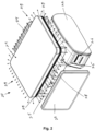
Fig. 1 zeigt eine erfindungsgemäße Waage 10 nach einer ersten Ausführungsform. Die Waage umfasst einen Wägemodul mit einem Gehäuse 18, in dem eine Wägezelle untergerbacht ist. Die Wägezelle trägt ein Lastkreuz, das seinerseits eine Lastplatte 11 trägt. Die Lastplatte 11 hat einen nach unten stehenden Rand, der über die obere Kante des Gehäuses 18 ragt. Am Wägemodul ist ein Stativ 15 befestigt, das einen Drucker 12 mit einer Etikettenausgabe 16 trägt. Das Stativ 15 trägt ferner ein Bedienerdisplay 13, das als Touchscreen ausgebildet ist, und ein dem Bedienerdisplay 13 gegenüberliegendes Kundendisplay 14. Das Wägemodul ruht auf vier in seinen Ecken angebrachten Füßen 17. An äußeren Rand des Gehäuses 18 ist umlaufend ein Leuchtband 19 angebracht, das von einer Steuereinheit in Abhängigkeit eines technischen Zustands der Waage angesteuert wird. -
Fig. 2 zeigt eine erfindungsgemäße Waage 20 nach einer zweiten Ausführungsform. Die Waage umfasst einen Wägemodul mit einem Gehäuse 28, in dem eine Wägezelle untergerbacht ist. Die Wägezelle trägt ein Lastkreuz, das seinerseits eine Lastplatte 21 trägt. Die Lastplatte 21 hat einen nach unten stehenden Rand, der über die obere Kante des Gehäuses 28 ragt. Das Wägemodul ruht auf einem Gestell 25, das einen Drucker 22 mit einer Etikettenausgabe 26 trägt. Das Gestell 25 trägt ferner ein Bedienerdisplay 23, das als Touchscreen ausgebildet ist, und ein dem Bedienerdisplay 23 gegenüberliegendes Kundendisplay 24. An äußeren Rand des Gehäuses 28 ist umlaufend ein Leuchtband 29 angebracht, das von einer Steuereinheit in Abhängigkeit eines technischen Zustands der Waage angesteuert wird. -
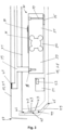
Fig. 3 zeigt einen Schnitt durch das Gehäuse 18, 28 einer Waage 10, 20. Das Gehäuse 18, 28 ist ein Metallgussgehäuse und kann komplexe Formen annehmen. Im Inneren des Gehäuses 18, 28 ist auf einem Sockel 35 eine Wägezelle 30 mit Schrauben 34 verschraubt. Die Wägezelle 30 umfasst einen mit dem Gehäuse 18, 28 verschraubten festen Abschnitt 31, einen Verformungsabschnitt 32 und einen beweglichen Abschnitt 33, auf dem ein Lastkreuz 39 mit einer Befestigung 38 angebracht ist. Das Lastkreuz 39 trägt die Lastplatte 11, 21 der Waage, wobei zwischen Lastkreuz 39 und Lastplatte 11, 21 Gummipuffer 40 angebracht sind. Die Lastplatte 11, 21 umfasst an ihren Rändern eine Biegung 50, so dass die Lastplatte 11, 21 seitlich nach unten über die oberen Ränder des Gehäuses 18, 28 ragt. Die Gewichtskraft eines Produkts auf der Lastplatte 11, 21 und auch die Gewichtskraft von Lastkreuz 39 und Lastplatte 11, 21 selbst wirken so auf den beweglichen Abschnitt 33 der Wägezelle 30. Dies führt zu einer mechanischen Verformung des Verformungsabschnitts 32, welche über auf dem Verformungsabschnitt 32 angebrachte Dehnungsmesstreifen 36 gemessen wird. Die gemessene Verformung wird mit einer Auswerteeinheit 37 bestimmt und in einen Gewichtswert des Produkts umgerechnet. Der Innenraum des Gehäuses 18, 28, in dem sich die Wägezelle 30 und auch eine Steuereinheit 51 und ggf. weitere Komponenten der Waage wie Netzteil und ähnliches befinden, ist mit einer Abdeckung 41 abgedeckt. - Das Gehäuse 18, 28 besteht aus einer Bodenplatte und vier nach oben ragenden Seitenwänden. Das Gehäuse ist aus Metallguss und somit einstückig ausgebildet. Der Übergang zwischen Bodenplatte und Seitenwänden ist angeschrägt. Im oberen Bereich der Seitenwände ist eine Aussparung 44 angebracht, so dass eine vertikal stehende Außenwand 47 an den Seitenwänden des Gehäuses 18, 28 etwas zurückversetzt ist. An dieser vertikal stehenden Außenwand 47 ist der Träger 42 des Leuchtbandes 19, 29 festgeklebt. Der Träger 42 ist aus flexiblem Material gebildet und kann somit auch um die Ecken des Gehäuses 18, 28 in der Aussparung 44 geführt werden. Flexibel meint in diesem Zusammenhang, dass der Träger 42 zumindest senkrecht zur Ebene, in der der Träger 42 verläuft, verbogen werden kann, nicht gezwungenermaßen auch in der Ebene des Trägers 42 selbst. Auf dem Träger 42 sind LED-Leuchtmittel 43 abgebracht. Die LED-Leuchtmittel 43 können in Längsrichtung des Trägers 42 mit einer Dichte von bis zu zehn LED-Leuchtmittel 43 pro cm angebracht sein. Träger 42 und LED-Leuchtmittel 43 sind auf der Seite der LED-Leuchtmittel mit einer Schutzschicht 48 aus Silikon oder Phosphor abgedeckt. Dabei ist die Schutzschicht 48 nicht nur auf den LED-Leuchtmitteln 43 selbst vor deren Montage auf dem Träger 42 angebracht, sondern wird nach der Montage der LED-Leuchtmittel 43 auf dem Träger 42 über den Trägers 42 und die LED-Leuchtmittel 42 angebracht. So kann eine höhere Dichte der LED-Leuchtmittel 43 auf dem Träger 42 erreicht werden und der Abstrahlwinkel für homogenes Licht jedes LED-Leuchtmittels 43 erhöht sich auf ca. 170°. Eine Schutzschicht 48 aus Silikon wird aufgetragen, wenn die LED-Leuchtmittel 43 Licht im Wellenlängenbereich von 450°nm bis 500°nm, 500°nm bis 570°nm beziehungsweise 610°nm bis 760° nm erzeugen und die unterschiedlichen LED-Leuchtmittel 43 in regelmäßigen Anordnungen auf dem Träger 42 angeordnet sind. Hierdurch kann das Leuchtband 19, 29 in RGB Farben über die Steuereinheit 51 zum Leuchten gebracht werden. Eine Schutzschicht 48 aus Phosphor wird aufgetragen, wenn die LED-Leuchtmittel 43 Licht im Wellenlängenbereich von 230 nm bis 500 nm (ultraviolettes bis blaues Licht) abgeben. Durch die Schutzschicht 48 aus Phosphor wird dieses Licht für den Bediener als weißes Licht sichtbar.
- Die Aussparung 44 mit Träger 42, LED-Leuchtmitteln 43 und Schutzschicht 48 ist durch einen Diffusor 49 abgedeckt. Der Diffusor 49 bietet einen mechanischen Schutz des Leuchtbandes 19, 29 und bricht das Licht gleichzeitig, so dass das Leuchtband 19, 29 wie eine homogene Lichtquelle wirkt. Dazu kann der Diffusor 49 auf seiner äußeren Fläche strukturiert, das heißt oberflächenbearbeitet sein. Der Effekt, dass das Leuchtband 19, 29 wie eine homogene Lichtquelle wirkt, wird durch die hohe Dichte an LED-Leuchtmitteln 43 und durch die gemeinsame Schutzschicht 48 aus Silikon oder Phosphor auf den LED-Leuchtmitteln 43 hervorgerufen und durch den Diffusor 49 und die außenseitige Strukturierung des Diffusors 49 verstärkt bzw. vervollständigt. Der Diffusor 49 liegt an Flächen 45, 46 des Gehäuses 18, 28 oberhalb und unterhalb der Aussparung 44 an und ist an diese Flächen 45, 46 geklebt, mit einer Rastverbindung daran verrastet oder verschraubt. Der Diffusor 49 ist ein ringförmiges Bauteil, das von unten über das Gehäuse 18,28 geschoben wird und formschlüssig auf die Seitenwände des Gehäuses 18, 28 passt. Der Diffusor 49 ist aus transluzentem Material, insbesondere aus transluzentem Polycarbonat, hergestellt.
- Die Steuereinheit 51 umfasst eine Zustandsmaschine 52, die mindestens einen technischen Zustand der Waage abbildet. Die Steuereinheit steuert das Leuchtband 19, 29 aufgrund des Zustandes der Zustandsmaschine 52.
- Der technische Zustand, der durch die Zustandsmaschine abgebildet wird, kann ein Papiervorrat in einem Drucker sein, eine Differenz zu einem Sollgewicht, die durch das durch die Wägezelle ermittelte Gewicht und das Sollgewicht gebildet wird, ein veralteter Softwarestand, der durch Updates aktualisiert werden muss, eine Geschwindigkeit verschiedener Gewichtserfassungsschritte oder über ein Bedienerdisplay eingegebener Bearbeitungsschritte oder dass sich ein Bediener korrekt an der Waage über das Bedienerdisplay identifiziert hat. Je nachdem, in welchem Zustand sich die Zustandsmaschine aufgrund verschiedener Eingangsparameter von Wägezelle, Sensoren oder der Waagensteuerung befindet, kann eine Ansteuerung des Leuchtbandes zum Beispiel in verschiedenen Farben (rot, gelb, grün) bei einem RGB Leuchtband oder als leuchtend bzw. blinkend bei einem monochromen Leichtband erfolgen.
- Die Funktionen verschiedener in den Zeichnungen gezeigter Elemente, inklusive der Funktionsblöcke, können durch dezidierte Hardware oder durch generische Hardware, die in der Lage ist, Software auszuführen, im Zusammenhang mit der entsprechenden Software, realisiert werden. Falls die Funktionen mittels eines Prozessors zur Verfügung gestellt werden, können sie durch einen einzigen dezidierten Prozessor, einen einzigen geteilten Prozessor oder mehrere generische Prozessoren, die wiederum geteilt sein können, zur Verfügung gestellt werden. Die Funktionen können, ohne Einschränkung, durch einen digital signal processor (DSP), Netzwerk Prozessor, application specific integrated circuit (ASIC), field programmable gate array (FPGA), read only memory (ROM) mit gespeicherter Software, random access memory (RAM), und nichtflüchtige Speicher zur Verfügung gestellt werden.
Claims (15)
- Waage (10, 20), insbesondere Ladenwaage, mit einem Wägemodul, wobei das Wägemodul ein Gehäuse (18, 28) umfasst, in dem eine Wägezelle (30) untergebracht ist, wobei die Wägezelle (30) einen festen Abschnitt (31), einen Verformungsabschnitt (32) und einen beweglichen Abschnitt (33) umfasst, wobei der feste Abschnitt (31) mit dem Gehäuse (18, 28) verbunden ist und der bewegliche Abschnitt (33) ein Lastkreuz (39) mit einer Lastplatte (11, 21) trägt, wobei der Verformungsabschnitt (32) einen Dehnungsmesstreifen (36) zur Messung eines auf die Lastplatte (11, 21) wirkenden Gewichts aufweist, dadurch gekennzeichnet, dass das Gehäuse (18, 28) einstückig und wannenförmig ausgebildet ist, wobei an der Außenwand (47) des Gehäuses ein Leuchtband (19, 29) angebracht ist, das im Wesentlichen umlaufend am Gehäuse (18, 28) angebracht ist, und dass die Waage eine Steuereinheit (51) umfasst, die eine Zustandsmaschine (52) umfasst, die mindestens einen technischen Zustand der Waage abbildet, wobei die Steuereinheit (51) das Leuchtband (19, 29) aufgrund des Zustands der Zustandsmaschine (52) ansteuert.
- Waage, insbesondere Ladenwaage, nach Anspruch 1, wobei das Leuchtband aus einem flexiblen Träger (42,) besteht, auf dem die LED-Leuchtmittel (43) angeordnet sind, wobei der Träger (42) insbesondere eine bis zehn LED-Leuchtmittel (43) pro cm Länge umfasst.
- Waage, insbesondere Ladenwaage, nach Anspruch 2, dadurch gekennzeichnet, dass in dem flexiblen Träger (42) des Leuchtbandes (19, 29) elektrische Leitungen für die Ansteuerung der LED-Leuchtmittel (43) integriert sind.
- Waage, insbesondere Ladenwaage, nach Anspruch 2 oder 3, dadurch gekennzeichnet, dass die LED-Leuchtmittel (43) Licht im Wellenlängenbereich von 230 nm bis 500 nm erzeugen und insbesondere mit Phosphor überzogen sind, wobei insbesondere das Leuchtband (19, 29) auf der Seite, auf der die LED-Leuchtmittel (43) angebracht sind, mit Phosphor überzogen ist.
- Waage, insbesondere Ladenwaage, nach Anspruch 2 oder 3, dadurch gekennzeichnet, dass der flexible Träger (42) erste, zweite und dritte LED-Leuchtmittel (43) umfasst, die Licht im Wellenlängenbereich von 450°nm bis 500°nm, 500°nm bis 570°nm beziehungsweise 610°nm bis 760°nm erzeugen und die ersten, zweiten und dritten LED-Leuchtmittel (43) in regelmäßigen Anordnungen auf dem Träger angeordnet sind, wobei die ersten, zweiten und dritten LED-Leuchtmittel (43) jeweils als Gruppe gemeinsam angesteuert werden, und wobei insbesondere das Leuchtband auf der Seite, auf der die LED-Leuchtmittel (43) angebracht sind, mit Silikon überzogen ist.
- Waage, insbesondere Ladenwaage, nach einem der Ansprüche Anspruch 1 bis 5, dadurch gekennzeichnet, dass der flexible Träger (42) auf der den LED-Leuchtmitteln (43) gegenüberliegenden Seite eine Schicht aus Klebematerial, insbesondere eine Schicht aus wärmeleitendem Klebematerial aufweist, wobei das Leuchtband mit dem Klebematerial am Gehäuse angebracht, insbesondere angeklebt ist.
- Waage, insbesondere Ladenwaage, nach Anspruch 6, dadurch gekennzeichnet, dass das Gehäuse (18, 28) aus einem Metallguss hergestellt ist und das Klebematerial auf einer Fläche aus unbeschichtetem und/oder beschichtetem Metallguss haftet.
- Waage, insbesondere Ladenwaage, nach einem der Ansprüche 1 bis 7, dadurch gekennzeichnet, dass das Leuchtband (19, 29) mit der Steuereinheit (51) elektrisch verbunden ist und das Leuchtband von der Steuereinheit mit einer Gleichspannung im Bereich von 6°Volt bis 36°Volt, insbesondere 12°Volt oder 24°Volt angesteuert wird.
- Waage, insbesondere Ladenwaage, nach einem der Ansprüche 1 bis 8, dadurch gekennzeichnet, dass das Gehäuse eine Aussparung oder eine einseitige Aussparung (44) umfasst, die im oberen Gehäusebereich (18, 28) an der Außenseite (47) des Gehäuses (18, 28) umlaufend angebracht ist, in die das Leuchtband (19, 29) eingeklebt ist.
- Waage, insbesondere Ladenwaage, nach Anspruch 9, dadurch gekennzeichnet, dass die Waage einen Diffusor (49) umfasst, der außen am Gehäuse angebracht ist und die Aussparung (44) abdeckt.
- Waage, insbesondere Ladenwaage, nach Anspruch 10, dadurch gekennzeichnet, dass der Diffusor (49) aus einem transluzenten Material, insbesondere aus transluzentem Polycarbonat, besteht.
- Waage, insbesondere Ladenwaage, nach Anspruch 11, dadurch gekennzeichnet, dass der Diffusor (49) auf seiner Außenseite eine Strukturierung umfasst, die ihn von der Außenseite in Richtung Gehäuse blickdicht macht und der Diffusor von der Gehäuseseite nach außen transluzent ist.
- Waage, insbesondere Ladenwaage, nach einem der Ansprüche 10 bis 12, dadurch gekennzeichnet, dass der Diffusor (49) als Ring ausgebildet ist, der die Abmessungen des Gehäuses (18, 28) im Bereich der Aussparung (44) hat und formschlüssig an dem Gehäuse über der Aussparung (44) angebracht ist und insbesondere mit einem Rastmechanismus angebracht ist.
- Waage, insbesondere Ladenwaage, nach einem der Ansprüche 10 bis 13, dadurch gekennzeichnet, dass der Diffusor (49) die Aussparung abdeckt und mit dem Gehäuse verklebt oder verschraubt ist.
- Waage, insbesondere Ladenwaage, nach einem der Ansprüche 10 bis 14, dadurch gekennzeichnet, dass die Distanz zwischen den LED-Leuchtmitteln (43) und der Innenseite des Diffusors kleiner 3° mm, insbesondere kleiner 1° mm ist.
Priority Applications (2)
| Application Number | Priority Date | Filing Date | Title |
|---|---|---|---|
| EP21218423.8A EP4206621B1 (de) | 2021-12-31 | 2021-12-31 | Ladenwaage |
| US18/083,599 US12449297B2 (en) | 2021-12-31 | 2022-12-19 | Retail weighing scale |
Applications Claiming Priority (1)
| Application Number | Priority Date | Filing Date | Title |
|---|---|---|---|
| EP21218423.8A EP4206621B1 (de) | 2021-12-31 | 2021-12-31 | Ladenwaage |
Publications (2)
| Publication Number | Publication Date |
|---|---|
| EP4206621A1 true EP4206621A1 (de) | 2023-07-05 |
| EP4206621B1 EP4206621B1 (de) | 2024-03-13 |
Family
ID=79230585
Family Applications (1)
| Application Number | Title | Priority Date | Filing Date |
|---|---|---|---|
| EP21218423.8A Active EP4206621B1 (de) | 2021-12-31 | 2021-12-31 | Ladenwaage |
Country Status (2)
| Country | Link |
|---|---|
| US (1) | US12449297B2 (de) |
| EP (1) | EP4206621B1 (de) |
Families Citing this family (2)
| Publication number | Priority date | Publication date | Assignee | Title |
|---|---|---|---|---|
| ES2993719T3 (en) * | 2022-06-01 | 2025-01-07 | Bizerba Se & Co Kg | Load scales |
| USD1138812S1 (en) * | 2024-06-10 | 2026-08-04 | Illinois Tool Works Inc. | Scale |
Citations (3)
| Publication number | Priority date | Publication date | Assignee | Title |
|---|---|---|---|---|
| DE102009049567A1 (de) * | 2009-10-15 | 2011-04-21 | Leifheit Ag | Personenwaage |
| DE202011050040U1 (de) * | 2011-05-05 | 2011-07-14 | Beurer Gmbh | Waage |
| DE102011083562A1 (de) * | 2011-09-27 | 2013-03-28 | BSH Bosch und Siemens Hausgeräte GmbH | Waage |
Family Cites Families (11)
| Publication number | Priority date | Publication date | Assignee | Title |
|---|---|---|---|---|
| US7163311B2 (en) * | 2004-10-22 | 2007-01-16 | Kramer James F | Foodware having visual sensory stimulating or sensing means |
| US20070186515A1 (en) * | 2006-02-16 | 2007-08-16 | Ruetten Roger M | System for monitoring flexible container usage |
| JP5687924B2 (ja) * | 2011-02-25 | 2015-03-25 | 株式会社イシダ | 計量印字装置 |
| WO2016180656A1 (en) * | 2015-05-08 | 2016-11-17 | Philips Lighting Holding B.V. | Led light strip and method for manufacturing the same |
| US20160356640A1 (en) * | 2015-06-05 | 2016-12-08 | Joseph M. Freeman | Receptacle Scale for Measuring a Weight of a Receptacle |
| EP3367871B1 (de) * | 2015-10-28 | 2021-03-24 | Acera LLC | Elliptische optische linse für hochleistungs-led |
| WO2017222394A1 (en) * | 2016-06-20 | 2017-12-28 | Anago Limited | Cutting force analyser |
| US20190249854A1 (en) * | 2018-02-11 | 2019-08-15 | Giotto's Ind.Inc. | Rail Structure And Rail Lighting Structure |
| US11678753B2 (en) * | 2019-10-06 | 2023-06-20 | James F. Kramer | Foodware system including a dining plate having sensing component, and information and entertainment display |
| US20210262851A1 (en) * | 2020-02-26 | 2021-08-26 | Illinois Tool Works Inc. | Weighing system and method |
| JP7504730B2 (ja) * | 2020-09-04 | 2024-06-24 | 東芝テック株式会社 | 決済装置 |
-
2021
- 2021-12-31 EP EP21218423.8A patent/EP4206621B1/de active Active
-
2022
- 2022-12-19 US US18/083,599 patent/US12449297B2/en active Active
Patent Citations (3)
| Publication number | Priority date | Publication date | Assignee | Title |
|---|---|---|---|---|
| DE102009049567A1 (de) * | 2009-10-15 | 2011-04-21 | Leifheit Ag | Personenwaage |
| DE202011050040U1 (de) * | 2011-05-05 | 2011-07-14 | Beurer Gmbh | Waage |
| DE102011083562A1 (de) * | 2011-09-27 | 2013-03-28 | BSH Bosch und Siemens Hausgeräte GmbH | Waage |
Also Published As
| Publication number | Publication date |
|---|---|
| US20230213374A1 (en) | 2023-07-06 |
| US12449297B2 (en) | 2025-10-21 |
| EP4206621B1 (de) | 2024-03-13 |
Similar Documents
| Publication | Publication Date | Title |
|---|---|---|
| EP0046842B1 (de) | Vorrichtung zur gleichmässigen Ausleuchtung von Schriftfeldern | |
| DE112011103598B4 (de) | Fahrzeugeinrichtung | |
| EP4206621B1 (de) | Ladenwaage | |
| DE112014003496B4 (de) | Anzeigevorrichtung | |
| DE112010006040T5 (de) | Flüssigkristallanzeigenmodul und einteilige Rückplatte davon | |
| DE3625767A1 (de) | Lichtdiffusionsvorrichtung mit rueckstrahler | |
| DE102017115274A1 (de) | Beleuchtungsvorrichtung | |
| EP4206622B1 (de) | Ladenwaage | |
| DE102010050331B4 (de) | Vorrichtung zum Wiegen von Menschen | |
| DE112012001840T5 (de) | LED-Beleuchtungseinheit | |
| DE102013022119A1 (de) | Leuchte | |
| DE3302156C2 (de) | Beleuchtungseinrichtung für eine transmissiv betreibbare passive Anzeige | |
| DE112023002273T5 (de) | Hintergrundbeleuchtungsstruktur und wandmontierter Zentralkontrollbildschirm | |
| EP1010159B1 (de) | Leuchtreklame, insbesondere leuchtbuchstabe | |
| DE9405535U1 (de) | Display-Modul | |
| DE102014010310B3 (de) | Beleuchtetes Zeigerinstrument für ein Kraftfahrzeug | |
| EP4488974B1 (de) | Verkaufsvorrichtung | |
| EP2761261B1 (de) | Waage mit strahlungsemittierenden bauelement | |
| DE29719393U1 (de) | Lichtaussendendes Kennzeichnungsschild | |
| DE202004001911U1 (de) | LED-Anzeige mit Lichtschirm-Wirkung | |
| DE10015467A1 (de) | Vereinfachtes Kombiinstrument | |
| DE1623705C (de) | Anzeigevorrichtung fur Nullinstrumente | |
| DE102025123561A1 (de) | Matrix-LED-Hintergrundbeleuchtung für eine LCD-Anzeigevorrichtung, Anordnung, LCD-Anzeigevorrichtung sowie Verfahren zum Betreiben einer Matrix-LED-Hintergrundbeleuchtung | |
| DE102013105278A1 (de) | Innendekorelement für einen Innenraum eines Kraftfahrzeugs | |
| EP3862732A1 (de) | Waage |
Legal Events
| Date | Code | Title | Description |
|---|---|---|---|
| PUAI | Public reference made under article 153(3) epc to a published international application that has entered the european phase |
Free format text: ORIGINAL CODE: 0009012 |
|
| STAA | Information on the status of an ep patent application or granted ep patent |
Free format text: STATUS: THE APPLICATION HAS BEEN PUBLISHED |
|
| AK | Designated contracting states |
Kind code of ref document: A1 Designated state(s): AL AT BE BG CH CY CZ DE DK EE ES FI FR GB GR HR HU IE IS IT LI LT LU LV MC MK MT NL NO PL PT RO RS SE SI SK SM TR |
|
| STAA | Information on the status of an ep patent application or granted ep patent |
Free format text: STATUS: REQUEST FOR EXAMINATION WAS MADE |
|
| 17P | Request for examination filed |
Effective date: 20230727 |
|
| RBV | Designated contracting states (corrected) |
Designated state(s): AL AT BE BG CH CY CZ DE DK EE ES FI FR GB GR HR HU IE IS IT LI LT LU LV MC MK MT NL NO PL PT RO RS SE SI SK SM TR |
|
| GRAP | Despatch of communication of intention to grant a patent |
Free format text: ORIGINAL CODE: EPIDOSNIGR1 |
|
| STAA | Information on the status of an ep patent application or granted ep patent |
Free format text: STATUS: GRANT OF PATENT IS INTENDED |
|
| GRAS | Grant fee paid |
Free format text: ORIGINAL CODE: EPIDOSNIGR3 |
|
| RIN1 | Information on inventor provided before grant (corrected) |
Inventor name: SAUTER, DANIEL Inventor name: BUHL, STEFFEN |
|
| INTG | Intention to grant announced |
Effective date: 20231222 |
|
| GRAA | (expected) grant |
Free format text: ORIGINAL CODE: 0009210 |
|
| STAA | Information on the status of an ep patent application or granted ep patent |
Free format text: STATUS: THE PATENT HAS BEEN GRANTED |
|
| AK | Designated contracting states |
Kind code of ref document: B1 Designated state(s): AL AT BE BG CH CY CZ DE DK EE ES FI FR GB GR HR HU IE IS IT LI LT LU LV MC MK MT NL NO PL PT RO RS SE SI SK SM TR |
|
| REG | Reference to a national code |
Ref country code: GB Ref legal event code: FG4D Free format text: NOT ENGLISH |
|
| REG | Reference to a national code |
Ref country code: CH Ref legal event code: EP |
|
| REG | Reference to a national code |
Ref country code: DE Ref legal event code: R096 Ref document number: 502021002963 Country of ref document: DE |
|
| REG | Reference to a national code |
Ref country code: IE Ref legal event code: FG4D Free format text: LANGUAGE OF EP DOCUMENT: GERMAN |
|
| PG25 | Lapsed in a contracting state [announced via postgrant information from national office to epo] |
Ref country code: LT Free format text: LAPSE BECAUSE OF FAILURE TO SUBMIT A TRANSLATION OF THE DESCRIPTION OR TO PAY THE FEE WITHIN THE PRESCRIBED TIME-LIMIT Effective date: 20240313 |
|
| REG | Reference to a national code |
Ref country code: LT Ref legal event code: MG9D |
|
| PG25 | Lapsed in a contracting state [announced via postgrant information from national office to epo] |
Ref country code: GR Free format text: LAPSE BECAUSE OF FAILURE TO SUBMIT A TRANSLATION OF THE DESCRIPTION OR TO PAY THE FEE WITHIN THE PRESCRIBED TIME-LIMIT Effective date: 20240614 |
|
| REG | Reference to a national code |
Ref country code: NL Ref legal event code: MP Effective date: 20240313 |
|
| PG25 | Lapsed in a contracting state [announced via postgrant information from national office to epo] |
Ref country code: RS Free format text: LAPSE BECAUSE OF FAILURE TO SUBMIT A TRANSLATION OF THE DESCRIPTION OR TO PAY THE FEE WITHIN THE PRESCRIBED TIME-LIMIT Effective date: 20240613 Ref country code: HR Free format text: LAPSE BECAUSE OF FAILURE TO SUBMIT A TRANSLATION OF THE DESCRIPTION OR TO PAY THE FEE WITHIN THE PRESCRIBED TIME-LIMIT Effective date: 20240313 |
|
| PG25 | Lapsed in a contracting state [announced via postgrant information from national office to epo] |
Ref country code: ES Free format text: LAPSE BECAUSE OF FAILURE TO SUBMIT A TRANSLATION OF THE DESCRIPTION OR TO PAY THE FEE WITHIN THE PRESCRIBED TIME-LIMIT Effective date: 20240313 |
|
| PG25 | Lapsed in a contracting state [announced via postgrant information from national office to epo] |
Ref country code: RS Free format text: LAPSE BECAUSE OF FAILURE TO SUBMIT A TRANSLATION OF THE DESCRIPTION OR TO PAY THE FEE WITHIN THE PRESCRIBED TIME-LIMIT Effective date: 20240613 Ref country code: NO Free format text: LAPSE BECAUSE OF FAILURE TO SUBMIT A TRANSLATION OF THE DESCRIPTION OR TO PAY THE FEE WITHIN THE PRESCRIBED TIME-LIMIT Effective date: 20240613 Ref country code: LT Free format text: LAPSE BECAUSE OF FAILURE TO SUBMIT A TRANSLATION OF THE DESCRIPTION OR TO PAY THE FEE WITHIN THE PRESCRIBED TIME-LIMIT Effective date: 20240313 Ref country code: HR Free format text: LAPSE BECAUSE OF FAILURE TO SUBMIT A TRANSLATION OF THE DESCRIPTION OR TO PAY THE FEE WITHIN THE PRESCRIBED TIME-LIMIT Effective date: 20240313 Ref country code: GR Free format text: LAPSE BECAUSE OF FAILURE TO SUBMIT A TRANSLATION OF THE DESCRIPTION OR TO PAY THE FEE WITHIN THE PRESCRIBED TIME-LIMIT Effective date: 20240614 Ref country code: FI Free format text: LAPSE BECAUSE OF FAILURE TO SUBMIT A TRANSLATION OF THE DESCRIPTION OR TO PAY THE FEE WITHIN THE PRESCRIBED TIME-LIMIT Effective date: 20240313 Ref country code: ES Free format text: LAPSE BECAUSE OF FAILURE TO SUBMIT A TRANSLATION OF THE DESCRIPTION OR TO PAY THE FEE WITHIN THE PRESCRIBED TIME-LIMIT Effective date: 20240313 Ref country code: BG Free format text: LAPSE BECAUSE OF FAILURE TO SUBMIT A TRANSLATION OF THE DESCRIPTION OR TO PAY THE FEE WITHIN THE PRESCRIBED TIME-LIMIT Effective date: 20240313 |
|
| PG25 | Lapsed in a contracting state [announced via postgrant information from national office to epo] |
Ref country code: SE Free format text: LAPSE BECAUSE OF FAILURE TO SUBMIT A TRANSLATION OF THE DESCRIPTION OR TO PAY THE FEE WITHIN THE PRESCRIBED TIME-LIMIT Effective date: 20240313 Ref country code: LV Free format text: LAPSE BECAUSE OF FAILURE TO SUBMIT A TRANSLATION OF THE DESCRIPTION OR TO PAY THE FEE WITHIN THE PRESCRIBED TIME-LIMIT Effective date: 20240313 |
|
| PG25 | Lapsed in a contracting state [announced via postgrant information from national office to epo] |
Ref country code: NL Free format text: LAPSE BECAUSE OF FAILURE TO SUBMIT A TRANSLATION OF THE DESCRIPTION OR TO PAY THE FEE WITHIN THE PRESCRIBED TIME-LIMIT Effective date: 20240313 |
|
| PG25 | Lapsed in a contracting state [announced via postgrant information from national office to epo] |
Ref country code: NL Free format text: LAPSE BECAUSE OF FAILURE TO SUBMIT A TRANSLATION OF THE DESCRIPTION OR TO PAY THE FEE WITHIN THE PRESCRIBED TIME-LIMIT Effective date: 20240313 |
|
| PG25 | Lapsed in a contracting state [announced via postgrant information from national office to epo] |
Ref country code: IS Free format text: LAPSE BECAUSE OF FAILURE TO SUBMIT A TRANSLATION OF THE DESCRIPTION OR TO PAY THE FEE WITHIN THE PRESCRIBED TIME-LIMIT Effective date: 20240713 |
|
| PG25 | Lapsed in a contracting state [announced via postgrant information from national office to epo] |
Ref country code: SM Free format text: LAPSE BECAUSE OF FAILURE TO SUBMIT A TRANSLATION OF THE DESCRIPTION OR TO PAY THE FEE WITHIN THE PRESCRIBED TIME-LIMIT Effective date: 20240313 Ref country code: PT Free format text: LAPSE BECAUSE OF FAILURE TO SUBMIT A TRANSLATION OF THE DESCRIPTION OR TO PAY THE FEE WITHIN THE PRESCRIBED TIME-LIMIT Effective date: 20240715 |
|
| PG25 | Lapsed in a contracting state [announced via postgrant information from national office to epo] |
Ref country code: CZ Free format text: LAPSE BECAUSE OF FAILURE TO SUBMIT A TRANSLATION OF THE DESCRIPTION OR TO PAY THE FEE WITHIN THE PRESCRIBED TIME-LIMIT Effective date: 20240313 Ref country code: EE Free format text: LAPSE BECAUSE OF FAILURE TO SUBMIT A TRANSLATION OF THE DESCRIPTION OR TO PAY THE FEE WITHIN THE PRESCRIBED TIME-LIMIT Effective date: 20240313 |
|
| PG25 | Lapsed in a contracting state [announced via postgrant information from national office to epo] |
Ref country code: PL Free format text: LAPSE BECAUSE OF FAILURE TO SUBMIT A TRANSLATION OF THE DESCRIPTION OR TO PAY THE FEE WITHIN THE PRESCRIBED TIME-LIMIT Effective date: 20240313 |
|
| PG25 | Lapsed in a contracting state [announced via postgrant information from national office to epo] |
Ref country code: SK Free format text: LAPSE BECAUSE OF FAILURE TO SUBMIT A TRANSLATION OF THE DESCRIPTION OR TO PAY THE FEE WITHIN THE PRESCRIBED TIME-LIMIT Effective date: 20240313 |
|
| PG25 | Lapsed in a contracting state [announced via postgrant information from national office to epo] |
Ref country code: SM Free format text: LAPSE BECAUSE OF FAILURE TO SUBMIT A TRANSLATION OF THE DESCRIPTION OR TO PAY THE FEE WITHIN THE PRESCRIBED TIME-LIMIT Effective date: 20240313 Ref country code: SK Free format text: LAPSE BECAUSE OF FAILURE TO SUBMIT A TRANSLATION OF THE DESCRIPTION OR TO PAY THE FEE WITHIN THE PRESCRIBED TIME-LIMIT Effective date: 20240313 Ref country code: RO Free format text: LAPSE BECAUSE OF FAILURE TO SUBMIT A TRANSLATION OF THE DESCRIPTION OR TO PAY THE FEE WITHIN THE PRESCRIBED TIME-LIMIT Effective date: 20240313 Ref country code: PT Free format text: LAPSE BECAUSE OF FAILURE TO SUBMIT A TRANSLATION OF THE DESCRIPTION OR TO PAY THE FEE WITHIN THE PRESCRIBED TIME-LIMIT Effective date: 20240715 Ref country code: PL Free format text: LAPSE BECAUSE OF FAILURE TO SUBMIT A TRANSLATION OF THE DESCRIPTION OR TO PAY THE FEE WITHIN THE PRESCRIBED TIME-LIMIT Effective date: 20240313 Ref country code: IS Free format text: LAPSE BECAUSE OF FAILURE TO SUBMIT A TRANSLATION OF THE DESCRIPTION OR TO PAY THE FEE WITHIN THE PRESCRIBED TIME-LIMIT Effective date: 20240713 Ref country code: EE Free format text: LAPSE BECAUSE OF FAILURE TO SUBMIT A TRANSLATION OF THE DESCRIPTION OR TO PAY THE FEE WITHIN THE PRESCRIBED TIME-LIMIT Effective date: 20240313 Ref country code: CZ Free format text: LAPSE BECAUSE OF FAILURE TO SUBMIT A TRANSLATION OF THE DESCRIPTION OR TO PAY THE FEE WITHIN THE PRESCRIBED TIME-LIMIT Effective date: 20240313 |
|
| REG | Reference to a national code |
Ref country code: DE Ref legal event code: R097 Ref document number: 502021002963 Country of ref document: DE |
|
| PG25 | Lapsed in a contracting state [announced via postgrant information from national office to epo] |
Ref country code: DK Free format text: LAPSE BECAUSE OF FAILURE TO SUBMIT A TRANSLATION OF THE DESCRIPTION OR TO PAY THE FEE WITHIN THE PRESCRIBED TIME-LIMIT Effective date: 20240313 |
|
| PLBE | No opposition filed within time limit |
Free format text: ORIGINAL CODE: 0009261 |
|
| STAA | Information on the status of an ep patent application or granted ep patent |
Free format text: STATUS: NO OPPOSITION FILED WITHIN TIME LIMIT |
|
| PG25 | Lapsed in a contracting state [announced via postgrant information from national office to epo] |
Ref country code: DK Free format text: LAPSE BECAUSE OF FAILURE TO SUBMIT A TRANSLATION OF THE DESCRIPTION OR TO PAY THE FEE WITHIN THE PRESCRIBED TIME-LIMIT Effective date: 20240313 |
|
| 26N | No opposition filed |
Effective date: 20241216 |
|
| PG25 | Lapsed in a contracting state [announced via postgrant information from national office to epo] |
Ref country code: SI Free format text: LAPSE BECAUSE OF FAILURE TO SUBMIT A TRANSLATION OF THE DESCRIPTION OR TO PAY THE FEE WITHIN THE PRESCRIBED TIME-LIMIT Effective date: 20240313 |
|
| PG25 | Lapsed in a contracting state [announced via postgrant information from national office to epo] |
Ref country code: MC Free format text: LAPSE BECAUSE OF FAILURE TO SUBMIT A TRANSLATION OF THE DESCRIPTION OR TO PAY THE FEE WITHIN THE PRESCRIBED TIME-LIMIT Effective date: 20240313 |
|
| PG25 | Lapsed in a contracting state [announced via postgrant information from national office to epo] |
Ref country code: LU Free format text: LAPSE BECAUSE OF NON-PAYMENT OF DUE FEES Effective date: 20241231 |
|
| REG | Reference to a national code |
Ref country code: BE Ref legal event code: MM Effective date: 20241231 |
|
| PG25 | Lapsed in a contracting state [announced via postgrant information from national office to epo] |
Ref country code: BE Free format text: LAPSE BECAUSE OF NON-PAYMENT OF DUE FEES Effective date: 20241231 |
|
| PG25 | Lapsed in a contracting state [announced via postgrant information from national office to epo] |
Ref country code: IE Free format text: LAPSE BECAUSE OF NON-PAYMENT OF DUE FEES Effective date: 20241231 |
|
| REG | Reference to a national code |
Ref country code: CH Ref legal event code: U11 Free format text: ST27 STATUS EVENT CODE: U-0-0-U10-U11 (AS PROVIDED BY THE NATIONAL OFFICE) Effective date: 20260101 |
|
| PGFP | Annual fee paid to national office [announced via postgrant information from national office to epo] |
Ref country code: GB Payment date: 20251218 Year of fee payment: 5 |
|
| PGFP | Annual fee paid to national office [announced via postgrant information from national office to epo] |
Ref country code: AT Payment date: 20260113 Year of fee payment: 5 |
|
| PGFP | Annual fee paid to national office [announced via postgrant information from national office to epo] |
Ref country code: FR Payment date: 20251218 Year of fee payment: 5 |
|
| PGFP | Annual fee paid to national office [announced via postgrant information from national office to epo] |
Ref country code: DE Payment date: 20251222 Year of fee payment: 5 |
|
| PGFP | Annual fee paid to national office [announced via postgrant information from national office to epo] |
Ref country code: IT Payment date: 20251231 Year of fee payment: 5 |
|
| PGFP | Annual fee paid to national office [announced via postgrant information from national office to epo] |
Ref country code: CH Payment date: 20260101 Year of fee payment: 5 |
|
| PG25 | Lapsed in a contracting state [announced via postgrant information from national office to epo] |
Ref country code: CY Free format text: LAPSE BECAUSE OF FAILURE TO SUBMIT A TRANSLATION OF THE DESCRIPTION OR TO PAY THE FEE WITHIN THE PRESCRIBED TIME-LIMIT Effective date: 20240313 |
|
| PG25 | Lapsed in a contracting state [announced via postgrant information from national office to epo] |
Ref country code: TR Free format text: LAPSE BECAUSE OF FAILURE TO SUBMIT A TRANSLATION OF THE DESCRIPTION OR TO PAY THE FEE WITHIN THE PRESCRIBED TIME-LIMIT Effective date: 20240313 |
|
| PG25 | Lapsed in a contracting state [announced via postgrant information from national office to epo] |
Ref country code: HU Free format text: LAPSE BECAUSE OF FAILURE TO SUBMIT A TRANSLATION OF THE DESCRIPTION OR TO PAY THE FEE WITHIN THE PRESCRIBED TIME-LIMIT; INVALID AB INITIO Effective date: 20211231 |