EP4206571B1 - Kühlschrank mit abgedichteter schublade an der türkarosserie - Google Patents
Kühlschrank mit abgedichteter schublade an der türkarosserie Download PDFInfo
- Publication number
- EP4206571B1 EP4206571B1 EP21868438.9A EP21868438A EP4206571B1 EP 4206571 B1 EP4206571 B1 EP 4206571B1 EP 21868438 A EP21868438 A EP 21868438A EP 4206571 B1 EP4206571 B1 EP 4206571B1
- Authority
- EP
- European Patent Office
- Prior art keywords
- sealed
- door
- refrigerator
- storage space
- sealed barrel
- Prior art date
- Legal status (The legal status is an assumption and is not a legal conclusion. Google has not performed a legal analysis and makes no representation as to the accuracy of the status listed.)
- Active
Links
Images


Classifications
-
- F—MECHANICAL ENGINEERING; LIGHTING; HEATING; WEAPONS; BLASTING
- F25—REFRIGERATION OR COOLING; COMBINED HEATING AND REFRIGERATION SYSTEMS; HEAT PUMP SYSTEMS; MANUFACTURE OR STORAGE OF ICE; LIQUEFACTION SOLIDIFICATION OF GASES
- F25D—REFRIGERATORS; COLD ROOMS; ICE-BOXES; COOLING OR FREEZING APPARATUS NOT OTHERWISE PROVIDED FOR
- F25D11/00—Self-contained movable devices, e.g. domestic refrigerators
- F25D11/02—Self-contained movable devices, e.g. domestic refrigerators with cooling compartments at different temperatures
-
- F—MECHANICAL ENGINEERING; LIGHTING; HEATING; WEAPONS; BLASTING
- F25—REFRIGERATION OR COOLING; COMBINED HEATING AND REFRIGERATION SYSTEMS; HEAT PUMP SYSTEMS; MANUFACTURE OR STORAGE OF ICE; LIQUEFACTION SOLIDIFICATION OF GASES
- F25D—REFRIGERATORS; COLD ROOMS; ICE-BOXES; COOLING OR FREEZING APPARATUS NOT OTHERWISE PROVIDED FOR
- F25D17/00—Arrangements for circulating cooling fluids; Arrangements for circulating gas, e.g. air, within refrigerated spaces
- F25D17/04—Arrangements for circulating cooling fluids; Arrangements for circulating gas, e.g. air, within refrigerated spaces for circulating air, e.g. by convection
- F25D17/042—Air treating means within refrigerated spaces
-
- F—MECHANICAL ENGINEERING; LIGHTING; HEATING; WEAPONS; BLASTING
- F25—REFRIGERATION OR COOLING; COMBINED HEATING AND REFRIGERATION SYSTEMS; HEAT PUMP SYSTEMS; MANUFACTURE OR STORAGE OF ICE; LIQUEFACTION SOLIDIFICATION OF GASES
- F25D—REFRIGERATORS; COLD ROOMS; ICE-BOXES; COOLING OR FREEZING APPARATUS NOT OTHERWISE PROVIDED FOR
- F25D17/00—Arrangements for circulating cooling fluids; Arrangements for circulating gas, e.g. air, within refrigerated spaces
- F25D17/04—Arrangements for circulating cooling fluids; Arrangements for circulating gas, e.g. air, within refrigerated spaces for circulating air, e.g. by convection
- F25D17/06—Arrangements for circulating cooling fluids; Arrangements for circulating gas, e.g. air, within refrigerated spaces for circulating air, e.g. by convection by forced circulation
- F25D17/062—Arrangements for circulating cooling fluids; Arrangements for circulating gas, e.g. air, within refrigerated spaces for circulating air, e.g. by convection by forced circulation in household refrigerators
-
- F—MECHANICAL ENGINEERING; LIGHTING; HEATING; WEAPONS; BLASTING
- F25—REFRIGERATION OR COOLING; COMBINED HEATING AND REFRIGERATION SYSTEMS; HEAT PUMP SYSTEMS; MANUFACTURE OR STORAGE OF ICE; LIQUEFACTION SOLIDIFICATION OF GASES
- F25D—REFRIGERATORS; COLD ROOMS; ICE-BOXES; COOLING OR FREEZING APPARATUS NOT OTHERWISE PROVIDED FOR
- F25D23/00—General constructional features
- F25D23/02—Doors; Covers
- F25D23/028—Details
-
- F—MECHANICAL ENGINEERING; LIGHTING; HEATING; WEAPONS; BLASTING
- F25—REFRIGERATION OR COOLING; COMBINED HEATING AND REFRIGERATION SYSTEMS; HEAT PUMP SYSTEMS; MANUFACTURE OR STORAGE OF ICE; LIQUEFACTION SOLIDIFICATION OF GASES
- F25D—REFRIGERATORS; COLD ROOMS; ICE-BOXES; COOLING OR FREEZING APPARATUS NOT OTHERWISE PROVIDED FOR
- F25D23/00—General constructional features
- F25D23/02—Doors; Covers
- F25D23/04—Doors; Covers with special compartments, e.g. butter conditioners
-
- F—MECHANICAL ENGINEERING; LIGHTING; HEATING; WEAPONS; BLASTING
- F25—REFRIGERATION OR COOLING; COMBINED HEATING AND REFRIGERATION SYSTEMS; HEAT PUMP SYSTEMS; MANUFACTURE OR STORAGE OF ICE; LIQUEFACTION SOLIDIFICATION OF GASES
- F25D—REFRIGERATORS; COLD ROOMS; ICE-BOXES; COOLING OR FREEZING APPARATUS NOT OTHERWISE PROVIDED FOR
- F25D25/00—Charging, supporting, and discharging the articles to be cooled
- F25D25/02—Charging, supporting, and discharging the articles to be cooled by shelves
- F25D25/024—Slidable shelves
- F25D25/025—Drawers
-
- F—MECHANICAL ENGINEERING; LIGHTING; HEATING; WEAPONS; BLASTING
- F25—REFRIGERATION OR COOLING; COMBINED HEATING AND REFRIGERATION SYSTEMS; HEAT PUMP SYSTEMS; MANUFACTURE OR STORAGE OF ICE; LIQUEFACTION SOLIDIFICATION OF GASES
- F25D—REFRIGERATORS; COLD ROOMS; ICE-BOXES; COOLING OR FREEZING APPARATUS NOT OTHERWISE PROVIDED FOR
- F25D29/00—Arrangement or mounting of control or safety devices
- F25D29/005—Mounting of control devices
-
- F—MECHANICAL ENGINEERING; LIGHTING; HEATING; WEAPONS; BLASTING
- F25—REFRIGERATION OR COOLING; COMBINED HEATING AND REFRIGERATION SYSTEMS; HEAT PUMP SYSTEMS; MANUFACTURE OR STORAGE OF ICE; LIQUEFACTION SOLIDIFICATION OF GASES
- F25D—REFRIGERATORS; COLD ROOMS; ICE-BOXES; COOLING OR FREEZING APPARATUS NOT OTHERWISE PROVIDED FOR
- F25D2317/00—Details or arrangements for circulating cooling fluids; Details or arrangements for circulating gas, e.g. air, within refrigerated spaces, not provided for in other groups of this subclass
- F25D2317/04—Treating air flowing to refrigeration compartments
- F25D2317/041—Treating air flowing to refrigeration compartments by purification
- F25D2317/0413—Treating air flowing to refrigeration compartments by purification by humidification
- F25D2317/04131—Control means therefor
-
- F—MECHANICAL ENGINEERING; LIGHTING; HEATING; WEAPONS; BLASTING
- F25—REFRIGERATION OR COOLING; COMBINED HEATING AND REFRIGERATION SYSTEMS; HEAT PUMP SYSTEMS; MANUFACTURE OR STORAGE OF ICE; LIQUEFACTION SOLIDIFICATION OF GASES
- F25D—REFRIGERATORS; COLD ROOMS; ICE-BOXES; COOLING OR FREEZING APPARATUS NOT OTHERWISE PROVIDED FOR
- F25D2317/00—Details or arrangements for circulating cooling fluids; Details or arrangements for circulating gas, e.g. air, within refrigerated spaces, not provided for in other groups of this subclass
- F25D2317/04—Treating air flowing to refrigeration compartments
- F25D2317/043—Treating air flowing to refrigeration compartments by creating a vacuum in a storage compartment
-
- F—MECHANICAL ENGINEERING; LIGHTING; HEATING; WEAPONS; BLASTING
- F25—REFRIGERATION OR COOLING; COMBINED HEATING AND REFRIGERATION SYSTEMS; HEAT PUMP SYSTEMS; MANUFACTURE OR STORAGE OF ICE; LIQUEFACTION SOLIDIFICATION OF GASES
- F25D—REFRIGERATORS; COLD ROOMS; ICE-BOXES; COOLING OR FREEZING APPARATUS NOT OTHERWISE PROVIDED FOR
- F25D2317/00—Details or arrangements for circulating cooling fluids; Details or arrangements for circulating gas, e.g. air, within refrigerated spaces, not provided for in other groups of this subclass
- F25D2317/06—Details or arrangements for circulating cooling fluids; Details or arrangements for circulating gas, e.g. air, within refrigerated spaces, not provided for in other groups of this subclass with forced air circulation
- F25D2317/062—Details or arrangements for circulating cooling fluids; Details or arrangements for circulating gas, e.g. air, within refrigerated spaces, not provided for in other groups of this subclass with forced air circulation along the inside of doors
-
- F—MECHANICAL ENGINEERING; LIGHTING; HEATING; WEAPONS; BLASTING
- F25—REFRIGERATION OR COOLING; COMBINED HEATING AND REFRIGERATION SYSTEMS; HEAT PUMP SYSTEMS; MANUFACTURE OR STORAGE OF ICE; LIQUEFACTION SOLIDIFICATION OF GASES
- F25D—REFRIGERATORS; COLD ROOMS; ICE-BOXES; COOLING OR FREEZING APPARATUS NOT OTHERWISE PROVIDED FOR
- F25D2323/00—General constructional features not provided for in other groups of this subclass
- F25D2323/02—Details of doors or covers not otherwise covered
- F25D2323/023—Door in door constructions
-
- F—MECHANICAL ENGINEERING; LIGHTING; HEATING; WEAPONS; BLASTING
- F25—REFRIGERATION OR COOLING; COMBINED HEATING AND REFRIGERATION SYSTEMS; HEAT PUMP SYSTEMS; MANUFACTURE OR STORAGE OF ICE; LIQUEFACTION SOLIDIFICATION OF GASES
- F25D—REFRIGERATORS; COLD ROOMS; ICE-BOXES; COOLING OR FREEZING APPARATUS NOT OTHERWISE PROVIDED FOR
- F25D2600/00—Control issues
- F25D2600/06—Controlling according to a predetermined profile
Definitions
- the present invention relates to a refrigerator, and particularly to a refrigerator provided with a sealed drawer on a door body.
- a storage space is generally formed by a refrigerator body, and is opened and closed through a door body.
- Such conventional spatial structure causes inflexibility of space division.
- the storage space cannot be fully used.
- it is likely to cause cold energy leakage when a user opens or closes the door body to take and put objects.
- a door body includes an inner-layer door (or referred to as a main door body, a first door) and an outer-layer door (or referred to as an outer door body, a second door).
- the inner-layer door is configured to seal the space of a refrigerator body, and the inner-layer door itself includes a storage space as well.
- the outer-layer door is configured to seal the storage space on the inner-layer door.
- a storage space on the inner-layer door is generally in direct communication with a storage space of the refrigerator body, and after the outer-layer door is opened, it is still likely to cause cold energy leakage of the storage space of the refrigerator body.
- smell in the storage space of the inner-layer door and smell in the storage space of the refrigerator body are likely to be mixed.
- the door body is opened more frequently than the storage space of the refrigerator body, which may easily cause decline in quality of objects stored.
- U.S. 2136558A discloses improvements in refrigerators, and discloses domestic refrigerators equipped with a mechanical refrigerating system; the invention makes reference to a novel improved form of door for such refrigerators adapted to provide auxiliary supporting means for articles and materials desired to be stored within the refrigerator.
- U.S. 2656688A discloses a refrigerator door and more particularly a refrigerator door which is provided with a removable container.
- WO 2019/141574 A discloses the use of a cover for installing into a drawer body, wherein the cover can be arranged so as to be operatively connectable to a linearly movable drawer.
- the cover is suitable for evacuating at least one drawer interior by means of evacuating means such that the at least one drawer interior is evacuated when the drawer is in the closed position and can be ventilated prior to opening the drawer, and the cover is designed to be air-tight and is profiled such that the evacuating means, in the form of a controller, a pump, and a valve, are secured in at least one recess in the cover in an integrated manner.
- the cover has at least one air channel which leads into the cover interior or into the at least one recess, and the air channel is operatively connected to the evacuating means such that when the cover is supported on the drawer, air can be pumped out of the at least one drawer interior, the cover interior, or the at least one recess through the air channel.
- One purpose of the present invention is to provide a refrigerator provided with a sealed and separate sealed drawer on a door body so as to preserve special food materials.
- a further purpose of the present invention is to prolong the shelf life of food materials and improve a preservation effect.
- the present invention provides a refrigerator provided with a sealed drawer on a door body, and the refrigerator includes:
- the refrigerator further includes: a first humidity detection device, disposed inside the first storage space and configured to detect an air humidity in the first storage space; and a second humidity detection device disposed inside the sealed barrel and configured to detect air humidity in the sealed barrel.
- the ventilating device is further configured to be turned on when the air humidity in the sealed barrel is higher than the air humidity in the first storage space.
- the refrigerator further includes: an air exhausting device, disposed inside the sealed barrel and configured to be turned on to vacuumize the sealed barrel when the air humidity in the sealed barrel is lower than the air humidity in the first storage space.
- the sealed barrel is provided with an accommodating cavity in one side close to the first storage space; the accommodating cavity is separated from an area where the drawable box is located by a partition wall; and the air exhausting device and the ventilating device are disposed inside the accommodating cavity.
- the air exhausting device includes: a one-way valve, disposed on the partition wall and configured to allow only the air in the area where the drawable box is located to flow toward the accommodating cavity; and a vacuum pump, transversely disposed inside the accommodating cavity and connected to one side of the one-way valve located in the accommodating cavity by an air exhausting pipe.
- the ventilating device includes: a ventilation valve, disposed on a wall, toward the first storage space, of the accommodating cavity; and a ventilation pipe, extending from the ventilation valve to the partition wall and in communication with the area where the drawable box is located.
- the refrigerator further includes: a second door, pivotally disposed on one side of the first door away from the refrigerator body; and a door opening and closing detector, configured to sense an open/close state of the first door and the second door.
- the air exhausting device is further configured to be turned on only when the first door and the second door are both closed.
- the refrigerator further includes: a sealing element, disposed at a position where a panel of the drawable box faces the sealed barrel, where the sealing element is extruded by the panel of the drawable box and the sealed barrel when the drawable box is closed, so as to seal a gap between the panel of the drawable box and the sealed barrel.
- a sealing element disposed at a position where a panel of the drawable box faces the sealed barrel, where the sealing element is extruded by the panel of the drawable box and the sealed barrel when the drawable box is closed, so as to seal a gap between the panel of the drawable box and the sealed barrel.
- the refrigerator further includes: a locking element, where the locking element is configured to limit positions of the panel of the drawable box and the sealed barrel when the drawable box is closed, and includes: limiting posts, extending from front ends disposed at two sides of the sealed barrel to the panel of the drawable box; and limiting grooves, formed on two sides of the panel of the drawable box and configured to cooperate with the limiting posts to lock the position of the drawable box.
- a locking element where the locking element is configured to limit positions of the panel of the drawable box and the sealed barrel when the drawable box is closed, and includes: limiting posts, extending from front ends disposed at two sides of the sealed barrel to the panel of the drawable box; and limiting grooves, formed on two sides of the panel of the drawable box and configured to cooperate with the limiting posts to lock the position of the drawable box.
- the drawable box further includes a pivoting handle, where the pivoting handle includes:
- the sealed barrel is disposed inside the first door, and the drawable box is disposed inside the sealed barrel in a drawable way via the opening, such that a sealed drawer for storing certain precious goods (various dried products, for example, tea and Chinese wolfberry fruits) is formed on the door body.
- a ventilating device may be disposed inside the sealed barrel that enables the sealed drawer to be in communication with the refrigerator body when turned on so as to reduce a humidity in the sealed drawer when the humidity in the sealed drawer is relatively high, thereby prolonging shelf life of food materials, improving a preservation effect, and meeting requirements of users on classified storage refinement of intelligent refrigerators.
- the humidity detection devices are used to detect the humidity in the first storage space of the refrigerator body and the humidity in the sealed barrel respectively, and the ventilating device and the air exhausting device are used to reduce the humidity of the sealed drawer. That is, the humidity in the drawer is reduced by using a vacuum dehumidification technology when the drawable box is closed, so that the interior of the drawer is kept dry, which is conducive to preservation of precious goods.
- the sealed drawer is sealed by extrusion of a sealing element (such as a silicone rubber sealing gasket), and can be conveniently sealed and unlocked by using the pivoting handle based on structural improvement. This facilitates operation of users.
- a sealing element such as a silicone rubber sealing gasket
- orientations or positional relationships indicated by the terms “up”, “down”, “front”, “rear”, “top”, “bottom” and the like are based on the orientations or positional relationships shown in the accompanying drawings. Such terms are intended merely for the ease and brevity of description of the present invention without indicating or implying that the apparatuses or components mentioned must have specified orientations or must be constructed and manipulated in the specified orientations, and therefore shall not be construed as any limitation on the present invention.
- orientation indication such as up, down, front, rear, top, bottom
- the orientation indication is merely for explaining a relative positional relationship between members in a certain posture (for example, as shown in the accompanying drawings, or as a normal use state of the refrigerator).
- first and second are merely for the purpose of description, and shall not be understood as any indication or implication of relative importance or any implicit indication of the number of technical features indicated.
- FIG. 1 is a schematic perspective view of a refrigerator 10 provided with a storage space on a door body 11 according to an embodiment of the present invention.
- the refrigerator 10 provided with a storage space on a door body 11 may generally include a refrigerator body 12 and the door body 11.
- At least a first storage space (shielded by the door body 11 and unshown in the figure) is defined inside the refrigerator body 12, where the first storage space includes a forward opening.
- at least one storage space with an open front side is defined inside the refrigerator body 12.
- a plurality of storage spaces are defined in the refrigerator body 12, where the storage spaces may be classified into a refrigeration chamber, a freezing chamber, a variable-temperature chamber and the like according to refrigeration temperatures and functions. Specific quantity and function of the storage space may be configured according to predetermined requirements.
- the first storage space may be one or more of a plurality of storage spaces defined by the refrigerator body 12.
- the door body 11 is disposed on a front side of the refrigerator body 12 to open and close a storage chamber.
- the door body 11 may be disposed on one side of a front portion of the refrigerator body 12 by means of hinging, to pivotally open and close the refrigerator body 12.
- the door body 11 may be configured according to layout of the refrigerator body 12.
- a layout structure of the refrigerator body 12 may be configured according to functions and requirements of the refrigerator, for example, the refrigerator body 12 may be configured as a side-by-side door type, a T type (cross door), a French type (four-door, or multi-door), or other types.
- the door body 11 includes a first door 200 (or referred to as a main door body or an inner-layer door) and may include a second door 110 (or referred to as a front door body or an outer-layer door).
- the first door 200 is pivotally disposed at a front portion of the forward opening, and a second storage space 210 may be defined in the first door 200.
- the second door 110 may be pivotally disposed on one side of the first door 200 away from the refrigerator body 12, and is configured to open and close the opening of the second storage space 210. When the second door 110 is separately opened, the second storage space 210 may be exposed.
- the second door 110 and the first door 200 may be opened simultaneously to expose the first storage space defined by the refrigerator body 12. Since hinges and rotating structures of double-layer doors are well known to persons skilled in the art, they are not described in detail again in this embodiment.
- the first storage space defined by the refrigerator body 12 includes a forward opening, and is sealed by a double-layer door (or referred to as a door-in-door).
- FIG. 2 is a schematic diagram from one perspective of a door body 11 in a refrigerator 10 provided with a storage space on the door body 11 according to an embodiment of the present invention.
- FIG. 3 is a schematic diagram from another perspective of a door body 11 in a refrigerator 10 provided with a storage space on the door body 11 according to an embodiment of the present invention.
- FIG. 2 and FIG. 3 respectively show a front side structure and a rear side structure of a door body 11 when a second door 110 is open.
- the second storage space 210 and the first storage space are independent of each other.
- cold energy leakage of the first storage space can be avoided.
- Smell in the first storage space and smell in the second storage space 210 can also be prevented from being mixed during normal storage.
- the first door 200 is provided with an air supply port 223 on one side toward the forward opening, and low-temperature air in the first storage space is introduced into the second storage space 210 via the air supply port 223, so as to implement refrigeration inside the second storage space 210.
- a fan and a sterilization device may be additionally disposed at the air supply port 223, so as to meet a refrigeration requirement of the second storage space 210.
- the second storage space 210 may be divided into a plurality of storage areas.
- the quantity and structure of the storage areas may be configured according to a storage requirement.
- at least one of the storage areas may be configured as a sealed drawer 300, where the sealed drawer 300 may be configured to implement dry-area storage, preservation and the like.
- One or more sealed drawers 300 may be provided, and a specific quantity thereof may be configured according to the storage requirement.
- the second storage space 210 and the first storage space behind can both be configured as a refrigeration storage space.
- space division storage requirements for different objects are met.
- the sealed drawer 300 includes a sealed barrel 310, and a drawable box 320 that is disposed inside the sealed barrel 310 in a drawable way.
- the sealed barrel 310 is disposed inside the first door 200 and provided with an opening on one side away from the first storage space, that is, the opening is located on one side, facing the second door 110, of the first door 200.
- the drawable box 320 is disposed inside the sealed barrel 310 in a drawable way via the opening.
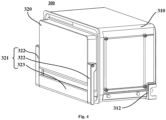
- FIG. 4 is a schematic diagram of a sealed drawer 300 in a refrigerator 10 according to an embodiment of the present invention.
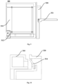
- FIG. 5 is a schematic diagram from another perspective of a sealed drawer 300 in a refrigerator 10 according to an embodiment of the present invention.
- FIG. 6 is a schematic block diagram of exhausting and ventilating members in a refrigerator 10 according to an embodiment of the present invention.
- the refrigerator 10 is provided with a ventilating device 340, where the ventilating device 340 is disposed inside the sealed barrel 310 and configured to allow communication between an internal space of the sealed barrel 310 and the first storage space when turned on, thus realizing air exchange between the internal space of the sealed barrel 310 and the first storage space.
- the refrigerator 10 according to the present invention preferably adopts air cooling for refrigeration, and the humidity in the first storage space may be reduced during refrigeration of the first storage space. Therefore, the ventilating device 340 may be turned on when the air humidity in the sealed barrel 310 is higher than the air humidity in the first storage space, so as to reduce the air humidity in the sealed barrel 310.
- Humidity detection devices are used to detect the humidity in the refrigerator body 12 and the first door 200.
- a first humidity detection device 331 is disposed inside the first storage space and configured to detect the air humidity in the first storage space.
- a second humidity detection device 332 is disposed inside the sealed barrel 310 and configured to detect the air humidity in the sealed barrel 310.
- the ventilating device 340 is further configured to be turned on when the air humidity in the sealed barrel 310 is higher than the air humidity in the first storage space.
- the refrigerator 10 may further be provided with an air exhausting device 350.
- the air exhausting device 350 is disposed inside the sealed barrel 310 and configured to be turned on when the air humidity in the sealed barrel 310 is lower than the air humidity in the first storage space, so as to vacuumize the sealed barrel 310.
- the sealed barrel 310 is provided with an accommodating cavity in one side close to the first storage space; the accommodating cavity is separated from an area where the drawable box 320 is located by a partition wall; and the air exhausting device 350 and the ventilating device 340 are disposed inside the accommodating cavity.
- a rear wall of the accommodating cavity is specially hidden in FIG. 5 .
- the accommodating cavity may be in a long strip shape, is disposed at the top or bottom of the sealed barrel 310, and provides an internal space for mounting the air exhausting device 350 and the ventilating device 340.
- the partition wall 312 may be provided with a through hole for connecting the air exhausting device 350 and the ventilating device 340 to the interior of the sealed barrel 310.
- the air exhausting device 350 may include a one-way valve 351 and a vacuum pump 352.
- the one-way valve 351 is disposed on the partition wall 312 and configured to allow only the air in the area where the drawable box 320 is located to flow toward the accommodating cavity, such that external air is prevented from entering the sealed barrel 310 via the partition wall 312.
- the vacuum pump 352 is transversely disposed inside the accommodating cavity and connected to one side, located in the accommodating cavity, of the one-way valve 351 by an air exhausting pipe (unshown in the figure).
- the ventilating device 340 may include: a ventilation valve 341, disposed on a wall, toward the first storage space, of the accommodating cavity; and a ventilation pipe (unshown in the figure), extending from the ventilation valve 341 to the partition wall 312 and in communication with the area where the drawable box 320 is located.
- the ventilating device 340 and the air exhausting device 350 are both configured to be turned on only when the first door 200 and the second door 110 are both closed, so as to prevent external air introduced after the door is opened from affecting humidity detection results of the first humidity detection device 331 and the second humidity detection device 332.
- the refrigerator according to this embodiment may further be provided with a door opening and closing detector 333.
- the door opening and closing detector 333 is configured to sense an open/close state of the first door 200 and the second door 110, so as to provide the open/close state of the first door 200 and the second door 110 for the ventilating device 340 and the air exhausting device 350.
- the door opening and closing detector 333 may detect opening and closing actions of the first door 200 and the second door 110 by means such as a contact switch, a Hall element, and a magnetosensitive element.
- An operating principle of the refrigerator according to this embodiment for maintaining the humidity of the sealed barrel 310 includes: determining that the first door 200 and the second door 110 are both closed; acquiring an air humidity in the first storage space detected by the first humidity detection device 331 and an air humidity in the sealed barrel 310 detected by the second humidity detection device 332; comparing the air humidity in the first storage space with the air humidity in the sealed barrel 310; and if the air humidity in the first storage space is higher than the air humidity in the sealed barrel 310, closing the ventilation valve 341 and starting the vacuum pump 352 to exhaust air from the sealed drawer 300.
- the ventilation valve 341 is opened, and the vacuum pump 352 is started to exchange air for the drawer 300.
- Air exhausting and/or ventilation can both be performed according to a preset time duration or started and stopped according to a temperature.
- the comparison between the air humidity in the first storage space and the air humidity in the sealed barrel 310, and the control on the ventilating device 340 and the air exhausting device 350 can both be implemented by one controller.
- the humidity detection devices are used to detect the humidity in the first storage space of the refrigerator body 12 and the humidity in the sealed barrel 310 respectively, and the ventilating device 340 and the air exhausting device 350 are used to reduce the humidity of the sealed drawer 300. That is, the humidity in the drawer 300 is reduced by using a vacuum dehumidification technology when the drawable box 320 is closed, so that the interior of the drawer 300 is kept dry, which is conducive to preservation of precious goods.
- FIG. 7 is a schematic diagram of a closed drawable box 320 in a refrigerator 10 according to an embodiment of the present invention; and FIG. 8 shows a form of a sealing element 324 in a state shown in FIG. 7 .
- FIG. 9 is a schematic diagram of a pulled-out drawable box 320 in a refrigerator 10 according to an embodiment of the present invention; and FIG. 10 shows a form of a sealing element 324 in a state shown in FIG. 9 .
- the sealing element 324 is disposed at a position where a panel of the drawable box 320 faces the sealed barrel 310, and the sealing element 324 is extruded by the panel of the drawable box 320 and the sealed barrel 310 when the drawable box 320 is closed, so as to seal a gap between the panel of the drawable box 320 and the sealed barrel 310.
- the sealing element 324 may use a silicone rubber sealing gasket embedded into a slot formed in a front panel of the drawable box 320. After the drawable box 320 is closed, the gap between the drawable box 320 and the sealed barrel 310 is sealed under the extrusion of the front panel of the drawable box 320 and the sealed barrel 310.
- the drawable box 320 may further include a pivoting handle 321.
- the pivoting handle 321 includes two pivoting arms 322 and pull rods 323. One ends of the two pivoting arms 322 are pivotally connected to two sides of the front panel of the drawable box 320 within a set rotating angle; and the pull rods 323 are connected to the other ends of the two pivoting arms 322 and configured to be held by a user to apply a force for pulling the drawable box 320 after the pivoting arms 322 rotate to a set angle.
- the pivoting handle 321 may be attached to the front side of the panel of the drawable box 320 in a normal state, and may be basically perpendicular to the panel of the drawable box 320 after pulled and reversed by a user, so as to facilitate force application of the user.
- the set rotating angle of the pivoting handle 321 may be limited by an angle limiting member, for example, an included angle between the pivoting handle 321 and the panel of the drawable box 320 is limited to be 0-90 degrees.
- FIG. 11 is a state diagram of a locking element 325 when a drawable box 320 is pulled out in a refrigerator 10 according to an embodiment of the present invention
- FIG. 12 is a state diagram of the locking element 325 when the drawable box 320 is closed in a refrigerator 10 according to an embodiment of the present invention.
- the refrigerator further includes a locking element 325 configured to limit the positions of the panel of the drawable box 320 and the sealed barrel 310 when the drawer 300 is closed.
- the locking element 325 may be linked with the pivoting handle 321, and performs unlocking when the pivoting handle 321 is pulled out; and the positions of the sealed barrel 310 and the drawable box 320 are locked when the pivoting handle 321 is put back.
- the locking element 325 may be a structure provided with limiting posts 326 and limiting grooves 327 cooperating with each other.
- the limiting posts 326 extend from front ends disposed at two sides of the sealed barrel 310 toward the panel of the drawable box 320; and the limiting grooves 327 are formed on two sides of the panel of the drawable box 320 and configured to cooperate with the limiting posts 326 to lock the position of the drawable box 320.
- Each of the limiting grooves 327 includes a horizontal section toward the sealed barrel 310, where the horizontal sections are for the limiting posts 326 to enter in a pulling direction of the drawable box 320; each of the limiting grooves 327 is provided with an accommodating groove in the tail end along a height direction; and each of the limiting posts 326 enters the corresponding accommodating groove along the height direction after reaching the tail end of the corresponding horizontal section, thus realizing locking.
- the drawable box 320 is pulled out, a user lifts the pivoting handle 321, the limiting posts 326 are released from the accommodating grooves and can be released from the accommodating grooves along the pulling direction of the drawable box 320.
- the sealed drawer 300 is sealed by extrusion of a sealing element (such as a silicone rubber sealing gasket), and can be conveniently sealed and unlocked by using the pivoting handle 321 based on structural improvement. This facilitates operation of users.
- a sealing element such as a silicone rubber sealing gasket
Landscapes
- Engineering & Computer Science (AREA)
- Chemical & Material Sciences (AREA)
- Combustion & Propulsion (AREA)
- Physics & Mathematics (AREA)
- Mechanical Engineering (AREA)
- Thermal Sciences (AREA)
- General Engineering & Computer Science (AREA)
- Refrigerator Housings (AREA)
- Cold Air Circulating Systems And Constructional Details In Refrigerators (AREA)
Claims (9)
- Kühlschrank (10) mit einer versiegelten Schublade (300) an einem Türkörper (11), der folgende umfasst:einen Kühlschrankkörper (12), der einen ersten Lagerraum definiert;eine erste Tür (200), die drehbar an einem vorderen Abschnitt des Kühlschrankkörpers angebracht ist und zum Öffnen und Schließen des ersten Lagerraums konfiguriert ist;ein versiegelter Fass (310), das innerhalb der ersten Tür angeordnet ist und mit einer Öffnung auf einer Seite versehen ist, die vom ersten Lagerraum entfernt ist;einen ziehbaren Kasten (320), der in dem verschlossenen Fass auf ziehbare Weise über die Öffnung angeordnet ist; dadurch gekennzeichnet, dass der Kühlschrank (10) ferner umfasst:eine Belüftungsvorrichtung (340), die innerhalb des versiegelten Fasses angeordnet ist und so konfiguriert ist, dass sie beim Einschalten eine Kommunikation zwischen einem Innenraum des versiegelten Fasses und dem ersten Lagerraum ermöglicht, wodurch ein Luftaustausch zwischen dem Innenraum des versiegelten Fasses und dem ersten Lagerraum realisiert wird;eine erste Feuchtigkeitserfassungsvorrichtung (331), die innerhalb des ersten Lagerraums angeordnet ist und so konfiguriert ist, um eine Luftfeuchtigkeit im ersten Lagerraum zu erfassen; undeine zweite Feuchtigkeitserfassungsvorrichtung (332), die innerhalb des versiegelten Fasses angeordnet ist und so konfiguriert ist, um eine Luftfeuchtigkeit im versiegelten Fass zu erfassen; undwobei die Belüftungsvorrichtung ferner so konfiguriert ist, dass sie eingeschaltet wird, wenn die Luftfeuchtigkeit im versiegelten Fass höher als die Luftfeuchtigkeit im ersten Lagerraum ist.
- Kühlschrank (10) mit einer versiegelten Schublade an einem Türkörper gemäß Anspruch 1, der folgende umfasst:
eine Luftablassvorrichtung (350), die im Inneren des versiegelten Fasses angeordnet ist und so konfiguriert ist, dass sie zum Saugen des versiegelten Fasses eingeschaltet werden kann, wenn die Luftfeuchtigkeit im versiegelten Fass niedriger als die Luftfeuchtigkeit im ersten Lagerraum ist. - Kühlschrank (10) mit einer versiegelten Schublade an einem Türkörper gemäß Anspruch 2, wobeidas versiegelte Fass auf einer Seite in der Nähe des ersten Lagerraums mit einem Aufnahmehohlraum versehen ist, wobei der Aufnahmehohlraum von einem Bereich, in dem sich der ziehbare Kasten befindet, durch eine Trennwand (312) getrennt ist; undwobei die Luftablassvorrichtung und die Belüftungsvorrichtung innerhalb des Aufnahmehohlraums angeordnet sind.
- Kühlschrank (10) mit einer versiegelten Schublade an einem Türkörper gemäß Anspruch 3, wobei die Luftablassvorrichtung folgende umfasst:ein Einwegventil (351), das an der Trennwand angeordnet ist und so konfiguriert ist, dass nur die Luft in dem Bereich, in dem sich die ziehbare Kaste befindet, in Richtung des Aufnahmehohlraums fließen kann; undeine Vakuumpumpe (352), die quer in dem Aufnahmehohlraum angeordnet ist und durch ein Luftauslassrohr mit einer Seite des Einwegventils verbunden ist, das sich in dem Aufnahmehohlraum befindet.
- Kühlschrank (10) mit einer versiegelten Schublade an einem Türkörper gemäß Anspruch 3 oder 4, wobei die Belüftungsvorrichtung folgende umfasst:ein Lüftungsventil (341), das an einer Wand des Aufnahmehohlraum in Richtung des ersten Lagerraums angeordnet ist; undein Lüftungsrohr, das sich vom Lüftungsventil bis zur Trennwand erstreckt und mit dem Bereich verbindet ist, in dem sich der abziehbare Kasten befindet.
- Kühlschrank (10) mit einer versiegelten Schublade an einem Türkörper gemäß einem der Ansprüche 2 bis 5, der ferner umfasst:eine zweite Tür (110), die drehbar an einer Seite der ersten Tür (200) angeordnet ist, die von dem Kühlschrankkörper (12) entfernt ist; undein Türöffnungs- und Schließdetektor (333), der konfiguriert ist, um einen Öffnungs-/Schließzustand der ersten Tür und der zweiten Tür zu erfassen; undwobei die Luftablassvorrichtung ferner so konfiguriert ist, dass sie nur eingeschaltet werden kann, wenn die erste und die zweite Tür beide geschlossen sind.
- Kühlschrank (10) mit einer versiegelten Schublade an einem Türkörper gemäß einem der Ansprüche 1 bis 6, der ferner umfasst:
ein Dichtungselement (324), das an einer Position angeordnet ist, in der eine Platte des ziehbaren Kastens dem versiegelten Fass zugewandt ist, wobei das Dichtungselement durch die Platte des ziehbaren Kastens und das versiegelte Fass extrudiert wird, wenn der ziehbare Kasten geschlossen wird, um einen Spalt zwischen der Platte des ziehbaren Kastens und dem versiegelten Fass abzudichten. - Kühlschrank (10) mit einer versiegelten Schublade an einem Türkörper gemäß Anspruch 7, der folgende umfasst:
ein Verriegelungselement (325), das so konfiguriert ist, dass es die Positionen der Platte des ziehbaren Kastens und des versiegelten Fasses begrenzt, wenn der ziehbare Kasten geschlossen ist, und umfassend:Begrenzungsstangen (326), die sich von den vorderen Enden, die an zwei Seiten des versiegelten Fasses angeordnet sind, in Richtung der Platte des ziehbaren Kastens erstrecken; undBegrenzungsnuten (327), die auf beiden Seiten der Platte des ziehbaren Kastens ausgebildet sind und so konfiguriert sind, dass sie mit den Begrenzungsstangen zusammenarbeiten, um die Position des ziehbaren Kastens zu sperren. - Kühlschrank (10) mit einer versiegelten Schublade an einem Türkörper gemäß Anspruch 7 oder 8, wobei der ziehbare Kasten ferner umfasst:
einen Schwenkgriff (321), der umfasst:zwei Schwenkarme (322), deren eines Ende jeweils innerhalb eines eingestellten Drehwinkels schwenkbar mit beiden Seiten der Frontplatte des ziehbaren Kastens verbunden ist; undZugstäbe (323), die an die anderen Enden der beiden Schwenkarme verbunden sind und so konfiguriert sind, dass der Benutzer gehalten werden kann, um eine Kraft zum Ziehen des ziehbaren Kastens auszuüben, nachdem die Schwenkarme auf einen eingestellten Winkel gedreht werden.
Applications Claiming Priority (2)
| Application Number | Priority Date | Filing Date | Title |
|---|---|---|---|
| CN202010969235.7A CN114183969A (zh) | 2020-09-15 | 2020-09-15 | 在门体上设置密封抽屉的冰箱 |
| PCT/CN2021/115629 WO2022057611A1 (zh) | 2020-09-15 | 2021-08-31 | 在门体上设置密封抽屉的冰箱 |
Publications (3)
| Publication Number | Publication Date |
|---|---|
| EP4206571A1 EP4206571A1 (de) | 2023-07-05 |
| EP4206571A4 EP4206571A4 (de) | 2024-01-10 |
| EP4206571B1 true EP4206571B1 (de) | 2025-02-12 |
Family
ID=80539202
Family Applications (1)
| Application Number | Title | Priority Date | Filing Date |
|---|---|---|---|
| EP21868438.9A Active EP4206571B1 (de) | 2020-09-15 | 2021-08-31 | Kühlschrank mit abgedichteter schublade an der türkarosserie |
Country Status (5)
| Country | Link |
|---|---|
| US (1) | US20230366614A1 (de) |
| EP (1) | EP4206571B1 (de) |
| CN (1) | CN114183969A (de) |
| AU (1) | AU2021345713B2 (de) |
| WO (1) | WO2022057611A1 (de) |
Families Citing this family (1)
| Publication number | Priority date | Publication date | Assignee | Title |
|---|---|---|---|---|
| WO2025039460A1 (zh) * | 2023-08-21 | 2025-02-27 | 海信容声(广东)冰箱有限公司 | 冰箱 |
Family Cites Families (12)
| Publication number | Priority date | Publication date | Assignee | Title |
|---|---|---|---|---|
| US2136558A (en) * | 1935-09-20 | 1938-11-15 | Manshel Charles | Refrigerator |
| US2656688A (en) * | 1951-10-15 | 1953-10-27 | Int Harvester Co | Refrigerator door with a compartment |
| CN102494480A (zh) * | 2011-12-05 | 2012-06-13 | 合肥美的荣事达电冰箱有限公司 | 一种冰箱门体和具有该冰箱门体的冰箱 |
| CN102494483B (zh) * | 2011-12-05 | 2014-04-16 | 合肥美的电冰箱有限公司 | 一种冰箱门体和具有该冰箱门体的冰箱 |
| CN104949466B (zh) * | 2015-06-30 | 2018-02-13 | 合肥华凌股份有限公司 | 一种湿度控制装置、保藏箱和冰箱 |
| CN205300090U (zh) * | 2015-10-21 | 2016-06-08 | 海信容声(广东)冰箱有限公司 | 冰箱用门及冰箱 |
| CN105444489A (zh) * | 2015-12-02 | 2016-03-30 | 海信容声(广东)冰箱有限公司 | 一种冰箱 |
| CN205641780U (zh) * | 2015-12-29 | 2016-10-12 | 青岛海尔股份有限公司 | 冰箱 |
| KR20170114580A (ko) * | 2016-04-05 | 2017-10-16 | 엘지전자 주식회사 | 냉장고 |
| KR102550655B1 (ko) * | 2016-07-29 | 2023-07-03 | 엘지전자 주식회사 | 냉장고 및 바스켓 어셈블리 |
| CH714572A1 (de) * | 2018-01-18 | 2019-07-31 | Novaris Gmbh | Deckel für einen Schubladenkorpus und Vakuumschubladeneinrichtung mit einem Deckel. |
| CN212378332U (zh) * | 2020-09-15 | 2021-01-19 | 青岛海尔电冰箱有限公司 | 在门体上设置密封抽屉的冰箱 |
-
2020
- 2020-09-15 CN CN202010969235.7A patent/CN114183969A/zh active Pending
-
2021
- 2021-08-31 AU AU2021345713A patent/AU2021345713B2/en active Active
- 2021-08-31 EP EP21868438.9A patent/EP4206571B1/de active Active
- 2021-08-31 US US18/245,198 patent/US20230366614A1/en not_active Abandoned
- 2021-08-31 WO PCT/CN2021/115629 patent/WO2022057611A1/zh not_active Ceased
Also Published As
| Publication number | Publication date |
|---|---|
| EP4206571A4 (de) | 2024-01-10 |
| CN114183969A (zh) | 2022-03-15 |
| US20230366614A1 (en) | 2023-11-16 |
| WO2022057611A1 (zh) | 2022-03-24 |
| AU2021345713A1 (en) | 2023-05-11 |
| EP4206571A1 (de) | 2023-07-05 |
| AU2021345713B2 (en) | 2024-09-19 |
Similar Documents
| Publication | Publication Date | Title |
|---|---|---|
| CN211204583U (zh) | 冰箱 | |
| CN102338538B (zh) | 储藏单元以及具有储藏单元的制冷器具 | |
| WO2021227421A1 (zh) | 冰箱 | |
| CN102338539B (zh) | 储藏单元以及具有储藏单元的制冷器具 | |
| JP2024026409A (ja) | 冷蔵庫 | |
| EP4206571B1 (de) | Kühlschrank mit abgedichteter schublade an der türkarosserie | |
| WO2021114956A1 (zh) | 冰箱 | |
| CN102338541B (zh) | 储藏单元以及具有储藏单元的制冷器具 | |
| CN212378332U (zh) | 在门体上设置密封抽屉的冰箱 | |
| CN102338540B (zh) | 储藏单元以及具有储藏单元的制冷器具 | |
| CN111207553A (zh) | 冰箱 | |
| WO2021114961A1 (zh) | 冰箱 | |
| KR101988306B1 (ko) | 냉장고 | |
| WO2021114959A1 (zh) | 冰箱 | |
| WO2021114958A1 (zh) | 冰箱 | |
| WO2021114957A1 (zh) | 冰箱 |
Legal Events
| Date | Code | Title | Description |
|---|---|---|---|
| STAA | Information on the status of an ep patent application or granted ep patent |
Free format text: STATUS: THE INTERNATIONAL PUBLICATION HAS BEEN MADE |
|
| PUAI | Public reference made under article 153(3) epc to a published international application that has entered the european phase |
Free format text: ORIGINAL CODE: 0009012 |
|
| STAA | Information on the status of an ep patent application or granted ep patent |
Free format text: STATUS: REQUEST FOR EXAMINATION WAS MADE |
|
| 17P | Request for examination filed |
Effective date: 20230330 |
|
| AK | Designated contracting states |
Kind code of ref document: A1 Designated state(s): AL AT BE BG CH CY CZ DE DK EE ES FI FR GB GR HR HU IE IS IT LI LT LU LV MC MK MT NL NO PL PT RO RS SE SI SK SM TR |
|
| DAV | Request for validation of the european patent (deleted) | ||
| DAX | Request for extension of the european patent (deleted) | ||
| STAA | Information on the status of an ep patent application or granted ep patent |
Free format text: STATUS: EXAMINATION IS IN PROGRESS |
|
| A4 | Supplementary search report drawn up and despatched |
Effective date: 20231211 |
|
| RIC1 | Information provided on ipc code assigned before grant |
Ipc: F25D 11/02 20060101AFI20231206BHEP |
|
| 17Q | First examination report despatched |
Effective date: 20231222 |
|
| GRAP | Despatch of communication of intention to grant a patent |
Free format text: ORIGINAL CODE: EPIDOSNIGR1 |
|
| STAA | Information on the status of an ep patent application or granted ep patent |
Free format text: STATUS: GRANT OF PATENT IS INTENDED |
|
| INTG | Intention to grant announced |
Effective date: 20241014 |
|
| GRAS | Grant fee paid |
Free format text: ORIGINAL CODE: EPIDOSNIGR3 |
|
| GRAA | (expected) grant |
Free format text: ORIGINAL CODE: 0009210 |
|
| STAA | Information on the status of an ep patent application or granted ep patent |
Free format text: STATUS: THE PATENT HAS BEEN GRANTED |
|
| AK | Designated contracting states |
Kind code of ref document: B1 Designated state(s): AL AT BE BG CH CY CZ DE DK EE ES FI FR GB GR HR HU IE IS IT LI LT LU LV MC MK MT NL NO PL PT RO RS SE SI SK SM TR |
|
| REG | Reference to a national code |
Ref country code: GB Ref legal event code: FG4D |
|
| REG | Reference to a national code |
Ref country code: CH Ref legal event code: EP |
|
| REG | Reference to a national code |
Ref country code: DE Ref legal event code: R096 Ref document number: 602021026172 Country of ref document: DE |
|
| REG | Reference to a national code |
Ref country code: IE Ref legal event code: FG4D |
|
| REG | Reference to a national code |
Ref country code: NL Ref legal event code: MP Effective date: 20250212 |
|
| PG25 | Lapsed in a contracting state [announced via postgrant information from national office to epo] |
Ref country code: RS Free format text: LAPSE BECAUSE OF FAILURE TO SUBMIT A TRANSLATION OF THE DESCRIPTION OR TO PAY THE FEE WITHIN THE PRESCRIBED TIME-LIMIT Effective date: 20250512 |
|
| PG25 | Lapsed in a contracting state [announced via postgrant information from national office to epo] |
Ref country code: FI Free format text: LAPSE BECAUSE OF FAILURE TO SUBMIT A TRANSLATION OF THE DESCRIPTION OR TO PAY THE FEE WITHIN THE PRESCRIBED TIME-LIMIT Effective date: 20250212 |
|
| PG25 | Lapsed in a contracting state [announced via postgrant information from national office to epo] |
Ref country code: PL Free format text: LAPSE BECAUSE OF FAILURE TO SUBMIT A TRANSLATION OF THE DESCRIPTION OR TO PAY THE FEE WITHIN THE PRESCRIBED TIME-LIMIT Effective date: 20250212 |
|
| PG25 | Lapsed in a contracting state [announced via postgrant information from national office to epo] |
Ref country code: ES Free format text: LAPSE BECAUSE OF FAILURE TO SUBMIT A TRANSLATION OF THE DESCRIPTION OR TO PAY THE FEE WITHIN THE PRESCRIBED TIME-LIMIT Effective date: 20250212 |
|
| REG | Reference to a national code |
Ref country code: LT Ref legal event code: MG9D |
|
| PG25 | Lapsed in a contracting state [announced via postgrant information from national office to epo] |
Ref country code: NO Free format text: LAPSE BECAUSE OF FAILURE TO SUBMIT A TRANSLATION OF THE DESCRIPTION OR TO PAY THE FEE WITHIN THE PRESCRIBED TIME-LIMIT Effective date: 20250512 Ref country code: IS Free format text: LAPSE BECAUSE OF FAILURE TO SUBMIT A TRANSLATION OF THE DESCRIPTION OR TO PAY THE FEE WITHIN THE PRESCRIBED TIME-LIMIT Effective date: 20250612 |
|
| PG25 | Lapsed in a contracting state [announced via postgrant information from national office to epo] |
Ref country code: NL Free format text: LAPSE BECAUSE OF FAILURE TO SUBMIT A TRANSLATION OF THE DESCRIPTION OR TO PAY THE FEE WITHIN THE PRESCRIBED TIME-LIMIT Effective date: 20250212 |
|
| PG25 | Lapsed in a contracting state [announced via postgrant information from national office to epo] |
Ref country code: HR Free format text: LAPSE BECAUSE OF FAILURE TO SUBMIT A TRANSLATION OF THE DESCRIPTION OR TO PAY THE FEE WITHIN THE PRESCRIBED TIME-LIMIT Effective date: 20250212 |
|
| PG25 | Lapsed in a contracting state [announced via postgrant information from national office to epo] |
Ref country code: LV Free format text: LAPSE BECAUSE OF FAILURE TO SUBMIT A TRANSLATION OF THE DESCRIPTION OR TO PAY THE FEE WITHIN THE PRESCRIBED TIME-LIMIT Effective date: 20250212 Ref country code: PT Free format text: LAPSE BECAUSE OF FAILURE TO SUBMIT A TRANSLATION OF THE DESCRIPTION OR TO PAY THE FEE WITHIN THE PRESCRIBED TIME-LIMIT Effective date: 20250612 |
|
| PG25 | Lapsed in a contracting state [announced via postgrant information from national office to epo] |
Ref country code: BG Free format text: LAPSE BECAUSE OF FAILURE TO SUBMIT A TRANSLATION OF THE DESCRIPTION OR TO PAY THE FEE WITHIN THE PRESCRIBED TIME-LIMIT Effective date: 20250212 Ref country code: GR Free format text: LAPSE BECAUSE OF FAILURE TO SUBMIT A TRANSLATION OF THE DESCRIPTION OR TO PAY THE FEE WITHIN THE PRESCRIBED TIME-LIMIT Effective date: 20250513 |
|
| REG | Reference to a national code |
Ref country code: AT Ref legal event code: MK05 Ref document number: 1766379 Country of ref document: AT Kind code of ref document: T Effective date: 20250212 |
|
| PG25 | Lapsed in a contracting state [announced via postgrant information from national office to epo] |
Ref country code: SE Free format text: LAPSE BECAUSE OF FAILURE TO SUBMIT A TRANSLATION OF THE DESCRIPTION OR TO PAY THE FEE WITHIN THE PRESCRIBED TIME-LIMIT Effective date: 20250212 |
|
| PG25 | Lapsed in a contracting state [announced via postgrant information from national office to epo] |
Ref country code: SM Free format text: LAPSE BECAUSE OF FAILURE TO SUBMIT A TRANSLATION OF THE DESCRIPTION OR TO PAY THE FEE WITHIN THE PRESCRIBED TIME-LIMIT Effective date: 20250212 |
|
| PG25 | Lapsed in a contracting state [announced via postgrant information from national office to epo] |
Ref country code: DK Free format text: LAPSE BECAUSE OF FAILURE TO SUBMIT A TRANSLATION OF THE DESCRIPTION OR TO PAY THE FEE WITHIN THE PRESCRIBED TIME-LIMIT Effective date: 20250212 |
|
| PGFP | Annual fee paid to national office [announced via postgrant information from national office to epo] |
Ref country code: DE Payment date: 20250812 Year of fee payment: 5 |
|
| PG25 | Lapsed in a contracting state [announced via postgrant information from national office to epo] |
Ref country code: IT Free format text: LAPSE BECAUSE OF FAILURE TO SUBMIT A TRANSLATION OF THE DESCRIPTION OR TO PAY THE FEE WITHIN THE PRESCRIBED TIME-LIMIT Effective date: 20250212 |
|
| PGFP | Annual fee paid to national office [announced via postgrant information from national office to epo] |
Ref country code: GB Payment date: 20250826 Year of fee payment: 5 |
|
| PG25 | Lapsed in a contracting state [announced via postgrant information from national office to epo] |
Ref country code: AT Free format text: LAPSE BECAUSE OF FAILURE TO SUBMIT A TRANSLATION OF THE DESCRIPTION OR TO PAY THE FEE WITHIN THE PRESCRIBED TIME-LIMIT Effective date: 20250212 |
|
| PGFP | Annual fee paid to national office [announced via postgrant information from national office to epo] |
Ref country code: FR Payment date: 20250828 Year of fee payment: 5 |
|
| PG25 | Lapsed in a contracting state [announced via postgrant information from national office to epo] |
Ref country code: EE Free format text: LAPSE BECAUSE OF FAILURE TO SUBMIT A TRANSLATION OF THE DESCRIPTION OR TO PAY THE FEE WITHIN THE PRESCRIBED TIME-LIMIT Effective date: 20250212 Ref country code: CZ Free format text: LAPSE BECAUSE OF FAILURE TO SUBMIT A TRANSLATION OF THE DESCRIPTION OR TO PAY THE FEE WITHIN THE PRESCRIBED TIME-LIMIT Effective date: 20250212 |
|
| PG25 | Lapsed in a contracting state [announced via postgrant information from national office to epo] |
Ref country code: RO Free format text: LAPSE BECAUSE OF FAILURE TO SUBMIT A TRANSLATION OF THE DESCRIPTION OR TO PAY THE FEE WITHIN THE PRESCRIBED TIME-LIMIT Effective date: 20250212 |
|
| PG25 | Lapsed in a contracting state [announced via postgrant information from national office to epo] |
Ref country code: SK Free format text: LAPSE BECAUSE OF FAILURE TO SUBMIT A TRANSLATION OF THE DESCRIPTION OR TO PAY THE FEE WITHIN THE PRESCRIBED TIME-LIMIT Effective date: 20250212 |
|
| REG | Reference to a national code |
Ref country code: DE Ref legal event code: R097 Ref document number: 602021026172 Country of ref document: DE |
|
| PLBE | No opposition filed within time limit |
Free format text: ORIGINAL CODE: 0009261 |
|
| STAA | Information on the status of an ep patent application or granted ep patent |
Free format text: STATUS: NO OPPOSITION FILED WITHIN TIME LIMIT |
|
| REG | Reference to a national code |
Ref country code: CH Ref legal event code: L10 Free format text: ST27 STATUS EVENT CODE: U-0-0-L10-L00 (AS PROVIDED BY THE NATIONAL OFFICE) Effective date: 20251224 |
|
| 26N | No opposition filed |
Effective date: 20251113 |
|
| REG | Reference to a national code |
Ref country code: CH Ref legal event code: H13 Free format text: ST27 STATUS EVENT CODE: U-0-0-H10-H13 (AS PROVIDED BY THE NATIONAL OFFICE) Effective date: 20260324 |
|
| PG25 | Lapsed in a contracting state [announced via postgrant information from national office to epo] |
Ref country code: MC Free format text: LAPSE BECAUSE OF FAILURE TO SUBMIT A TRANSLATION OF THE DESCRIPTION OR TO PAY THE FEE WITHIN THE PRESCRIBED TIME-LIMIT Effective date: 20250212 |
|
| PG25 | Lapsed in a contracting state [announced via postgrant information from national office to epo] |
Ref country code: LU Free format text: LAPSE BECAUSE OF NON-PAYMENT OF DUE FEES Effective date: 20250831 |