EP4206565A1 - Refrigeration cycle device - Google Patents
Refrigeration cycle device Download PDFInfo
- Publication number
- EP4206565A1 EP4206565A1 EP21861156.4A EP21861156A EP4206565A1 EP 4206565 A1 EP4206565 A1 EP 4206565A1 EP 21861156 A EP21861156 A EP 21861156A EP 4206565 A1 EP4206565 A1 EP 4206565A1
- Authority
- EP
- European Patent Office
- Prior art keywords
- refrigerant
- acid capturing
- liquid
- flow channel
- refrigeration cycle
- Prior art date
- Legal status (The legal status is an assumption and is not a legal conclusion. Google has not performed a legal analysis and makes no representation as to the accuracy of the status listed.)
- Withdrawn
Links
Images

Classifications
-
- F—MECHANICAL ENGINEERING; LIGHTING; HEATING; WEAPONS; BLASTING
- F25—REFRIGERATION OR COOLING; COMBINED HEATING AND REFRIGERATION SYSTEMS; HEAT PUMP SYSTEMS; MANUFACTURE OR STORAGE OF ICE; LIQUEFACTION SOLIDIFICATION OF GASES
- F25B—REFRIGERATION MACHINES, PLANTS OR SYSTEMS; COMBINED HEATING AND REFRIGERATION SYSTEMS; HEAT PUMP SYSTEMS
- F25B43/00—Arrangements for separating or purifying gases or liquids; Arrangements for vaporising the residuum of liquid refrigerant, e.g. by heat
- F25B43/003—Filters
-
- F—MECHANICAL ENGINEERING; LIGHTING; HEATING; WEAPONS; BLASTING
- F25—REFRIGERATION OR COOLING; COMBINED HEATING AND REFRIGERATION SYSTEMS; HEAT PUMP SYSTEMS; MANUFACTURE OR STORAGE OF ICE; LIQUEFACTION SOLIDIFICATION OF GASES
- F25B—REFRIGERATION MACHINES, PLANTS OR SYSTEMS; COMBINED HEATING AND REFRIGERATION SYSTEMS; HEAT PUMP SYSTEMS
- F25B13/00—Compression machines, plants or systems, with reversible cycle
-
- F—MECHANICAL ENGINEERING; LIGHTING; HEATING; WEAPONS; BLASTING
- F25—REFRIGERATION OR COOLING; COMBINED HEATING AND REFRIGERATION SYSTEMS; HEAT PUMP SYSTEMS; MANUFACTURE OR STORAGE OF ICE; LIQUEFACTION SOLIDIFICATION OF GASES
- F25B—REFRIGERATION MACHINES, PLANTS OR SYSTEMS; COMBINED HEATING AND REFRIGERATION SYSTEMS; HEAT PUMP SYSTEMS
- F25B31/00—Compressor arrangements
- F25B31/002—Lubrication
- F25B31/004—Lubrication oil recirculating arrangements
-
- F—MECHANICAL ENGINEERING; LIGHTING; HEATING; WEAPONS; BLASTING
- F25—REFRIGERATION OR COOLING; COMBINED HEATING AND REFRIGERATION SYSTEMS; HEAT PUMP SYSTEMS; MANUFACTURE OR STORAGE OF ICE; LIQUEFACTION SOLIDIFICATION OF GASES
- F25B—REFRIGERATION MACHINES, PLANTS OR SYSTEMS; COMBINED HEATING AND REFRIGERATION SYSTEMS; HEAT PUMP SYSTEMS
- F25B40/00—Subcoolers, desuperheaters or superheaters
- F25B40/02—Subcoolers
-
- F—MECHANICAL ENGINEERING; LIGHTING; HEATING; WEAPONS; BLASTING
- F25—REFRIGERATION OR COOLING; COMBINED HEATING AND REFRIGERATION SYSTEMS; HEAT PUMP SYSTEMS; MANUFACTURE OR STORAGE OF ICE; LIQUEFACTION SOLIDIFICATION OF GASES
- F25B—REFRIGERATION MACHINES, PLANTS OR SYSTEMS; COMBINED HEATING AND REFRIGERATION SYSTEMS; HEAT PUMP SYSTEMS
- F25B41/00—Fluid-circulation arrangements
- F25B41/20—Disposition of valves, e.g. of on-off valves or flow control valves
-
- F—MECHANICAL ENGINEERING; LIGHTING; HEATING; WEAPONS; BLASTING
- F25—REFRIGERATION OR COOLING; COMBINED HEATING AND REFRIGERATION SYSTEMS; HEAT PUMP SYSTEMS; MANUFACTURE OR STORAGE OF ICE; LIQUEFACTION SOLIDIFICATION OF GASES
- F25B—REFRIGERATION MACHINES, PLANTS OR SYSTEMS; COMBINED HEATING AND REFRIGERATION SYSTEMS; HEAT PUMP SYSTEMS
- F25B41/00—Fluid-circulation arrangements
- F25B41/20—Disposition of valves, e.g. of on-off valves or flow control valves
- F25B41/24—Arrangement of shut-off valves for disconnecting a part of the refrigerant cycle, e.g. an outdoor part
-
- F—MECHANICAL ENGINEERING; LIGHTING; HEATING; WEAPONS; BLASTING
- F25—REFRIGERATION OR COOLING; COMBINED HEATING AND REFRIGERATION SYSTEMS; HEAT PUMP SYSTEMS; MANUFACTURE OR STORAGE OF ICE; LIQUEFACTION SOLIDIFICATION OF GASES
- F25B—REFRIGERATION MACHINES, PLANTS OR SYSTEMS; COMBINED HEATING AND REFRIGERATION SYSTEMS; HEAT PUMP SYSTEMS
- F25B41/00—Fluid-circulation arrangements
- F25B41/40—Fluid line arrangements
- F25B41/42—Arrangements for diverging or converging flows, e.g. branch lines or junctions
-
- F—MECHANICAL ENGINEERING; LIGHTING; HEATING; WEAPONS; BLASTING
- F25—REFRIGERATION OR COOLING; COMBINED HEATING AND REFRIGERATION SYSTEMS; HEAT PUMP SYSTEMS; MANUFACTURE OR STORAGE OF ICE; LIQUEFACTION SOLIDIFICATION OF GASES
- F25B—REFRIGERATION MACHINES, PLANTS OR SYSTEMS; COMBINED HEATING AND REFRIGERATION SYSTEMS; HEAT PUMP SYSTEMS
- F25B43/00—Arrangements for separating or purifying gases or liquids; Arrangements for vaporising the residuum of liquid refrigerant, e.g. by heat
-
- F—MECHANICAL ENGINEERING; LIGHTING; HEATING; WEAPONS; BLASTING
- F25—REFRIGERATION OR COOLING; COMBINED HEATING AND REFRIGERATION SYSTEMS; HEAT PUMP SYSTEMS; MANUFACTURE OR STORAGE OF ICE; LIQUEFACTION SOLIDIFICATION OF GASES
- F25B—REFRIGERATION MACHINES, PLANTS OR SYSTEMS; COMBINED HEATING AND REFRIGERATION SYSTEMS; HEAT PUMP SYSTEMS
- F25B43/00—Arrangements for separating or purifying gases or liquids; Arrangements for vaporising the residuum of liquid refrigerant, e.g. by heat
- F25B43/006—Accumulators
-
- F—MECHANICAL ENGINEERING; LIGHTING; HEATING; WEAPONS; BLASTING
- F25—REFRIGERATION OR COOLING; COMBINED HEATING AND REFRIGERATION SYSTEMS; HEAT PUMP SYSTEMS; MANUFACTURE OR STORAGE OF ICE; LIQUEFACTION SOLIDIFICATION OF GASES
- F25B—REFRIGERATION MACHINES, PLANTS OR SYSTEMS; COMBINED HEATING AND REFRIGERATION SYSTEMS; HEAT PUMP SYSTEMS
- F25B43/00—Arrangements for separating or purifying gases or liquids; Arrangements for vaporising the residuum of liquid refrigerant, e.g. by heat
- F25B43/02—Arrangements for separating or purifying gases or liquids; Arrangements for vaporising the residuum of liquid refrigerant, e.g. by heat for separating lubricants from the refrigerant
-
- F—MECHANICAL ENGINEERING; LIGHTING; HEATING; WEAPONS; BLASTING
- F25—REFRIGERATION OR COOLING; COMBINED HEATING AND REFRIGERATION SYSTEMS; HEAT PUMP SYSTEMS; MANUFACTURE OR STORAGE OF ICE; LIQUEFACTION SOLIDIFICATION OF GASES
- F25B—REFRIGERATION MACHINES, PLANTS OR SYSTEMS; COMBINED HEATING AND REFRIGERATION SYSTEMS; HEAT PUMP SYSTEMS
- F25B49/00—Arrangement or mounting of control or safety devices
- F25B49/02—Arrangement or mounting of control or safety devices for compression type machines, plants or systems
-
- F—MECHANICAL ENGINEERING; LIGHTING; HEATING; WEAPONS; BLASTING
- F25—REFRIGERATION OR COOLING; COMBINED HEATING AND REFRIGERATION SYSTEMS; HEAT PUMP SYSTEMS; MANUFACTURE OR STORAGE OF ICE; LIQUEFACTION SOLIDIFICATION OF GASES
- F25B—REFRIGERATION MACHINES, PLANTS OR SYSTEMS; COMBINED HEATING AND REFRIGERATION SYSTEMS; HEAT PUMP SYSTEMS
- F25B2400/00—Component parts or details not otherwise provided for in this subclass
- F25B2400/04—Refrigeration circuit bypassing means
- F25B2400/0409—Refrigeration circuit bypassing means for evaporators
-
- F—MECHANICAL ENGINEERING; LIGHTING; HEATING; WEAPONS; BLASTING
- F25—REFRIGERATION OR COOLING; COMBINED HEATING AND REFRIGERATION SYSTEMS; HEAT PUMP SYSTEMS; MANUFACTURE OR STORAGE OF ICE; LIQUEFACTION SOLIDIFICATION OF GASES
- F25B—REFRIGERATION MACHINES, PLANTS OR SYSTEMS; COMBINED HEATING AND REFRIGERATION SYSTEMS; HEAT PUMP SYSTEMS
- F25B2400/00—Component parts or details not otherwise provided for in this subclass
- F25B2400/12—Inflammable refrigerants
-
- F—MECHANICAL ENGINEERING; LIGHTING; HEATING; WEAPONS; BLASTING
- F25—REFRIGERATION OR COOLING; COMBINED HEATING AND REFRIGERATION SYSTEMS; HEAT PUMP SYSTEMS; MANUFACTURE OR STORAGE OF ICE; LIQUEFACTION SOLIDIFICATION OF GASES
- F25B—REFRIGERATION MACHINES, PLANTS OR SYSTEMS; COMBINED HEATING AND REFRIGERATION SYSTEMS; HEAT PUMP SYSTEMS
- F25B2400/00—Component parts or details not otherwise provided for in this subclass
- F25B2400/23—Separators
-
- F—MECHANICAL ENGINEERING; LIGHTING; HEATING; WEAPONS; BLASTING
- F25—REFRIGERATION OR COOLING; COMBINED HEATING AND REFRIGERATION SYSTEMS; HEAT PUMP SYSTEMS; MANUFACTURE OR STORAGE OF ICE; LIQUEFACTION SOLIDIFICATION OF GASES
- F25B—REFRIGERATION MACHINES, PLANTS OR SYSTEMS; COMBINED HEATING AND REFRIGERATION SYSTEMS; HEAT PUMP SYSTEMS
- F25B2600/00—Control issues
- F25B2600/02—Compressor control
- F25B2600/021—Inverters therefor
-
- F—MECHANICAL ENGINEERING; LIGHTING; HEATING; WEAPONS; BLASTING
- F25—REFRIGERATION OR COOLING; COMBINED HEATING AND REFRIGERATION SYSTEMS; HEAT PUMP SYSTEMS; MANUFACTURE OR STORAGE OF ICE; LIQUEFACTION SOLIDIFICATION OF GASES
- F25B—REFRIGERATION MACHINES, PLANTS OR SYSTEMS; COMBINED HEATING AND REFRIGERATION SYSTEMS; HEAT PUMP SYSTEMS
- F25B2600/00—Control issues
- F25B2600/02—Compressor control
- F25B2600/027—Compressor control by controlling pressure
- F25B2600/0271—Compressor control by controlling pressure the discharge pressure
-
- F—MECHANICAL ENGINEERING; LIGHTING; HEATING; WEAPONS; BLASTING
- F25—REFRIGERATION OR COOLING; COMBINED HEATING AND REFRIGERATION SYSTEMS; HEAT PUMP SYSTEMS; MANUFACTURE OR STORAGE OF ICE; LIQUEFACTION SOLIDIFICATION OF GASES
- F25B—REFRIGERATION MACHINES, PLANTS OR SYSTEMS; COMBINED HEATING AND REFRIGERATION SYSTEMS; HEAT PUMP SYSTEMS
- F25B2600/00—Control issues
- F25B2600/25—Control of valves
- F25B2600/2513—Expansion valves
-
- F—MECHANICAL ENGINEERING; LIGHTING; HEATING; WEAPONS; BLASTING
- F25—REFRIGERATION OR COOLING; COMBINED HEATING AND REFRIGERATION SYSTEMS; HEAT PUMP SYSTEMS; MANUFACTURE OR STORAGE OF ICE; LIQUEFACTION SOLIDIFICATION OF GASES
- F25B—REFRIGERATION MACHINES, PLANTS OR SYSTEMS; COMBINED HEATING AND REFRIGERATION SYSTEMS; HEAT PUMP SYSTEMS
- F25B2700/00—Sensing or detecting of parameters; Sensors therefor
- F25B2700/21—Temperatures
- F25B2700/2115—Temperatures of a compressor or the drive means therefor
- F25B2700/21152—Temperatures of a compressor or the drive means therefor at the discharge side of the compressor
Definitions
- the present invention relates to a refrigeration cycle apparatus.
- an R466A refrigerant as a refrigerant with a low global warming potential (GWP) (Patent Literature 1).
- the R466A refrigerant is made of mixed refrigerants containing three components of an R32 refrigerant, an R125 refrigerant, and trifluoroiodomethane (CF 3 I), and is decomposed under a high temperature environment to generate acid, so that a refrigeration cycle apparatus may be damaged as a result of corrosion of metal parts, such as pipes, constituting a refrigerant circuit, caused by acid.
- an acid capturing filter which captures acid generated from the R466A refrigerant, is provided in the refrigerant circuit (Patent Literature 2).
- the acid capturing filter is disposed between an expansion valve and an evaporator, or, between an expansion valve and a condenser, and a gas-liquid two-phase refrigerant passes through the acid capturing filter.
- the acid capturing filter has a structure in which a flow resistance is large in order to increase a contact area with the refrigerant. As a result, there is a problem in that a pressure loss is generated when the gas-liquid two-phase refrigerant passes through the acid capturing filter, and the refrigeration capacity of the refrigeration cycle apparatus is decreased.
- the disclosed technology has been conceived in light of the circumstances described above, and an object thereof is to provide a refrigeration cycle apparatus that is able to suppress a pressure loss of a refrigerant, which passes through a filter member, and that is able to suppress a decrease in refrigeration capacity of the refrigeration cycle apparatus that includes the filter member.
- a refrigeration cycle apparatus includes: a refrigerant circuit that includes a flow channel through which a refrigerant in a liquid single-phase state flows; and a filter member that is provided in the flow channel and that captures acid contained in the refrigerant, which passes through the flow channel.
- FIG. 1 is a schematic view illustrating the entire of the refrigeration cycle apparatus according to the first embodiment.
- an R466A refrigerant is used as a refrigerant.
- the R466A refrigerant is a mixed refrigerant containing three components of an R32 refrigerant, an R125 refrigerant, and trifluoroiodomethane (CF 3 I).
- CF 3 I trifluoroiodomethane
- the R466A refrigerant is decomposed under a high temperature environment and generates acid, so that the refrigeration cycle apparatus may be damaged as a result of corrosion of a refrigerant circuit caused by acid.
- acid contained in the refrigerant is captured by a first acid capturing unit 34A and a second acid capturing unit 34B, which will be described later, and acid is removed from the refrigerant, thereby suppressing the damage of the refrigeration cycle apparatus 1.
- the refrigerant is not limited to the R466A refrigerant, and another refrigerant may be used as long as a refrigerant may generate acid.
- a refrigerant containing hydrofluoroolefin (HFO) a vapor pressure [kPa] of the refrigerant is low, and an area, in which a negative pressure that is lower than the atmospheric pressure, is likely to be generated during an operation in the refrigerant circuit, so that, in a section in which a refrigerant at high pressure is decompressed, oxygen is likely to flow into the refrigerant as a result of absorbing outside air into the refrigerant circuit, and thus, acid is likely to be generated because the refrigerant is subjected to oxidative decomposition.
- the first embodiment may be applied, and, similar to the first embodiment, the effects described later is obtained.
- the refrigeration cycle apparatus 1 includes a refrigerant circuit 2 in which a refrigerant circulates, an outdoor unit 3 and an indoor unit 4 that are provided in the refrigerant circuit 2.
- the refrigerant circuit 2 includes a liquid pipe 6 and a gas pipe 7 that connect the outdoor unit 3 and the indoor unit 4.
- One end of the liquid pipe 6 is connected to a shut-off valve (liquid two-way valve) 16 of the outdoor unit 3, and the other end thereof is connected to the indoor unit 4.
- One end of the gas pipe 7 is connected to a shut-off valve (gas three-way valve) 17 of the outdoor unit 3, and the other end thereof is connected to the indoor unit 4.
- the outdoor unit 3 includes a compressor 10, an accumulator 11, a four-way valve 12, an outdoor heat exchanger 13, an outdoor fan 14, an outdoor expansion valve 15, the shut-off valve 16 to which one end of the liquid pipe 6 is connected, the shut-off valve 17 to which one end of the gas pipe 7 is connected, and an accumulator 18 that is a refrigerant retainer.
- the compressor 10 is a rotary compressor with a variable capacity type capable of changing its operational capacity as a result of being driven by a motor (not illustrated) whose rotation speed is controlled by an inverter.
- the interior portion of the compressor 10 retains therein refrigerator oil 9 functioning as lubricating oil that lubricates a sliding portion (not illustrated).
- the refrigerant discharge side of the compressor 10 is connected to, via a discharge pipe 21a, an oil separator 22 that separates the refrigerator oil 9 from the refrigerant, which has been discharged from the compressor 10.
- the oil separator 22 is connected, via a refrigerant pipe 21b, a port a of a four-way valve 12 that will be described later, and the refrigerant separated from the refrigerator oil 9 is sent to the four-way valve 12. Furthermore, the oil separator 22 is connected to a refrigerant pipe 21c that is connected to a refrigerant inflow side of the accumulator 18, and the refrigerator oil 9, which is separated from the refrigerant, is sent to the compressor purpose accumulator 11 together with the gas refrigerant that is sent from the accumulator 18.
- the refrigerant pipe 21c is provided with a pressure reduction valve 23 that is used to decompress the refrigerator oil 9, which is received from the oil separator 22.
- the refrigerant pipe 21c may be provided with a capillary tube (not illustrated) instead of the pressure reduction valve 23.
- a refrigerant intake side of the compressor 10 is connected to the refrigerant outflow side of the accumulator 18 and the refrigerant pipe 21c via an intake pipe 24. In this way, the compressor 10 is connected to the refrigerant circuit 2 in which the refrigerant is filled.
- the four-way valve 12 is a switching valve for switching a flow direction of the refrigerant flows, and includes four ports a, b, c, and d.
- the port a is connected to the refrigerant discharge side of the compressor 10 by using the discharge pipe 21a via the oil separator 22 that is connected by the refrigerant pipe 21b.
- the port b is connected to one of the refrigerant inlet/outlet ports of the outdoor heat exchanger 13 by using a refrigerant pipe 26.
- the other of the refrigerant inlet/outlet ports of the outdoor heat exchanger 13 is connected to the liquid pipe 6 by using an outdoor unit liquid pipe 29.
- the port c is connected to the refrigerant inflow side of the accumulator 18 via a refrigerant pipe 27.
- the port d is connected to the shut-off valve 17 by using an outdoor unit gas pipe 28.
- the outdoor heat exchanger 13 performs heat exchange between the outside air that is brought into the interior portion of the outdoor unit 3 by the outdoor fan 14 and the refrigerant.
- the one refrigerant inlet/outlet port of the outdoor heat exchanger 13 is connected to the port b of the four-way valve 12 by using the refrigerant pipe 26, and the other refrigerant inlet/outlet port is connected to the shut-off valve 16 via the outdoor unit liquid pipe 29.
- the outdoor expansion valve 15 is provided in the outdoor unit liquid pipe 29.
- the outdoor expansion valve 15 is an electronic expansion valve, and adjusts an amount of the refrigerant flowing into the outdoor heat exchanger 13 or an amount of the refrigerant flowing out from the outdoor heat exchanger 13 as a result of adjustment of the degree of opening of the outdoor expansion valve 15.
- the degree of opening of the outdoor expansion valve 15 is fully opened in a case in which the refrigeration cycle apparatus 1 performs a cooling operation. Furthermore, in a case in which the refrigeration cycle apparatus 1 performs a heating operation, by controlling the degree of opening of the outdoor expansion valve 15 in accordance with a discharge temperature of the refrigerant received from the compressor 10, adjustment is performed such that the discharge temperature of the refrigerant does not exceed an upper limit of the compressor 10 at the time of operation.
- the refrigerant inflow side of the accumulator 18 is connected to the port c of the four-way valve 12 via the refrigerant pipe 27, and the refrigerant outflow side of the accumulator 18 is connected to the refrigerant intake side of the compressor 10 via the intake pipe 24.
- the accumulator 18 is connected to the refrigerant circuit 2 and the compressor 10.
- the accumulator 18 separates the refrigerant flowing from the refrigerant pipe 27 into the interior portion of the accumulator 18 into a gas refrigerant and a liquid refrigerant.
- the separated gas refrigerant is taken into the compressor 10 via the compressor purpose accumulator 11.
- the outdoor unit 3 includes an outdoor unit control circuit 30 that functions as a control unit.
- the outdoor unit control circuit 30 is mounted on a control substrate that is stored in an electric component box (not illustrated) of the outdoor unit 3.
- the outdoor unit control circuit 30 performs control of driving of the compressor 10 and the outdoor fan 14, on the basis of a detection result and a control signal that are detected by various sensors (not illustrated) of the outdoor unit 3.
- the outdoor unit control circuit 30 performs switching control of the four-way valve 12 on the basis of the detection result and the control signal detected by the various sensors of the outdoor unit 3, and adjusts the degree of opening of the outdoor expansion valve 15.
- the refrigerant circuit 2 is provided with a supercooling heat exchanger 31, which functions as a supercooler that allows the gas-liquid two-phase refrigerant to be changed to a liquid single-phase supercooling refrigerant.
- the refrigerant circuit 2 includes a refrigerant pipe 33 that allows some of the refrigerant, which flows between the supercooling heat exchanger 31 and the shut-off valve 16, to flow into the refrigerant pipe 27, which extends from the port c of the four-way valve 12 to the accumulator 18, via a supercooling expansion valve 32.
- the supercooling heat exchanger 31 includes a high pressure side flow channel and a low pressure side flow channel that are not illustrated.
- the refrigerant which flows out from the outdoor expansion valve 15, flows into the high pressure side flow channel at the time when the indoor unit 4 is in a cooling operation.
- the refrigerant which flows into the high pressure side flow channel, is subjected to heat exchange with the refrigerant that is present in the low pressure side flow channel, and then flows out to the shut-off valve 16 side.
- the low pressure side flow channel is provided in the refrigerant pipe 33, and the refrigerant, which flows out from the supercooling expansion valve 32, flows into the low pressure side flow channel.
- the refrigerant which flows into the low pressure side flow channel, is subjected to heat exchange with the refrigerant that is present in the high pressure side flow channel, and then, flows out to the refrigerant pipe 27 side.
- a supercooling expansion valve 32 is provided in the outdoor unit liquid pipe 29 at a position closer to the upstream side than the supercooling heat exchanger 31.
- the refrigerant circuit 2 includes the flow channel 29a through which the liquid single-phase refrigerant flows, and the flow channel 29a corresponds to one section of the outdoor unit liquid pipe 29 in the refrigerant circuit 2.
- the section, between the supercooling heat exchanger 31 and the shut-off valve 16 in the outdoor unit liquid pipe 29 is the flow channel 29a through which the liquid single-phase refrigerant.
- the section, between the supercooling heat exchanger 31 and the outdoor expansion valve 15 in the outdoor unit liquid pipe 29, is the flow channel 29a through which the liquid single-phase refrigerant flows.
- the flow channel 29a of the refrigerant circuit 2 is provided with the first acid capturing unit 34A and the second acid capturing unit 34B each having an acid capturing filter 35 that functions as a filter member and that captures acid included in the passing refrigerant.
- the filter member includes the acid capturing filter 35, which functions as the first filter member for the first acid capturing unit 34A, and the acid capturing filter 35, which functions as the second filter member for the second acid capturing unit 34B.
- the first acid capturing unit 34A is disposed on the downstream side of the supercooling heat exchanger 31, that is, disposed between the supercooling heat exchanger 31 and the shut-off valve 16, in the flow direction F1 of the refrigerant at the time when the indoor unit 4 is in a cooling operation.
- the second acid capturing unit 34B is disposed on the downstream side of the supercooling heat exchanger 31, that is, disposed between the supercooling heat exchanger 31 and the outdoor expansion valve 15, in the flow direction F2 of the refrigerant at the time when the indoor unit 4 is in a heating operation.
- the flow channel 29a in the refrigerant circuit 2 is provided with the supercooling heat exchanger 31, which allows the gas-liquid two-phase refrigerant to be changed to the liquid single-phase supercooling refrigerant, on the upstream side of the flow direction F1 of the refrigerant at the time when the indoor unit 4 is in a cooling operation with respect to the first acid capturing unit 34A, which includes the acid capturing filter 35.
- the flow channel 29a in the refrigerant circuit 2 is provided with the supercooling heat exchanger 31, which allows the gas-liquid two-phase refrigerant to be changed to the liquid single-phase supercooling refrigerant, on the upstream side of the flow direction F2 of the refrigerant at the time when the indoor unit 4 is in a heating operation with respect to the second acid capturing unit 34B, which includes the acid capturing filter 35.
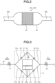
- FIG. 2 is a schematic view illustrating the first acid capturing unit 34A and the second acid capturing unit 34B included in the refrigeration cycle apparatus 1 according to the first embodiment.
- the first acid capturing unit 34A and the second acid capturing unit 34B have the same structure.
- each of the first acid capturing unit 34A and the second acid capturing unit 34B includes a container 36 in which the refrigerant flows in one direction, and the acid capturing filter 35 is provided in the container 36.
- the acid capturing filter 35 is a porous material in which, for example, activated alumina particles are formed, and captures acid due to an absorption action acted by the porous material. Consequently, the refrigeration cycle apparatus 1 is less likely to receive a damage caused by acid that is generated as a result of the refrigerant being decomposed under a high temperature environment.
- the liquid single-phase refrigerant which does not have a gas phase, passes through the acid capturing filter 35.
- a flow resistance at the time when the refrigerant passes through the interior portion of the porous material corresponding to the acid capturing filter 35 is considered, a pressure loss produced by the flow resistance at the time when the liquid single-phase refrigerant passes through the interior portion of the acid capturing filter 35, is smaller than that at the time when the gas-liquid two-phase refrigerant passes through the interior portion of the acid capturing filter 35. This is because the flow resistance at the time when the gas phase refrigerant passes through the acid capturing filter 35 is larger than the flow resistance at the time when the liquid phase refrigerant passes through the acid capturing filter 35.
- the flow resistance of the refrigerant passing through the acid capturing filter 35 is reduced. If the flow resistance is reduced, it is possible to suppress a turbulent flow of the refrigerant at the acid capturing filter 35, so that it is possible to reduce noise generated when the refrigerant passes through the acid capturing filter 35.
- the upstream side and the downstream side of the first acid capturing unit 34A in the flow channel 29a are connected via a first detour flow channel (bypass flow channel) 37A.
- the upstream side and the downstream side of the second acid capturing unit 34B in the flow channel 29a are connected via a second detour flow channel (bypass flow channel) 37B.
- a check valve 38a which allows the refrigerant to flow in only the flow direction F1 from the supercooling heat exchanger 31 side toward the shut-off valve 16 side (an indoor expansion valve 52 side that will be described later), is provided between the first acid capturing unit 34A and the shut-off valve 16, on the downstream side of the first acid capturing unit 34A in the flow direction F1 of the refrigerant at the time when the indoor unit 4 is in a cooling operation.
- the first detour flow channel 37A is provided with a check valve 38b that blocks the refrigerant, which flows toward the flow direction F1.
- a check valve 38c which allows the refrigerant to flow in only the flow direction F2 from the supercooling heat exchanger 31 side toward the outdoor expansion valve 15 side, is provided between the outdoor expansion valve 15 and the second acid capturing unit 34B, on the downstream side of the second acid capturing unit 34B in the flow direction F2 of the refrigerant at the time when the indoor unit 4 is in a heating operation.
- the second detour flow channel 37B is provided with a check valve 38d that blocks the refrigerant, which flows toward the flow direction F2.
- the two-phase refrigerant, which has passed through the outdoor expansion valve 15, passes through the second detour flow channel 37B without passing through the second acid capturing unit 34B, and the refrigerant, which has passed through the supercooling heat exchanger 31, passes through the first acid capturing unit 34A without passing through the first detour flow channel 37A.
- the refrigerant which has passed through the shut-off valve 16 passes through the first detour flow channel 37A without passing through the first acid capturing unit 34A
- the two-phase refrigerant which has passed through the supercooling heat exchanger 31
- the refrigerant passes through only one of the first acid capturing unit 34A and the second acid capturing unit 34B at the time of cooling operation and the heating operation.
- the first acid capturing unit 34A, the first detour flow channel 37A, and the check valves 38a and 38b constitute a cooling operation filter circuit 39A for removing acid included in the refrigerant at the time when the indoor unit 4 is in a cooling operation.
- the second acid capturing unit 34B, the second detour flow channel 37B, and the check valves 38c and 38d constitute a heating operation filter circuit 39B for removing acid included in the refrigerant at the time when the indoor unit 4 is in a heating operation.
- the indoor unit 4 includes an indoor heat exchanger 51, the indoor expansion valve 52, and an indoor fan 53.
- one of the refrigerant inlet/outlet ports of the indoor heat exchanger 51 is connected to the liquid pipe 6 by using an indoor unit liquid pipe 54, and the other of the refrigerant inlet/outlet ports of the indoor heat exchanger 51 is connected to the gas pipe 7 by using an indoor unit gas pipe 55.
- the indoor heat exchanger 51 performs heat exchange between indoor air, which has been taken from an inlet port (not illustrated) into the interior portion of the indoor unit 4 by the indoor fan 53, and the refrigerant.
- the indoor heat exchanger 51 functions as an evaporator in the case where the air conditioner 1 is in a cooling operation, and functions as a condenser in the case where the indoor unit 4 is in a heating operation.
- the indoor expansion valve 52 is provided in the indoor unit liquid pipe 54.
- the indoor expansion valve 52 is an electronic expansion valve, and is adjusted such that the degree of refrigerant superheat at a refrigerant outlet of the indoor heat exchanger 51 becomes a target degree of refrigerant superheat in the case where the indoor heat exchanger 51 functions as an evaporator, that is, in the case where the indoor unit 4 is in a cooling operation.
- the target degree of refrigerant superheat is the degree of refrigerant superheat for the indoor unit 4 sufficiently exhibiting a cooling operation function.
- the indoor expansion valve 52 is adjusted such that the degree of refrigerant superheat at the refrigerant outlet of the indoor heat exchanger 51 becomes a target value in the case where the indoor heat exchanger 51 functions as a condenser, that is, in the case where the indoor unit 4 is in a heating operation.
- the indoor unit 4 includes an indoor unit control circuit 60.
- the indoor unit control circuit 60 is mounted on a control substrate that is stored in an electric component box (not illustrated) of the indoor unit 4.
- the indoor unit control circuit 60 performs opening adjustment of the indoor expansion valve 52 and performs control of driving of the indoor fan 53 on the basis of the detection results detected by various sensors (not illustrated) of the indoor unit 4 or a signal sent from the outdoor unit 3.
- the control circuit, included in the refrigeration cycle apparatus 1, is constituted by the outdoor unit control circuit 30 and the indoor unit control circuit 60 described above.
- the outdoor unit control circuit 30 switches a state of the four-way valve 12 to a state indicated by the sloid line illustrated in FIG. 1 , that is, the port a and the port b of the four-way valve 12 are allowed to be communicated, and the port c and the port d are allowed to be communicated.
- the refrigerant circuit 2 enters a cooling cycle in which the outdoor heat exchanger 13 functions as a condenser and the indoor heat exchanger 51 functions as an evaporator.
- the high pressure refrigerant which is discharged from the compressor 10, flows through the discharge pipe 21a and the refrigerant pipe 21b, flows into the four-way valve 12, flows from the four-way valve 12 to the refrigerant pipe 26, the outdoor heat exchanger 13, the outdoor expansion valve 15, the second detour flow channel 37B, the supercooling heat exchanger 31, the first acid capturing unit 34A, the shut-off valve 16, and the liquid pipe 6 in this order, and then, flows into the indoor unit 4.
- the refrigerant, which flows into the indoor unit 4 flows through the indoor unit liquid pipe 54, flows into the indoor heat exchanger 51, performs heat exchange with the indoor air taken into the interior portion of the indoor unit 4 caused by a rotation of the indoor fan 53, and is then evaporated.
- the indoor heat exchanger 51 functions as an evaporator, the indoor air, which has been cooled as a result of the heat exchange performed with the refrigerant performed at the indoor heat exchanger 51, flows out from an outlet port (not illustrated) to inside a room, whereby a cooling operation is performed inside the room, in which the indoor unit 4 is installed.
- the refrigerant which flows out from the indoor heat exchanger 51, flows through the indoor unit gas pipe 55 and flows into the gas pipe 7.
- the refrigerant, which flows through the gas pipe 7, flows into the outdoor unit 3 via the shut-off valve 17.
- the refrigerant, which flows into the outdoor unit 3 flows through the outdoor unit gas pipe 28, the four-way valve 12, the refrigerant pipe 27, the accumulator 18, the intake pipe 24, and the compressor purpose accumulator 11 in this order, and is taken into the compressor 10 and is again compressed.
- a state of the four-way valve 12 is changed to the state indicated by the broken line illustrated in FIG. 1 , that is, the port a and the port d of the four-way valve 12, are allowed to be communicated, and the port b and the port d are allowed to be communicated.
- the refrigerant circuit 2 enters a heating cycle in which the outdoor heat exchanger 13 functions as an evaporator, and the indoor heat exchanger 51 functions as a condenser.
- a high temperature is about 90°C
- a medium temperature is about 40°C
- a low temperature is about 10°C.
- a pressure of the refrigerant for example, a high pressure is about 3.0 MPa, a medium pressure is about 2.8 MPa, and a low pressure is about 0.9 MPa.
- a refrigerant at medium temperature and high pressure flows into the inlet of the outdoor expansion valve 15, and a refrigerant at medium temperature and high pressure flows out from the outlet of the outdoor expansion valve 15.
- a refrigerant at high pressure flows into the supercooling heat exchanger 31 that is located on the downstream side of the outdoor expansion valve 15 in the flow direction F1 of the refrigerant, and a liquid single-phase refrigerant flows out from the supercooling heat exchanger 31.
- the outdoor unit control circuit 30, included in the refrigeration cycle apparatus 1 performs control such that the degree of opening of the outdoor expansion valve 15 is fully opened. That is, the outdoor expansion valve 15 does not decompress the refrigerant at the time of cooling operation.
- a refrigerant at medium temperature and medium pressure flows into the inlet of the indoor expansion valve 52, and a refrigerant at low temperature and low pressure flows out from the outlet of the indoor expansion valve 52.
- the indoor unit control circuit 60 included in the refrigeration cycle apparatus 1, decompresses the refrigerant up to an evaporation temperature in which appropriate evaporation capacity is able to obtain in the indoor heat exchanger 51, and controls a flow rate of the refrigerant.
- the indoor unit control circuit 60 performs control such that the degree of refrigerant superheat at the outlet of the indoor heat exchanger 51 (a value obtained by subtracting a temperature of the refrigerant at the inlet of the indoor heat exchanger 51 from a temperature of the refrigerant at the outlet of the indoor heat exchanger 51 (evaporator)) is maintained at a predetermined target value.
- a refrigerant at medium temperature and high pressure flows into the inlet of the indoor expansion valve 52, and a refrigerant at medium temperature and high pressure flows out from the outlet of the indoor expansion valve 52.
- a refrigerant at high pressure flows into the supercooling heat exchanger 31 that is located on the downstream side of the indoor expansion valve 52 in the flow direction F2 of the refrigerant, and a liquid single-phase refrigerant flows out from the supercooling heat exchanger 31.
- the indoor unit control circuit 60 performs control such that the degree of refrigerant supercooling (a value obtained by subtracting a temperature of the refrigerant at the outlet of the indoor heat exchanger 51 (condenser) from a high pressure saturation temperature) is maintained at a predetermined target value.
- a refrigerant at medium temperature and medium pressure flows into the inlet of the outdoor expansion valve 15, and a refrigerant at low temperature and low pressure flows out from the outlet of the outdoor expansion valve 15.
- the outdoor unit control circuit 30, included in the refrigeration cycle apparatus decompresses the refrigerant up to the evaporation temperature in which appropriate evaporation capacity is able to be obtained in the outdoor heat exchanger 13 by adjusting the degree of opening of the outdoor expansion valve 15, and controls a flow rate of the refrigerant.
- the refrigeration cycle apparatus 1 is provided with the refrigerant circuit 2 having the flow channel 29a through which the liquid single-phase refrigerant flows, and the acid capturing filter 35 that is provided in the flow channel 29a and that captures acid included in a flowing refrigerant.
- the pressure loss which is caused by the flow resistance at the time when the refrigerant passes through the acid capturing filter 35, is smaller than that at the time when the gas-liquid two-phase refrigerant passes through the acid capturing filter 35. Consequently, it is possible to suppress the pressure loss of the refrigerant, which passes through the acid capturing filter 35, and it is thus possible to suppress a reduction in refrigeration capacity of the refrigeration cycle apparatus 1 that includes the acid capturing filter 35.
- a flow resistance at the time when a liquid single-phase refrigerant passes through the acid capturing filter 35 is smaller than that at the time when a gas-liquid two-phase refrigerant passes through the acid capturing filter 35. If the flow resistance is reduced, it is possible to suppress the turbulent flow of the refrigerant at the acid capturing filter 35, so that it is possible to reduce noise generated when the refrigerant passes through the acid capturing filter 35.
- the refrigerant circuit 2, included in the refrigeration cycle apparatus 1 according to the first embodiment is provided with the supercooling heat exchanger 31 that allows a gas-liquid two-phase refrigerant to be changed to a liquid single-phase supercooling refrigerant on the upstream side of the flow direction of the refrigerant with respect to the acid capturing filter 35.
- the supercooling heat exchanger 31 that allows a gas-liquid two-phase refrigerant to be changed to a liquid single-phase supercooling refrigerant on the upstream side of the flow direction of the refrigerant with respect to the acid capturing filter 35.
- the acid capturing filter 35 is disposed on the downstream side of the supercooling heat exchanger 31, so that, even if an air bubbleis generated, what is called flash-gas is generated in the refrigerant as a result of some of the refrigerant being evaporated in accordance with, for example, a pressure loss produced in the outdoor unit liquid pipe 29, the refrigerant is subjected to supercooling in the supercooling heat exchanger 31; therefore, it is possible to appropriately send the liquid single-phase refrigerant to the acid capturing filter 35.
- the acid capturing filter 35 included in the refrigeration cycle apparatus 1 according to the first embodiment, includes the acid capturing filter 35 that is provided in the first acid capturing unit 34A and that functions as the first filter member, and includes the acid capturing filter 35 that is provided in the second acid capturing unit 34B and that functions as the second filter member.
- the refrigerant circuit 2 is provided with, in the flow directions F1 and F2 of the refrigerant, the first detour flow channel 37A that connects the upstream side of the first acid capturing unit 34A and the downstream side of the first acid capturing unit 34A, and the second detour flow channel 37B that connects the upstream side of the second acid capturing unit 34B and the downstream side of the second acid capturing unit 34B, and the refrigerant passes only one of the first acid capturing unit 34A and the second acid capturing unit 34B at the time of heating operation and the cooling operation performed by the indoor unit 4.
- the refrigerant passes through the acid capturing filter 35 on the downstream side of the supercooling heat exchanger 31. Furthermore, the refrigerant passes through only one of the first acid capturing unit 34A and the second acid capturing unit 34B, so that the effect of the flow resistance, caused by the acid capturing filter 35 at the time of operation, is made by only one filter, it is thus possible to suppress a reduction in the refrigeration capacity of the refrigeration cycle apparatus 1.
- the lubricating oil 9, which is included in the refrigerant it is possible to prevent the lubricating oil 9, which is included in the refrigerant, from being retained in the acid capturing filter 35, so that it is possible to suppress a decrease in an amount of the lubricating oil 9, which is contained in the compressor 10, and it is thus possible to appropriately maintain an operation of the compressor 10 using the lubricating oil 9.
- the lubricating oil 9 may be separated and retained in the acid capturing filter 35; however, in the case of the liquid single-phase refrigerant, the lubricating oil 9 passes through the acid capturing filter 35 together with the liquid refrigerant, so that the lubricating oil 9 is not retained in the acid capturing filter 35.
- the supercooling heat exchanger 31 is used to send the liquid single-phase refrigerant to the flow channel 29a; however, instead of the supercooling heat exchanger 31, a gas-liquid separator, which separates a refrigerant into a liquid single-phase refrigerant and a gas single-phase refrigerant, may be used.
- a gas-liquid separator which separates a refrigerant into a liquid single-phase refrigerant and a gas single-phase refrigerant, may be used.
- the gas-liquid separator is used instead of the supercooling heat exchanger 31 in the refrigerant circuit 2 illustrated in FIG.
- the liquid single-phase refrigerant is sent to the flow channel 29a after passing through the gas-liquid separator, and the gas single-phase refrigerant is sent from the gas-liquid separator to the refrigerant pipe 27 by passing through the refrigerant pipe 33.
- the gas-liquid separator tends to exhibit high enthalpy of the liquid single-phase refrigerant, which flows out from the gas-liquid separator, as compared to the case where the supercooling heat exchanger 31 is used.
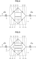
- FIG. 3 is a schematic view illustrating the main part of a refrigeration cycle apparatus according to a second embodiment.
- the second embodiment is different from the first embodiment in that a bridge circuit, which is provided with a single acid capturing unit, is included.
- the refrigerant circuit 2 included in the refrigeration cycle apparatus according to the second embodiment includes a bridge circuit 61 that includes the supercooling heat exchanger 31 and an acid capturing unit 34.
- the bridge circuit 61 is provided with a single acid capturing unit 34, and in which, as will be described later, a refrigerant flows only one direction with respect to the acid capturing unit 34.
- the acid capturing unit 34 has the same configuration as that of the first acid capturing unit 34A and the second acid capturing unit 34B according to the first embodiment, and includes the acid capturing filter 35.
- the refrigerant pipe 33 which sends a gas refrigerant to the refrigerant pipe 27, is connected to the low pressure side flow channel of the supercooling heat exchanger 31 (see FIG. 1 ).
- the refrigerant pipe 33 allows some of the refrigerant, which flows between the supercooling heat exchanger 31 and the acid capturing unit 34, to flow into the refrigerant pipe 27, which extends from the port c of the four-way valve 12 to the accumulator 18, via the supercooling expansion valve 32 and the low pressure side flow channel.
- the portion A including the bridge circuit 61 that includes the supercooling heat exchanger 31 and the acid capturing unit 34, has the same configuration as the portion A that includes the supercooling heat exchanger 31, the first acid capturing unit 34A, and the second acid capturing unit 34B illustrated in FIG. 1 .
- the bridge circuit 61 includes a first flow channel 61a, a second flow channel 61b, a third flow channel 61c, a fourth flow channel 61d, and a fifth flow channel 61e, and a check valve 62 is provided in each of the first flow channel 61a, the second flow channel 61b, the fourth flow channel 61d, and the fifth flow channel 61e except for the third flow channel 61c.
- the check valve 62 which is provided in the first flow channel 61a, regulates the flow of the refrigerant flowing from the supercooling heat exchanger 31 toward the outdoor expansion valve 15.
- the check valve 62 which is provided in the second flow channel 61b, regulates the flow of the refrigerant flowing from the outdoor expansion valve 15 toward the acid capturing unit 34.
- the check valve 62 which is provided in the fourth flow channel 61d, regulates the flow of the refrigerant flowing from the supercooling heat exchanger 31 toward the indoor expansion valve 52.
- the check valve 62 which is provided in the fifth flow channel 61e, regulates the flow of the refrigerant flowing from the indoor expansion valve 52 toward the acid capturing unit 34.
- the supercooling heat exchanger 31 and the acid capturing unit 34 are disposed in this order along the one direction.
- one section in the flow direction of the refrigerant on the downstream side of the supercooling heat exchanger 31, corresponds to the flow channel 29a in which the liquid single-phase refrigerant flows.
- the liquid single-phase refrigerant, which has passed through the supercooling heat exchanger 31, flows into the acid capturing filter 35 of the acid capturing unit 34.
- the refrigerant which flows from the outdoor expansion valve 15 into the bridge circuit 61, flows through the first flow channel 61a, the third flow channel 61c, and the fifth flow channel 61e in this order in the flow direction F1 of the refrigerant and is sent to the indoor expansion valve 52.
- the refrigerant which flows from the indoor expansion valve 52 to the bridge circuit 61, flows through the fourth flow channel 61d, the third flow channel 61c, and the second flow channel 61b in this order in the flow direction F2 of the refrigerant and is sent to the outdoor expansion valve 15.
- the refrigeration cycle apparatus includes the bridge circuit 61, so that it is possible to compactly constitute the refrigerant circuit 2 by using the single piece of the acid capturing unit 34 without using the two acid capturing units of the first acid capturing unit 34A and the second acid capturing unit 34B as described in the first embodiment.
- the second embodiment similar to the first embodiment, as a result of the liquid single-phase refrigerant passing through the acid capturing filter 35, it is possible to suppress the pressure loss of the refrigerant, which passes through the acid capturing filter 35, as compared to the case where the gas-liquid two-phase refrigerant passing through the acid capturing filter 35, so that it is possible to suppress a decrease in the refrigeration capacity of the refrigeration cycle apparatus that includes the acid capturing filter 35. Furthermore, in also the second embodiment, as compared to the case where the gas-liquid two-phase refrigerant passes through the acid capturing filter 35, it is possible to reduce noise generated at the time when the liquid single-phase refrigerant passes through the acid capturing filter 35.
- FIG. 4 is a schematic view illustrating the main part of the refrigeration cycle apparatus according to a third embodiment.
- the third embodiment is different from the second embodiment in that the bridge circuit 61, which is provided with a gas-liquid separator, is included.
- the refrigeration cycle apparatus includes the bridge circuit 61 that includes a gas-liquid separator 64 and the acid capturing unit 34.
- the gas-liquid separator 64 is used instead of the supercooling heat exchanger 31 according to the second embodiment.
- the gas-liquid separator 64 is disposed, in the upstream side of the acid capturing unit 34, such that a liquid flow outlet is connected on the acid capturing unit 34 side.
- the gas-liquid separator 64 separates the liquid single-phase refrigerant from the gas-liquid two-phase refrigerant, and sends the liquid single-phase refrigerant to the acid capturing filter 35.
- the refrigerant pipe 33 which sends the separated gas phase refrigerant (gas refrigerant) to the refrigerant pipe 27 (see FIG. 1 ), is connected to a gas flow outlet of the gas-liquid separator 64.
- the refrigerant pipe 33 allows some of the refrigerant, which flows between the gas-liquid separator 64 and the acid capturing unit 34, to flow into the refrigerant pipe 27, whichextends from the port c of the four-way valve 12 to the accumulator 18, via a bypass expansion valve (corresponds to the supercooling expansion valve 32 according to the first embodiment).
- one section on the downstream side of the gas-liquid separator 64 in the flow direction of the refrigerant corresponds to the flow channel in which the liquid single-phase refrigerant that has been separated from the gas phase refrigerant flows.
- the liquid single-phase refrigerant which is sent from the gas-liquid separator 64, passes through the acid capturing filter 35 of the acid capturing unit 34.
- the portion A including the bridge circuit 61 that includes the gas-liquid separator 64 and the acid capturing unit 34, has the same configuration and function as the portion A, including the supercooling heat exchanger 31, the first acid capturing unit 34A, and the second acid capturing unit 34B illustrated in FIG. 1 .
- the refrigeration cycle apparatus includes the bridge circuit 61, so that it is possible to compactly constitute the refrigerant circuit 2 without using the two acid capturing units of the first acid capturing unit 34A and the second acid capturing unit 34B as described in the first embodiment.
- the third embodiment it is possible to send the liquid single-phase refrigerant that has been separated from the gas-liquid separator 64 to the acid capturing unit 34, so that, similar to the first embodiment, it is possible to suppress the pressure loss of the refrigerant, which passes through the acid capturing filter 35, as compared to the case where the gas-liquid two-phase refrigerant passes through the acid capturing filter 35, and it is thus possible to suppress a decrease in the refrigeration capacity of the refrigeration cycle apparatus that includes the acid capturing filter 35. Furthermore, in also the second embodiment, it is possible to reduce noise generated when the liquid single-phase refrigerant passes through the acid capturing filter 35 as compared to the case in which the gas-liquid two-phase refrigerant passes through the acid capturing filter 35.
- the gas-liquid separator 64 may be used, for example, the gas-liquid separator 64 may be provided on each of the upstream side of the first acid capturing unit 34A in the flow direction F1 of the refrigerant and the upstream side of the second acid capturing unit 34B in the flow direction F2 of the refrigerant.
- the two gas-liquid separators 64 are disposed such that the refrigerant is able to detour one of the gas-liquid separators 64 and the first acid capturing unit 34A by the first detour flow channel 37A, and are disposed such that the refrigerant is able to detour the other one of the gas-liquid separators 64 and the second acid capturing unit 34B by the second detour flow channel 37B.
- the one gas-liquid separator 64 is disposed such that the liquid flow outlet is connected to the first acid capturing unit 34A side, whereas the other gas-liquid separator 64 is disposed such that the liquid flow outlet is connected to the second acid capturing unit 34B side.
- FIG. 5 is a schematic view illustrating the main part of a refrigeration cycle apparatus according to a fourth embodiment.
- the fourth embodiment is different from the second embodiment in that a receiver 65 is added to the bridge circuit 61 that is provided with the supercooling heat exchanger.
- the refrigeration cycle apparatus includes the bridge circuit 61 that includes the receiver 65, the supercooling heat exchanger 31, and the acid capturing unit 34.
- the receiver 65 is disposed on the upstream side of the supercooling heat exchanger 31 in the flow direction of the refrigerant, which flows through the third flow channel 61c, and a liquid single-phase refrigerant, which is separated by the receiver 65, is sent to the supercooling heat exchanger 31.
- the refrigerant pipe 33 which sends a gas refrigerant to the refrigerant pipe 27 (see FIG. 1 ), is connected to the low pressure side flow channel of the supercooling heat exchanger 31.
- the refrigerant pipe 33 allows some of the refrigerant, which flows between the supercooling heat exchanger 31 and the acid capturing unit 34, to flow into the refrigerant pipe 27, which extends from the port c of the four-way valve 12 to the accumulator 18, via the supercooling expansion valve 32 and the low pressure side flow channel.
- the portion A which includes the bridge circuit 61 that includes the receiver 65, the supercooling heat exchanger 31, and the acid capturing unit 34, has the same configuration as the portion A, which includes the supercooling heat exchanger 31, the first acid capturing unit 34A, and the second acid capturing unit 34B illustrated in FIG. 1 .
- the refrigeration cycle apparatus includes, on the upstream side of the supercooling heat exchanger 31, the receiver 65 that has a function of adjusting an amount of the refrigerant, which flows through the refrigerant circuit 2, so that it is also possible to cope with a variation in an environment load.
- the fourth embodiment similar to the first embodiment, as a result of the liquid single-phase refrigerant passing through the acid capturing filter 35, it is possible to suppress a pressure loss of the refrigerant, which passes through the acid capturing filter 35, as compared to a case where the gas-liquid two-phase refrigerant passes through the acid capturing filter 35, so that it is possible to suppress a reduction in the refrigeration capacity of the refrigeration cycle apparatus that includes the acid capturing filter 35. In addition, in also the fourth embodiment, it is possible to reduce noise generated when the liquid single-phase refrigerant passes through the acid capturing filter 35 as compared to a case where the gas-liquid two-phase refrigerant passes through the acid capturing filter 35.
- the receiver 65 may be used, and the receiver 65 may be provided, for example, on one of the upstream side of the first acid capturing unit 34A in the flow direction F1 of the refrigerant and the upstream side of the second acid capturing unit 34B in the flow direction F2 of the refrigerant.
Landscapes
- Engineering & Computer Science (AREA)
- Physics & Mathematics (AREA)
- Mechanical Engineering (AREA)
- Thermal Sciences (AREA)
- General Engineering & Computer Science (AREA)
- Chemical & Material Sciences (AREA)
- Analytical Chemistry (AREA)
- Power Engineering (AREA)
- Compression-Type Refrigeration Machines With Reversible Cycles (AREA)
Abstract
Description
- The present invention relates to a refrigeration cycle apparatus.
- In refrigeration cycle apparatuses, it has been proposed to use an R466A refrigerant as a refrigerant with a low global warming potential (GWP) (Patent Literature 1). The R466A refrigerant is made of mixed refrigerants containing three components of an R32 refrigerant, an R125 refrigerant, and trifluoroiodomethane (CF3I), and is decomposed under a high temperature environment to generate acid, so that a refrigeration cycle apparatus may be damaged as a result of corrosion of metal parts, such as pipes, constituting a refrigerant circuit, caused by acid. Accordingly, as a related technology, in some cases, an acid capturing filter, which captures acid generated from the R466A refrigerant, is provided in the refrigerant circuit (Patent Literature 2).
-
- Patent Literature 1:
Japanese Laid-open Patent Publication No. 2020-34261 - Patent Literature 2:
Japanese Laid-open Patent Publication No. 2018-96571 - In the related technology described above, the acid capturing filter is disposed between an expansion valve and an evaporator, or, between an expansion valve and a condenser, and a gas-liquid two-phase refrigerant passes through the acid capturing filter. The acid capturing filter has a structure in which a flow resistance is large in order to increase a contact area with the refrigerant. As a result, there is a problem in that a pressure loss is generated when the gas-liquid two-phase refrigerant passes through the acid capturing filter, and the refrigeration capacity of the refrigeration cycle apparatus is decreased.
- Accordingly, the disclosed technology has been conceived in light of the circumstances described above, and an object thereof is to provide a refrigeration cycle apparatus that is able to suppress a pressure loss of a refrigerant, which passes through a filter member, and that is able to suppress a decrease in refrigeration capacity of the refrigeration cycle apparatus that includes the filter member.
- According to an aspect of an embodiments in the present application, a refrigeration cycle apparatus includes: a refrigerant circuit that includes a flow channel through which a refrigerant in a liquid single-phase state flows; and a filter member that is provided in the flow channel and that captures acid contained in the refrigerant, which passes through the flow channel. Advantageous Effects of Invention
- According to an aspect of an embodiment of a refrigeration cycle apparatus disclosed in the present application, it is possible to suppress a pressure loss of the refrigerant, which passes through the filter member, and a decrease in refrigeration capacity of the refrigeration cycle apparatus that includes the filter member.
-
-
FIG. 1 is a schematic view illustrating the entire of a refrigeration cycle apparatus according to a first embodiment. -
FIG. 2 is a schematic view illustrating a first acid capturing unit and a second acid capturing unit included in the refrigeration cycle apparatus according to the first embodiment. -
FIG. 3 is a schematic view illustrating the main part of a refrigeration cycle apparatus according to a second embodiment. -
FIG. 4 is a schematic view illustrating the main part of a refrigeration cycle apparatus according to a third embodiment. -
FIG. 5 is a schematic view illustrating the main part of a refrigeration cycle apparatus according to a fourth embodiment. - Preferred embodiments of a refrigeration cycle apparatus, disclosed in the present invention, will be described in detail below with reference to the accompanying drawings. Furthermore, the refrigeration cycle apparatus, disclosed in the present invention, is not limited by the embodiments described below.
- As a refrigeration cycle apparatus according to an embodiment, an air conditioning apparatus is used as an example in which one indoor unit is connected to one outdoor unit, and the indoor unit is configured to be able to perform a cooling operation or a heating operation will be described.
FIG. 1 is a schematic view illustrating the entire of the refrigeration cycle apparatus according to the first embodiment. - First, a refrigerant that is used in a
refrigeration cycle apparatus 1 according to the embodiment, will be described. In therefrigeration cycle apparatus 1 according to the embodiment, an R466A refrigerant is used as a refrigerant. The R466A refrigerant is a mixed refrigerant containing three components of an R32 refrigerant, an R125 refrigerant, and trifluoroiodomethane (CF3I). In some cases, after the R466A refrigerant is compressed by a compression unit in a compressor, the R466A refrigerant is decomposed under a high temperature environment and generates acid, so that the refrigeration cycle apparatus may be damaged as a result of corrosion of a refrigerant circuit caused by acid. Accordingly, in therefrigeration cycle apparatus 1 according to the embodiment, acid contained in the refrigerant is captured by a firstacid capturing unit 34A and a secondacid capturing unit 34B, which will be described later, and acid is removed from the refrigerant, thereby suppressing the damage of therefrigeration cycle apparatus 1. - Furthermore, the refrigerant is not limited to the R466A refrigerant, and another refrigerant may be used as long as a refrigerant may generate acid. For example, in a refrigerant containing hydrofluoroolefin (HFO), a vapor pressure [kPa] of the refrigerant is low, and an area, in which a negative pressure that is lower than the atmospheric pressure, is likely to be generated during an operation in the refrigerant circuit, so that, in a section in which a refrigerant at high pressure is decompressed, oxygen is likely to flow into the refrigerant as a result of absorbing outside air into the refrigerant circuit, and thus, acid is likely to be generated because the refrigerant is subjected to oxidative decomposition. In also the case where such a refrigerant is used, the first embodiment may be applied, and, similar to the first embodiment, the effects described later is obtained.
- As illustrated in
FIG. 1 , therefrigeration cycle apparatus 1 includes a refrigerant circuit 2 in which a refrigerant circulates, anoutdoor unit 3 and anindoor unit 4 that are provided in the refrigerant circuit 2. InFIG. 1 , the flow of the refrigerant in the case where a cooling operation is performed in theindoor unit 4, is indicated by arrows. The refrigerant circuit 2 includes aliquid pipe 6 and agas pipe 7 that connect theoutdoor unit 3 and theindoor unit 4. One end of theliquid pipe 6 is connected to a shut-off valve (liquid two-way valve) 16 of theoutdoor unit 3, and the other end thereof is connected to theindoor unit 4. One end of thegas pipe 7 is connected to a shut-off valve (gas three-way valve) 17 of theoutdoor unit 3, and the other end thereof is connected to theindoor unit 4. - First, the
outdoor unit 3 will be described. Theoutdoor unit 3 includes acompressor 10, anaccumulator 11, a four-way valve 12, anoutdoor heat exchanger 13, anoutdoor fan 14, anoutdoor expansion valve 15, the shut-offvalve 16 to which one end of theliquid pipe 6 is connected, the shut-offvalve 17 to which one end of thegas pipe 7 is connected, and anaccumulator 18 that is a refrigerant retainer. - The
compressor 10 is a rotary compressor with a variable capacity type capable of changing its operational capacity as a result of being driven by a motor (not illustrated) whose rotation speed is controlled by an inverter. The interior portion of thecompressor 10 retains thereinrefrigerator oil 9 functioning as lubricating oil that lubricates a sliding portion (not illustrated). The refrigerant discharge side of thecompressor 10 is connected to, via adischarge pipe 21a, anoil separator 22 that separates therefrigerator oil 9 from the refrigerant, which has been discharged from thecompressor 10. Furthermore, theoil separator 22 is connected, via arefrigerant pipe 21b, a port a of a four-way valve 12 that will be described later, and the refrigerant separated from therefrigerator oil 9 is sent to the four-way valve 12. Furthermore, theoil separator 22 is connected to arefrigerant pipe 21c that is connected to a refrigerant inflow side of theaccumulator 18, and therefrigerator oil 9, which is separated from the refrigerant, is sent to thecompressor purpose accumulator 11 together with the gas refrigerant that is sent from theaccumulator 18. Therefrigerant pipe 21c is provided with apressure reduction valve 23 that is used to decompress therefrigerator oil 9, which is received from theoil separator 22. In addition, therefrigerant pipe 21c may be provided with a capillary tube (not illustrated) instead of thepressure reduction valve 23. A refrigerant intake side of thecompressor 10 is connected to the refrigerant outflow side of theaccumulator 18 and therefrigerant pipe 21c via anintake pipe 24. In this way, thecompressor 10 is connected to the refrigerant circuit 2 in which the refrigerant is filled. - The four-
way valve 12 is a switching valve for switching a flow direction of the refrigerant flows, and includes four ports a, b, c, and d. As described above, the port a is connected to the refrigerant discharge side of thecompressor 10 by using thedischarge pipe 21a via theoil separator 22 that is connected by therefrigerant pipe 21b. The port b is connected to one of the refrigerant inlet/outlet ports of theoutdoor heat exchanger 13 by using arefrigerant pipe 26. The other of the refrigerant inlet/outlet ports of theoutdoor heat exchanger 13 is connected to theliquid pipe 6 by using an outdoor unitliquid pipe 29. The port c is connected to the refrigerant inflow side of theaccumulator 18 via arefrigerant pipe 27. Furthermore, the port d is connected to the shut-offvalve 17 by using an outdoorunit gas pipe 28. - The
outdoor heat exchanger 13 performs heat exchange between the outside air that is brought into the interior portion of theoutdoor unit 3 by theoutdoor fan 14 and the refrigerant. As described above, the one refrigerant inlet/outlet port of theoutdoor heat exchanger 13 is connected to the port b of the four-way valve 12 by using therefrigerant pipe 26, and the other refrigerant inlet/outlet port is connected to the shut-offvalve 16 via the outdoor unitliquid pipe 29. - The
outdoor expansion valve 15 is provided in the outdoor unitliquid pipe 29. Theoutdoor expansion valve 15 is an electronic expansion valve, and adjusts an amount of the refrigerant flowing into theoutdoor heat exchanger 13 or an amount of the refrigerant flowing out from theoutdoor heat exchanger 13 as a result of adjustment of the degree of opening of theoutdoor expansion valve 15. The degree of opening of theoutdoor expansion valve 15 is fully opened in a case in which therefrigeration cycle apparatus 1 performs a cooling operation. Furthermore, in a case in which therefrigeration cycle apparatus 1 performs a heating operation, by controlling the degree of opening of theoutdoor expansion valve 15 in accordance with a discharge temperature of the refrigerant received from thecompressor 10, adjustment is performed such that the discharge temperature of the refrigerant does not exceed an upper limit of thecompressor 10 at the time of operation. - The refrigerant inflow side of the
accumulator 18 is connected to the port c of the four-way valve 12 via therefrigerant pipe 27, and the refrigerant outflow side of theaccumulator 18 is connected to the refrigerant intake side of thecompressor 10 via theintake pipe 24. In this way, theaccumulator 18 is connected to the refrigerant circuit 2 and thecompressor 10. Theaccumulator 18 separates the refrigerant flowing from therefrigerant pipe 27 into the interior portion of theaccumulator 18 into a gas refrigerant and a liquid refrigerant. The separated gas refrigerant is taken into thecompressor 10 via thecompressor purpose accumulator 11. - Furthermore, the
outdoor unit 3 includes an outdoorunit control circuit 30 that functions as a control unit. Although not illustrated, the outdoorunit control circuit 30 is mounted on a control substrate that is stored in an electric component box (not illustrated) of theoutdoor unit 3. The outdoorunit control circuit 30 performs control of driving of thecompressor 10 and theoutdoor fan 14, on the basis of a detection result and a control signal that are detected by various sensors (not illustrated) of theoutdoor unit 3. Furthermore, the outdoorunit control circuit 30 performs switching control of the four-way valve 12 on the basis of the detection result and the control signal detected by the various sensors of theoutdoor unit 3, and adjusts the degree of opening of theoutdoor expansion valve 15. - Furthermore, in the outdoor unit
liquid pipe 29 that is located between theoutdoor heat exchanger 13 and the shut-offvalve 16, the refrigerant circuit 2 is provided with asupercooling heat exchanger 31, which functions as a supercooler that allows the gas-liquid two-phase refrigerant to be changed to a liquid single-phase supercooling refrigerant. In addition, the refrigerant circuit 2 includes arefrigerant pipe 33 that allows some of the refrigerant, which flows between the supercoolingheat exchanger 31 and the shut-offvalve 16, to flow into therefrigerant pipe 27, which extends from the port c of the four-way valve 12 to theaccumulator 18, via asupercooling expansion valve 32. The supercoolingheat exchanger 31 includes a high pressure side flow channel and a low pressure side flow channel that are not illustrated. The refrigerant, which flows out from theoutdoor expansion valve 15, flows into the high pressure side flow channel at the time when theindoor unit 4 is in a cooling operation. The refrigerant, which flows into the high pressure side flow channel, is subjected to heat exchange with the refrigerant that is present in the low pressure side flow channel, and then flows out to the shut-offvalve 16 side. The low pressure side flow channel is provided in therefrigerant pipe 33, and the refrigerant, which flows out from the supercoolingexpansion valve 32, flows into the low pressure side flow channel. The refrigerant, which flows into the low pressure side flow channel, is subjected to heat exchange with the refrigerant that is present in the high pressure side flow channel, and then, flows out to therefrigerant pipe 27 side. In addition, in a flow direction F2 of the refrigerant at the time when theindoor unit 4 is in a heating operation, asupercooling expansion valve 32 is provided in the outdoor unitliquid pipe 29 at a position closer to the upstream side than the supercoolingheat exchanger 31. With this configuration described above, the downstream side of thesupercooling heat exchanger 31, which is provided in the outdoor unitliquid pipe 29, becomes aflow channel 29a through which the liquid single-phase refrigerant flows. - In this way, the refrigerant circuit 2 includes the
flow channel 29a through which the liquid single-phase refrigerant flows, and theflow channel 29a corresponds to one section of the outdoor unitliquid pipe 29 in the refrigerant circuit 2. In the case where a cooling operation is performed by theindoor unit 4, the section, between the supercoolingheat exchanger 31 and the shut-offvalve 16 in the outdoor unitliquid pipe 29, is theflow channel 29a through which the liquid single-phase refrigerant. In the case where a heating operation is performed by theindoor unit 4, the section, between the supercoolingheat exchanger 31 and theoutdoor expansion valve 15 in the outdoor unitliquid pipe 29, is theflow channel 29a through which the liquid single-phase refrigerant flows. - In addition, as illustrated in
FIG. 1 , theflow channel 29a of the refrigerant circuit 2 is provided with the firstacid capturing unit 34A and the secondacid capturing unit 34B each having anacid capturing filter 35 that functions as a filter member and that captures acid included in the passing refrigerant. The filter member includes theacid capturing filter 35, which functions as the first filter member for the firstacid capturing unit 34A, and theacid capturing filter 35, which functions as the second filter member for the secondacid capturing unit 34B. - The first
acid capturing unit 34A is disposed on the downstream side of thesupercooling heat exchanger 31, that is, disposed between the supercoolingheat exchanger 31 and the shut-offvalve 16, in the flow direction F1 of the refrigerant at the time when theindoor unit 4 is in a cooling operation. The secondacid capturing unit 34B is disposed on the downstream side of thesupercooling heat exchanger 31, that is, disposed between the supercoolingheat exchanger 31 and theoutdoor expansion valve 15, in the flow direction F2 of the refrigerant at the time when theindoor unit 4 is in a heating operation. - In other words, the
flow channel 29a in the refrigerant circuit 2 is provided with the supercoolingheat exchanger 31, which allows the gas-liquid two-phase refrigerant to be changed to the liquid single-phase supercooling refrigerant, on the upstream side of the flow direction F1 of the refrigerant at the time when theindoor unit 4 is in a cooling operation with respect to the firstacid capturing unit 34A, which includes theacid capturing filter 35. Furthermore, theflow channel 29a in the refrigerant circuit 2 is provided with the supercoolingheat exchanger 31, which allows the gas-liquid two-phase refrigerant to be changed to the liquid single-phase supercooling refrigerant, on the upstream side of the flow direction F2 of the refrigerant at the time when theindoor unit 4 is in a heating operation with respect to the secondacid capturing unit 34B, which includes theacid capturing filter 35. -
FIG. 2 is a schematic view illustrating the firstacid capturing unit 34A and the secondacid capturing unit 34B included in therefrigeration cycle apparatus 1 according to the first embodiment. The firstacid capturing unit 34A and the secondacid capturing unit 34B have the same structure. As illustrated inFIG. 2 , each of the firstacid capturing unit 34A and the secondacid capturing unit 34B includes acontainer 36 in which the refrigerant flows in one direction, and theacid capturing filter 35 is provided in thecontainer 36. Theacid capturing filter 35 is a porous material in which, for example, activated alumina particles are formed, and captures acid due to an absorption action acted by the porous material. Consequently, therefrigeration cycle apparatus 1 is less likely to receive a damage caused by acid that is generated as a result of the refrigerant being decomposed under a high temperature environment. - In the first embodiment, the liquid single-phase refrigerant, which does not have a gas phase, passes through the
acid capturing filter 35. When a flow resistance at the time when the refrigerant passes through the interior portion of the porous material corresponding to theacid capturing filter 35, is considered, a pressure loss produced by the flow resistance at the time when the liquid single-phase refrigerant passes through the interior portion of theacid capturing filter 35, is smaller than that at the time when the gas-liquid two-phase refrigerant passes through the interior portion of theacid capturing filter 35. This is because the flow resistance at the time when the gas phase refrigerant passes through theacid capturing filter 35 is larger than the flow resistance at the time when the liquid phase refrigerant passes through theacid capturing filter 35. In this way, it is possible to suppress the pressure loss due to the firstacid capturing unit 34A and the secondacid capturing unit 34B as a result of a decrease in the flow resistance at the time when the liquid single-phase refrigerant passes through the acid capturing filter, so that it is possible to suppress a decrease in refrigeration capacity of therefrigeration cycle apparatus 1 even in a case of the structure that uses theacid capturing filter 35. - Furthermore, the flow resistance of the refrigerant passing through the
acid capturing filter 35, is reduced. If the flow resistance is reduced, it is possible to suppress a turbulent flow of the refrigerant at theacid capturing filter 35, so that it is possible to reduce noise generated when the refrigerant passes through theacid capturing filter 35. - Furthermore, the upstream side and the downstream side of the first
acid capturing unit 34A in theflow channel 29a are connected via a first detour flow channel (bypass flow channel) 37A. Similarly to this, the upstream side and the downstream side of the secondacid capturing unit 34B in theflow channel 29a are connected via a second detour flow channel (bypass flow channel) 37B. - A
check valve 38a, which allows the refrigerant to flow in only the flow direction F1 from the supercoolingheat exchanger 31 side toward the shut-offvalve 16 side (anindoor expansion valve 52 side that will be described later), is provided between the firstacid capturing unit 34A and the shut-offvalve 16, on the downstream side of the firstacid capturing unit 34A in the flow direction F1 of the refrigerant at the time when theindoor unit 4 is in a cooling operation. The firstdetour flow channel 37A is provided with acheck valve 38b that blocks the refrigerant, which flows toward the flow direction F1. - A
check valve 38c, which allows the refrigerant to flow in only the flow direction F2 from the supercoolingheat exchanger 31 side toward theoutdoor expansion valve 15 side, is provided between theoutdoor expansion valve 15 and the secondacid capturing unit 34B, on the downstream side of the secondacid capturing unit 34B in the flow direction F2 of the refrigerant at the time when theindoor unit 4 is in a heating operation. The seconddetour flow channel 37B is provided with acheck valve 38d that blocks the refrigerant, which flows toward the flow direction F2. - Therefore, in the case where the
indoor unit 4 is in a cooling operation, the two-phase refrigerant, which has passed through theoutdoor expansion valve 15, passes through the seconddetour flow channel 37B without passing through the secondacid capturing unit 34B, and the refrigerant, which has passed through the supercoolingheat exchanger 31, passes through the firstacid capturing unit 34A without passing through the firstdetour flow channel 37A. Furthermore, in the case where theindoor unit 4 is in a heating operation, the refrigerant, which has passed through the shut-offvalve 16, passes through the firstdetour flow channel 37A without passing through the firstacid capturing unit 34A, the two-phase refrigerant, which has passed through the supercoolingheat exchanger 31, passes through the secondacid capturing unit 34B without passing through the seconddetour flow channel 37B. In this way, the refrigerant passes through only one of the firstacid capturing unit 34A and the secondacid capturing unit 34B at the time of cooling operation and the heating operation. - In this way, the first
acid capturing unit 34A, the firstdetour flow channel 37A, and thecheck valves operation filter circuit 39A for removing acid included in the refrigerant at the time when theindoor unit 4 is in a cooling operation. Similarly, the secondacid capturing unit 34B, the seconddetour flow channel 37B, and thecheck valves operation filter circuit 39B for removing acid included in the refrigerant at the time when theindoor unit 4 is in a heating operation. - In the following, the
indoor unit 4 will be described. Theindoor unit 4 includes anindoor heat exchanger 51, theindoor expansion valve 52, and anindoor fan 53. In theindoor unit 4, one of the refrigerant inlet/outlet ports of theindoor heat exchanger 51 is connected to theliquid pipe 6 by using an indoor unitliquid pipe 54, and the other of the refrigerant inlet/outlet ports of theindoor heat exchanger 51 is connected to thegas pipe 7 by using an indoorunit gas pipe 55. - The
indoor heat exchanger 51 performs heat exchange between indoor air, which has been taken from an inlet port (not illustrated) into the interior portion of theindoor unit 4 by theindoor fan 53, and the refrigerant. Theindoor heat exchanger 51 functions as an evaporator in the case where theair conditioner 1 is in a cooling operation, and functions as a condenser in the case where theindoor unit 4 is in a heating operation. - The
indoor expansion valve 52 is provided in the indoor unitliquid pipe 54. Theindoor expansion valve 52 is an electronic expansion valve, and is adjusted such that the degree of refrigerant superheat at a refrigerant outlet of theindoor heat exchanger 51 becomes a target degree of refrigerant superheat in the case where theindoor heat exchanger 51 functions as an evaporator, that is, in the case where theindoor unit 4 is in a cooling operation. Here, the target degree of refrigerant superheat is the degree of refrigerant superheat for theindoor unit 4 sufficiently exhibiting a cooling operation function. In addition, theindoor expansion valve 52 is adjusted such that the degree of refrigerant superheat at the refrigerant outlet of theindoor heat exchanger 51 becomes a target value in the case where theindoor heat exchanger 51 functions as a condenser, that is, in the case where theindoor unit 4 is in a heating operation. - Furthermore, the
indoor unit 4 includes an indoorunit control circuit 60. The indoorunit control circuit 60 is mounted on a control substrate that is stored in an electric component box (not illustrated) of theindoor unit 4. The indoorunit control circuit 60 performs opening adjustment of theindoor expansion valve 52 and performs control of driving of theindoor fan 53 on the basis of the detection results detected by various sensors (not illustrated) of theindoor unit 4 or a signal sent from theoutdoor unit 3. In addition, the control circuit, included in therefrigeration cycle apparatus 1, is constituted by the outdoorunit control circuit 30 and the indoorunit control circuit 60 described above. - In the following, the flow of the refrigerant and an operation of each of the units performed in the refrigerant circuit 2 at the time of air conditioning operation performed by the
refrigeration cycle apparatus 1 according to the present embodiment, will be described with reference toFIG. 1 . In the following, a case, in which theindoor unit 4 performs a cooling/dehumidification operation, will be described, and a detailed description of a case of a heating operation will be omitted. Furthermore, an arrow along the flow direction F1 of the refrigerant, illustrated inFIG. 1 , indicates the flow of the refrigerant at the time of the cooling operation. - As illustrated in
FIG. 1 , in the case where theindoor unit 4 is in a cooling operation, the outdoorunit control circuit 30 switches a state of the four-way valve 12 to a state indicated by the sloid line illustrated inFIG. 1 , that is, the port a and the port b of the four-way valve 12 are allowed to be communicated, and the port c and the port d are allowed to be communicated. As a result, the refrigerant circuit 2 enters a cooling cycle in which theoutdoor heat exchanger 13 functions as a condenser and theindoor heat exchanger 51 functions as an evaporator. - The high pressure refrigerant, which is discharged from the
compressor 10, flows through thedischarge pipe 21a and therefrigerant pipe 21b, flows into the four-way valve 12, flows from the four-way valve 12 to therefrigerant pipe 26, theoutdoor heat exchanger 13, theoutdoor expansion valve 15, the seconddetour flow channel 37B, the supercoolingheat exchanger 31, the firstacid capturing unit 34A, the shut-offvalve 16, and theliquid pipe 6 in this order, and then, flows into theindoor unit 4. The refrigerant, which flows into theindoor unit 4, flows through the indoor unitliquid pipe 54, flows into theindoor heat exchanger 51, performs heat exchange with the indoor air taken into the interior portion of theindoor unit 4 caused by a rotation of theindoor fan 53, and is then evaporated. In this way, theindoor heat exchanger 51 functions as an evaporator, the indoor air, which has been cooled as a result of the heat exchange performed with the refrigerant performed at theindoor heat exchanger 51, flows out from an outlet port (not illustrated) to inside a room, whereby a cooling operation is performed inside the room, in which theindoor unit 4 is installed. - The refrigerant, which flows out from the
indoor heat exchanger 51, flows through the indoorunit gas pipe 55 and flows into thegas pipe 7. The refrigerant, which flows through thegas pipe 7, flows into theoutdoor unit 3 via the shut-offvalve 17. The refrigerant, which flows into theoutdoor unit 3, flows through the outdoorunit gas pipe 28, the four-way valve 12, therefrigerant pipe 27, theaccumulator 18, theintake pipe 24, and thecompressor purpose accumulator 11 in this order, and is taken into thecompressor 10 and is again compressed. - Furthermore, in the case where the
indoor unit 4 performs a heating operation, a state of the four-way valve 12 is changed to the state indicated by the broken line illustrated inFIG. 1 , that is, the port a and the port d of the four-way valve 12, are allowed to be communicated, and the port b and the port d are allowed to be communicated. As a result, the refrigerant circuit 2 enters a heating cycle in which theoutdoor heat exchanger 13 functions as an evaporator, and theindoor heat exchanger 51 functions as a condenser. - Here, control of the
outdoor expansion valve 15 and theindoor expansion valve 52 performed in therefrigeration cycle apparatus 1 according to the first embodiment, will be described. In the following, regarding the temperature of the refrigerant, for example, a high temperature is about 90°C, a medium temperature is about 40°C, and a low temperature is about 10°C. Regarding a pressure of the refrigerant, for example, a high pressure is about 3.0 MPa, a medium pressure is about 2.8 MPa, and a low pressure is about 0.9 MPa. - At the time of cooling operation, a refrigerant at medium temperature and high pressure flows into the inlet of the
outdoor expansion valve 15, and a refrigerant at medium temperature and high pressure flows out from the outlet of theoutdoor expansion valve 15. As a result, a refrigerant at high pressure flows into thesupercooling heat exchanger 31 that is located on the downstream side of theoutdoor expansion valve 15 in the flow direction F1 of the refrigerant, and a liquid single-phase refrigerant flows out from the supercoolingheat exchanger 31. At this time, in order to send the refrigerant while ensuring the supercooled state to the inlet of theindoor expansion valve 52, the outdoorunit control circuit 30, included in therefrigeration cycle apparatus 1, performs control such that the degree of opening of theoutdoor expansion valve 15 is fully opened. That is, theoutdoor expansion valve 15 does not decompress the refrigerant at the time of cooling operation. - Furthermore, at the time of cooling operation, a refrigerant at medium temperature and medium pressure flows into the inlet of the
indoor expansion valve 52, and a refrigerant at low temperature and low pressure flows out from the outlet of theindoor expansion valve 52. At this time, the indoorunit control circuit 60, included in therefrigeration cycle apparatus 1, decompresses the refrigerant up to an evaporation temperature in which appropriate evaporation capacity is able to obtain in theindoor heat exchanger 51, and controls a flow rate of the refrigerant. In addition, the indoorunit control circuit 60 performs control such that the degree of refrigerant superheat at the outlet of the indoor heat exchanger 51 (a value obtained by subtracting a temperature of the refrigerant at the inlet of theindoor heat exchanger 51 from a temperature of the refrigerant at the outlet of the indoor heat exchanger 51 (evaporator)) is maintained at a predetermined target value. - At the time of heating operation, a refrigerant at medium temperature and high pressure flows into the inlet of the
indoor expansion valve 52, and a refrigerant at medium temperature and high pressure flows out from the outlet of theindoor expansion valve 52. As a result, a refrigerant at high pressure flows into thesupercooling heat exchanger 31 that is located on the downstream side of theindoor expansion valve 52 in the flow direction F2 of the refrigerant, and a liquid single-phase refrigerant flows out from the supercoolingheat exchanger 31. In addition, the indoorunit control circuit 60 performs control such that the degree of refrigerant supercooling (a value obtained by subtracting a temperature of the refrigerant at the outlet of the indoor heat exchanger 51 (condenser) from a high pressure saturation temperature) is maintained at a predetermined target value. - Furthermore, at the time of heating operation, a refrigerant at medium temperature and medium pressure flows into the inlet of the
outdoor expansion valve 15, and a refrigerant at low temperature and low pressure flows out from the outlet of theoutdoor expansion valve 15. At this time, the outdoorunit control circuit 30, included in therefrigeration cycle apparatus 1, decompresses the refrigerant up to the evaporation temperature in which appropriate evaporation capacity is able to be obtained in theoutdoor heat exchanger 13 by adjusting the degree of opening of theoutdoor expansion valve 15, and controls a flow rate of the refrigerant. - As described above, the
refrigeration cycle apparatus 1 according to the first embodiment is provided with the refrigerant circuit 2 having theflow channel 29a through which the liquid single-phase refrigerant flows, and theacid capturing filter 35 that is provided in theflow channel 29a and that captures acid included in a flowing refrigerant. In this way, as a result of the liquid single-phase refrigerant passing through theacid capturing filter 35, the pressure loss, which is caused by the flow resistance at the time when the refrigerant passes through theacid capturing filter 35, is smaller than that at the time when the gas-liquid two-phase refrigerant passes through theacid capturing filter 35. Consequently, it is possible to suppress the pressure loss of the refrigerant, which passes through theacid capturing filter 35, and it is thus possible to suppress a reduction in refrigeration capacity of therefrigeration cycle apparatus 1 that includes theacid capturing filter 35. - Furthermore, in the
refrigeration cycle apparatus 1, a flow resistance at the time when a liquid single-phase refrigerant passes through theacid capturing filter 35, is smaller than that at the time when a gas-liquid two-phase refrigerant passes through theacid capturing filter 35. If the flow resistance is reduced, it is possible to suppress the turbulent flow of the refrigerant at theacid capturing filter 35, so that it is possible to reduce noise generated when the refrigerant passes through theacid capturing filter 35. - Furthermore, the refrigerant circuit 2, included in the
refrigeration cycle apparatus 1 according to the first embodiment, is provided with the supercoolingheat exchanger 31 that allows a gas-liquid two-phase refrigerant to be changed to a liquid single-phase supercooling refrigerant on the upstream side of the flow direction of the refrigerant with respect to theacid capturing filter 35. As a result, it is possible to reliably send the liquid single-phase refrigerant to theacid capturing filter 35. In addition, according to the first embodiment, theacid capturing filter 35 is disposed on the downstream side of thesupercooling heat exchanger 31, so that, even if an air bubbleis generated, what is called flash-gas is generated in the refrigerant as a result of some of the refrigerant being evaporated in accordance with, for example, a pressure loss produced in the outdoor unitliquid pipe 29, the refrigerant is subjected to supercooling in thesupercooling heat exchanger 31; therefore, it is possible to appropriately send the liquid single-phase refrigerant to theacid capturing filter 35. - Furthermore, the
acid capturing filter 35, included in therefrigeration cycle apparatus 1 according to the first embodiment, includes theacid capturing filter 35 that is provided in the firstacid capturing unit 34A and that functions as the first filter member, and includes theacid capturing filter 35 that is provided in the secondacid capturing unit 34B and that functions as the second filter member. The refrigerant circuit 2 is provided with, in the flow directions F1 and F2 of the refrigerant, the firstdetour flow channel 37A that connects the upstream side of the firstacid capturing unit 34A and the downstream side of the firstacid capturing unit 34A, and the seconddetour flow channel 37B that connects the upstream side of the secondacid capturing unit 34B and the downstream side of the secondacid capturing unit 34B, and the refrigerant passes only one of the firstacid capturing unit 34A and the secondacid capturing unit 34B at the time of heating operation and the cooling operation performed by theindoor unit 4. As a result, even in both of the flow direction F1 of the refrigerant at the time of cooling operation and the flow direction F2 of the refrigerant at the time of heating operation, the refrigerant passes through theacid capturing filter 35 on the downstream side of thesupercooling heat exchanger 31. Furthermore, the refrigerant passes through only one of the firstacid capturing unit 34A and the secondacid capturing unit 34B, so that the effect of the flow resistance, caused by theacid capturing filter 35 at the time of operation, is made by only one filter, it is thus possible to suppress a reduction in the refrigeration capacity of therefrigeration cycle apparatus 1. - Furthermore, according to the first embodiment, as a result of the liquid single-phase refrigerant passing through the
acid capturing filter 35, it is possible to prevent thelubricating oil 9, which is included in the refrigerant, from being retained in theacid capturing filter 35, so that it is possible to suppress a decrease in an amount of the lubricatingoil 9, which is contained in thecompressor 10, and it is thus possible to appropriately maintain an operation of thecompressor 10 using thelubricating oil 9. In the case of the refrigerant that is in a gas-liquid two-phase state including a gas phase refrigerant, the lubricatingoil 9 may be separated and retained in theacid capturing filter 35; however, in the case of the liquid single-phase refrigerant, the lubricatingoil 9 passes through theacid capturing filter 35 together with the liquid refrigerant, so that the lubricatingoil 9 is not retained in theacid capturing filter 35. - In addition, in the first embodiment described above, the supercooling
heat exchanger 31 is used to send the liquid single-phase refrigerant to theflow channel 29a; however, instead of thesupercooling heat exchanger 31, a gas-liquid separator, which separates a refrigerant into a liquid single-phase refrigerant and a gas single-phase refrigerant, may be used. In the case where the gas-liquid separator is used instead of thesupercooling heat exchanger 31 in the refrigerant circuit 2 illustrated inFIG. 1 , the liquid single-phase refrigerant is sent to theflow channel 29a after passing through the gas-liquid separator, and the gas single-phase refrigerant is sent from the gas-liquid separator to therefrigerant pipe 27 by passing through therefrigerant pipe 33. However, the gas-liquid separator tends to exhibit high enthalpy of the liquid single-phase refrigerant, which flows out from the gas-liquid separator, as compared to the case where thesupercooling heat exchanger 31 is used. As a result of the refrigerant at high enthalpy is sent to an evaporator (theoutdoor heat exchanger 13 or the indoor heat exchanger 51), a coefficient of performance (COP) in therefrigeration cycle apparatus 1 is decreased, so that it is preferable to use the supercooling heat exchanger rather than the gas-liquid separator. - In the following, another embodiment will be described with reference to drawings. In the other embodiment, components, which have the same configuration as those described in the first embodiment, are assigned the same reference numerals as those assigned in the first embodiment and descriptions thereof will be omitted.
-
FIG. 3 is a schematic view illustrating the main part of a refrigeration cycle apparatus according to a second embodiment. The second embodiment is different from the first embodiment in that a bridge circuit, which is provided with a single acid capturing unit, is included. - As illustrated in
FIG. 3 , the refrigerant circuit 2, included in the refrigeration cycle apparatus according to the second embodiment, includes abridge circuit 61 that includes thesupercooling heat exchanger 31 and anacid capturing unit 34. Thebridge circuit 61 is provided with a singleacid capturing unit 34, and in which, as will be described later, a refrigerant flows only one direction with respect to theacid capturing unit 34. Theacid capturing unit 34 has the same configuration as that of the firstacid capturing unit 34A and the secondacid capturing unit 34B according to the first embodiment, and includes theacid capturing filter 35. Although not illustrated inFIG. 3 , therefrigerant pipe 33, which sends a gas refrigerant to therefrigerant pipe 27, is connected to the low pressure side flow channel of the supercooling heat exchanger 31 (seeFIG. 1 ). Therefrigerant pipe 33 allows some of the refrigerant, which flows between the supercoolingheat exchanger 31 and theacid capturing unit 34, to flow into therefrigerant pipe 27, which extends from the port c of the four-way valve 12 to theaccumulator 18, via thesupercooling expansion valve 32 and the low pressure side flow channel. - In the second embodiment, the portion A, including the
bridge circuit 61 that includes thesupercooling heat exchanger 31 and theacid capturing unit 34, has the same configuration as the portion A that includes thesupercooling heat exchanger 31, the firstacid capturing unit 34A, and the secondacid capturing unit 34B illustrated inFIG. 1 . - The
bridge circuit 61 includes afirst flow channel 61a, asecond flow channel 61b, athird flow channel 61c, afourth flow channel 61d, and afifth flow channel 61e, and acheck valve 62 is provided in each of thefirst flow channel 61a, thesecond flow channel 61b, thefourth flow channel 61d, and thefifth flow channel 61e except for thethird flow channel 61c. Specifically, thecheck valve 62, which is provided in thefirst flow channel 61a, regulates the flow of the refrigerant flowing from the supercoolingheat exchanger 31 toward theoutdoor expansion valve 15. Thecheck valve 62, which is provided in thesecond flow channel 61b, regulates the flow of the refrigerant flowing from theoutdoor expansion valve 15 toward theacid capturing unit 34. Thecheck valve 62, which is provided in thefourth flow channel 61d, regulates the flow of the refrigerant flowing from the supercoolingheat exchanger 31 toward theindoor expansion valve 52. Thecheck valve 62, which is provided in thefifth flow channel 61e, regulates the flow of the refrigerant flowing from theindoor expansion valve 52 toward theacid capturing unit 34. In thebridge circuit 61, in thethird flow channel 61c in which the refrigerant flows in only one direction, the supercoolingheat exchanger 31 and theacid capturing unit 34 are disposed in this order along the one direction. In thethird flow channel 61c of thebridge circuit 61, one section in the flow direction of the refrigerant on the downstream side of thesupercooling heat exchanger 31, corresponds to theflow channel 29a in which the liquid single-phase refrigerant flows. In thebridge circuit 61, the liquid single-phase refrigerant, which has passed through the supercoolingheat exchanger 31, flows into theacid capturing filter 35 of theacid capturing unit 34. - In the case where the
indoor unit 4 is in a cooling operation, the refrigerant, which flows from theoutdoor expansion valve 15 into thebridge circuit 61, flows through thefirst flow channel 61a, thethird flow channel 61c, and thefifth flow channel 61e in this order in the flow direction F1 of the refrigerant and is sent to theindoor expansion valve 52. In contrast, in the case where theindoor unit 4 is in a heating operation, the refrigerant, which flows from theindoor expansion valve 52 to thebridge circuit 61, flows through thefourth flow channel 61d, thethird flow channel 61c, and thesecond flow channel 61b in this order in the flow direction F2 of the refrigerant and is sent to theoutdoor expansion valve 15. - The refrigeration cycle apparatus according to the second embodiment includes the
bridge circuit 61, so that it is possible to compactly constitute the refrigerant circuit 2 by using the single piece of theacid capturing unit 34 without using the two acid capturing units of the firstacid capturing unit 34A and the secondacid capturing unit 34B as described in the first embodiment. - Furthermore, in also the second embodiment, similar to the first embodiment, as a result of the liquid single-phase refrigerant passing through the
acid capturing filter 35, it is possible to suppress the pressure loss of the refrigerant, which passes through theacid capturing filter 35, as compared to the case where the gas-liquid two-phase refrigerant passing through theacid capturing filter 35, so that it is possible to suppress a decrease in the refrigeration capacity of the refrigeration cycle apparatus that includes theacid capturing filter 35. Furthermore, in also the second embodiment, as compared to the case where the gas-liquid two-phase refrigerant passes through theacid capturing filter 35, it is possible to reduce noise generated at the time when the liquid single-phase refrigerant passes through theacid capturing filter 35. -
FIG. 4 is a schematic view illustrating the main part of the refrigeration cycle apparatus according to a third embodiment. The third embodiment is different from the second embodiment in that thebridge circuit 61, which is provided with a gas-liquid separator, is included. - As illustrated in
FIG. 4 , the refrigeration cycle apparatus according to the third embodiment includes thebridge circuit 61 that includes a gas-liquid separator 64 and theacid capturing unit 34. In the third embodiment, the gas-liquid separator 64 is used instead of thesupercooling heat exchanger 31 according to the second embodiment. The gas-liquid separator 64 is disposed, in the upstream side of theacid capturing unit 34, such that a liquid flow outlet is connected on theacid capturing unit 34 side. The gas-liquid separator 64 separates the liquid single-phase refrigerant from the gas-liquid two-phase refrigerant, and sends the liquid single-phase refrigerant to theacid capturing filter 35. Although not illustrated inFIG. 4 , therefrigerant pipe 33, which sends the separated gas phase refrigerant (gas refrigerant) to the refrigerant pipe 27 (seeFIG. 1 ), is connected to a gas flow outlet of the gas-liquid separator 64. Therefrigerant pipe 33 allows some of the refrigerant, which flows between the gas-liquid separator 64 and theacid capturing unit 34, to flow into therefrigerant pipe 27, whichextends from the port c of the four-way valve 12 to theaccumulator 18, via a bypass expansion valve (corresponds to thesupercooling expansion valve 32 according to the first embodiment). In thethird flow channel 61c in thebridge circuit 61, one section on the downstream side of the gas-liquid separator 64 in the flow direction of the refrigerant, corresponds to the flow channel in which the liquid single-phase refrigerant that has been separated from the gas phase refrigerant flows. In this way, in thebridge circuit 61, the liquid single-phase refrigerant, which is sent from the gas-liquid separator 64, passes through theacid capturing filter 35 of theacid capturing unit 34. - In also the third embodiment, the portion A, including the
bridge circuit 61 that includes the gas-liquid separator 64 and theacid capturing unit 34, has the same configuration and function as the portion A, including thesupercooling heat exchanger 31, the firstacid capturing unit 34A, and the secondacid capturing unit 34B illustrated inFIG. 1 . - Similarly to the second embodiment, the refrigeration cycle apparatus according to the third embodiment includes the
bridge circuit 61, so that it is possible to compactly constitute the refrigerant circuit 2 without using the two acid capturing units of the firstacid capturing unit 34A and the secondacid capturing unit 34B as described in the first embodiment. - Furthermore, in the third embodiment, it is possible to send the liquid single-phase refrigerant that has been separated from the gas-
liquid separator 64 to theacid capturing unit 34, so that, similar to the first embodiment, it is possible to suppress the pressure loss of the refrigerant, which passes through theacid capturing filter 35, as compared to the case where the gas-liquid two-phase refrigerant passes through theacid capturing filter 35, and it is thus possible to suppress a decrease in the refrigeration capacity of the refrigeration cycle apparatus that includes theacid capturing filter 35. Furthermore, in also the second embodiment, it is possible to reduce noise generated when the liquid single-phase refrigerant passes through theacid capturing filter 35 as compared to the case in which the gas-liquid two-phase refrigerant passes through theacid capturing filter 35. - Furthermore, in also the first embodiment (
FIG. 1 ), similar to the third embodiment, the gas-liquid separator 64 may be used, for example, the gas-liquid separator 64 may be provided on each of the upstream side of the firstacid capturing unit 34A in the flow direction F1 of the refrigerant and the upstream side of the secondacid capturing unit 34B in the flow direction F2 of the refrigerant. In this case, the two gas-liquid separators 64 are disposed such that the refrigerant is able to detour one of the gas-liquid separators 64 and the firstacid capturing unit 34A by the firstdetour flow channel 37A, and are disposed such that the refrigerant is able to detour the other one of the gas-liquid separators 64 and the secondacid capturing unit 34B by the seconddetour flow channel 37B. In addition, the one gas-liquid separator 64 is disposed such that the liquid flow outlet is connected to the firstacid capturing unit 34A side, whereas the other gas-liquid separator 64 is disposed such that the liquid flow outlet is connected to the secondacid capturing unit 34B side. -
FIG. 5 is a schematic view illustrating the main part of a refrigeration cycle apparatus according to a fourth embodiment. The fourth embodiment is different from the second embodiment in that areceiver 65 is added to thebridge circuit 61 that is provided with the supercooling heat exchanger. - As illustrated in
FIG. 5 , the refrigeration cycle apparatus according to the fourth embodiment includes thebridge circuit 61 that includes thereceiver 65, the supercoolingheat exchanger 31, and theacid capturing unit 34. Thereceiver 65 is disposed on the upstream side of thesupercooling heat exchanger 31 in the flow direction of the refrigerant, which flows through thethird flow channel 61c, and a liquid single-phase refrigerant, which is separated by thereceiver 65, is sent to thesupercooling heat exchanger 31. Although not illustrated inFIG. 5 , therefrigerant pipe 33, which sends a gas refrigerant to the refrigerant pipe 27 (seeFIG. 1 ), is connected to the low pressure side flow channel of thesupercooling heat exchanger 31. Therefrigerant pipe 33 allows some of the refrigerant, which flows between the supercoolingheat exchanger 31 and theacid capturing unit 34, to flow into therefrigerant pipe 27, which extends from the port c of the four-way valve 12 to theaccumulator 18, via thesupercooling expansion valve 32 and the low pressure side flow channel. - In also the fourth embodiment, the portion A, which includes the
bridge circuit 61 that includes thereceiver 65, the supercoolingheat exchanger 31, and theacid capturing unit 34, has the same configuration as the portion A, which includes thesupercooling heat exchanger 31, the firstacid capturing unit 34A, and the secondacid capturing unit 34B illustrated inFIG. 1 . - The refrigeration cycle apparatus according to the fourth embodiment includes, on the upstream side of the
supercooling heat exchanger 31, thereceiver 65 that has a function of adjusting an amount of the refrigerant, which flows through the refrigerant circuit 2, so that it is also possible to cope with a variation in an environment load. - Furthermore, in also the fourth embodiment, similar to the first embodiment, as a result of the liquid single-phase refrigerant passing through the
acid capturing filter 35, it is possible to suppress a pressure loss of the refrigerant, which passes through theacid capturing filter 35, as compared to a case where the gas-liquid two-phase refrigerant passes through theacid capturing filter 35, so that it is possible to suppress a reduction in the refrigeration capacity of the refrigeration cycle apparatus that includes theacid capturing filter 35. In addition, in also the fourth embodiment, it is possible to reduce noise generated when the liquid single-phase refrigerant passes through theacid capturing filter 35 as compared to a case where the gas-liquid two-phase refrigerant passes through theacid capturing filter 35. - Furthermore, in also the first embodiment (
FIG. 1 ), similar to the fourth embodiment, thereceiver 65 may be used, and thereceiver 65 may be provided, for example, on one of the upstream side of the firstacid capturing unit 34A in the flow direction F1 of the refrigerant and the upstream side of the secondacid capturing unit 34B in the flow direction F2 of the refrigerant. -
- 1 refrigeration cycle apparatus
- 2 refrigerant circuit
- 15 outdoor expansion valve
- 29 outdoor unit liquid pipe
- 29a flow channel
- 31 supercooling heat exchanger (supercooler)
- 34A first acid capturing unit (acid capturing unit)
- 34B second acid capturing unit (acid capturing unit)
- 35 acid capturing filter (filter member, first filter member, second filter member)
- 37A first detour flow channel
- 37B second detour flow channel
- 52 indoor expansion valve
- 61 bridge circuit
- 64 gas-liquid separator
- 65 receiver
Claims (7)
- A refrigeration cycle apparatus comprising:a refrigerant circuit that includes a flow channel through which a refrigerant in a liquid single-phase state flows; anda filter member that is provided in the flow channel and that captures acid contained in the refrigerant, which passes through the flow channel.
- The refrigeration cycle apparatus according to claim 1, wherein, on an upstream side of a flow direction of the refrigerant with respect to the filter member, the refrigerant circuit is provided with a supercooler that allows the refrigerant in a gas-liquid two-phase state to be changed to a supercooling refrigerant in a liquid single-phase state.
- The refrigeration cycle apparatus according to claim 1, wherein, on an upstream side of a flow direction of the refrigerant with respect to the filter member, the refrigerant circuit is provided with a gas-liquid separator that separates the refrigerant in the liquid single-phase state from the refrigerant in a gas-liquid two-phase state and that sends the refrigerant in the liquid single-phase state to the filter member.
- The refrigeration cycle apparatus according to claim 2, wherein, on the upstream side of the flow direction of the refrigerant with respect to the supercooler, the refrigerant circuit is provided with a receiver that separates the refrigerant in the liquid single-phase state from the refrigerant in the gas-liquid two-phase state and that sends the refrigerant in the liquid single-phase state to the supercooler.
- The refrigeration cycle apparatus according to any one of claims 1 to 4, whereinthe filter member includes a first filter member and a second filter member,the refrigerant circuit is provided with, in the flow direction of the refrigerant, a first detour flow channel that connects an upstream side of the first filter member and a downstream side of the first filter member, and a second detour flow channel that connects an upstream side of the second filter member and a downstream side of the second filter member, andthe refrigerant passes through only one of the first filter member and the second filter member at a time of a heating operation and a cooling operation performed by an indoor unit that is connected to the refrigerant circuit.
- The refrigeration cycle apparatus according to any one of claims 1 to 4, whereinthe refrigerant circuit includes a bridge circuit in which a single piece of the filter member is provided, andthe refrigerant flows only one direction with respect to the filter member.
- The refrigeration cycle apparatus according to any one of claims 1 to 6, wherein the refrigerant is an R466A refrigerant.
Applications Claiming Priority (2)
| Application Number | Priority Date | Filing Date | Title |
|---|---|---|---|
| JP2020146193A JP7092169B2 (en) | 2020-08-31 | 2020-08-31 | Refrigeration cycle device |
| PCT/JP2021/028830 WO2022044728A1 (en) | 2020-08-31 | 2021-08-03 | Refrigeration cycle device |
Publications (2)
| Publication Number | Publication Date |
|---|---|
| EP4206565A1 true EP4206565A1 (en) | 2023-07-05 |
| EP4206565A4 EP4206565A4 (en) | 2024-09-18 |
Family
ID=80352275
Family Applications (1)
| Application Number | Title | Priority Date | Filing Date |
|---|---|---|---|
| EP21861156.4A Withdrawn EP4206565A4 (en) | 2020-08-31 | 2021-08-03 | REFRIGERATION CYCLE DEVICE |
Country Status (6)
| Country | Link |
|---|---|
| US (1) | US20230296299A1 (en) |
| EP (1) | EP4206565A4 (en) |
| JP (1) | JP7092169B2 (en) |
| CN (1) | CN115956184A (en) |
| AU (1) | AU2021332451A1 (en) |
| WO (1) | WO2022044728A1 (en) |
Families Citing this family (2)
| Publication number | Priority date | Publication date | Assignee | Title |
|---|---|---|---|---|
| JP7104260B1 (en) | 2022-03-16 | 2022-07-20 | 株式会社フジクラ | Semiconductor packages and high frequency modules |
| JPWO2024009348A1 (en) * | 2022-07-04 | 2024-01-11 |
Family Cites Families (28)
| Publication number | Priority date | Publication date | Assignee | Title |
|---|---|---|---|---|
| US4029580A (en) * | 1976-10-05 | 1977-06-14 | Sporlan Valve Company | Bidirectional flow filter-drier |
| US4125469A (en) * | 1977-06-15 | 1978-11-14 | Emerson Electric Co. | Bi-directional filter drier |
| JP2653334B2 (en) * | 1993-01-26 | 1997-09-17 | 株式会社日立製作所 | Compression refrigerator |
| JPH074754A (en) * | 1993-06-17 | 1995-01-10 | Sanyo Electric Co Ltd | Refrigerating device |
| US5390503A (en) * | 1993-11-10 | 1995-02-21 | Cheng; Jung-Yuan | Recovery and recycling system for refrigerant |
| US5617731A (en) * | 1995-04-19 | 1997-04-08 | Mainstream Engineering Corporation | Refrigerant recovery/recycling system |
| JP3644077B2 (en) * | 1995-07-18 | 2005-04-27 | 株式会社デンソー | Refrigeration cycle |
| US5619865A (en) * | 1995-08-22 | 1997-04-15 | Maxwell; Ronal J. | Refrigeration subcooler |
| JP2002286315A (en) | 2001-03-26 | 2002-10-03 | Mitsubishi Electric Corp | Air conditioner refrigerant circuit |
| US20040177644A1 (en) * | 2002-01-08 | 2004-09-16 | Masterson James A. | Method and apparatus for separating and neutralizing ammonia |
| US7497091B2 (en) * | 2003-04-02 | 2009-03-03 | Daikin Industries, Ltd. | Refrigeration device |
| JP4007307B2 (en) * | 2003-10-22 | 2007-11-14 | ダイキン工業株式会社 | Refrigeration equipment construction method |
| JP4292175B2 (en) * | 2005-09-01 | 2009-07-08 | 株式会社ニシヤマ | Cooling system |
| JP4734161B2 (en) * | 2006-04-19 | 2011-07-27 | 日立アプライアンス株式会社 | Refrigeration cycle apparatus and air conditioner |
| JP4722963B2 (en) | 2008-05-26 | 2011-07-13 | 日立アプライアンス株式会社 | refrigerator |
| EP2312241B1 (en) * | 2008-06-24 | 2019-11-27 | Mitsubishi Electric Corporation | Refrigerating cycle apparatus, and air-conditioning apparatus |
| JP4569708B2 (en) | 2008-12-05 | 2010-10-27 | ダイキン工業株式会社 | Refrigeration equipment |
| JP2011226729A (en) * | 2010-04-22 | 2011-11-10 | Panasonic Corp | Refrigerator |
| WO2013160929A1 (en) | 2012-04-23 | 2013-10-31 | 三菱電機株式会社 | Refrigeration cycle system |
| JP2016114290A (en) * | 2014-12-15 | 2016-06-23 | ジョンソンコントロールズ ヒタチ エア コンディショニング テクノロジー(ホンコン)リミテッド | Refrigerant change method for cold equipment and cold equipment |
| JP6642903B2 (en) | 2015-03-31 | 2020-02-12 | 三菱重工サーマルシステムズ株式会社 | Refrigerant circulating device, refrigerant circulating method, refrigerant charging method, and operating method of refrigerant circulating device |
| GB2557837C (en) | 2015-11-30 | 2020-10-21 | Mitsubishi Electric Corp | Refrigerant amount management device and refrigerant amount management system |
| WO2017199382A1 (en) | 2016-05-18 | 2017-11-23 | 三菱電機株式会社 | Refrigerating device |
| JP6524990B2 (en) * | 2016-12-09 | 2019-06-05 | ダイキン工業株式会社 | Heat transfer device and heat transfer method using the same |
| CN207006616U (en) * | 2017-06-08 | 2018-02-13 | 青岛海尔特种电器有限公司 | A kind of ultra-low temperature refrigerating device using carbon-hydrogen refrigerant |
| JP2019027645A (en) | 2017-07-27 | 2019-02-21 | 株式会社ガスター | Heating system |
| JP6545338B1 (en) | 2018-08-31 | 2019-07-17 | 日立ジョンソンコントロールズ空調株式会社 | Refrigeration cycle device |
| ES2905969T3 (en) * | 2019-04-26 | 2022-04-12 | Weiss Technik Gmbh | Refrigerant |
-
2020
- 2020-08-31 JP JP2020146193A patent/JP7092169B2/en active Active
-
2021
- 2021-08-03 US US18/020,364 patent/US20230296299A1/en not_active Abandoned
- 2021-08-03 WO PCT/JP2021/028830 patent/WO2022044728A1/en not_active Ceased
- 2021-08-03 AU AU2021332451A patent/AU2021332451A1/en not_active Abandoned
- 2021-08-03 EP EP21861156.4A patent/EP4206565A4/en not_active Withdrawn
- 2021-08-03 CN CN202180050450.XA patent/CN115956184A/en not_active Withdrawn
Also Published As
| Publication number | Publication date |
|---|---|
| JP7092169B2 (en) | 2022-06-28 |
| US20230296299A1 (en) | 2023-09-21 |
| AU2021332451A1 (en) | 2023-03-23 |
| CN115956184A (en) | 2023-04-11 |
| JP2022041146A (en) | 2022-03-11 |
| WO2022044728A1 (en) | 2022-03-03 |
| EP4206565A4 (en) | 2024-09-18 |
Similar Documents
| Publication | Publication Date | Title |
|---|---|---|
| CN101589276B (en) | Air conditioner | |
| CN100397001C (en) | Construction method of freezing device and freezing device thereof | |
| JP5049889B2 (en) | Refrigeration equipment | |
| CN101065623B (en) | Air conditioner device | |
| WO2014128830A1 (en) | Air conditioning device | |
| KR100569547B1 (en) | Refrigeration unit | |
| CN111919073B (en) | Refrigerating device | |
| WO2017164333A1 (en) | Refrigerating cycle apparatus | |
| CN101317046A (en) | freezer | |
| JP4715561B2 (en) | Refrigeration equipment | |
| US20230296299A1 (en) | Refrigeration cycle apparatus | |
| WO2016079834A1 (en) | Air conditioning device | |
| CN101313184B (en) | Freezing apparatus | |
| WO2009150798A1 (en) | Freezer device | |
| JP2008267653A (en) | Refrigeration equipment | |
| JP5765325B2 (en) | Refrigeration equipment | |
| EP3480533B1 (en) | Refrigeration device | |
| KR102017405B1 (en) | Heat pump | |
| KR20210096521A (en) | Air conditioning apparatus | |
| JP2007205596A (en) | Air conditioner | |
| JP2760577B2 (en) | Air conditioner | |
| JP2007139347A (en) | Refrigeration apparatus and method for installing the refrigeration apparatus | |
| KR100591311B1 (en) | Refrigeration cycle device and its control method | |
| KR100748982B1 (en) | Air conditioner and control method | |
| JP4661561B2 (en) | Refrigeration equipment |
Legal Events
| Date | Code | Title | Description |
|---|---|---|---|
| STAA | Information on the status of an ep patent application or granted ep patent |
Free format text: STATUS: THE INTERNATIONAL PUBLICATION HAS BEEN MADE |
|
| PUAI | Public reference made under article 153(3) epc to a published international application that has entered the european phase |
Free format text: ORIGINAL CODE: 0009012 |
|
| STAA | Information on the status of an ep patent application or granted ep patent |
Free format text: STATUS: REQUEST FOR EXAMINATION WAS MADE |
|
| 17P | Request for examination filed |
Effective date: 20230221 |
|
| AK | Designated contracting states |
Kind code of ref document: A1 Designated state(s): AL AT BE BG CH CY CZ DE DK EE ES FI FR GB GR HR HU IE IS IT LI LT LU LV MC MK MT NL NO PL PT RO RS SE SI SK SM TR |
|
| DAV | Request for validation of the european patent (deleted) | ||
| DAX | Request for extension of the european patent (deleted) | ||
| A4 | Supplementary search report drawn up and despatched |
Effective date: 20240821 |
|
| RIC1 | Information provided on ipc code assigned before grant |
Ipc: F25B 41/26 20210101ALI20240814BHEP Ipc: F25B 1/00 20060101ALI20240814BHEP Ipc: F25B 43/00 20060101AFI20240814BHEP |
|
| STAA | Information on the status of an ep patent application or granted ep patent |
Free format text: STATUS: THE APPLICATION IS DEEMED TO BE WITHDRAWN |
|
| 18D | Application deemed to be withdrawn |
Effective date: 20250311 |