EP4206558A1 - Heat generation method - Google Patents
Heat generation method Download PDFInfo
- Publication number
- EP4206558A1 EP4206558A1 EP22742700.2A EP22742700A EP4206558A1 EP 4206558 A1 EP4206558 A1 EP 4206558A1 EP 22742700 A EP22742700 A EP 22742700A EP 4206558 A1 EP4206558 A1 EP 4206558A1
- Authority
- EP
- European Patent Office
- Prior art keywords
- heat generating
- generating element
- layer
- heat
- perturbation
- Prior art date
- Legal status (The legal status is an assumption and is not a legal conclusion. Google has not performed a legal analysis and makes no representation as to the accuracy of the status listed.)
- Pending
Links
- 238000000034 method Methods 0.000 title claims abstract description 87
- 230000020169 heat generation Effects 0.000 title claims abstract description 28
- UFHFLCQGNIYNRP-UHFFFAOYSA-N Hydrogen Chemical compound [H][H] UFHFLCQGNIYNRP-UHFFFAOYSA-N 0.000 claims abstract description 135
- 229910052739 hydrogen Inorganic materials 0.000 claims abstract description 133
- 239000001257 hydrogen Substances 0.000 claims abstract description 133
- 229910045601 alloy Inorganic materials 0.000 claims abstract description 39
- 239000000956 alloy Substances 0.000 claims abstract description 39
- 238000003860 storage Methods 0.000 claims abstract description 37
- 238000006243 chemical reaction Methods 0.000 claims abstract description 36
- 229910052751 metal Inorganic materials 0.000 claims abstract description 27
- 239000002184 metal Substances 0.000 claims abstract description 27
- 239000000919 ceramic Substances 0.000 claims abstract description 14
- 238000010438 heat treatment Methods 0.000 claims abstract description 10
- 239000004020 conductor Substances 0.000 claims abstract description 9
- 239000000463 material Substances 0.000 claims description 44
- 239000012466 permeate Substances 0.000 claims description 20
- 230000003247 decreasing effect Effects 0.000 claims description 13
- 238000009792 diffusion process Methods 0.000 claims description 9
- 239000007789 gas Substances 0.000 description 101
- 238000002474 experimental method Methods 0.000 description 67
- PXHVJJICTQNCMI-UHFFFAOYSA-N nickel Substances [Ni] PXHVJJICTQNCMI-UHFFFAOYSA-N 0.000 description 35
- 239000010949 copper Substances 0.000 description 24
- 229910052759 nickel Inorganic materials 0.000 description 21
- VYPSYNLAJGMNEJ-UHFFFAOYSA-N Silicium dioxide Chemical compound O=[Si]=O VYPSYNLAJGMNEJ-UHFFFAOYSA-N 0.000 description 20
- 229910052802 copper Inorganic materials 0.000 description 19
- 230000005540 biological transmission Effects 0.000 description 16
- 229910052804 chromium Inorganic materials 0.000 description 16
- 239000011651 chromium Substances 0.000 description 16
- 229910052742 iron Inorganic materials 0.000 description 16
- XEEYBQQBJWHFJM-UHFFFAOYSA-N iron Substances [Fe] XEEYBQQBJWHFJM-UHFFFAOYSA-N 0.000 description 16
- 229910052749 magnesium Inorganic materials 0.000 description 16
- 229910052763 palladium Inorganic materials 0.000 description 13
- 239000011777 magnesium Substances 0.000 description 12
- KDLHZDBZIXYQEI-UHFFFAOYSA-N palladium Substances [Pd] KDLHZDBZIXYQEI-UHFFFAOYSA-N 0.000 description 12
- 229910025794 LaB6 Inorganic materials 0.000 description 10
- 125000004435 hydrogen atom Chemical group [H]* 0.000 description 9
- 238000007599 discharging Methods 0.000 description 6
- 229910052748 manganese Inorganic materials 0.000 description 6
- 239000011572 manganese Substances 0.000 description 6
- 239000002086 nanomaterial Substances 0.000 description 6
- XLYOFNOQVPJJNP-UHFFFAOYSA-N water Substances O XLYOFNOQVPJJNP-UHFFFAOYSA-N 0.000 description 6
- 229910019589 Cr—Fe Inorganic materials 0.000 description 5
- YZCKVEUIGOORGS-IGMARMGPSA-N Protium Chemical compound [1H] YZCKVEUIGOORGS-IGMARMGPSA-N 0.000 description 5
- 241000720974 Protium Species 0.000 description 5
- 238000010586 diagram Methods 0.000 description 5
- 239000011261 inert gas Substances 0.000 description 5
- 239000007788 liquid Substances 0.000 description 5
- XKRFYHLGVUSROY-UHFFFAOYSA-N Argon Chemical compound [Ar] XKRFYHLGVUSROY-UHFFFAOYSA-N 0.000 description 4
- YZCKVEUIGOORGS-OUBTZVSYSA-N Deuterium Chemical compound [2H] YZCKVEUIGOORGS-OUBTZVSYSA-N 0.000 description 4
- 239000000654 additive Substances 0.000 description 4
- 230000000996 additive effect Effects 0.000 description 4
- 238000001514 detection method Methods 0.000 description 4
- 229910052805 deuterium Inorganic materials 0.000 description 4
- 238000004519 manufacturing process Methods 0.000 description 4
- 239000007787 solid Substances 0.000 description 4
- 229910000831 Steel Inorganic materials 0.000 description 3
- 238000004544 sputter deposition Methods 0.000 description 3
- 239000010959 steel Substances 0.000 description 3
- 230000001960 triggered effect Effects 0.000 description 3
- IJGRMHOSHXDMSA-UHFFFAOYSA-N Atomic nitrogen Chemical compound N#N IJGRMHOSHXDMSA-UHFFFAOYSA-N 0.000 description 2
- CURLTUGMZLYLDI-UHFFFAOYSA-N Carbon dioxide Chemical compound O=C=O CURLTUGMZLYLDI-UHFFFAOYSA-N 0.000 description 2
- 229910000975 Carbon steel Inorganic materials 0.000 description 2
- -1 ZrCr2 Inorganic materials 0.000 description 2
- 229910052786 argon Inorganic materials 0.000 description 2
- 238000000231 atomic layer deposition Methods 0.000 description 2
- 229910000963 austenitic stainless steel Inorganic materials 0.000 description 2
- 229910052799 carbon Inorganic materials 0.000 description 2
- 239000010962 carbon steel Substances 0.000 description 2
- 229910052681 coesite Inorganic materials 0.000 description 2
- 238000002485 combustion reaction Methods 0.000 description 2
- 229910052906 cristobalite Inorganic materials 0.000 description 2
- 230000007423 decrease Effects 0.000 description 2
- 229910001873 dinitrogen Inorganic materials 0.000 description 2
- 238000001035 drying Methods 0.000 description 2
- 150000002431 hydrogen Chemical class 0.000 description 2
- 150000002736 metal compounds Chemical class 0.000 description 2
- 239000000203 mixture Substances 0.000 description 2
- 229910021652 non-ferrous alloy Inorganic materials 0.000 description 2
- 239000002245 particle Substances 0.000 description 2
- 230000002093 peripheral effect Effects 0.000 description 2
- FGIUAXJPYTZDNR-UHFFFAOYSA-N potassium nitrate Chemical compound [K+].[O-][N+]([O-])=O FGIUAXJPYTZDNR-UHFFFAOYSA-N 0.000 description 2
- 239000000377 silicon dioxide Substances 0.000 description 2
- 238000009751 slip forming Methods 0.000 description 2
- 229910052682 stishovite Inorganic materials 0.000 description 2
- 239000000126 substance Substances 0.000 description 2
- 239000000758 substrate Substances 0.000 description 2
- 239000010936 titanium Substances 0.000 description 2
- 229910052719 titanium Inorganic materials 0.000 description 2
- 229910052905 tridymite Inorganic materials 0.000 description 2
- 229910002761 BaCeO3 Inorganic materials 0.000 description 1
- 229910004269 CaCu5 Inorganic materials 0.000 description 1
- 229910002976 CaZrO3 Inorganic materials 0.000 description 1
- 229910020637 Co-Cu Inorganic materials 0.000 description 1
- RYGMFSIKBFXOCR-UHFFFAOYSA-N Copper Chemical compound [Cu] RYGMFSIKBFXOCR-UHFFFAOYSA-N 0.000 description 1
- 235000008694 Humulus lupulus Nutrition 0.000 description 1
- 229910002335 LaNi5 Inorganic materials 0.000 description 1
- 229910019758 Mg2Ni Inorganic materials 0.000 description 1
- 229910017708 MgZn2 Inorganic materials 0.000 description 1
- 229910017709 Ni Co Inorganic materials 0.000 description 1
- 229910003267 Ni-Co Inorganic materials 0.000 description 1
- 229910018054 Ni-Cu Inorganic materials 0.000 description 1
- 229910003271 Ni-Fe Inorganic materials 0.000 description 1
- 229910002650 Ni-SiC Inorganic materials 0.000 description 1
- 229910003262 Ni‐Co Inorganic materials 0.000 description 1
- 229910018487 Ni—Cr Inorganic materials 0.000 description 1
- 229910018481 Ni—Cu Inorganic materials 0.000 description 1
- 229910018505 Ni—Mg Inorganic materials 0.000 description 1
- 229910003408 SrCeO3 Inorganic materials 0.000 description 1
- 229910010069 TiCo Inorganic materials 0.000 description 1
- 229910010340 TiFe Inorganic materials 0.000 description 1
- RTAQQCXQSZGOHL-UHFFFAOYSA-N Titanium Chemical compound [Ti] RTAQQCXQSZGOHL-UHFFFAOYSA-N 0.000 description 1
- 229910008346 ZrNi2 Inorganic materials 0.000 description 1
- OMOVVBIIQSXZSZ-UHFFFAOYSA-N [6-(4-acetyloxy-5,9a-dimethyl-2,7-dioxo-4,5a,6,9-tetrahydro-3h-pyrano[3,4-b]oxepin-5-yl)-5-formyloxy-3-(furan-3-yl)-3a-methyl-7-methylidene-1a,2,3,4,5,6-hexahydroindeno[1,7a-b]oxiren-4-yl] 2-hydroxy-3-methylpentanoate Chemical compound CC12C(OC(=O)C(O)C(C)CC)C(OC=O)C(C3(C)C(CC(=O)OC4(C)COC(=O)CC43)OC(C)=O)C(=C)C32OC3CC1C=1C=COC=1 OMOVVBIIQSXZSZ-UHFFFAOYSA-N 0.000 description 1
- 238000004378 air conditioning Methods 0.000 description 1
- PNEYBMLMFCGWSK-UHFFFAOYSA-N aluminium oxide Inorganic materials [O-2].[O-2].[O-2].[Al+3].[Al+3] PNEYBMLMFCGWSK-UHFFFAOYSA-N 0.000 description 1
- 229910002092 carbon dioxide Inorganic materials 0.000 description 1
- 239000001569 carbon dioxide Substances 0.000 description 1
- VNTLIPZTSJSULJ-UHFFFAOYSA-N chromium molybdenum Chemical compound [Cr].[Mo] VNTLIPZTSJSULJ-UHFFFAOYSA-N 0.000 description 1
- 229910017052 cobalt Inorganic materials 0.000 description 1
- 239000010941 cobalt Substances 0.000 description 1
- GUTLYIVDDKVIGB-UHFFFAOYSA-N cobalt atom Chemical compound [Co] GUTLYIVDDKVIGB-UHFFFAOYSA-N 0.000 description 1
- 239000005321 cobalt glass Substances 0.000 description 1
- 238000010612 desalination reaction Methods 0.000 description 1
- 238000007598 dipping method Methods 0.000 description 1
- 238000010494 dissociation reaction Methods 0.000 description 1
- 230000005593 dissociations Effects 0.000 description 1
- 230000000694 effects Effects 0.000 description 1
- 238000009713 electroplating Methods 0.000 description 1
- 230000007613 environmental effect Effects 0.000 description 1
- 238000010304 firing Methods 0.000 description 1
- 239000001307 helium Substances 0.000 description 1
- 229910052734 helium Inorganic materials 0.000 description 1
- SWQJXJOGLNCZEY-UHFFFAOYSA-N helium atom Chemical compound [He] SWQJXJOGLNCZEY-UHFFFAOYSA-N 0.000 description 1
- 229910001338 liquidmetal Inorganic materials 0.000 description 1
- 150000002739 metals Chemical class 0.000 description 1
- 229910052758 niobium Inorganic materials 0.000 description 1
- 150000004767 nitrides Chemical class 0.000 description 1
- 229910052755 nonmetal Inorganic materials 0.000 description 1
- 239000013618 particulate matter Substances 0.000 description 1
- 230000000149 penetrating effect Effects 0.000 description 1
- 238000005504 petroleum refining Methods 0.000 description 1
- 239000011148 porous material Substances 0.000 description 1
- 238000010248 power generation Methods 0.000 description 1
- 238000000197 pyrolysis Methods 0.000 description 1
- 230000005855 radiation Effects 0.000 description 1
- 150000003839 salts Chemical class 0.000 description 1
- 239000013535 sea water Substances 0.000 description 1
- 229910021332 silicide Inorganic materials 0.000 description 1
- FVBUAEGBCNSCDD-UHFFFAOYSA-N silicide(4-) Chemical compound [Si-4] FVBUAEGBCNSCDD-UHFFFAOYSA-N 0.000 description 1
- VWDWKYIASSYTQR-UHFFFAOYSA-N sodium nitrate Inorganic materials [Na+].[O-][N+]([O-])=O VWDWKYIASSYTQR-UHFFFAOYSA-N 0.000 description 1
- 238000004528 spin coating Methods 0.000 description 1
- 238000005507 spraying Methods 0.000 description 1
- 229910001220 stainless steel Inorganic materials 0.000 description 1
- 239000010935 stainless steel Substances 0.000 description 1
- 229910014031 strontium zirconium oxide Inorganic materials 0.000 description 1
- 229910052715 tantalum Inorganic materials 0.000 description 1
- 238000007751 thermal spraying Methods 0.000 description 1
- 229910052720 vanadium Inorganic materials 0.000 description 1
- 238000007740 vapor deposition Methods 0.000 description 1
Images


Classifications
-
- F—MECHANICAL ENGINEERING; LIGHTING; HEATING; WEAPONS; BLASTING
- F24—HEATING; RANGES; VENTILATING
- F24V—COLLECTION, PRODUCTION OR USE OF HEAT NOT OTHERWISE PROVIDED FOR
- F24V30/00—Apparatus or devices using heat produced by exothermal chemical reactions other than combustion
-
- C—CHEMISTRY; METALLURGY
- C01—INORGANIC CHEMISTRY
- C01B—NON-METALLIC ELEMENTS; COMPOUNDS THEREOF; METALLOIDS OR COMPOUNDS THEREOF NOT COVERED BY SUBCLASS C01C
- C01B3/00—Hydrogen; Gaseous mixtures containing hydrogen; Separation of hydrogen from mixtures containing it; Purification of hydrogen
- C01B3/0005—Reversible uptake of hydrogen by an appropriate medium, i.e. based on physical or chemical sorption phenomena or on reversible chemical reactions, e.g. for hydrogen storage purposes ; Reversible gettering of hydrogen; Reversible uptake of hydrogen by electrodes
- C01B3/001—Reversible uptake of hydrogen by an appropriate medium, i.e. based on physical or chemical sorption phenomena or on reversible chemical reactions, e.g. for hydrogen storage purposes ; Reversible gettering of hydrogen; Reversible uptake of hydrogen by electrodes characterised by the uptaking medium; Treatment thereof
- C01B3/0026—Reversible uptake of hydrogen by an appropriate medium, i.e. based on physical or chemical sorption phenomena or on reversible chemical reactions, e.g. for hydrogen storage purposes ; Reversible gettering of hydrogen; Reversible uptake of hydrogen by electrodes characterised by the uptaking medium; Treatment thereof of one single metal or a rare earth metal; Treatment thereof
-
- C—CHEMISTRY; METALLURGY
- C01—INORGANIC CHEMISTRY
- C01B—NON-METALLIC ELEMENTS; COMPOUNDS THEREOF; METALLOIDS OR COMPOUNDS THEREOF NOT COVERED BY SUBCLASS C01C
- C01B3/00—Hydrogen; Gaseous mixtures containing hydrogen; Separation of hydrogen from mixtures containing it; Purification of hydrogen
- C01B3/0005—Reversible uptake of hydrogen by an appropriate medium, i.e. based on physical or chemical sorption phenomena or on reversible chemical reactions, e.g. for hydrogen storage purposes ; Reversible gettering of hydrogen; Reversible uptake of hydrogen by electrodes
- C01B3/001—Reversible uptake of hydrogen by an appropriate medium, i.e. based on physical or chemical sorption phenomena or on reversible chemical reactions, e.g. for hydrogen storage purposes ; Reversible gettering of hydrogen; Reversible uptake of hydrogen by electrodes characterised by the uptaking medium; Treatment thereof
- C01B3/0031—Intermetallic compounds; Metal alloys; Treatment thereof
-
- C—CHEMISTRY; METALLURGY
- C01—INORGANIC CHEMISTRY
- C01B—NON-METALLIC ELEMENTS; COMPOUNDS THEREOF; METALLOIDS OR COMPOUNDS THEREOF NOT COVERED BY SUBCLASS C01C
- C01B3/00—Hydrogen; Gaseous mixtures containing hydrogen; Separation of hydrogen from mixtures containing it; Purification of hydrogen
- C01B3/02—Production of hydrogen or of gaseous mixtures containing a substantial proportion of hydrogen
- C01B3/04—Production of hydrogen or of gaseous mixtures containing a substantial proportion of hydrogen by decomposition of inorganic compounds, e.g. ammonia
-
- H—ELECTRICITY
- H01—ELECTRIC ELEMENTS
- H01M—PROCESSES OR MEANS, e.g. BATTERIES, FOR THE DIRECT CONVERSION OF CHEMICAL ENERGY INTO ELECTRICAL ENERGY
- H01M4/00—Electrodes
- H01M4/02—Electrodes composed of, or comprising, active material
- H01M4/36—Selection of substances as active materials, active masses, active liquids
- H01M4/38—Selection of substances as active materials, active masses, active liquids of elements or alloys
- H01M4/383—Hydrogen absorbing alloys
-
- H—ELECTRICITY
- H01—ELECTRIC ELEMENTS
- H01M—PROCESSES OR MEANS, e.g. BATTERIES, FOR THE DIRECT CONVERSION OF CHEMICAL ENERGY INTO ELECTRICAL ENERGY
- H01M8/00—Fuel cells; Manufacture thereof
- H01M8/04—Auxiliary arrangements, e.g. for control of pressure or for circulation of fluids
- H01M8/04082—Arrangements for control of reactant parameters, e.g. pressure or concentration
- H01M8/04201—Reactant storage and supply, e.g. means for feeding, pipes
- H01M8/04216—Reactant storage and supply, e.g. means for feeding, pipes characterised by the choice for a specific material, e.g. carbon, hydride, absorbent
-
- H—ELECTRICITY
- H01—ELECTRIC ELEMENTS
- H01M—PROCESSES OR MEANS, e.g. BATTERIES, FOR THE DIRECT CONVERSION OF CHEMICAL ENERGY INTO ELECTRICAL ENERGY
- H01M8/00—Fuel cells; Manufacture thereof
- H01M8/06—Combination of fuel cells with means for production of reactants or for treatment of residues
- H01M8/0606—Combination of fuel cells with means for production of reactants or for treatment of residues with means for production of gaseous reactants
- H01M8/065—Combination of fuel cells with means for production of reactants or for treatment of residues with means for production of gaseous reactants by dissolution of metals or alloys; by dehydriding metallic substances
-
- F—MECHANICAL ENGINEERING; LIGHTING; HEATING; WEAPONS; BLASTING
- F01—MACHINES OR ENGINES IN GENERAL; ENGINE PLANTS IN GENERAL; STEAM ENGINES
- F01K—STEAM ENGINE PLANTS; STEAM ACCUMULATORS; ENGINE PLANTS NOT OTHERWISE PROVIDED FOR; ENGINES USING SPECIAL WORKING FLUIDS OR CYCLES
- F01K3/00—Plants characterised by the use of steam or heat accumulators, or intermediate steam heaters, therein
- F01K3/18—Plants characterised by the use of steam or heat accumulators, or intermediate steam heaters, therein having heaters
- F01K3/188—Plants characterised by the use of steam or heat accumulators, or intermediate steam heaters, therein having heaters using heat from a specified chemical reaction
Definitions
- the present invention relates to a heat generating method.
- Non-PTL 1 A. Kitamura, A. Takahashi, K. Takahashi, R. Seto, T. Hatano, Y. Iwamura, T. Itoh, J. Kasagi, M. Nakamura, M. Uchimura, H. Takahashi, S. Sumitomo, T. Hioki, T. Motohiro, Y. Furuyama, M. Kishida, H. Matsune, "Excess heat evolution from nanocomposite samples under exposure to hydrogen isotope gases", International Journal of Hydrogen Energy 43 (2016) 16187-16200 .
- a heat generating reaction of a nanostructure can be controlled according to a type of a metal constituting the nanostructure and a temperature at which the nanostructure is heated.
- a heat generating reaction in order to further trigger the reaction, it is necessary to apply a large amount of energy to a heat generating element. Therefore, from the viewpoint of necessity of reaction control, there is a strong demand for a method for triggering a heat generating reaction without applying a large amount of energy to a heat generating element during the heat generating reaction.
- an object of the invention is to provide a heat generating method for triggering a heat generating reaction of a heat generating element.
- a heat generating method includes: a heat generating step of heating, with a heater, a heat generating element and causing a first heat generating reaction in which the heat generating element generates heat with a first heat generation amount, the heat generating element including a base made of a hydrogen storage metal, a hydrogen storage alloy, or a proton conductor, and a multilayer film provided on a surface of the base, and the multilayer film having a stacked configuration including a first layer made of a hydrogen storage metal or a hydrogen storage alloy and having a thickness of less than 1,000 nm, and a second layer made of a hydrogen storage metal or a hydrogen storage alloy, which is different from that of the first layer, or ceramics and having a thickness of less than 1,000 nm; and a trigger step of imparting a perturbation to input power to be applied to the heater in a state where the first heat generating reaction is occurring to trigger a second heat generating reaction in which the heat generating element generates heat with a second heat generation amount larger than the
- the heat generating reaction of the heat generating element can be triggered without applying a large amount of energy to the heat generating element during the heat generating reaction.
- a heat generating element that generates heat by occluding and discharging hydrogen contained in a hydrogen-based gas is used. Details of a mechanism by which the heat generating element generates heat will be described later.
- a temperature of the heat generating element is increased to a temperature equal to or higher than a temperature at which the heat generating element is heated by the heater.
- the heat generated by the heat generating element whose temperature is increased is referred to as excess heat.
- the hydrogen-based gas is a gas containing isotopes of hydrogen.
- the hydrogen-based gas at least one of a deuterium gas and a protium gas is used.
- the protium gas contains a mixture of naturally occurring protium and deuterium, that is, a mixture in which an abundance ratio of protium is 99.985% and an abundance ratio of deuterium is 0.015%.
- hydrogen when protium and deuterium are not distinguished from each other, both are referred to as "hydrogen".
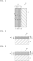
- FIG. 1 is a cross-sectional view showing a configuration of a heat generating element 10 according to a first embodiment used in the heat generating method according to the invention.
- the heat generating element 10 includes a base 11 made of a hydrogen storage metal, a hydrogen storage alloy, or a proton conductor, and a multilayer film 12 provided on a surface of the base 11.
- the hydrogen storage metal include Ni, Pd, V, Nb, Ta, and Ti.
- Examples of the hydrogen storage alloy include LaNi 5 , CaCu 5 , MgZn 2 , ZrNi 2 , ZrCr 2 , TiFe, TiCo, Mg 2 Ni, and Mg 2 Cu.
- Examples of the proton conductor include a BaCeO 3 -based (for example, Ba(Ce 0.95 Y 0.05 )O 3-6 ) conductor, a SrCeO 3 -based (for example, Sr(Ce 0.95 Y 0.05 )O 3-6 ) conductor, a CaZrO 3 -based (for example, CaZr 0.95 Y 0.05 O 3- ⁇ ) conductor, a SrZrO 3 -based (for example, SrZr 0.9 Y 0.1 O 3- ⁇ ) conductor, ⁇ Al 2 O 3 , and ⁇ Ga 2 O 3 .
- a BaCeO 3 -based for example, Ba(Ce 0.95 Y 0.05 )O 3-6
- SrCeO 3 -based for example, Sr(Ce 0.95 Y 0.05 )O 3-6
- CaZrO 3 -based for example, CaZr 0.95 Y 0.05 O 3- ⁇
- the base 11 may be formed of a porous body or a hydrogen permeable film.
- the porous body has pores having a size allowing the hydrogen-based gas to permeate therethrough.
- the porous body is formed of a metal, a non-metal, ceramics, or the like.
- the porous body is preferably formed of a material that does not inhibit a reaction between the hydrogen-based gas and the multilayer film 12.
- the hydrogen permeable film is formed of, for example, a hydrogen storage metal or a hydrogen storage alloy.
- the hydrogen permeable film includes a film having a mesh-shaped sheet.
- the multilayer film 12 has a stacked configuration including a first layer 14 made of a hydrogen storage metal or a hydrogen storage alloy and having a thickness of less than 1, 000 nm, and a second layer 15 made of a hydrogen storage metal or a hydrogen storage alloy, which is different from that of the first layer 14, or ceramics and having a thickness of less than 1,000 nm.
- An interface between the base 11 and the first layer 14 and an interface between the first layer 14 and the second layer 15 are heterogeneous material interfaces 17.
- the multilayer film 12 is provided on a front surface of the base 11 in FIG. 1 , the multilayer film 12 may be provided on a back surface of the base 11 or on both surfaces of the base 11.
- the first layer 14 is formed of, for example, any one of Ni, Pd, Cu, Mn, Cr, Fe, Mg, Co, and an alloy thereof.
- the alloy for forming the first layer 14 is preferably an alloy made of two or more of Ni, Pd, Cu, Mn, Cr, Fe, Mg, and Co.
- the alloy for forming the first layer 14 may be an alloy obtained by adding an additive element to Ni, Pd, Cu, Mn, Cr, Fe, Mg, or Co.
- the second layer 15 is formed of, for example, any one of Ni, Pd, Cu, Mn, Cr, Fe, Mg, Co, an alloy thereof, and SiC.
- the alloy for forming the second layer 15 is preferably an alloy made of two or more of Ni, Pd, Cu, Mn, Cr, Fe, Mg, and Co.
- the alloy for forming the second layer 15 may be an alloy obtained by adding an additive element to Ni, Pd, Cu, Mn, Cr, Fe, Mg, or Co.
- a combination of the first layer 14 and the second layer 15 is preferably Pd-Ni, Ni-Cu, Ni-Cr, Ni-Fe, Ni-Mg, or Ni-Co when types of elements are expressed as "first layer 14-second layer 15".
- first layer 14-second layer 15 is preferably Ni-SiC.
- the thickness of the first layer 14 and the thickness of the second layer 15 are each preferably less than 1,000 nm. When the thickness of each of the first layer 14 and the second layer 15 is 1,000 nm or more, it is difficult for hydrogen to permeate through the multilayer film 12. When the thickness of each of the first layer 14 and the second layer 15 is less than 1,000 nm, a nanostructure that does not exhibit bulk properties can be maintained.
- the thickness of each of the first layer 14 and the second layer 15 is more preferably less than 500 nm. When the thickness of each of the first layer 14 and the second layer 15 is less than 500 nm, a nanostructure that does not exhibit bulk properties completely can be maintained.
- the multilayer film 12 has a configuration in which the first layer 14 and the second layer 15 are alternately stacked in this order on the surface of the base 11, but not limited thereto.
- the multilayer film 12 may have a configuration in which the second layer 15 and the first layer 14 are alternately stacked in this order on the surface of the base 11.
- the number of layers of the first layer 14 and the second layer 15 may be changed as appropriate.
- the multilayer film 12 may include one or more first layers 14 and one or more second layers 15, and may be formed with one or more heterogeneous material interfaces 17.
- FIG. 2 is a cross-sectional view showing a configuration of a heat generating element 20 according to a second embodiment used in the heat generating method according to the invention.
- the heat generating element 20 includes the base 11 and a multilayer film 22 provided on the surface of the base 11.
- the multilayer film 22 has a stacked configuration including the first layer 14, the second layer 15, and a third layer 24 made of a hydrogen storage metal, a hydrogen storage alloy, or ceramics different from those of the first layer 14 and the second layer 15 and having a thickness of less than 1,000 nm.
- the description of the base 11, the first layer 14, and the second layer 15 will be omitted.
- An interface between the first layer 14 and the third layer 24 is a heterogeneous material interface 27.
- the heterogeneous material interface 27 allows hydrogen atoms to permeate therethrough.
- the multilayer film 22 is provided on the front surface of the base 11 in FIG. 2
- the multilayer film 22 may be provided on the back surface of the base 11 or on both surfaces of the base 11.
- the third layer 24 is formed of, for example, any one of Ni, Pd, Cu, Cr, Fe, Mg, Co, an alloy thereof, SiC, CaO, Y 2 O 3 , TiC, LaB 6 , SrO, and BaO.
- the alloy for forming the third layer 24 is preferably an alloy made of two or more of Ni, Pd, Cu, Cr, Fe, Mg, and Co.
- the alloy for forming the third layer 24 may be an alloy obtained by adding an additive element to Ni, Pd, Cu, Cr, Fe, Mg, or Co.
- the third layer 24 is preferably formed of any one of CaO, Y 2 O 3 , TiC, LaB 6 , SrO, and BaO.
- the heat generating element 20 having the third layer 24 formed of any one of CaO, Y 2 O 3 , TiC, LaB 6 , SrO, and BaO an occluding amount of hydrogen is increased, an amount of hydrogen permeating through the heterogeneous material interface 17 and the heterogeneous material interface 27 is increased, and a high output of excess heat can be achieved.
- the thickness of the third layer 24 formed of any one of CaO, Y 2 O 3 , TiC, LaB 6 , SrO, and BaO is preferably 10 nm or less .
- the hydrogen atoms can easily permeate through the multilayer film 22.
- the third layer 24 formed of any one of CaO, Y 2 O 3 , TiC, LaB 6 , SrO, and BaO may be formed in an island shape instead of being formed in a complete film shape.
- the first layer 14 and the third layer 24 are preferably continuously formed in a vacuum state. Accordingly, between the first layer 14 and the third layer 24, no natural oxide film is formed and only the heterogeneous material interface 27 is formed.
- a combination of the first layer 14, the second layer 15, and the third layer 24 is preferably Pd-CaO-Ni, Pd-Y 2 O 3 -Ni, Pd-TiC-Ni, Pd-LaB 6 -Ni, Ni-CaO-Cu, Ni-Y 2 O 3 -Cu, Ni-TiC-Cu, Ni-LaB 6 -Cu, Ni-Co-Cu, Ni-CaO-Cr, Ni-Y 2 O 3 -Cr, Ni-TiC-Cr, Ni-LaB 6 -Cr, Ni-CaO-Fe, Ni-Y 2 O 3 -Fe, Ni-TiC-Fe, Ni-LaB 6 -Fe, Ni-Cr-Fe, Ni-CaO-Mg, Ni-Y 2 O 3 -Mg, Ni-TiC-Mg, Ni-LaB 6 -Mg, Ni-CaO-Co, Ni-Y 2 O 3 -Co, Ni-TiC-Co,
- the multilayer film 22 has a configuration in which the first layer 14, the second layer 15, the first layer 14, and the third layer 24 are sequentially stacked on the surface of the base 11, but not limited thereto.
- the multilayer film 22 may have a configuration in which the second layer 15 and the third layer 24 are disposed in any order on the surface of the base 11, and the first layer 14 is provided between the second layer 15 and the third layer 24.
- the multilayer film 22 may have a configuration in which the first layer 14, the third layer 24, the first layer 14, and the second layer 15 are sequentially stacked on the surface of the base 11.
- the number of layers of the first layer 14, the second layer 15, and the third layer 24 may be changed as appropriate.
- the multilayer film 22 may include one or more third layers 24, and may be formed with one or more heterogeneous material interfaces 27.
- FIG. 3 is a cross-sectional view showing a configuration of a heat generating element 30 according to a third embodiment used in the heat generating method according to the invention.
- the heat generating element 30 includes the base 11 and a multilayer film 32 provided on the surface of the base 11.
- the multilayer film 32 has a stacked configuration including the first layer 14, the second layer 15, the third layer 24, and a fourth layer 34 made of a hydrogen storage metal, a hydrogen storage alloy, or ceramics different from those of the first layer 14, the second layer 15, and the third layer 24 and having a thickness of less than 1, 000 nm.
- the description of the base 11, the first layer 14, the second layer 15, and the third layer 24 will be omitted.
- An interface between the first layer 14 and the fourth layer 34 is a heterogeneous material interface 37.
- the heterogeneous material interface 37 allows hydrogen atoms to permeate therethrough.
- the multilayer film 32 is provided on the front surface of the base 11 in FIG. 3 , the multilayer film 32 may be provided on the back surface of the base 11 or on both surfaces of the base 11.
- the fourth layer 34 is formed of, for example, any one of Ni, Pd, Cu, Cr, Fe, Mg, Co, an alloy thereof, SiC, CaO, Y 2 O 3 , TiC, LaB 6 , SrO, and BaO.
- the alloy for forming the fourth layer 34 is preferably an alloy made of two or more of Ni, Pd, Cu, Cr, Fe, Mg, and Co.
- the alloy for forming the fourth layer 34 may be an alloy obtained by adding an additive element to Ni, Pd, Cu, Cr, Fe, Mg, or Co.
- the fourth layer 34 is preferably formed of any one of CaO, Y 2 O 3 , TiC, LaB 6 , SrO, and BaO.
- the heat generating element 30 having the fourth layer 34 formed of any one of CaO, Y 2 O 3 , TiC, LaB 6 , SrO, and BaO an occluding amount of hydrogen is increased, an amount of hydrogen permeating through the heterogeneous material interface 17, the heterogeneous material interface 27, and the heterogeneous material interface 37 is increased, and a high output of excess heat can be achieved.
- the thickness of the fourth layer 34 formed of any one of CaO, Y 2 O 3 , TiC, LaB 6 , SrO, and BaO is preferably 10 nm or less.
- the hydrogen atoms can easily permeate through the multilayer film 32.
- the fourth layer 34 formed of any one of CaO, Y 2 O 3 , TiC, LaB 6 , SrO, and BaO may be formed in an island shape instead of being formed in a complete film shape.
- the first layer 14 and the fourth layer 34 are preferably continuously formed in a vacuum state. Accordingly, between the first layer 14 and the fourth layer 34, no natural oxide film is formed and only the heterogeneous material interface 37 is formed.
- a combination of the first layer 14, the second layer 15, the third layer 24, and the fourth layer 34 is preferably Ni-CaO-Cr-Fe, Ni-Y 2 O 3 -Cr-Fe, Ni-TiC-Cr-Fe, or Ni-LaB 6 -Cr-Fe when types of elements are expressed as "first layer 14-fourth layer 34-third layer 24-second layer 15".
- the multilayer film 32 has a configuration in which the first layer 14, the second layer 15, the first layer 14, the third layer 24, the first layer 14, and the fourth layer 34 are sequentially stacked on the surface of the base 11, but not limited thereto.
- the multilayer film 32 may have a configuration in which the second layer 15, the third layer 24, and the fourth layer 34 are disposed in any order on the surface of the base 11, and the first layer 14 is provided between each two of the second layer 15, the third layer 24, and the fourth layer 34.
- the multilayer film 32 may have a configuration in which the first layer 14, the fourth layer 34, the first layer 14, the third layer 24, the first layer 14, and the second layer 15 are sequentially stacked on the surface of the base 11.
- the number of layers of the first layer 14, the second layer 15, the third layer 24, and the fourth layer 34 may be changed as appropriate.
- the multilayer film 32 may include one or more fourth layers 34, and may be formed with one or more heterogeneous material interfaces 37.
- a mechanism by which the heat generating element generates excess heat will be described.
- hydrogen is occluded at a high density in the base and the multilayer film of the heat generating element. Even when the supply of the hydrogen-based gas is stopped, the heat generating element can maintain a state where hydrogen is occluded in the base and the multilayer film.
- the heat generating element is heated by the heater, hydrogen occluded in the base and the multilayer film is quantum-diffused while hopping. It is known that hydrogen is light and hops in a manner of quantum diffusion at a site (octahedral site or tetrahedral site) occupied by hydrogen of a certain substance A and substance B.
- the heat generating element generates heat (generates excess heat) in a process in which hydrogen permeates or diffuses through the heterogeneous material interface of the multilayer film in a manner of quantum diffusion.
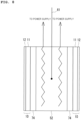
- FIG. 4 shows a state where hydrogen atoms in a metal lattice of the first layer 14 permeate through the heterogeneous material interface 17 and move to a metal lattice of the second layer 15 in the heat generating element 10 having the first layer 14 and the second layer 15 each formed of a hydrogen storage metal having a face-centered cubic structure.
- the heat generating element 10 generates excess heat in a process in which hydrogen permeates or diffuses through the heterogeneous material interface 17 of the multilayer film 12 in a manner of quantum diffusion.
- the heat generating element 20 generates excess heat in a process in which hydrogen permeates or diffuses through the heterogeneous material interface 17 and the heterogeneous material interface 27 of the multilayer film 22 in a manner of quantum diffusion (see FIG. 2 ) .
- the heat generating element 30 generates excess heat in a process in which hydrogen permeates or diffuses through the heterogeneous material interface 17, the heterogeneous material interface 27, and the heterogeneous material interface 37 of the multilayer film 32 in a manner of quantum diffusion (see FIG. 3 ).
- a base formed in a plate shape is prepared.
- a multilayer film is formed on the base using a sputtering method. Accordingly, a plate-shaped heat generating element can be produced.
- the base it is preferable that the base is formed thicker than each of the first layer, the second layer, the third layer, and the fourth layer, and Ni is used as a material of the base, for example.
- the layers are preferably formed continuously in a vacuum state. This is because no natural oxide film is formed between adjacent layers and only the heterogeneous material interface can be formed between adjacent layers.
- the method for producing the heat generating element is not limited to the sputtering method, and a vapor deposition method, a wet method, a thermal spraying method, an electroplating method, or the like can be used.
- the shape of the heat generating element is a plate shape in the present embodiment, but the shape is not limited thereto, and may be a tubular shape or a columnar shape.
- a base formed in a bottomed tubular shape is prepared.
- a multilayer film is formed on an outer surface of the base by using a wet film forming method.
- a heat generating element having a bottomed tubular shape can be produced.
- the wet film forming method include a spin coating method, a spray coating method, and a dipping method.
- the multilayer film may be formed by using an atomic layer deposition (ALD) method, or may be formed on the base while rotating the base by using a sputtering device provided with a rotation mechanism that rotates the base.
- ALD atomic layer deposition
- the multilayer film is not limited to being provided on the outer surface of the base, and the multilayer film may be provided on an inner surface of the base or on both surfaces of the base.
- the heat generating method includes a heat generating step 41 and a trigger step 42.
- a heat generating method using the heat generating element 10 will be described. Descriptions of a heat generating method using the heat generating element 20 and a heat generating method using the heat generating element 30 will be omitted because those heat generating methods are the same as the heat generating method using the heat generating element 10 except that configurations of the heat generating elements are different.
- the heat generating element 10 is heated by a heater to cause a first heat generating reaction in which the heat generating element 10 generates heat with a first heat generation amount.
- the heater includes various heat generating devices such as a ceramic heater and an electric furnace.
- the heater is electrically connected to a power supply, and generates heat when input power is applied from the power supply.
- a temperature of the heater is detected using a temperature sensor.
- the power supply and the temperature sensor are electrically connected to a power control unit.
- the power control unit controls the input power from the power supply based on a detection result of the temperature sensor.
- Methods for causing the heat generating element 10 to generate heat in the heat generating step 41 include a method using a batch method and a method using a transmission method. First, the batch method will be described, and then the transmission method will be described.
- the heat generating device using the batch method includes: the above-mentioned heat generating element 10; a hollow container that accommodates the heat generating element 10; a heater that heats the heat generating element 10; a gas introduction unit that introduces a hydrogen-based gas to an inside of the container; a gas discharge unit that discharges the hydrogen-based gas in the inside of the container to an outside of the container; and a temperature sensor that detects a temperature of the heat generating element 10.
- the container is made of a material having heat resistance and pressure resistance.
- the material of the container is not particularly limited, and examples thereof include carbon steel, austenitic stainless steel, heat-resistant nonferrous alloy steel, and quartz glass.
- the material of the container may be a material that reflects radiant heat generated by the heat generating element, for example, Ni, Cu, or Mo.
- the shape of the container is not particularly limited, and may be a cylindrical shape, an elliptic cylindrical shape, a square tubular shape, or the like.
- the container includes a pressure sensor that detects a pressure inside the container, a gas introduction port connected to the gas introduction unit, a gas discharge port connected to the gas discharge unit, and the like.
- the gas introduction unit introduces the hydrogen-based gas to the inside of the container through the gas introduction port.
- the gas discharge unit vacuum-evacuates the inside of the container through the gas discharge port.
- the gas discharge unit can control the pressure inside the container by adjusting a discharge amount of the hydrogen-based gas based on a detection result of the pressure sensor.
- the heat generating step 41 using the batch method will be described.
- the hydrogen-based gas is supplied to the inside of the container by the gas introduction unit. Accordingly, hydrogen contained in the hydrogen-based gas is occluded in the heat generating element 10.
- the introduction of the hydrogen-based gas to the inside of the container is stopped, the inside of the container is vacuum-evacuated by the gas discharge unit, and the heat generating element 10 is heated by the heater. Accordingly, hydrogen occluded in the heat generating element 10 is discharged from the heat generating element 10.
- the heat generating element 10 generates heat by allowing hydrogen to permeate through the heterogeneous material interface 17 in a manner of quantum diffusion in a process of occluding hydrogen, and generates heat by allowing hydrogen to permeate through the heterogeneous material interface 17 in a manner of quantum diffusion in a process of discharging hydrogen.
- the heat generating element 10 generates excess heat by occluding and discharging hydrogen. The occlusion and discharge of hydrogen may be repeatedly performed.
- the heat generating device using the transmission method includes: the above-mentioned heat generating element 10; a container having a first chamber and a second chamber partitioned by the heat generating element 10; a heater that heats the heat generating element 10; a gas introduction unit that supplies a hydrogen-based gas to the inside of the first chamber; a gas discharge unit that discharges the hydrogen-based gas in the inside of the second chamber to an outside of the second chamber; and a temperature sensor that detects the temperature of the heat generating element 10.
- the container is made of a material having heat resistance and pressure resistance.
- the material of the container examples include carbon steel, austenitic stainless steel, and heat-resistant nonferrous alloy steel.
- the material of the container may be a material that reflects radiant heat generated by the heat generating element, for example, Ni, Cu, or Mo.
- the shape of the container is not particularly limited, and may be a cylindrical shape, an elliptic cylindrical shape, a square tubular shape, or the like.
- the container includes a first pressure sensor that detects a pressure inside the first chamber, a second pressure sensor that detects a pressure inside the second chamber, and the like.
- the first chamber has a gas introduction port connected to the gas introduction unit
- the second chamber has a gas discharge port connected to the gas discharge unit.
- the gas introduction unit introduces the hydrogen-based gas to the inside of the first chamber through the gas introduction port.
- the gas introduction unit can control the pressure inside the first chamber by adjusting an introduction amount of the hydrogen-based gas based on a detection result of the first pressure sensor.
- the gas discharge unit vacuum-evacuates the inside of the second chamber through the gas discharge port.
- the gas discharge unit can control the pressure inside the second chamber by adjusting a discharge amount of the hydrogen-based gas based on a detection result of the second pressure sensor.
- the heat generating step 41 using the transmission method will be described.
- the hydrogen-based gas is introduced to the inside of the first chamber, and the inside of the second chamber is vacuum-evacuated. Accordingly, a hydrogen partial pressure in the first chamber increases, a hydrogen partial pressure in the second chamber decreases, and a difference in hydrogen partial pressure occurs on both sides of the heat generating element 10.
- a hydrogen molecule contained in the hydrogen-based gas is adsorbed on one surface (referred to as a front surface) of the heat generating element 10 disposed on a high-pressure side, and the hydrogen molecule is dissociated into two hydrogen atoms.
- the hydrogen atoms diffuse and pass through the inside of the heat generating element 10.
- the heat generating element 10 allows hydrogen to permeate from the high pressure side to the low pressure side.
- permeate means that hydrogen is occluded on the front surface of the heat generating element and hydrogen is discharged from the back surface of the heat generating element.
- the heat generating element 10 generates heat by occluding hydrogen, and also generates heat by discharging hydrogen.
- excess heat can be efficiently generated since the occlusion of hydrogen on the front surface of the heat generating element 10 and the discharge of hydrogen on the back surface of the heat generating element 10 are simultaneously performed, and hydrogen continuously permeates through the heat generating element 10.
- the hydrogen partial pressure may be referred to as "pressure of hydrogen”.
- a perturbation is imparted to input power to be applied to the heater in a state where the first heat generating reaction is occurring to trigger the second heat generating reaction in which the heat generating element 10 generates heat with a second heat generation amount larger than the first heat generation amount.
- the term "perturbation" to the input power means that, when a value of the input power immediately before the perturbation is imparted is set as a reference value, within a time of a specific range, after a variation of the input power within a specific range is added with respect to the reference value, the input power returns to the reference value.
- the expression "variation of the input power within a specific range” is a variation of the input power in which ⁇ Pin/Pin is within a range of, for example, 0.01% or more and 100% or less when Pin represents the value of the input power immediately before the perturbation is imparted (the reference value) and ⁇ Pin represents a magnitude of the variation of the input power (also referred to as a magnitude of perturbation).
- time of a specific range is, for example, a time within a range of 0.1 minutes or longer and 100 minutes or shorter.
- immediate before the perturbation is imparted means, for example, about several seconds to several minutes before the perturbation is imparted.
- returns to the reference value means that the input power before and after the perturbation is substantially the same, and is not limited to a case where a difference between values of the input power before and after the perturbation is strictly set to 0 (zero).
- FIG. 6 is a diagram illustrating a way of imparting the perturbation.
- ⁇ Pin/Pin is preferably in a range of 0.01% or more and 100% or less, and more preferably in a range of 0.1% or more and 30% or less.
- a time t during which the perturbation is imparted is preferably in a range of 0.1 minutes or longer and 100 minutes or shorter, and more preferably in a range of 1 minute or longer and 10 minutes or shorter.
- the t is appropriately set according to a magnitude of ⁇ Pin or a magnitude of ⁇ Pin/Pin, and may be set to a short time when ⁇ Pin is large, for example.
- the perturbation can be imparted by decreasing and then increasing the input power as shown in FIG.
- the perturbation can also be imparted by increasing and then decreasing the input power. It is desired that the surface temperature of the heat generating element 10 varies by several degrees Celsius to several tens of degrees Celsius due to the perturbation of the input power.
- the trigger step 42 is performed after a lapse of a predetermined time after the excess heat is generated in the heat generating step 41.
- the trigger step 42 is performed after a lapse of 3 hours or longer after the excess heat is generated in the heat generating step 41.
- the perturbation may be repeatedly performed after a lapse of a predetermined time.
- the perturbation is repeatedly performed after a lapse of 3 hours or longer, and preferably after a lapse of 5 hours or longer.
- the trigger step 42 by imparting the perturbation to the input power to be applied to the heater in a state where the first heat generating reaction is occurring to trigger the second heat generating reaction in which the heat generating element 10 generates heat with the second heat generation amount larger than the first heat generation amount.
- the heat generating reaction can be further enhanced by only imparting the perturbation to the input power as described above without applying a large amount of energy during the heat generating reaction.
- Experiments using a heat generating method in which a heat generating element is caused to generate heat by a batch method and results thereof will be described below.
- the following experiments were performed: Experiment 1 in which the input power was decreased and then increased in the trigger step 42 using the heat generating element 10; Experiment 2 performed in the same manner as Experiment 1 except that the input power was increased and then decreased in the trigger step 42; and Experiment 3 performed in the same manner as Experiment 1 except that the heat generating element 20 was used instead of the heat generating element 10.
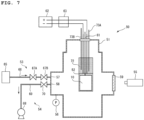
- FIG. 7 is a schematic view showing a configuration of the heat generating device using the batch method.
- FIG. 7 shows a heat generating device 50 in Experiment 1 using the heat generating element 10. Descriptions of the heat generating device in Experiment 2 and the heat generating device in Experiment 3 will be omitted.
- the heat generating device 50 using the batch method includes heat generating elements 10, a container 51, a heater 52, a gas introduction unit 53, a gas discharge unit 54, and temperature sensors 55.
- the heat generating device 50 two heat generating elements 10 were used. In FIG. 7 , only one heat generating element 10 of the two heat generating elements 10 is shown, and the other heat generating element 10 is not shown.
- Each of the heat generating elements 10 has a plate shape, and has a square shape in which one side has a length of 25 mm in a plan view.
- the container 51 is a hollow sealed container that accommodates the heat generating elements 10.
- the container 51 includes a pressure sensor 56 that detects a pressure inside the container 51, a gas introduction port 57 connected to the gas introduction unit 53, a gas discharge port 58 connected to the gas discharge unit 54, and a viewport 59 formed of an infrared transmitting material such as cobalt glass.
- the heater 52 is a plate-shaped ceramic heater, and includes a thermocouple 61 that detects a temperature of the heater 52.
- the thickness of the heater 52 is 2.2 mm.
- the heater 52 is connected to a power supply 62 and a current/voltage meter 63 provided outside the container 51.
- the current/voltage meter 63 detects the input power to be applied to the heater 52.
- the gas introduction unit 53 includes: a gas storage portion 65 that stores a hydrogen-based gas; a gas introduction pipe 66 that connects the gas storage portion 65 and the gas introduction port 57 of the container 51; and adjustment valves 67A and 67B that are provided in the gas introduction pipe 66 and adjust a flow rate and a pressure of the hydrogen-based gas.
- the gas discharge unit 54 includes: a vacuum pump 68 such as a dry pump; a gas discharge pipe 69 that connects the vacuum pump 68 and the gas discharge port 58 of the container 51; and an adjustment valve 70 that adjusts the flow rate and the pressure of the hydrogen-based gas.
- a vacuum pump 68 such as a dry pump
- a gas discharge pipe 69 that connects the vacuum pump 68 and the gas discharge port 58 of the container 51
- an adjustment valve 70 that adjusts the flow rate and the pressure of the hydrogen-based gas.
- the temperature sensors 55 are infrared radiation thermometers provided outside the container 51, and detect surface temperatures of the heat generating elements 10 via the viewport 59 of the container 51.
- FIG. 7 shows the temperature sensor 55 that detects a temperature of one heat generating element 10 of the two heat generating elements 10.
- the temperature sensor 55 that detects a temperature of the other heat generating element 10 of the two heat generating elements 10 is not shown.
- the two heat generating elements 10 and the heater 52 are integrated with each other using a holder 72.
- the holder 72 is formed of, for example, ceramics .
- the holder 72 includes a pair of holder halves (not shown), and holds the heat generating element 10 and the heater 52 between the holder halves. Each of the holder halves has an opening through which the heat generating element 10 is exposed.
- the holder 72 is provided with temperature sensors 73A and 73B that detect a temperature of the holder 72.
- the temperature sensor 73A detects a temperature at a position close to the heat generating element 10, and the temperature sensor 73B detects a temperature at a position away from the heat generating element 10.
- one heat generating element 10 was disposed on both surfaces of the heater 52.
- a shielding plate 74 is provided between the heater 52 and each of the heat generating elements 10.
- As the shielding plate 74 a SiO 2 plate made of SiO 2 and having a thickness of 0.3 mm was used.
- the heat generating element 10 was integrated with the heater 52 by using the holder 72 (see FIG. 7 ) in a state where the base 11 was directed toward the heater 52 and was in contact with the shielding plate 74.
- As the base 11 of the heat generating element 10 an Ni substrate made of Ni and having a thickness of 0.1 mm was used.
- the heat generating element 10 used in Experiment 1 was obtained by forming the multilayer film 12 in which the first layer 14 made of Cu and the second layer 15 made of Ni were stacked on the surface of the base 11 made of Ni.
- the thickness of the first layer 14 was set to 14 nm.
- the thickness of the second layer 15 was set to 2 nm.
- the numbers of layers of the first layer 14 and the second layer 15 were each set to 6.
- the heat generating element 10 used in Experiment 2 is the same as the heat generating element 10 used in Experiment 1.
- the heat generating element 20 used in Experiment 3 was obtained by forming the multilayer film 22 in which the first layer 14 made of Cu, the second layer 15 made of Ni, and the third layer 24 made of CaO were stacked on the surface of the base 11 made of Ni.
- the thickness of the first layer 14 and the thickness of the third layer 24 were each set to 2 nm.
- the thickness of the second layer 15 was set to 7 nm.
- the numbers of layers of the first layer 14 and the third layer 24 were each set to 6.
- the number of layers of the second layer 15 disposed between the first layer 14 and the third layer 24 was 12.
- the heat generating element 10 was baked by the heater 52 to remove water and the like adhering to the surface of the heat generating element 10. Then, as the heat generating step 41, the introduction of the hydrogen-based gas to the inside of the container 51 and the vacuum evacuation of the inside of the container 51 were performed. The hydrogen-based gas was introduced at 80°C to 500°C and at 100 Pa or more. By increasing the temperature of the heater 52 and setting the surface temperature of the heat generating element 10 to 600°C or higher, excess heat was generated from the heat generating element 10. Next, as the trigger step 42, the perturbation was imparted to the input power to be applied to the heater 52 after a lapse of 3 hours or longer since the excess heat was generated in the heat generating step 41.
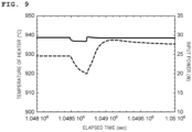
- FIG. 9 is a graph showing a relationship between the input power and the temperature of the heater 52 in Experiment 1.
- a horizontal axis indicates the elapsed time (sec)
- a first vertical axis on a left side indicates the temperature (°C) of the heater 52 detected by the thermocouple 61 of the heater 52
- a second vertical axis on a right side indicates the input power (W) applied to the heater 52.
- the solid line is a graph showing the input power
- the dotted line is a graph showing the temperature of the heater 52.
- the magnitude of the perturbation ⁇ Pin was 0.9 W
- the time t during which the perturbation was imparted was 260 sec.
- An amount of perturbation energy was 230 J.
- the amount of perturbation energy was obtained by integrating the temperature of the heater 52 after perturbation with the time. It was confirmed from FIG. 9 that when comparing the temperatures of the thermocouple 61 before and after the perturbation was imparted, the temperature of the thermocouple 61 increased by 8.3°C by imparting the perturbation.
- FIG. 10 is a graph showing a relationship between the input power and the surface temperature of the heat generating element 10 in Experiment 1.
- a horizontal axis indicates the elapsed time (sec)
- a first vertical axis on a left side indicates the surface temperature (°C) of the heat generating element 10 detected by the temperature sensor 55
- a second vertical axis on a right side indicates the input power (W) applied to the heater 52.
- the solid line is a graph showing the input power
- the dotted line is a graph showing the surface temperature of one heat generating element 10
- the dash-dotted line is a graph showing the surface temperature of the other heat generating element 10. It was confirmed from FIG.
- the surface temperature of one heat generating element 10 indicated by the dotted line increased by 20.3°C and the surface temperature of the other heat generating element 10 indicated by the dash-dotted line increased by 29.6°C by imparting the perturbation.
- An amount of energy of the excess heat was 13,000 J. The amount of energy of the excess heat was obtained by integrating the surface temperature of the heat generating element 10 after perturbation with the time.
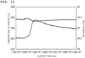
- FIG. 11 is a graph showing a relationship between the input power and the temperature of the heater 52 in Experiment 2.
- a horizontal axis indicates the elapsed time (sec)
- a first vertical axis on a left side indicates the temperature (°C) of the heater 52 detected by the thermocouple 61 of the heater 52
- a second vertical axis on a right side indicates the input power (W) applied to the heater 52.
- the solid line is a graph showing the input power
- the dotted line is a graph showing the temperature of the heater 52.
- the magnitude of the perturbation ⁇ Pin was set to 0.07 W
- the time t during which the perturbation was imparted was set to 264 sec.
- An amount of perturbation energy was 19 J. It was confirmed from FIG. 11 that when comparing the temperatures of the thermocouple 61 before and after the perturbation is imparted, the temperature of the thermocouple 61 increased by 8.0°C by imparting the perturbation.
- FIG. 12 is a graph showing a relationship between the input power and the surface temperature of the heat generating element 10 in Experiment 2.
- a horizontal axis indicates the elapsed time (sec)
- a first vertical axis on a left side indicates the surface temperature (°C) of the heat generating element 10 detected by the temperature sensor 55
- a second vertical axis on a right side indicates the input power (W) applied to the heater 52.
- the solid line is a graph showing the input power
- the dotted line is a graph showing the surface temperature of one heat generating element 10
- the dash-dotted line is a graph showing the surface temperature of the other heat generating element 10. It was confirmed from FIG.
- FIG. 13 is a graph showing a relationship between the input power and the temperature of the heater 52 in Experiment 3.
- a horizontal axis indicates the elapsed time (sec)
- a first vertical axis on a left side indicates the temperature (°C) of the heater 52 detected by the thermocouple 61 of the heater 52
- a second vertical axis on a right side indicates the input power (W) applied to the heater 52.
- the solid line is a graph showing the input power
- the dotted line is a graph showing the temperature of the heater 52.
- the magnitude of the perturbation ⁇ Pin was set to 1.0 W
- the time t during which the perturbation was imparted was set to 210 sec.
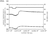
- FIG. 14 is a graph showing a relationship between the input power and the surface temperature of the heat generating element 20 in Experiment 3.
- a horizontal axis indicates the elapsed time (sec)
- a first vertical axis on a left side indicates the surface temperature (°C) of the heat generating element 20 detected by the temperature sensor 55
- a second vertical axis on a right side indicates the input power (W) applied to the heater 52.
- the solid line is a graph showing the input power
- the dotted line is a graph showing the surface temperature of one heat generating element 20
- the dash-dotted line is a graph showing the surface temperature of the other heat generating element 20. It was confirmed from FIG.
- FIG. 15 is a schematic view showing a configuration of the heat generating device using the transmission method.
- a heat generating device 80 using the transmission method includes: the heat generating element 20; a container 83 having a first chamber 81 and a second chamber 82 partitioned by the heat generating element 20; a heater 84 that heats the heat generating element 20; a gas introduction unit 85 that supplies a hydrogen-based gas to an inside of the first chamber 81; a gas discharge unit 86 that discharges the hydrogen-based gas in the inside of the second chamber 82 to an outside of the second chamber 82; and a temperature sensor 87 that detects the temperature of the heat generating element 20.
- the container 83 includes a quartz glass pipe 88, a vacuum pipe 89 for vacuum-evacuating an inside of the quartz glass pipe 88, a mounting pipe 90 for installing the heat generating element 20 in the inside of the quartz glass pipe 88, and the like.
- the quartz glass pipe 88 has a sealed tip end and an open base end.
- the vacuum pipe 89 is connected to the base end of the quartz glass pipe 88.
- the gas discharge unit 86 is connected to the vacuum pipe 89.
- the gas discharge unit 86 includes a turbo molecular pump (TMP) 91, a dry pump (DP) 92, a pressure sensor 93, a gate valve 94, and the like.
- TMP turbo molecular pump
- DP dry pump
- a pressure sensor 93 a pressure sensor 93
- a gate valve 94 a gate valve 94
- the gas discharge unit 86 is not connected to the mounting pipe 90. Therefore, an inside of the mounting pipe 90 is not vacuum-evacuated.
- the mounting pipe 90 is inserted into the inside of the quartz glass pipe 88 through the vacuum pipe 89, and one end of the mounting pipe 90 is disposed outside the vacuum pipe 89 (outside the quartz glass pipe 88) and the other end of the mounting pipe 90 is disposed in the inside of the quartz glass pipe 88.
- the mounting pipe 90 is made of SUS.
- the gas introduction unit 85 that introduces the hydrogen-based gas to the inside of the mounting pipe 90 is connected to one end of the mounting pipe 90.
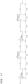
- the gas introduction unit 85 includes a hydrogen cylinder 96 that stores the hydrogen-based gas, a buffer tank 97, flow rate sensors 98A and 98B, pressure sensors 99A and 99B, gate valves 100A, 100B, 100C, 100D, and 100E, an adjustment valve 101, a leak valve 102, and the like.
- a VCR joint 103 is provided at the other end of the mounting pipe 90 such that the heat generating element 20 can be attached to and detached from the VCR joint 103.
- the VCR joint 103 has two leak holes penetrating an inner peripheral surface and an outer peripheral surface of the VCR joint 103 at a position where the heat generating element 20 is disposed.
- the heat generating element 20 is disposed inside the VCR joint 103 in a state of being sandwiched between two SUS gaskets.
- an internal space of the mounting pipe 90 and an internal space of the quartz glass pipe 88 are partitioned by the heat generating element 20.
- the internal space of the mounting pipe 90 is pressurized by the introduction of the hydrogen-based gas.
- the internal space of the quartz glass pipe 88 is depressurized by the vacuum evacuation of the gas. Accordingly, a pressure of hydrogen in the internal space of the mounting pipe 90 is higher than a pressure of hydrogen in the internal space of the quartz glass pipe 88. Therefore, the internal space of the mounting pipe 90 is the first chamber 81, and the internal space of the quartz glass pipe 88 is the second chamber 82.
- the heat generating element 20 When a pressure difference is generated on both sides of the heat generating element 20, hydrogen permeates from the internal space (the first chamber 81) of the mounting pipe 90 on the high-pressure side to the internal space (the second chamber 82) of the quartz glass pipe 88 on the low-pressure side.
- the heat generating element 20 generates heat by occluding hydrogen from one surface disposed on the high-pressure side and generates excess heat by discharging hydrogen from the other surface disposed on the low-pressure side in the process of allowing hydrogen to permeate therethrough.
- thermocouple (a K-type sheath thermocouple) was used as the temperature sensor 87.
- two thermocouples were prepared and inserted into the two leak holes of the VCR joint 103.
- the two thermocouples were in contact with the heat generating element 20, and the temperature of the heat generating element 20 was measured.
- An electric furnace was used as the heater 84.
- the heater 84 as the electric furnace was disposed so as to cover an outer periphery of the quartz glass pipe 88.
- the heat generating element 20 having a diameter of 20 mm in a plan view was used.
- the heat generating element 20 was obtained by forming the multilayer film 22 in which the first layer 14 made of Cu, the second layer 15 made of Ni, and the third layer 24 made of CaO were stacked on both surfaces of the base 11 made of Ni.
- the thickness of the first layer 14 and the thickness of the third layer 24 were each set to 2 nm.
- the thickness of the second layer 15 was set to 7 nm.
- the numbers of layers of the first layer 14 and the third layer 24 were each set to 6.
- the number of layers of the second layer 15 disposed between the first layer 14 and the third layer 24 was 12.
- the heat generating element 20 was baked by the heater 84 to remove water and the like adhering to the surface of the heat generating element 20. Then, as the heat generating step 41, the hydrogen-based gas was supplied to the first chamber 81 (the internal space of the mounting pipe 90), and a pressure in the first chamber 81 was adjusted to 102,000 Pa. The second chamber 82 (the internal space of the quartz glass pipe 88) was vacuum-evacuated, and a pressure in the second chamber 82 was adjusted to 0.003 Pa. By increasing the temperature of the heater 84 and setting the surface temperature of the heat generating element 20 to 600°C or higher, excess heat was generated from the heat generating element 20. Next, as the trigger step 42, perturbation was imparted to the input power to be applied to the heater 84 after a lapse of 3 hours or longer since the excess heat was generated in the heat generating step 41.
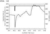
- FIG. 16 is a graph showing a relationship between the input power and the temperature of the heat generating element 20 in Experiment 4.
- a horizontal axis indicates the elapsed time (hour)
- a first vertical axis on a left side indicates the temperature (°C) of the heat generating element 20 detected by the temperature sensor 87
- a second vertical axis on a right side indicates the input power (W) applied to the heater 84.
- the solid line is a graph showing the input power
- the dotted line is a graph showing the temperature of the heat generating element 20.
- the temperature of the heat generating element 20 shown in FIG. 16 is an average value of temperatures measured by two thermocouples as the temperature sensor 87.
- the magnitude of the perturbation ⁇ Pin was set to 99 W, and the time t during which the perturbation was imparted was set to 232 sec. An amount of perturbation energy was 23 kJ. It was confirmed from FIG. 16 that when comparing the temperatures of the heat generating element 20 before and after the perturbation was imparted, the temperature of the heat generating element 20 increased by 16°C by imparting the perturbation. An amount of energy of the excess heat was 160 kJ.
- the heat generating device using the transmission method may further include an inert gas introduction unit that introduces an inert gas to the inside of the second chamber.
- an inert gas for example, argon gas or nitrogen gas is used.
- Experiment 5 was performed in which the perturbation was repeated after a lapse of a predetermined time in the trigger step 42.
- Experiment 5 was performed using the heat generating device 50 using the batch method (see FIG. 7 ).
- the heat generating element 10 having the same configuration as those in Experiment 1 and Experiment 2 was used.
- the multilayer film 12 in which the first layer 14 made of Cu and the second layer 15 made of Ni were stacked was formed on the surface of the base 11 made of Ni, the thickness of the first layer 14 was set to 14 nm, the thickness of the second layer 15 was set to 2 nm, and the numbers of layers of the first layer 14 and the second layer 15 were each set to 6.
- the heat generating element 10 was baked by the heater 52 to remove water and the like adhering to the surface of the heat generating element 10. Then, as the heat generating step 41, the introduction of the hydrogen-based gas to the inside of the container 51 and the vacuum evacuation of the inside of the container 51 were performed.
- the hydrogen-based gas was introduced at 80°C to 500°C and at 100 Pa or more.
- the trigger step 42 the perturbation was imparted to the input power to be applied to the heater 52 after a lapse of 3 hours or longer since the excess heat was generated in the heat generating step 41.
- the trigger step 42 the way of imparting the perturbation in Experiment 1 was combined with the way of imparting the perturbation in Experiment 2.
- a first perturbation also referred to as a negative perturbation
- a second perturbation also referred to as a positive perturbation
- the negative perturbation was performed, then the positive perturbation was performed after the elapse of three hours since the negative perturbation was performed, then the negative perturbation was performed again after the elapse of three hours since the positive perturbation was performed, and the positive perturbation and the negative perturbation were alternately repeated again after the negative perturbation was performed.
- ⁇ P neg represents a magnitude of the negative perturbation with respect to the reference value Pin of the input power.
- ⁇ P pos represents a magnitude of the positive perturbation with respect to the reference value Pin of the input power.
- t neg represents a time during which the negative perturbation is imparted.
- t pos represents a time during which the positive perturbation is imparted.
- t int1 represents a time from when the input power is decreased and then increased by the negative perturbation to when the positive perturbation is performed.
- t int2 represents a time from when the input power is increased and then decreased by the positive perturbation to when the negative perturbation is performed.
- ⁇ P neg , ⁇ P pos , t neg , and t pos satisfy the following Equation 1.
- t neg ⁇ ⁇ P neg t pos ⁇ ⁇ P pos
- ⁇ P neg , ⁇ P pos , t neg , and t pos are set to satisfy the above-mentioned Equation 1, in a specific period including the same number of negative perturbations and positive perturbations, a decrease in input power with respect to the reference value Pin when the negative perturbation is performed and an increase in input power with respect to the reference value Pin when the positive perturbation is performed cancel each other out.
- the time average is the same value as the reference value Pin.
- ⁇ P neg was set to 0.98 W
- ⁇ P pos was set to 1.47 W
- t neg was set to 180 sec
- t pos was set to 120 sec.
- Pin was set to 27.9 W
- both t int1 and t int2 were set to 3 hours.
- FIG. 18 is a graph showing a relationship between the input power and the temperature of the heater 52 in Experiment 5.
- a horizontal axis indicates the elapsed time (hour)
- a first vertical axis on a left side indicates the temperature (°C) of the heater 52 detected by the thermocouple 61 of the heater 52
- a second vertical axis on a right side indicates the input power (W) applied to the heater 52.
- the solid line is a graph showing the input power
- the dotted line is a graph showing the temperature of the heater 52.
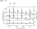
- FIG. 19 is a graph showing a relationship between the input power and the surface temperature of the heat generating element 10 in Experiment 5.
- FIG. 19 is a graph showing a relationship between the input power and the surface temperature of the heat generating element 10 in Experiment 5.
- a horizontal axis indicates the elapsed time (hour)
- a first vertical axis on a left side indicates the surface temperature (°C) of the heat generating element 10 detected by the temperature sensor 55
- a second vertical axis on a right side indicates the input power (W) applied to the heater 52.
- the solid line is a graph showing the input power
- the dash-dotted line is a graph showing the surface temperature of one heat generating element 10
- the chain double-dashed line is a graph showing the surface temperature of the other heat generating element 10.
- a first region R1 in FIGS. 18 and 19 is a region in which the negative perturbation is performed in the vicinity of an elapsed time of 240 hours.
- a second region R2 in FIGS. 18 and 19 is a region in which the positive perturbation is performed in a vicinity of an elapsed time of 243 hours.
- thermocouple 61 gradually increased (see an arrow in FIG. 18 ) and increased by 3.5°C in 20 hours from the elapsed time of 238 hours to the elapsed time of 258 hours. In this period, a peak value of the increase in temperature of the thermocouple 61 was 23°C. It was confirmed from FIG. 19 that the surface temperature of each heat generating element 10 gradually increased (see arrows in FIG.
- the surface temperature of the one heat generating element 10 indicated by the dash-dotted line is higher, but this is considered to be due to variations in production of the heat generating elements 10 (for example, a difference in unevenness of the surface) .
- the amount of energy of the excess heat increased by the perturbation was 38,000 J.
- the input power does not substantially increase, but the amount of energy of the excess heat increased.
- FIG. 20 is a graph showing the first region R1 in FIG. 18 in an enlarged manner. It was confirmed from FIG. 20 that when comparing the temperatures of the thermocouple 61 before and after the negative perturbation was imparted, the temperature of the thermocouple 61 increased by imparting the negative perturbation.
- FIG. 21 is a graph showing the first region R1 in FIG. 19 in an enlarged manner. It was confirmed from FIG. 21 that the surface temperatures of the two heat generating elements 10 before and after imparting the negative perturbation increased.
- FIG. 22 is a graph showing the second region R2 in FIG. 18 in an enlarged manner. It was confirmed from FIG. 22 that when comparing the temperatures of the thermocouple 61 before and after the positive perturbation was imparted, the temperature of the thermocouple 61 increased by imparting the positive perturbation.
- FIG. 23 is a graph showing the second region R2 in FIG. 19 in an enlarged manner. It was confirmed from FIG. 23 that the surface temperatures of the two heat generating elements 10 before and after imparting the positive perturbation increased.
- the heat generated by the heat generating element can be used for various applications.
- the heat generated by the heat generating element can be recovered using, for example, a heat medium.
- the heat medium is heated by the heat generating element to a high temperature.
- the heat medium having a high temperature is used for, for example, household heating, a household water heater, an automobile heater, an agricultural heating machine, a road heater, a seawater desalination heat source, and a geothermal power generation auxiliary heat source.
- the heat medium may be a gas or a liquid, and preferably has excellent heat conductivity and chemical stability. Examples of the gas include a helium gas, an argon gas, a hydrogen gas, a nitrogen gas, water vapor, air, and carbon dioxide.
- the heat medium may be a heat medium having a mixed phase in which solid particles are dispersed in a gas or a liquid.
- the solid particles include a metal, a metal compound, an alloy, and ceramics.
- the metal include copper, nickel, titanium, and cobalt.
- the metal compound include an oxide, a nitride, and a silicide of the above-described metals.
- the alloy include stainless steel and chromium molybdenum steel.
- the ceramics include alumina.
- Examples of applications of the heat generated by the heat generating element include a heat exchanger and a power unit.
- Examples of the heat exchanger include a device that performs heat exchange between a heat medium and a gas, a device that performs heat exchange between a heat medium and a liquid, and a device that performs heat exchange between a heat medium and a solid.
- the device that performs heat exchange between a heat medium and a gas is used for air conditioning, preheating air to be supplied to a combustion device, generation of hot air for drying and hot air for heating, and the like.
- Examples of the combustion device include a boiler, a rotary kiln, a metal heat treatment furnace, a heating furnace for metal processing, a hot air furnace, a firing furnace for ceramics, a petroleum refining tower, a dry distillation furnace, and a drying furnace.
- the device that performs heat exchange between a heat medium and a liquid is used for a heat source of a boiler, oil heating, a chemical reaction tank, and the like.
- the device that performs heat exchange between a heat medium and a solid is used for a double-pipe rotary heater or heating of a particulate matter in a double pipe.
- Examples of the power unit include a gas turbine, a steam turbine, a Stirling engine, and an organic rankine cycle system (ORCS).
Abstract
Provided is a heat generating method for triggering a heat generating reaction of a heat generating element. The heat generating method for triggering a heat generating reaction of a heat generating element includes: a heat generating step 41 of heating, with a heater, a heat generating element and causing a first heat generating reaction in which the heat generating element generates heat with a first heat generation amount, the heat generating element including a base made of a hydrogen storage metal, a hydrogen storage alloy, or a proton conductor, and a multilayer film provided on a surface of the base, and the multilayer film having a stacked configuration including a first layer made of a hydrogen storage metal or a hydrogen storage alloy and having a thickness of less than 1,000 nm, and a second layer made of a hydrogen storage metal or a hydrogen storage alloy, which is different from that of the first layer, or ceramics and having a thickness of less than 1,000 nm; and a trigger step 42 of imparting a perturbation to input power to be applied to the heater in a state where the first heat generating reaction is occurring to trigger a second heat generating reaction in which the heat generating element generates heat with a second heat generation amount larger than the first heat generation amount.
Description
- The present invention relates to a heat generating method.
- In recent years, a heat generation phenomenon in which heat is generated by occluding and discharging hydrogen using a nanostructure formed of a hydrogen storage metal or a hydrogen storage alloy is reported (see, for example, Non-PTL 1) . This heat generation phenomenon can produce a larger amount of thermal energy than a chemical reaction, and is thus expected to be used as an effective heat source or power supply. In addition, from the viewpoint of environmental problems, an arrival of a hydrogen society is expected, and there is a demand for obtaining hydrogen energy having a high energy density with safety by using the above-mentioned heat generation phenomenon.
- Non-PTL 1: A. Kitamura, A. Takahashi, K. Takahashi, R. Seto, T. Hatano, Y. Iwamura, T. Itoh, J. Kasagi, M. Nakamura, M. Uchimura, H. Takahashi, S. Sumitomo, T. Hioki, T. Motohiro, Y. Furuyama, M. Kishida, H. Matsune, "Excess heat evolution from nanocomposite samples under exposure to hydrogen isotope gases", International Journal of Hydrogen Energy 43 (2018) 16187-16200.
- It is known that a heat generating reaction of a nanostructure can be controlled according to a type of a metal constituting the nanostructure and a temperature at which the nanostructure is heated. During the heat generating reaction, in order to further trigger the reaction, it is necessary to apply a large amount of energy to a heat generating element. Therefore, from the viewpoint of necessity of reaction control, there is a strong demand for a method for triggering a heat generating reaction without applying a large amount of energy to a heat generating element during the heat generating reaction.
- Accordingly, an object of the invention is to provide a heat generating method for triggering a heat generating reaction of a heat generating element.
- A heat generating method according to the invention includes: a heat generating step of heating, with a heater, a heat generating element and causing a first heat generating reaction in which the heat generating element generates heat with a first heat generation amount, the heat generating element including a base made of a hydrogen storage metal, a hydrogen storage alloy, or a proton conductor, and a multilayer film provided on a surface of the base, and the multilayer film having a stacked configuration including a first layer made of a hydrogen storage metal or a hydrogen storage alloy and having a thickness of less than 1,000 nm, and a second layer made of a hydrogen storage metal or a hydrogen storage alloy, which is different from that of the first layer, or ceramics and having a thickness of less than 1,000 nm; and a trigger step of imparting a perturbation to input power to be applied to the heater in a state where the first heat generating reaction is occurring to trigger a second heat generating reaction in which the heat generating element generates heat with a second heat generation amount larger than the first heat generation amount.
- According to the invention, the heat generating reaction of the heat generating element can be triggered without applying a large amount of energy to the heat generating element during the heat generating reaction.
-
- [
FIG. 1] FIG. 1 is a cross-sectional view showing a configuration of a heat generating element according to a first embodiment used in a heat generating method according to the invention. - [
FIG. 2] FIG. 2 is a cross-sectional view showing a configuration of a heat generating element according to a second embodiment used in the heat generating method according to the invention. - [
FIG. 3] FIG. 3 is a cross-sectional view showing a configuration of a heat generating element according to a third embodiment used in the heat generating method according to the invention. - [
FIG. 4] FIG. 4 is a diagram illustrating a mechanism by which the heat generating element generates excess heat. - [
FIG. 5] FIG. 5 is a flowchart showing the heat generating method according to the invention. - [
FIG. 6] FIG. 6 is a diagram illustrating a way of imparting a perturbation. - [
FIG. 7] FIG. 7 is a schematic view showing a configuration of a heat generating device using a batch method. - [
FIG. 8] FIG. 8 is a diagram illustrating main parts of the heat generating device using the batch method. - [
FIG. 9] FIG. 9 is a graph showing a relationship between input power and a temperature of a heater in Experiment 1. - [
FIG. 10] FIG. 10 is a graph showing a relationship between the input power and a surface temperature of a heat generating element in Experiment 1. - [
FIG. 11] FIG. 11 is a graph showing a relationship between input power and a temperature of a heater in Experiment 2. - [
FIG. 12] FIG. 12 is a graph showing a relationship between the input power and a surface temperature of a heat generating element in Experiment 2. - [
FIG. 13] FIG. 13 is a graph showing a relationship between input power and a temperature of a heater in Experiment 3. - [
FIG. 14] FIG. 14 is a graph showing a relationship between the input power and a surface temperature of a heat generating element in Experiment 3. - [
FIG. 15] FIG. 15 is a schematic view showing a configuration of a heat generating device using a transmission method. - [
FIG. 16] FIG. 16 is a graph showing a relationship between input power and a temperature of a heat generating element in Experiment 4. - [
FIG. 17] FIG. 17 is a diagram illustrating a way of imparting a perturbation in Experiment 5. - [
FIG. 18] FIG. 18 is a graph showing a relationship between input power and a temperature of a heater in Experiment 5. - [
FIG. 19] FIG. 19 is a graph showing a relationship between the input power and a surface temperature of a heat generating element in Experiment 5. - [
FIG. 20] FIG. 20 is a graph showing a first region R1 inFIG. 18 in an enlarged manner. - [
FIG. 21] FIG. 21 is a graph showing a first region R1 inFIG. 19 in an enlarged manner. - [
FIG. 22] FIG. 22 is a graph showing a second region R2 inFIG. 18 in an enlarged manner. - [
FIG. 23] FIG. 23 is a graph showing a second region R2 inFIG. 19 in an enlarged manner. - Hereinafter, embodiments of the invention will be described with reference to the drawings. In the following description and the drawings, common components are denoted by common reference numerals. The description of the components denoted by the same reference numerals will be omitted as appropriate.
- In a heat generating method according to the invention, a heat generating element that generates heat by occluding and discharging hydrogen contained in a hydrogen-based gas is used. Details of a mechanism by which the heat generating element generates heat will be described later. When the heat generating element is heated by a heater, a temperature of the heat generating element is increased to a temperature equal to or higher than a temperature at which the heat generating element is heated by the heater. The heat generated by the heat generating element whose temperature is increased is referred to as excess heat. The hydrogen-based gas is a gas containing isotopes of hydrogen. As the hydrogen-based gas, at least one of a deuterium gas and a protium gas is used. The protium gas contains a mixture of naturally occurring protium and deuterium, that is, a mixture in which an abundance ratio of protium is 99.985% and an abundance ratio of deuterium is 0.015%. In the following description, when protium and deuterium are not distinguished from each other, both are referred to as "hydrogen".
-
FIG. 1 is a cross-sectional view showing a configuration of aheat generating element 10 according to a first embodiment used in the heat generating method according to the invention. The heat generatingelement 10 includes abase 11 made of a hydrogen storage metal, a hydrogen storage alloy, or a proton conductor, and amultilayer film 12 provided on a surface of thebase 11. Examples of the hydrogen storage metal include Ni, Pd, V, Nb, Ta, and Ti. Examples of the hydrogen storage alloy include LaNi5, CaCu5, MgZn2, ZrNi2, ZrCr2, TiFe, TiCo, Mg2Ni, and Mg2Cu. Examples of the proton conductor include a BaCeO3-based (for example, Ba(Ce0.95Y0.05)O3-6) conductor, a SrCeO3-based (for example, Sr(Ce0.95Y0.05)O3-6) conductor, a CaZrO3-based (for example, CaZr0.95Y0.05O3-α) conductor, a SrZrO3-based (for example, SrZr0.9Y0.1O3-α) conductor, βAl2O3, and βGa2O3. - The
base 11 may be formed of a porous body or a hydrogen permeable film. The porous body has pores having a size allowing the hydrogen-based gas to permeate therethrough. The porous body is formed of a metal, a non-metal, ceramics, or the like. The porous body is preferably formed of a material that does not inhibit a reaction between the hydrogen-based gas and themultilayer film 12. The hydrogen permeable film is formed of, for example, a hydrogen storage metal or a hydrogen storage alloy. The hydrogen permeable film includes a film having a mesh-shaped sheet. - The
multilayer film 12 has a stacked configuration including afirst layer 14 made of a hydrogen storage metal or a hydrogen storage alloy and having a thickness of less than 1, 000 nm, and asecond layer 15 made of a hydrogen storage metal or a hydrogen storage alloy, which is different from that of thefirst layer 14, or ceramics and having a thickness of less than 1,000 nm. An interface between the base 11 and thefirst layer 14 and an interface between thefirst layer 14 and thesecond layer 15 are heterogeneous material interfaces 17. Although themultilayer film 12 is provided on a front surface of the base 11 inFIG. 1 , themultilayer film 12 may be provided on a back surface of the base 11 or on both surfaces of thebase 11. - The
first layer 14 is formed of, for example, any one of Ni, Pd, Cu, Mn, Cr, Fe, Mg, Co, and an alloy thereof. The alloy for forming thefirst layer 14 is preferably an alloy made of two or more of Ni, Pd, Cu, Mn, Cr, Fe, Mg, and Co. The alloy for forming thefirst layer 14 may be an alloy obtained by adding an additive element to Ni, Pd, Cu, Mn, Cr, Fe, Mg, or Co. - The
second layer 15 is formed of, for example, any one of Ni, Pd, Cu, Mn, Cr, Fe, Mg, Co, an alloy thereof, and SiC. The alloy for forming thesecond layer 15 is preferably an alloy made of two or more of Ni, Pd, Cu, Mn, Cr, Fe, Mg, and Co. The alloy for forming thesecond layer 15 may be an alloy obtained by adding an additive element to Ni, Pd, Cu, Mn, Cr, Fe, Mg, or Co. - A combination of the
first layer 14 and thesecond layer 15 is preferably Pd-Ni, Ni-Cu, Ni-Cr, Ni-Fe, Ni-Mg, or Ni-Co when types of elements are expressed as "first layer 14-second layer 15". When thesecond layer 15 is made of ceramics, the "first layer 14-second layer 15" is preferably Ni-SiC. - The thickness of the
first layer 14 and the thickness of thesecond layer 15 are each preferably less than 1,000 nm. When the thickness of each of thefirst layer 14 and thesecond layer 15 is 1,000 nm or more, it is difficult for hydrogen to permeate through themultilayer film 12. When the thickness of each of thefirst layer 14 and thesecond layer 15 is less than 1,000 nm, a nanostructure that does not exhibit bulk properties can be maintained. The thickness of each of thefirst layer 14 and thesecond layer 15 is more preferably less than 500 nm. When the thickness of each of thefirst layer 14 and thesecond layer 15 is less than 500 nm, a nanostructure that does not exhibit bulk properties completely can be maintained. - In
FIG. 1 , themultilayer film 12 has a configuration in which thefirst layer 14 and thesecond layer 15 are alternately stacked in this order on the surface of thebase 11, but not limited thereto. Themultilayer film 12 may have a configuration in which thesecond layer 15 and thefirst layer 14 are alternately stacked in this order on the surface of thebase 11. The number of layers of thefirst layer 14 and thesecond layer 15 may be changed as appropriate. Themultilayer film 12 may include one or morefirst layers 14 and one or moresecond layers 15, and may be formed with one or more heterogeneous material interfaces 17. -
FIG. 2 is a cross-sectional view showing a configuration of aheat generating element 20 according to a second embodiment used in the heat generating method according to the invention. Theheat generating element 20 includes thebase 11 and amultilayer film 22 provided on the surface of thebase 11. Themultilayer film 22 has a stacked configuration including thefirst layer 14, thesecond layer 15, and athird layer 24 made of a hydrogen storage metal, a hydrogen storage alloy, or ceramics different from those of thefirst layer 14 and thesecond layer 15 and having a thickness of less than 1,000 nm. The description of thebase 11, thefirst layer 14, and thesecond layer 15 will be omitted. An interface between thefirst layer 14 and thethird layer 24 is aheterogeneous material interface 27. Similar to theheterogeneous material interface 17, theheterogeneous material interface 27 allows hydrogen atoms to permeate therethrough. Although themultilayer film 22 is provided on the front surface of the base 11 inFIG. 2 , themultilayer film 22 may be provided on the back surface of the base 11 or on both surfaces of thebase 11. - The
third layer 24 is formed of, for example, any one of Ni, Pd, Cu, Cr, Fe, Mg, Co, an alloy thereof, SiC, CaO, Y2O3, TiC, LaB6, SrO, and BaO. The alloy for forming thethird layer 24 is preferably an alloy made of two or more of Ni, Pd, Cu, Cr, Fe, Mg, and Co. The alloy for forming thethird layer 24 may be an alloy obtained by adding an additive element to Ni, Pd, Cu, Cr, Fe, Mg, or Co. - In particular, the
third layer 24 is preferably formed of any one of CaO, Y2O3, TiC, LaB6, SrO, and BaO. In theheat generating element 20 having thethird layer 24 formed of any one of CaO, Y2O3, TiC, LaB6, SrO, and BaO, an occluding amount of hydrogen is increased, an amount of hydrogen permeating through theheterogeneous material interface 17 and theheterogeneous material interface 27 is increased, and a high output of excess heat can be achieved. The thickness of thethird layer 24 formed of any one of CaO, Y2O3, TiC, LaB6, SrO, and BaO is preferably 10 nm or less . Accordingly, the hydrogen atoms can easily permeate through themultilayer film 22. Thethird layer 24 formed of any one of CaO, Y2O3, TiC, LaB6, SrO, and BaO may be formed in an island shape instead of being formed in a complete film shape. Thefirst layer 14 and thethird layer 24 are preferably continuously formed in a vacuum state. Accordingly, between thefirst layer 14 and thethird layer 24, no natural oxide film is formed and only theheterogeneous material interface 27 is formed. - A combination of the
first layer 14, thesecond layer 15, and thethird layer 24 is preferably Pd-CaO-Ni, Pd-Y2O3-Ni, Pd-TiC-Ni, Pd-LaB6-Ni, Ni-CaO-Cu, Ni-Y2O3-Cu, Ni-TiC-Cu, Ni-LaB6-Cu, Ni-Co-Cu, Ni-CaO-Cr, Ni-Y2O3-Cr, Ni-TiC-Cr, Ni-LaB6-Cr, Ni-CaO-Fe, Ni-Y2O3-Fe, Ni-TiC-Fe, Ni-LaB6-Fe, Ni-Cr-Fe, Ni-CaO-Mg, Ni-Y2O3-Mg, Ni-TiC-Mg, Ni-LaB6-Mg, Ni-CaO-Co, Ni-Y2O3-Co, Ni-TiC-Co, Ni-LaB6-Co, Ni-CaO-SiC, Ni-Y2O3-SiC, Ni-TiC-SiC, or Ni-LaB6-SiC when types of elements are expressed as "first layer 14-third layer 24-second layer 15". - In
FIG. 2 , themultilayer film 22 has a configuration in which thefirst layer 14, thesecond layer 15, thefirst layer 14, and thethird layer 24 are sequentially stacked on the surface of thebase 11, but not limited thereto. Themultilayer film 22 may have a configuration in which thesecond layer 15 and thethird layer 24 are disposed in any order on the surface of thebase 11, and thefirst layer 14 is provided between thesecond layer 15 and thethird layer 24. For example, themultilayer film 22 may have a configuration in which thefirst layer 14, thethird layer 24, thefirst layer 14, and thesecond layer 15 are sequentially stacked on the surface of thebase 11. The number of layers of thefirst layer 14, thesecond layer 15, and thethird layer 24 may be changed as appropriate. Themultilayer film 22 may include one or morethird layers 24, and may be formed with one or more heterogeneous material interfaces 27. -
FIG. 3 is a cross-sectional view showing a configuration of aheat generating element 30 according to a third embodiment used in the heat generating method according to the invention. Theheat generating element 30 includes thebase 11 and amultilayer film 32 provided on the surface of thebase 11. Themultilayer film 32 has a stacked configuration including thefirst layer 14, thesecond layer 15, thethird layer 24, and afourth layer 34 made of a hydrogen storage metal, a hydrogen storage alloy, or ceramics different from those of thefirst layer 14, thesecond layer 15, and thethird layer 24 and having a thickness of less than 1, 000 nm. The description of thebase 11, thefirst layer 14, thesecond layer 15, and thethird layer 24 will be omitted. An interface between thefirst layer 14 and thefourth layer 34 is aheterogeneous material interface 37. Similar to theheterogeneous material interface 17 and theheterogeneous material interface 27, theheterogeneous material interface 37 allows hydrogen atoms to permeate therethrough. Although themultilayer film 32 is provided on the front surface of the base 11 inFIG. 3 , themultilayer film 32 may be provided on the back surface of the base 11 or on both surfaces of thebase 11. - The
fourth layer 34 is formed of, for example, any one of Ni, Pd, Cu, Cr, Fe, Mg, Co, an alloy thereof, SiC, CaO, Y2O3, TiC, LaB6, SrO, and BaO. The alloy for forming thefourth layer 34 is preferably an alloy made of two or more of Ni, Pd, Cu, Cr, Fe, Mg, and Co. The alloy for forming thefourth layer 34 may be an alloy obtained by adding an additive element to Ni, Pd, Cu, Cr, Fe, Mg, or Co. - In particular, the
fourth layer 34 is preferably formed of any one of CaO, Y2O3, TiC, LaB6, SrO, and BaO. In theheat generating element 30 having thefourth layer 34 formed of any one of CaO, Y2O3, TiC, LaB6, SrO, and BaO, an occluding amount of hydrogen is increased, an amount of hydrogen permeating through theheterogeneous material interface 17, theheterogeneous material interface 27, and theheterogeneous material interface 37 is increased, and a high output of excess heat can be achieved. The thickness of thefourth layer 34 formed of any one of CaO, Y2O3, TiC, LaB6, SrO, and BaO is preferably 10 nm or less. Accordingly, the hydrogen atoms can easily permeate through themultilayer film 32. Thefourth layer 34 formed of any one of CaO, Y2O3, TiC, LaB6, SrO, and BaO may be formed in an island shape instead of being formed in a complete film shape. Thefirst layer 14 and thefourth layer 34 are preferably continuously formed in a vacuum state. Accordingly, between thefirst layer 14 and thefourth layer 34, no natural oxide film is formed and only theheterogeneous material interface 37 is formed. - A combination of the
first layer 14, thesecond layer 15, thethird layer 24, and thefourth layer 34 is preferably Ni-CaO-Cr-Fe, Ni-Y2O3-Cr-Fe, Ni-TiC-Cr-Fe, or Ni-LaB6-Cr-Fe when types of elements are expressed as "first layer 14-fourth layer 34-third layer 24-second layer 15". - In
FIG. 3 , themultilayer film 32 has a configuration in which thefirst layer 14, thesecond layer 15, thefirst layer 14, thethird layer 24, thefirst layer 14, and thefourth layer 34 are sequentially stacked on the surface of thebase 11, but not limited thereto. Themultilayer film 32 may have a configuration in which thesecond layer 15, thethird layer 24, and thefourth layer 34 are disposed in any order on the surface of thebase 11, and thefirst layer 14 is provided between each two of thesecond layer 15, thethird layer 24, and thefourth layer 34. For example, themultilayer film 32 may have a configuration in which thefirst layer 14, thefourth layer 34, thefirst layer 14, thethird layer 24, thefirst layer 14, and thesecond layer 15 are sequentially stacked on the surface of thebase 11. The number of layers of thefirst layer 14, thesecond layer 15, thethird layer 24, and thefourth layer 34 may be changed as appropriate. Themultilayer film 32 may include one or morefourth layers 34, and may be formed with one or more heterogeneous material interfaces 37. - A mechanism by which the heat generating element generates excess heat will be described. By supplying the hydrogen-based gas to the heat generating element, hydrogen is occluded at a high density in the base and the multilayer film of the heat generating element. Even when the supply of the hydrogen-based gas is stopped, the heat generating element can maintain a state where hydrogen is occluded in the base and the multilayer film. When the heat generating element is heated by the heater, hydrogen occluded in the base and the multilayer film is quantum-diffused while hopping. It is known that hydrogen is light and hops in a manner of quantum diffusion at a site (octahedral site or tetrahedral site) occupied by hydrogen of a certain substance A and substance B. The heat generating element generates heat (generates excess heat) in a process in which hydrogen permeates or diffuses through the heterogeneous material interface of the multilayer film in a manner of quantum diffusion.
-
FIG. 4 shows a state where hydrogen atoms in a metal lattice of thefirst layer 14 permeate through theheterogeneous material interface 17 and move to a metal lattice of thesecond layer 15 in theheat generating element 10 having thefirst layer 14 and thesecond layer 15 each formed of a hydrogen storage metal having a face-centered cubic structure. Theheat generating element 10 generates excess heat in a process in which hydrogen permeates or diffuses through theheterogeneous material interface 17 of themultilayer film 12 in a manner of quantum diffusion. Although not shown, theheat generating element 20 generates excess heat in a process in which hydrogen permeates or diffuses through theheterogeneous material interface 17 and theheterogeneous material interface 27 of themultilayer film 22 in a manner of quantum diffusion (seeFIG. 2 ) . Theheat generating element 30 generates excess heat in a process in which hydrogen permeates or diffuses through theheterogeneous material interface 17, theheterogeneous material interface 27, and theheterogeneous material interface 37 of themultilayer film 32 in a manner of quantum diffusion (seeFIG. 3 ). - An example of a method for producing the heat generating element will be described. First, a base formed in a plate shape is prepared. Next, a multilayer film is formed on the base using a sputtering method. Accordingly, a plate-shaped heat generating element can be produced. When forming the base, it is preferable that the base is formed thicker than each of the first layer, the second layer, the third layer, and the fourth layer, and Ni is used as a material of the base, for example. The layers are preferably formed continuously in a vacuum state. This is because no natural oxide film is formed between adjacent layers and only the heterogeneous material interface can be formed between adjacent layers. The method for producing the heat generating element is not limited to the sputtering method, and a vapor deposition method, a wet method, a thermal spraying method, an electroplating method, or the like can be used. The shape of the heat generating element is a plate shape in the present embodiment, but the shape is not limited thereto, and may be a tubular shape or a columnar shape.
- Another example of the method for producing a heat generating element will be described. First, a base formed in a bottomed tubular shape is prepared. Next, a multilayer film is formed on an outer surface of the base by using a wet film forming method. Accordingly, a heat generating element having a bottomed tubular shape can be produced. Examples of the wet film forming method include a spin coating method, a spray coating method, and a dipping method. The multilayer film may be formed by using an atomic layer deposition (ALD) method, or may be formed on the base while rotating the base by using a sputtering device provided with a rotation mechanism that rotates the base. The multilayer film is not limited to being provided on the outer surface of the base, and the multilayer film may be provided on an inner surface of the base or on both surfaces of the base.
- As shown in
FIG. 5 , the heat generating method includes aheat generating step 41 and atrigger step 42. Hereinafter, a heat generating method using theheat generating element 10 will be described. Descriptions of a heat generating method using theheat generating element 20 and a heat generating method using theheat generating element 30 will be omitted because those heat generating methods are the same as the heat generating method using theheat generating element 10 except that configurations of the heat generating elements are different. - In the
heat generating step 41, theheat generating element 10 is heated by a heater to cause a first heat generating reaction in which theheat generating element 10 generates heat with a first heat generation amount. Examples of the heater includes various heat generating devices such as a ceramic heater and an electric furnace. The heater is electrically connected to a power supply, and generates heat when input power is applied from the power supply. A temperature of the heater is detected using a temperature sensor. The power supply and the temperature sensor are electrically connected to a power control unit. The power control unit controls the input power from the power supply based on a detection result of the temperature sensor. - Methods for causing the
heat generating element 10 to generate heat in theheat generating step 41 include a method using a batch method and a method using a transmission method. First, the batch method will be described, and then the transmission method will be described. - An outline of a heat generating device for causing the
heat generating element 10 to generate heat by the batch method will be described. The heat generating device using the batch method includes: the above-mentionedheat generating element 10; a hollow container that accommodates theheat generating element 10; a heater that heats theheat generating element 10; a gas introduction unit that introduces a hydrogen-based gas to an inside of the container; a gas discharge unit that discharges the hydrogen-based gas in the inside of the container to an outside of the container; and a temperature sensor that detects a temperature of theheat generating element 10. The container is made of a material having heat resistance and pressure resistance. The material of the container is not particularly limited, and examples thereof include carbon steel, austenitic stainless steel, heat-resistant nonferrous alloy steel, and quartz glass. The material of the container may be a material that reflects radiant heat generated by the heat generating element, for example, Ni, Cu, or Mo. The shape of the container is not particularly limited, and may be a cylindrical shape, an elliptic cylindrical shape, a square tubular shape, or the like. The container includes a pressure sensor that detects a pressure inside the container, a gas introduction port connected to the gas introduction unit, a gas discharge port connected to the gas discharge unit, and the like. The gas introduction unit introduces the hydrogen-based gas to the inside of the container through the gas introduction port. The gas discharge unit vacuum-evacuates the inside of the container through the gas discharge port. The gas discharge unit can control the pressure inside the container by adjusting a discharge amount of the hydrogen-based gas based on a detection result of the pressure sensor. - The
heat generating step 41 using the batch method will be described. In theheat generating step 41 using the batch method, first, the hydrogen-based gas is supplied to the inside of the container by the gas introduction unit. Accordingly, hydrogen contained in the hydrogen-based gas is occluded in theheat generating element 10. Next, the introduction of the hydrogen-based gas to the inside of the container is stopped, the inside of the container is vacuum-evacuated by the gas discharge unit, and theheat generating element 10 is heated by the heater. Accordingly, hydrogen occluded in theheat generating element 10 is discharged from theheat generating element 10. Theheat generating element 10 generates heat by allowing hydrogen to permeate through theheterogeneous material interface 17 in a manner of quantum diffusion in a process of occluding hydrogen, and generates heat by allowing hydrogen to permeate through theheterogeneous material interface 17 in a manner of quantum diffusion in a process of discharging hydrogen. As described above, in theheat generating step 41 using the batch method, theheat generating element 10 generates excess heat by occluding and discharging hydrogen. The occlusion and discharge of hydrogen may be repeatedly performed. - An outline of a heat generating device for causing the
heat generating element 10 to generate heat by the transmission method will be described. The heat generating device using the transmission method includes: the above-mentionedheat generating element 10; a container having a first chamber and a second chamber partitioned by theheat generating element 10; a heater that heats theheat generating element 10; a gas introduction unit that supplies a hydrogen-based gas to the inside of the first chamber; a gas discharge unit that discharges the hydrogen-based gas in the inside of the second chamber to an outside of the second chamber; and a temperature sensor that detects the temperature of theheat generating element 10. The container is made of a material having heat resistance and pressure resistance. Examples of the material of the container include carbon steel, austenitic stainless steel, and heat-resistant nonferrous alloy steel. The material of the container may be a material that reflects radiant heat generated by the heat generating element, for example, Ni, Cu, or Mo. The shape of the container is not particularly limited, and may be a cylindrical shape, an elliptic cylindrical shape, a square tubular shape, or the like. The container includes a first pressure sensor that detects a pressure inside the first chamber, a second pressure sensor that detects a pressure inside the second chamber, and the like. The first chamber has a gas introduction port connected to the gas introduction unit, and the second chamber has a gas discharge port connected to the gas discharge unit. The gas introduction unit introduces the hydrogen-based gas to the inside of the first chamber through the gas introduction port. The gas introduction unit can control the pressure inside the first chamber by adjusting an introduction amount of the hydrogen-based gas based on a detection result of the first pressure sensor. The gas discharge unit vacuum-evacuates the inside of the second chamber through the gas discharge port. The gas discharge unit can control the pressure inside the second chamber by adjusting a discharge amount of the hydrogen-based gas based on a detection result of the second pressure sensor. - The
heat generating step 41 using the transmission method will be described. In theheat generating step 41 using the transmission method, the hydrogen-based gas is introduced to the inside of the first chamber, and the inside of the second chamber is vacuum-evacuated. Accordingly, a hydrogen partial pressure in the first chamber increases, a hydrogen partial pressure in the second chamber decreases, and a difference in hydrogen partial pressure occurs on both sides of theheat generating element 10. When the difference in hydrogen partial pressure occurs on both sides of theheat generating element 10, a hydrogen molecule contained in the hydrogen-based gas is adsorbed on one surface (referred to as a front surface) of theheat generating element 10 disposed on a high-pressure side, and the hydrogen molecule is dissociated into two hydrogen atoms. The hydrogen atoms after dissociation penetrate into theheat generating element 10. That is, hydrogen is occluded in theheat generating element 10. The hydrogen atoms diffuse and pass through the inside of theheat generating element 10. On the other surface (referred to as a back surface) of theheat generating element 10 disposed on a low-pressure side, the hydrogen atoms that passed through theheat generating element 10 are recombined and discharged as a hydrogen molecule. That is, hydrogen is discharged from theheat generating element 10. In this way, theheat generating element 10 allows hydrogen to permeate from the high pressure side to the low pressure side. The expression "permeate" as used herein means that hydrogen is occluded on the front surface of the heat generating element and hydrogen is discharged from the back surface of the heat generating element. Theheat generating element 10 generates heat by occluding hydrogen, and also generates heat by discharging hydrogen. By generating a difference in hydrogen partial pressure on both sides of theheat generating element 10, excess heat can be efficiently generated since the occlusion of hydrogen on the front surface of theheat generating element 10 and the discharge of hydrogen on the back surface of theheat generating element 10 are simultaneously performed, and hydrogen continuously permeates through theheat generating element 10. In the following description, the hydrogen partial pressure may be referred to as "pressure of hydrogen". - In the
trigger step 42, a perturbation is imparted to input power to be applied to the heater in a state where the first heat generating reaction is occurring to trigger the second heat generating reaction in which theheat generating element 10 generates heat with a second heat generation amount larger than the first heat generation amount. By imparting the perturbation to the input power, a surface temperature of theheat generating element 10 can be perturbed. It is considered that, by imparting the perturbation to theheat generating element 10 in a state where the first heat generating reaction in which heat is generated with the first heat generation amount is occurring, diffusion of hydrogen occluded in theheat generating element 10 is changed, a concentration of hydrogen on the front surface of theheat generating element 10 or on theheterogeneous material interface 17 is changed, and the second heat generating reaction in which heat is generated with the second heat generation amount larger than the first heat generation amount is triggered. In this way, in thetrigger step 42, the heat generation amount can be increased by imparting the perturbation to the surface temperature of theheat generating element 10. In the invention, the term "perturbation" to the input power means that, when a value of the input power immediately before the perturbation is imparted is set as a reference value, within a time of a specific range, after a variation of the input power within a specific range is added with respect to the reference value, the input power returns to the reference value. The expression "variation of the input power within a specific range" is a variation of the input power in which δPin/Pin is within a range of, for example, 0.01% or more and 100% or less when Pin represents the value of the input power immediately before the perturbation is imparted (the reference value) and δPin represents a magnitude of the variation of the input power (also referred to as a magnitude of perturbation). The expression "time of a specific range" is, for example, a time within a range of 0.1 minutes or longer and 100 minutes or shorter. The expression "immediately before the perturbation is imparted" means, for example, about several seconds to several minutes before the perturbation is imparted. The expression "returns to the reference value" means that the input power before and after the perturbation is substantially the same, and is not limited to a case where a difference between values of the input power before and after the perturbation is strictly set to 0 (zero). -
FIG. 6 is a diagram illustrating a way of imparting the perturbation. δPin/Pin is preferably in a range of 0.01% or more and 100% or less, and more preferably in a range of 0.1% or more and 30% or less. A time t during which the perturbation is imparted is preferably in a range of 0.1 minutes or longer and 100 minutes or shorter, and more preferably in a range of 1 minute or longer and 10 minutes or shorter. The t is appropriately set according to a magnitude of δPin or a magnitude of δPin/Pin, and may be set to a short time when δPin is large, for example. The perturbation can be imparted by decreasing and then increasing the input power as shown inFIG. 6 , but is not limited thereto. Although not shown, the perturbation can also be imparted by increasing and then decreasing the input power. It is desired that the surface temperature of theheat generating element 10 varies by several degrees Celsius to several tens of degrees Celsius due to the perturbation of the input power. - It is preferable that the
trigger step 42 is performed after a lapse of a predetermined time after the excess heat is generated in theheat generating step 41. For example, thetrigger step 42 is performed after a lapse of 3 hours or longer after the excess heat is generated in theheat generating step 41. - In the
trigger step 42, the perturbation may be repeatedly performed after a lapse of a predetermined time. For example, the perturbation is repeatedly performed after a lapse of 3 hours or longer, and preferably after a lapse of 5 hours or longer. - In the above-mentioned heat generating method, in the
trigger step 42, by imparting the perturbation to the input power to be applied to the heater in a state where the first heat generating reaction is occurring to trigger the second heat generating reaction in which theheat generating element 10 generates heat with the second heat generation amount larger than the first heat generation amount. As a result, the heat generating reaction can be further enhanced by only imparting the perturbation to the input power as described above without applying a large amount of energy during the heat generating reaction. - Experiments using a heat generating method in which a heat generating element is caused to generate heat by a batch method and results thereof will be described below. As an experiment using the batch method, the following experiments were performed: Experiment 1 in which the input power was decreased and then increased in the
trigger step 42 using theheat generating element 10; Experiment 2 performed in the same manner as Experiment 1 except that the input power was increased and then decreased in thetrigger step 42; and Experiment 3 performed in the same manner as Experiment 1 except that theheat generating element 20 was used instead of theheat generating element 10. - The heat generating device using the batch method used in the experiments will be described.
FIG. 7 is a schematic view showing a configuration of the heat generating device using the batch method.FIG. 7 shows aheat generating device 50 in Experiment 1 using theheat generating element 10. Descriptions of the heat generating device in Experiment 2 and the heat generating device in Experiment 3 will be omitted. - The
heat generating device 50 using the batch method includesheat generating elements 10, acontainer 51, aheater 52, agas introduction unit 53, agas discharge unit 54, andtemperature sensors 55. In theheat generating device 50, twoheat generating elements 10 were used. InFIG. 7 , only oneheat generating element 10 of the twoheat generating elements 10 is shown, and the otherheat generating element 10 is not shown. Each of theheat generating elements 10 has a plate shape, and has a square shape in which one side has a length of 25 mm in a plan view. - The
container 51 is a hollow sealed container that accommodates theheat generating elements 10. Thecontainer 51 includes apressure sensor 56 that detects a pressure inside thecontainer 51, agas introduction port 57 connected to thegas introduction unit 53, agas discharge port 58 connected to thegas discharge unit 54, and aviewport 59 formed of an infrared transmitting material such as cobalt glass. - The
heater 52 is a plate-shaped ceramic heater, and includes athermocouple 61 that detects a temperature of theheater 52. The thickness of theheater 52 is 2.2 mm. Theheater 52 is connected to apower supply 62 and a current/voltage meter 63 provided outside thecontainer 51. The current/voltage meter 63 detects the input power to be applied to theheater 52. - The
gas introduction unit 53 includes: agas storage portion 65 that stores a hydrogen-based gas; agas introduction pipe 66 that connects thegas storage portion 65 and thegas introduction port 57 of thecontainer 51; andadjustment valves gas introduction pipe 66 and adjust a flow rate and a pressure of the hydrogen-based gas. - The
gas discharge unit 54 includes: avacuum pump 68 such as a dry pump; agas discharge pipe 69 that connects thevacuum pump 68 and thegas discharge port 58 of thecontainer 51; and anadjustment valve 70 that adjusts the flow rate and the pressure of the hydrogen-based gas. - The
temperature sensors 55 are infrared radiation thermometers provided outside thecontainer 51, and detect surface temperatures of theheat generating elements 10 via theviewport 59 of thecontainer 51.FIG. 7 shows thetemperature sensor 55 that detects a temperature of oneheat generating element 10 of the twoheat generating elements 10. Thetemperature sensor 55 that detects a temperature of the otherheat generating element 10 of the twoheat generating elements 10 is not shown. - The two
heat generating elements 10 and theheater 52 are integrated with each other using aholder 72. Theholder 72 is formed of, for example, ceramics . Theholder 72 includes a pair of holder halves (not shown), and holds theheat generating element 10 and theheater 52 between the holder halves. Each of the holder halves has an opening through which theheat generating element 10 is exposed. Theholder 72 is provided withtemperature sensors holder 72. Thetemperature sensor 73A detects a temperature at a position close to theheat generating element 10, and thetemperature sensor 73B detects a temperature at a position away from theheat generating element 10. - As shown in
FIG. 8 , oneheat generating element 10 was disposed on both surfaces of theheater 52. A shieldingplate 74 is provided between theheater 52 and each of theheat generating elements 10. As the shieldingplate 74, a SiO2 plate made of SiO2 and having a thickness of 0.3 mm was used. Theheat generating element 10 was integrated with theheater 52 by using the holder 72 (seeFIG. 7 ) in a state where thebase 11 was directed toward theheater 52 and was in contact with the shieldingplate 74. As thebase 11 of theheat generating element 10, an Ni substrate made of Ni and having a thickness of 0.1 mm was used. - The
heat generating element 10 used in Experiment 1 was obtained by forming themultilayer film 12 in which thefirst layer 14 made of Cu and thesecond layer 15 made of Ni were stacked on the surface of the base 11 made of Ni. The thickness of thefirst layer 14 was set to 14 nm. The thickness of thesecond layer 15 was set to 2 nm. The numbers of layers of thefirst layer 14 and thesecond layer 15 were each set to 6. Theheat generating element 10 used in Experiment 2 is the same as theheat generating element 10 used in Experiment 1. Theheat generating element 20 used in Experiment 3 was obtained by forming themultilayer film 22 in which thefirst layer 14 made of Cu, thesecond layer 15 made of Ni, and thethird layer 24 made of CaO were stacked on the surface of the base 11 made of Ni. The thickness of thefirst layer 14 and the thickness of thethird layer 24 were each set to 2 nm. The thickness of thesecond layer 15 was set to 7 nm. The numbers of layers of thefirst layer 14 and thethird layer 24 were each set to 6. The number of layers of thesecond layer 15 disposed between thefirst layer 14 and thethird layer 24 was 12. - An experimental method using the batch method will be described using Experiment 1 as an example. First, the
heat generating element 10 was baked by theheater 52 to remove water and the like adhering to the surface of theheat generating element 10. Then, as theheat generating step 41, the introduction of the hydrogen-based gas to the inside of thecontainer 51 and the vacuum evacuation of the inside of thecontainer 51 were performed. The hydrogen-based gas was introduced at 80°C to 500°C and at 100 Pa or more. By increasing the temperature of theheater 52 and setting the surface temperature of theheat generating element 10 to 600°C or higher, excess heat was generated from theheat generating element 10. Next, as thetrigger step 42, the perturbation was imparted to the input power to be applied to theheater 52 after a lapse of 3 hours or longer since the excess heat was generated in theheat generating step 41. - Results of the experiment using the batch method will be described.
FIG. 9 is a graph showing a relationship between the input power and the temperature of theheater 52 in Experiment 1. InFIG. 9 , a horizontal axis indicates the elapsed time (sec), a first vertical axis on a left side indicates the temperature (°C) of theheater 52 detected by thethermocouple 61 of theheater 52, and a second vertical axis on a right side indicates the input power (W) applied to theheater 52. The solid line is a graph showing the input power, and the dotted line is a graph showing the temperature of theheater 52. In Experiment 1, the magnitude of the perturbation δPin was 0.9 W, and the time t during which the perturbation was imparted was 260 sec. An amount of perturbation energy was 230 J. The amount of perturbation energy was obtained by integrating the temperature of theheater 52 after perturbation with the time. It was confirmed fromFIG. 9 that when comparing the temperatures of thethermocouple 61 before and after the perturbation was imparted, the temperature of thethermocouple 61 increased by 8.3°C by imparting the perturbation. -
FIG. 10 is a graph showing a relationship between the input power and the surface temperature of theheat generating element 10 in Experiment 1. InFIG. 10 , a horizontal axis indicates the elapsed time (sec), a first vertical axis on a left side indicates the surface temperature (°C) of theheat generating element 10 detected by thetemperature sensor 55, and a second vertical axis on a right side indicates the input power (W) applied to theheater 52. The solid line is a graph showing the input power, the dotted line is a graph showing the surface temperature of oneheat generating element 10, and the dash-dotted line is a graph showing the surface temperature of the otherheat generating element 10. It was confirmed fromFIG. 10 that when comparing the surface temperatures of the twoheat generating elements 10 before and after the perturbation was imparted, the surface temperature of oneheat generating element 10 indicated by the dotted line increased by 20.3°C and the surface temperature of the otherheat generating element 10 indicated by the dash-dotted line increased by 29.6°C by imparting the perturbation. An amount of energy of the excess heat was 13,000 J. The amount of energy of the excess heat was obtained by integrating the surface temperature of theheat generating element 10 after perturbation with the time. -
FIG. 11 is a graph showing a relationship between the input power and the temperature of theheater 52 in Experiment 2. InFIG. 11 , a horizontal axis indicates the elapsed time (sec), a first vertical axis on a left side indicates the temperature (°C) of theheater 52 detected by thethermocouple 61 of theheater 52, and a second vertical axis on a right side indicates the input power (W) applied to theheater 52. The solid line is a graph showing the input power, and the dotted line is a graph showing the temperature of theheater 52. In Experiment 2, the magnitude of the perturbation δPin was set to 0.07 W, and the time t during which the perturbation was imparted was set to 264 sec. An amount of perturbation energy was 19 J. It was confirmed fromFIG. 11 that when comparing the temperatures of thethermocouple 61 before and after the perturbation is imparted, the temperature of thethermocouple 61 increased by 8.0°C by imparting the perturbation. -
FIG. 12 is a graph showing a relationship between the input power and the surface temperature of theheat generating element 10 in Experiment 2. InFIG. 12 , a horizontal axis indicates the elapsed time (sec), a first vertical axis on a left side indicates the surface temperature (°C) of theheat generating element 10 detected by thetemperature sensor 55, and a second vertical axis on a right side indicates the input power (W) applied to theheater 52. The solid line is a graph showing the input power, the dotted line is a graph showing the surface temperature of oneheat generating element 10, and the dash-dotted line is a graph showing the surface temperature of the otherheat generating element 10. It was confirmed fromFIG. 12 that when comparing the surface temperatures of the twoheat generating elements 10 before and after the perturbation was imparted, the surface temperature of oneheat generating element 10 indicated by the dotted line increased by 18.0°C and the surface temperature of the otherheat generating element 10 indicated by the dash-dotted line increased by 24.6°C by imparting the perturbation. An amount of energy of the excess heat was 2,600 J. -
FIG. 13 is a graph showing a relationship between the input power and the temperature of theheater 52 in Experiment 3. InFIG. 13 , a horizontal axis indicates the elapsed time (sec), a first vertical axis on a left side indicates the temperature (°C) of theheater 52 detected by thethermocouple 61 of theheater 52, and a second vertical axis on a right side indicates the input power (W) applied to theheater 52. The solid line is a graph showing the input power, and the dotted line is a graph showing the temperature of theheater 52. In Experiment 3, the magnitude of the perturbation δPin was set to 1.0 W, and the time t during which the perturbation was imparted was set to 210 sec. An amount of perturbation energy was 210 J. It was confirmed fromFIG. 13 that when comparing the temperatures of thethermocouple 61 before and after the perturbation was imparted, the temperature of thethermocouple 61 increased by 3.8°C by imparting the perturbation. -
FIG. 14 is a graph showing a relationship between the input power and the surface temperature of theheat generating element 20 in Experiment 3. InFIG. 14 , a horizontal axis indicates the elapsed time (sec), a first vertical axis on a left side indicates the surface temperature (°C) of theheat generating element 20 detected by thetemperature sensor 55, and a second vertical axis on a right side indicates the input power (W) applied to theheater 52. The solid line is a graph showing the input power, the dotted line is a graph showing the surface temperature of oneheat generating element 20, and the dash-dotted line is a graph showing the surface temperature of the otherheat generating element 20. It was confirmed fromFIG. 14 that when comparing the surface temperatures of the twoheat generating elements 20 before and after the perturbation was imparted, the surface temperature of oneheat generating element 20 indicated by the dotted line increased by 13.7°C and the surface temperature of the otherheat generating element 20 indicated by the dash-dotted line increased by 6.2°C by imparting the perturbation. An amount of energy of the excess heat was 1,560 J. - According to Experiments 1 to 3 described above, in the batch method, by imparting the perturbation to the input power to be applied to the
heater 52, it is possible to trigger the heat generating reaction of the heat generating element and increase the heat generation amount without applying a large amount of energy to the heat generating element. - An experiment using a heat generating method in which a heat generating element is caused to generate heat by a transmission method and results thereof will be described below. As the experiment using the transmission method, Experiment 4 was performed in which input power was decreased and then increased in the
trigger step 42 by using theheat generating element 20. - The heat generating device using the transmission method used in the experiments will be described.
FIG. 15 is a schematic view showing a configuration of the heat generating device using the transmission method. - A
heat generating device 80 using the transmission method includes: theheat generating element 20; acontainer 83 having afirst chamber 81 and asecond chamber 82 partitioned by theheat generating element 20; aheater 84 that heats theheat generating element 20; agas introduction unit 85 that supplies a hydrogen-based gas to an inside of thefirst chamber 81; agas discharge unit 86 that discharges the hydrogen-based gas in the inside of thesecond chamber 82 to an outside of thesecond chamber 82; and atemperature sensor 87 that detects the temperature of theheat generating element 20. - The
container 83 includes aquartz glass pipe 88, avacuum pipe 89 for vacuum-evacuating an inside of thequartz glass pipe 88, a mountingpipe 90 for installing theheat generating element 20 in the inside of thequartz glass pipe 88, and the like. Thequartz glass pipe 88 has a sealed tip end and an open base end. - The
vacuum pipe 89 is connected to the base end of thequartz glass pipe 88. Thegas discharge unit 86 is connected to thevacuum pipe 89. Thegas discharge unit 86 includes a turbo molecular pump (TMP) 91, a dry pump (DP) 92, apressure sensor 93, agate valve 94, and the like. Thegas discharge unit 86 is not connected to the mountingpipe 90. Therefore, an inside of the mountingpipe 90 is not vacuum-evacuated. - The mounting
pipe 90 is inserted into the inside of thequartz glass pipe 88 through thevacuum pipe 89, and one end of the mountingpipe 90 is disposed outside the vacuum pipe 89 (outside the quartz glass pipe 88) and the other end of the mountingpipe 90 is disposed in the inside of thequartz glass pipe 88. The mountingpipe 90 is made of SUS. Thegas introduction unit 85 that introduces the hydrogen-based gas to the inside of the mountingpipe 90 is connected to one end of the mountingpipe 90. Thegas introduction unit 85 includes ahydrogen cylinder 96 that stores the hydrogen-based gas, abuffer tank 97,flow rate sensors pressure sensors gate valves adjustment valve 101, aleak valve 102, and the like. AVCR joint 103 is provided at the other end of the mountingpipe 90 such that theheat generating element 20 can be attached to and detached from theVCR joint 103. TheVCR joint 103 has two leak holes penetrating an inner peripheral surface and an outer peripheral surface of the VCR joint 103 at a position where theheat generating element 20 is disposed. Theheat generating element 20 is disposed inside the VCR joint 103 in a state of being sandwiched between two SUS gaskets. - In the
container 83, an internal space of the mountingpipe 90 and an internal space of thequartz glass pipe 88 are partitioned by theheat generating element 20. The internal space of the mountingpipe 90 is pressurized by the introduction of the hydrogen-based gas. The internal space of thequartz glass pipe 88 is depressurized by the vacuum evacuation of the gas. Accordingly, a pressure of hydrogen in the internal space of the mountingpipe 90 is higher than a pressure of hydrogen in the internal space of thequartz glass pipe 88. Therefore, the internal space of the mountingpipe 90 is thefirst chamber 81, and the internal space of thequartz glass pipe 88 is thesecond chamber 82. When a pressure difference is generated on both sides of theheat generating element 20, hydrogen permeates from the internal space (the first chamber 81) of the mountingpipe 90 on the high-pressure side to the internal space (the second chamber 82) of thequartz glass pipe 88 on the low-pressure side. As described above, theheat generating element 20 generates heat by occluding hydrogen from one surface disposed on the high-pressure side and generates excess heat by discharging hydrogen from the other surface disposed on the low-pressure side in the process of allowing hydrogen to permeate therethrough. - A thermocouple (a K-type sheath thermocouple) was used as the
temperature sensor 87. In the experiment, two thermocouples were prepared and inserted into the two leak holes of theVCR joint 103. The two thermocouples were in contact with theheat generating element 20, and the temperature of theheat generating element 20 was measured. An electric furnace was used as theheater 84. Theheater 84 as the electric furnace was disposed so as to cover an outer periphery of thequartz glass pipe 88. - In Experiment 4, the
heat generating element 20 having a diameter of 20 mm in a plan view was used. As thebase 11 of theheat generating element 20, an Ni substrate made of Ni and having a thickness of 0.1 mm was used. Theheat generating element 20 was obtained by forming themultilayer film 22 in which thefirst layer 14 made of Cu, thesecond layer 15 made of Ni, and thethird layer 24 made of CaO were stacked on both surfaces of the base 11 made of Ni. The thickness of thefirst layer 14 and the thickness of thethird layer 24 were each set to 2 nm. The thickness of thesecond layer 15 was set to 7 nm. The numbers of layers of thefirst layer 14 and thethird layer 24 were each set to 6. The number of layers of thesecond layer 15 disposed between thefirst layer 14 and thethird layer 24 was 12. - An experimental method using the transmission method will be described. First, the
heat generating element 20 was baked by theheater 84 to remove water and the like adhering to the surface of theheat generating element 20. Then, as theheat generating step 41, the hydrogen-based gas was supplied to the first chamber 81 (the internal space of the mounting pipe 90), and a pressure in thefirst chamber 81 was adjusted to 102,000 Pa. The second chamber 82 (the internal space of the quartz glass pipe 88) was vacuum-evacuated, and a pressure in thesecond chamber 82 was adjusted to 0.003 Pa. By increasing the temperature of theheater 84 and setting the surface temperature of theheat generating element 20 to 600°C or higher, excess heat was generated from theheat generating element 20. Next, as thetrigger step 42, perturbation was imparted to the input power to be applied to theheater 84 after a lapse of 3 hours or longer since the excess heat was generated in theheat generating step 41. - Results of the experiment using the transmission method will be described.
FIG. 16 is a graph showing a relationship between the input power and the temperature of theheat generating element 20 in Experiment 4. InFIG. 16 , a horizontal axis indicates the elapsed time (hour), a first vertical axis on a left side indicates the temperature (°C) of theheat generating element 20 detected by thetemperature sensor 87, and a second vertical axis on a right side indicates the input power (W) applied to theheater 84. The solid line is a graph showing the input power, and the dotted line is a graph showing the temperature of theheat generating element 20. The temperature of theheat generating element 20 shown inFIG. 16 is an average value of temperatures measured by two thermocouples as thetemperature sensor 87. In Experiment 4, the magnitude of the perturbation δPin was set to 99 W, and the time t during which the perturbation was imparted was set to 232 sec. An amount of perturbation energy was 23 kJ. It was confirmed fromFIG. 16 that when comparing the temperatures of theheat generating element 20 before and after the perturbation was imparted, the temperature of theheat generating element 20 increased by 16°C by imparting the perturbation. An amount of energy of the excess heat was 160 kJ. - According to Experiment 4 described above, in the transmission method, by imparting the perturbation to the input power to be applied to the
heater 84, it is possible to trigger the heat generating reaction of the heat generating element and increase the heat generation amount without applying a large amount of energy to the heat generating element. - The heat generating device using the transmission method may further include an inert gas introduction unit that introduces an inert gas to the inside of the second chamber. As the inert gas, for example, argon gas or nitrogen gas is used. By introducing the inert gas to the inside of the second chamber, it is possible to generate a difference in hydrogen partial pressure between the first chamber and the second chamber. Due to the difference in hydrogen partial pressure generated between the first chamber and the second chamber, the hydrogen-based gas in the first chamber permeates through the heat generating element and moves to the second chamber. The heat generating element generates excess heat by the permeation of the hydrogen-based gas. The hydrogen-based gas in the second chamber is discharged together with the inert gas by the gas discharge unit.
- As the experiment using the batch method, Experiment 5 was performed in which the perturbation was repeated after a lapse of a predetermined time in the
trigger step 42. Experiment 5 was performed using theheat generating device 50 using the batch method (seeFIG. 7 ). In Experiment 5, theheat generating element 10 having the same configuration as those in Experiment 1 and Experiment 2 was used. That is, in theheat generating element 10 used in Experiment 5, themultilayer film 12 in which thefirst layer 14 made of Cu and thesecond layer 15 made of Ni were stacked was formed on the surface of the base 11 made of Ni, the thickness of thefirst layer 14 was set to 14 nm, the thickness of thesecond layer 15 was set to 2 nm, and the numbers of layers of thefirst layer 14 and thesecond layer 15 were each set to 6. - First, the
heat generating element 10 was baked by theheater 52 to remove water and the like adhering to the surface of theheat generating element 10. Then, as theheat generating step 41, the introduction of the hydrogen-based gas to the inside of thecontainer 51 and the vacuum evacuation of the inside of thecontainer 51 were performed. The hydrogen-based gas was introduced at 80°C to 500°C and at 100 Pa or more. By increasing the temperature of theheater 52 and setting the surface temperature of theheat generating element 10 to 600°C or higher, excess heat was generated from theheat generating element 10. Next, as thetrigger step 42, the perturbation was imparted to the input power to be applied to theheater 52 after a lapse of 3 hours or longer since the excess heat was generated in theheat generating step 41. In Experiment 5, in thetrigger step 42, the way of imparting the perturbation in Experiment 1 was combined with the way of imparting the perturbation in Experiment 2. - As shown in
FIG. 17 , in thetrigger step 42, a first perturbation (also referred to as a negative perturbation) in which the input power was decreased and then increased and a second perturbation (also referred to as a positive perturbation) in which the input power was increased and then decreased were alternately repeated. Specifically, first, the negative perturbation was performed, then the positive perturbation was performed after the elapse of three hours since the negative perturbation was performed, then the negative perturbation was performed again after the elapse of three hours since the positive perturbation was performed, and the positive perturbation and the negative perturbation were alternately repeated again after the negative perturbation was performed. δPneg represents a magnitude of the negative perturbation with respect to the reference value Pin of the input power. δPpos represents a magnitude of the positive perturbation with respect to the reference value Pin of the input power. tneg represents a time during which the negative perturbation is imparted. tpos represents a time during which the positive perturbation is imparted. tint1 represents a time from when the input power is decreased and then increased by the negative perturbation to when the positive perturbation is performed. tint2 represents a time from when the input power is increased and then decreased by the positive perturbation to when the negative perturbation is performed. In Experiment 5, δPneg, δPpos, tneg, and tpos satisfy the following Equation 1.
- Since δPneg, δPpos, tneg, and tpos are set to satisfy the above-mentioned Equation 1, in a specific period including the same number of negative perturbations and positive perturbations, a decrease in input power with respect to the reference value Pin when the negative perturbation is performed and an increase in input power with respect to the reference value Pin when the positive perturbation is performed cancel each other out. When a time average of the input power by the perturbations in the specific period is calculated, the time average is the same value as the reference value Pin. In Experiment 5, δPneg was set to 0.98 W, δPpos was set to 1.47 W, tneg was set to 180 sec, and tpos was set to 120 sec. In addition, Pin was set to 27.9 W, and both tint1 and tint2 were set to 3 hours.
- Results of Experiment 5 will be described.
FIG. 18 is a graph showing a relationship between the input power and the temperature of theheater 52 in Experiment 5. InFIG. 18 , a horizontal axis indicates the elapsed time (hour), a first vertical axis on a left side indicates the temperature (°C) of theheater 52 detected by thethermocouple 61 of theheater 52, and a second vertical axis on a right side indicates the input power (W) applied to theheater 52. The solid line is a graph showing the input power, and the dotted line is a graph showing the temperature of theheater 52.FIG. 19 is a graph showing a relationship between the input power and the surface temperature of theheat generating element 10 in Experiment 5. InFIG. 19 , a horizontal axis indicates the elapsed time (hour), a first vertical axis on a left side indicates the surface temperature (°C) of theheat generating element 10 detected by thetemperature sensor 55, and a second vertical axis on a right side indicates the input power (W) applied to theheater 52. The solid line is a graph showing the input power, the dash-dotted line is a graph showing the surface temperature of oneheat generating element 10, and the chain double-dashed line is a graph showing the surface temperature of the otherheat generating element 10.FIGS. 18 and19 show experimental results in 20 hours (the specific period), from an elapsed time of 238 hours to an elapsed time of 258 hours, during which the negative perturbation and the positive perturbation are alternately performed three times. A first region R1 inFIGS. 18 and19 is a region in which the negative perturbation is performed in the vicinity of an elapsed time of 240 hours. A second region R2 inFIGS. 18 and19 is a region in which the positive perturbation is performed in a vicinity of an elapsed time of 243 hours. - It was confirmed from
FIG. 18 that the temperature of thethermocouple 61 gradually increased (see an arrow inFIG. 18 ) and increased by 3.5°C in 20 hours from the elapsed time of 238 hours to the elapsed time of 258 hours. In this period, a peak value of the increase in temperature of thethermocouple 61 was 23°C. It was confirmed fromFIG. 19 that the surface temperature of eachheat generating element 10 gradually increased (see arrows inFIG. 19 ), and the surface temperature of oneheat generating element 10 indicated by the dash-dotted line increased by 7.3°C and the surface temperature of the otherheat generating element 10 indicated by the chain double-dashed line increased by 8.1°C in 20 hours from the elapsed time of 238 hours to the elapsed time of 258 hours. In this period, a peak value of the increase in surface temperature of the oneheat generating element 10 was 44°C, and a peak value of the increase in surface temperature of the otherheat generating element 10 was 42.2°C. When comparing the surface temperature of the oneheat generating element 10 indicated by the dash-dotted line with the surface temperature of the otherheat generating element 10 indicated by the chain double-dashed line, the surface temperature of the oneheat generating elements 10 is higher, but this is considered to be due to variations in production of the heat generating elements 10 (for example, a difference in unevenness of the surface) . The amount of energy of the excess heat increased by the perturbation was 38,000 J. In the 20 hours (the specific period) from the elapsed time of 238 hours to the elapsed time of 258 hours, since the time average value of the input power by the perturbation is the same value as the reference value Pin, the input power does not substantially increase, but the amount of energy of the excess heat increased. -
FIG. 20 is a graph showing the first region R1 inFIG. 18 in an enlarged manner. It was confirmed fromFIG. 20 that when comparing the temperatures of thethermocouple 61 before and after the negative perturbation was imparted, the temperature of thethermocouple 61 increased by imparting the negative perturbation.FIG. 21 is a graph showing the first region R1 inFIG. 19 in an enlarged manner. It was confirmed fromFIG. 21 that the surface temperatures of the twoheat generating elements 10 before and after imparting the negative perturbation increased. -
FIG. 22 is a graph showing the second region R2 inFIG. 18 in an enlarged manner. It was confirmed fromFIG. 22 that when comparing the temperatures of thethermocouple 61 before and after the positive perturbation was imparted, the temperature of thethermocouple 61 increased by imparting the positive perturbation.FIG. 23 is a graph showing the second region R2 inFIG. 19 in an enlarged manner. It was confirmed fromFIG. 23 that the surface temperatures of the twoheat generating elements 10 before and after imparting the positive perturbation increased. - According to Experiment 5, in the batch method, by alternately and repeatedly imparting the negative perturbation and the positive perturbation to the input power to be applied to the
heater 52, it is possible to continuously trigger the heat generating reaction of the heat generating element and increase the heat generation amount without applying a large amount of energy to the heat generating element. It is considered that, by alternately repeating the negative perturbation and the positive perturbation, the concentration of hydrogen on the surface of theheat generating element 10 or on theheterogeneous material interface 17 increases, and the second heat generating reaction in which heat is generated with the second heat generation amount larger than the first heat generation amount is continuously triggered, and as a result, the heat generation amount gradually increases. - The heat generated by the heat generating element can be used for various applications. The heat generated by the heat generating element can be recovered using, for example, a heat medium. The heat medium is heated by the heat generating element to a high temperature. The heat medium having a high temperature is used for, for example, household heating, a household water heater, an automobile heater, an agricultural heating machine, a road heater, a seawater desalination heat source, and a geothermal power generation auxiliary heat source. The heat medium may be a gas or a liquid, and preferably has excellent heat conductivity and chemical stability. Examples of the gas include a helium gas, an argon gas, a hydrogen gas, a nitrogen gas, water vapor, air, and carbon dioxide. Examples of the liquid include water, a molten salt (such as KNO3 (40%) -NaNO3 (60%)), and a liquid metal (such as Pb) . Alternatively, the heat medium may be a heat medium having a mixed phase in which solid particles are dispersed in a gas or a liquid. Examples of the solid particles include a metal, a metal compound, an alloy, and ceramics. Examples of the metal include copper, nickel, titanium, and cobalt. Examples of the metal compound include an oxide, a nitride, and a silicide of the above-described metals. Examples of the alloy include stainless steel and chromium molybdenum steel. Examples of the ceramics include alumina. The heat generated by the heat generating element is not limited to being recovered using a heat medium, and the heat generated by the heat generating element may be recovered as electric energy using, for example, a thermoelectric element.
- Examples of applications of the heat generated by the heat generating element include a heat exchanger and a power unit. Examples of the heat exchanger include a device that performs heat exchange between a heat medium and a gas, a device that performs heat exchange between a heat medium and a liquid, and a device that performs heat exchange between a heat medium and a solid. The device that performs heat exchange between a heat medium and a gas is used for air conditioning, preheating air to be supplied to a combustion device, generation of hot air for drying and hot air for heating, and the like. Examples of the combustion device include a boiler, a rotary kiln, a metal heat treatment furnace, a heating furnace for metal processing, a hot air furnace, a firing furnace for ceramics, a petroleum refining tower, a dry distillation furnace, and a drying furnace. The device that performs heat exchange between a heat medium and a liquid is used for a heat source of a boiler, oil heating, a chemical reaction tank, and the like. The device that performs heat exchange between a heat medium and a solid is used for a double-pipe rotary heater or heating of a particulate matter in a double pipe. Examples of the power unit include a gas turbine, a steam turbine, a Stirling engine, and an organic rankine cycle system (ORCS).
-
- 10, 20, 30: heat generating element
- 11: base
- 12, 22, 32: multilayer film
- 14: first layer
- 15: second layer
- 24: third layer
- 34: fourth layer
- 17, 27, 37: heterogeneous material interface
- 41: heat generating step
- 42: trigger step
- 50, 80: heat generating device
- 51, 83: container
- 52, 84: heater
- 53, 85: gas introduction unit
- 54, 86: gas discharge unit
- 55, 87: temperature sensor
- 81: first chamber
- 82: second chamber
Claims (7)
- A heat generating method comprising:a heat generating step of heating, with a heater, a heat generating element and causing a first heat generating reaction in which the heat generating element generates heat with a first heat generation amount, the heat generating element including a base made of a hydrogen storage metal, a hydrogen storage alloy, or a proton conductor, and a multilayer film provided on a surface of the base, and the multilayer film having a stacked configuration including a first layer made of a hydrogen storage metal or a hydrogen storage alloy and having a thickness of less than 1,000 nm, and a second layer made of a hydrogen storage metal or a hydrogen storage alloy, which is different from that of the first layer, or ceramics and having a thickness of less than 1,000 nm; anda trigger step of imparting a perturbation to input power to be applied to the heater in a state where the first heat generating reaction is occurring to trigger a second heat generating reaction in which the heat generating element generates heat with a second heat generation amount larger than the first heat generation amount.
- The heat generating method according to claim 1, wherein
in the trigger step, a surface temperature of the heat generating element varies due to the perturbation. - The heat generating method according to claim 1 or 2, wherein
the perturbation is imparted by decreasing and then increasing the input power. - The heat generating method according to claim 1 or 2, wherein
the perturbation is imparted by increasing and then decreasing the input power. - The heat generating method according to any one of claims 1 to 4, wherein
the perturbation is repeatedly performed in the trigger step after a lapse of a predetermined time. - The heat generating method according to claim 5, whereinthe perturbation includes a first perturbation in which the input power is decreased and then increased, and a second perturbation in which the input power is increased and then decreased, andthe first perturbation and the second perturbation are alternately repeated in the trigger step.
- The heat generating method according to any one of claims 1 to 6, wherein
the heat generating element generates heat in a process in which hydrogen permeates or diffuses, in a manner of quantum diffusion, through a heterogeneous material interface which is an interface between the first layer and the second layer.
Applications Claiming Priority (2)
| Application Number | Priority Date | Filing Date | Title |
|---|---|---|---|
| JP2021009154 | 2021-01-22 | ||
| PCT/JP2022/002280 WO2022158581A1 (en) | 2021-01-22 | 2022-01-21 | Heat generation method |
Publications (1)
| Publication Number | Publication Date |
|---|---|
| EP4206558A1 true EP4206558A1 (en) | 2023-07-05 |
Family
ID=82548814
Family Applications (1)
| Application Number | Title | Priority Date | Filing Date |
|---|---|---|---|
| EP22742700.2A Pending EP4206558A1 (en) | 2021-01-22 | 2022-01-21 | Heat generation method |
Country Status (9)
| Country | Link |
|---|---|
| US (1) | US20230194128A1 (en) |
| EP (1) | EP4206558A1 (en) |
| JP (1) | JP7187093B1 (en) |
| KR (1) | KR20230136018A (en) |
| CN (1) | CN115943281A (en) |
| AU (1) | AU2022209801B2 (en) |
| CA (1) | CA3178395A1 (en) |
| TW (1) | TW202303055A (en) |
| WO (1) | WO2022158581A1 (en) |
Family Cites Families (6)
| Publication number | Priority date | Publication date | Assignee | Title |
|---|---|---|---|---|
| EP0698893A3 (en) * | 1989-03-13 | 1996-03-06 | University Of Utah Research Foundation | Method and apparatus for power generation |
| JPH02280829A (en) * | 1989-04-21 | 1990-11-16 | Fujitsu Ltd | Exothermic reaction |
| JPH06221687A (en) * | 1993-01-21 | 1994-08-12 | Nippon Telegr & Teleph Corp <Ntt> | Induction heat generating method and induction heat generating device |
| JPH06221689A (en) * | 1993-01-21 | 1994-08-12 | Nippon Telegr & Teleph Corp <Ntt> | Heat generating method and heat generating device |
| AU2018282712B2 (en) * | 2017-06-15 | 2021-07-22 | Clean Planet Inc. | Heat generating device and method for generating heat |
| TWI765198B (en) * | 2018-12-11 | 2022-05-21 | 日商綠淨星球股份有限公司 | Heat utilization system and heating device |
-
2022
- 2022-01-21 JP JP2022528184A patent/JP7187093B1/en active Active
- 2022-01-21 AU AU2022209801A patent/AU2022209801B2/en active Active
- 2022-01-21 US US18/000,126 patent/US20230194128A1/en active Pending
- 2022-01-21 CN CN202280005171.6A patent/CN115943281A/en active Pending
- 2022-01-21 WO PCT/JP2022/002280 patent/WO2022158581A1/en unknown
- 2022-01-21 EP EP22742700.2A patent/EP4206558A1/en active Pending
- 2022-01-21 CA CA3178395A patent/CA3178395A1/en active Pending
- 2022-01-21 KR KR1020227045589A patent/KR20230136018A/en unknown
- 2022-01-22 TW TW111102757A patent/TW202303055A/en unknown
Also Published As
| Publication number | Publication date |
|---|---|
| AU2022209801A1 (en) | 2023-01-05 |
| CA3178395A1 (en) | 2022-07-28 |
| AU2022209801B2 (en) | 2023-11-16 |
| JPWO2022158581A1 (en) | 2022-07-28 |
| JP7187093B1 (en) | 2022-12-12 |
| US20230194128A1 (en) | 2023-06-22 |
| TW202303055A (en) | 2023-01-16 |
| KR20230136018A (en) | 2023-09-26 |
| CN115943281A (en) | 2023-04-07 |
| WO2022158581A1 (en) | 2022-07-28 |
Similar Documents
| Publication | Publication Date | Title |
|---|---|---|
| TWI731172B (en) | Heating system | |
| TWI765198B (en) | Heat utilization system and heating device | |
| Alimov et al. | Pd–V–Pd composite membranes: Hydrogen transport in a wide pressure range and mechanical stability | |
| Fasolin et al. | Hydrogen separation by thin vanadium-based multi-layered membranes | |
| EP4130605A1 (en) | Heat generating device | |
| Boeltken et al. | Fabrication and testing of a planar microstructured concept module with integrated palladium membranes | |
| Roser et al. | Formation of molecular hydrogen on amorphous water ice: Influence of morphology and ultraviolet exposure | |
| WO2021100784A1 (en) | Heat generation device, heat utilization system and film-like heat generation element | |
| Liu et al. | Hydrogen permeation and stability in ultra-thin PdRu supported membranes | |
| Zeng et al. | Impact of support mass flow resistance on low-temperature H2 permeation characteristics of a Pd95Ag5/Al2O3 composite membrane | |
| EP4206558A1 (en) | Heat generation method | |
| RU2803367C1 (en) | Heat generation method | |
| Zhang et al. | Effect of metal‐support interface on hydrogen permeation through palladium membranes | |
| Barison et al. | PdAg/alumina membranes prepared by high power impulse magnetron sputtering for hydrogen separation | |
| JP7398144B2 (en) | Potential difference generating device | |
| AU2022333565A1 (en) | Heat-generating device and boiler | |
| WO2023032823A1 (en) | Heat generation device and heat generation element cooling method | |
| WO2023032649A1 (en) | Hydrogen heating device and hydrogen heating method | |
| JP2010215420A (en) | Microcavity structure and hydrogen generating apparatus provided with the same | |
| Zaplotnik et al. | Ammonia production in a dual crossed atom beam experiment | |
| CN117980668A (en) | Heating device | |
| Loh | A study of diamond synthesis in an expanding arcjet plasma flow | |
| Tankala | Role of atomic hydrogen during hot filament assisted chemical vapor deposition of diamond | |
| JPH01242492A (en) | Method and apparatus for synthesizing diamond by vapor phase process |
Legal Events
| Date | Code | Title | Description |
|---|---|---|---|
| STAA | Information on the status of an ep patent application or granted ep patent |
Free format text: STATUS: THE INTERNATIONAL PUBLICATION HAS BEEN MADE |
|
| PUAI | Public reference made under article 153(3) epc to a published international application that has entered the european phase |
Free format text: ORIGINAL CODE: 0009012 |
|
| STAA | Information on the status of an ep patent application or granted ep patent |
Free format text: STATUS: REQUEST FOR EXAMINATION WAS MADE |
|
| 17P | Request for examination filed |
Effective date: 20230329 |
|
| AK | Designated contracting states |
Kind code of ref document: A1 Designated state(s): AL AT BE BG CH CY CZ DE DK EE ES FI FR GB GR HR HU IE IS IT LI LT LU LV MC MK MT NL NO PL PT RO RS SE SI SK SM TR |
|
| DAV | Request for validation of the european patent (deleted) | ||
| DAX | Request for extension of the european patent (deleted) |