EP4206402A1 - Rail transit turnout system - Google Patents
Rail transit turnout system Download PDFInfo
- Publication number
- EP4206402A1 EP4206402A1 EP21860177.1A EP21860177A EP4206402A1 EP 4206402 A1 EP4206402 A1 EP 4206402A1 EP 21860177 A EP21860177 A EP 21860177A EP 4206402 A1 EP4206402 A1 EP 4206402A1
- Authority
- EP
- European Patent Office
- Prior art keywords
- turnout
- compensation
- rail
- side frame
- traveling
- Prior art date
- Legal status (The legal status is an assumption and is not a legal conclusion. Google has not performed a legal analysis and makes no representation as to the accuracy of the status listed.)
- Pending
Links
- 230000007704 transition Effects 0.000 claims abstract description 37
- 230000007246 mechanism Effects 0.000 claims description 34
- 230000000712 assembly Effects 0.000 claims description 6
- 238000000429 assembly Methods 0.000 claims description 6
- 238000009434 installation Methods 0.000 claims description 5
- 238000010586 diagram Methods 0.000 description 16
- 238000000034 method Methods 0.000 description 4
- 230000008569 process Effects 0.000 description 4
- 230000003014 reinforcing effect Effects 0.000 description 2
- 230000009471 action Effects 0.000 description 1
- 238000006243 chemical reaction Methods 0.000 description 1
- 238000010276 construction Methods 0.000 description 1
- 230000007812 deficiency Effects 0.000 description 1
- 238000005516 engineering process Methods 0.000 description 1
- 230000010354 integration Effects 0.000 description 1
- 230000004048 modification Effects 0.000 description 1
- 238000012986 modification Methods 0.000 description 1
Images


Classifications
-
- E—FIXED CONSTRUCTIONS
- E01—CONSTRUCTION OF ROADS, RAILWAYS, OR BRIDGES
- E01B—PERMANENT WAY; PERMANENT-WAY TOOLS; MACHINES FOR MAKING RAILWAYS OF ALL KINDS
- E01B25/00—Tracks for special kinds of railways
- E01B25/08—Tracks for mono-rails with centre of gravity of vehicle above the load-bearing rail
- E01B25/10—Mono-rails; Auxiliary balancing rails; Supports or connections for rails
-
- E—FIXED CONSTRUCTIONS
- E01—CONSTRUCTION OF ROADS, RAILWAYS, OR BRIDGES
- E01B—PERMANENT WAY; PERMANENT-WAY TOOLS; MACHINES FOR MAKING RAILWAYS OF ALL KINDS
- E01B25/00—Tracks for special kinds of railways
- E01B25/08—Tracks for mono-rails with centre of gravity of vehicle above the load-bearing rail
- E01B25/12—Switches; Crossings
-
- E—FIXED CONSTRUCTIONS
- E01—CONSTRUCTION OF ROADS, RAILWAYS, OR BRIDGES
- E01B—PERMANENT WAY; PERMANENT-WAY TOOLS; MACHINES FOR MAKING RAILWAYS OF ALL KINDS
- E01B25/00—Tracks for special kinds of railways
- E01B25/22—Tracks for railways with the vehicle suspended from rigid supporting rails
-
- E—FIXED CONSTRUCTIONS
- E01—CONSTRUCTION OF ROADS, RAILWAYS, OR BRIDGES
- E01B—PERMANENT WAY; PERMANENT-WAY TOOLS; MACHINES FOR MAKING RAILWAYS OF ALL KINDS
- E01B25/00—Tracks for special kinds of railways
- E01B25/22—Tracks for railways with the vehicle suspended from rigid supporting rails
- E01B25/26—Switches; Crossings
Definitions
- the present disclosure relates to the technical field of rail transit systems, and in particular, to a rail transit turnout system.
- the suspended monorail system is a kind of in-air rail transportation system. It has the advantages of good compatibility, high safety, high integration, low cost, flexible lines, environment friendly and low noise, etc. It meets the needs of modern urban rail transportation and is widely used in new type urban rail construction of China.
- the translational beam replacement type turnout completes line conversion between a straight traveling state and a curve traveling state by parallel movement of a branch rail beam and a curved rail beam.
- the segmental type turnout consists of a fixed beam, a driving beam and a driven beam, which makes the vehicle travel on a gently folding line approximate to an arc curve by mechanically driving the driving beam and the driven beam to be switched integrally using an electric motor mounted on the driving beam.
- the translational beam replacement type multi-way turnout has cumbersome structure, requires high strength of pier column and related mechanisms, and has disadvantages such as requiring high switching power, long switching time, poor in economy.
- the turnout beam is a multi-section broken-line beam, and there are many pier column foundations; at the same time, there are high requirement for the precision of the electric motor, and the reliability is poor.
- the present disclosure provides a rail transit turnout system to solve the problem that the translational beam replacement type multi-way turnout in the suspended rail transit system has cumbersome structure, requires high strength of pier column and related mechanisms, and has disadvantages such as requiring high switching power, long switching time, poor in economy and the problem that the turnout beam is a multi-section broken-line beam when the segmental type turnout is switched, and there are many pier column foundations; at the same time, there are high requirement for the precision of the electric motor, and the reliability is poor.
- the rail transit turnout system is charactered by comprising: a base rail beam fixedly supported by a plurality of base pier columns arranged at intervals; a turnout beam having a first end and a second end opposite to each other, wherein the first end of the turnout beam is provided on a first transition pier column and is rotatably connected to the first transition pier column through a center pin, the center pin is arranged vertically, and the second end of the turnout beam is provided on a second transition pier column and is capable of traveling on the second transition pier column; and branch rail beams, wherein there are at least two branch rail beams, the branch rail beams are fixedly supported by a plurality of branch pier columns arranged at intervals, each of the branch rail beams has a first end and a second end opposite to each other, the turnout beam is arranged between the base rail beam and the branch rail beams, the first end of the turnout beam docks with an end of the base rail beam facing the turnout beam, the second end
- the first transition pier column is provided with two compensation assemblies, the two compensation assemblies are oppositely disposed on two sides of the turnout beam, and each compensation assembly includes at least one compensation device, the compensation device has an output part, and the output part of the compensation device is operatively inserted into a gap between the first end of the turnout beam and the end of the base rail beam facing the turnout beam.
- the compensation device includes a compensation beam, wherein the compensation beam is the output part of the compensation device, and the compensation beam is operatively movable in a direction perpendicular to the base rail beam.
- the first transition pier column includes two opposite support columns, and an inner side of the support column is provided with a support seat corresponding to the compensation device;
- the compensation device includes a fixed seat and a driving unit, the fixed seat is fixedly disposed on the corresponding support seat, and a fixed end of the driving unit is fixedly disposed on the fixed seat, an output end of the driving unit is capable of telescopically moving back and forth along a horizontal direction, and the output end of the driving unit is fixedly connected with the compensation beam.
- the support seat is provided with a guide rail; and the bottom of the compensation beam is provided with a roller wheel, and the roller wheel is rollablely disposed on the guide rail.
- an inner side of the support column is provided with a guiding plate corresponding to the compensation device, and the bottom of the guiding plate is provided with a slide channel, and the top of the compensation beam is slidably disposed in the slide channel of the corresponding guiding plate.
- the system further includes a locking device, each compensation device is correspondingly configured with one locking device, and the locking device includes: a positioning seat fixedly disposed on the corresponding compensation beam and provided with a locking hole; a telescopic mechanism fixedly disposed on the first transition pier column; and a positioning pin, wherein the positioning pin has a first end and a second end opposite to each other, the first end of the positioning pin is fixedly connected to an output end of the telescopic mechanism, and the second end of the positioning pin is operatively inserted into the locking hole on the positioning seat.
- the second end of the turnout beam travels on the second transition pier column using a traveling mechanism
- the traveling mechanism includes: a traveling track, wherein the traveling track is arc-shaped, and a center of the arc-shaped traveling track is located on a central line of the center pin; and a traveling unit, wherein the second end of the turnout beam is connected to the traveling unit, and the traveling unit operatively travels on the traveling track.
- the traveling unit includes a first side frame and a second side frame arranged opposite to each other, an end of the first side frame and a corresponding end of the second side frame are connected by connecting beams, bottoms of the first side frame and the second side frame are respectively provided with installation grooves, and the second end of the turnout beam is sequentially fixedly connected in the installation grooves at the bottoms of the first side frame and the second side frame.
- the traveling unit further includes: a plurality of wheel shafts arranged at intervals and configured to connect tops of the first side frame and the second side frame, wherein one of the plurality of the wheel shafts is provided with a drive wheel, and the drive wheel is rollablely disposed on the traveling track; and a drive motor fixedly disposed on an outer side of the second side frame, wherein an output shaft of the drive motor is fixedly connected with the one of the plurality of wheel shafts.
- the first end of the turnout beam docks with the end of the base rail beam facing the turnout beam, the first end of the turnout beam is rotatably disposed on the first transition pier column, and the second end of the turnout beam operatively selects to dock with the first end of a certain branch rail beam, the purpose of switching can be achieved by operating the rotation of the first end of the turnout beam on the first transition pier column.
- the present disclosure adopts a piece of turnout beam as the main body of the turnout, which has a short length and can greatly reduce the mass of the multi-way turnout beam in the prior art, and at the same time the volume and mass of the pier column are reduced and the cost is reduced.
- the present disclosure Compared with the segment type multi-way turnout, the present disclosure has only one broken-line segment, and needs only two transition pier column beams, which has higher reliability and lower cost.
- the rail transit turnout system disclosed in the present disclosure is simple and reliable in operation, can effectively shorten the switching time, improves the transportation efficiency, and has good practical value.
- FIG. 1 is a schematic structural diagram of a rail transit turnout system according to an embodiment of the present disclosure.
- the system includes a base rail beam 1, a turnout beam 5 and branch rail beams, wherein the base rail beam 1 is fixedly supported by a plurality of base pier column 2 arranged at intervals, and the turnout beam 5 has a first end and a second end opposite to each other.
- the first end of the turnout beam 5 is disposed on a first transition pier column 3, and the first end of the turnout beam 5 is rotatably connected to the first transition pier column 3 through a center pin 4 which is arranged vertically.
- the second end of the turnout beam 5 is disposed on a second transition pier column 6, and the second end of the turnout beam 5 can travel on the second transition pier column 6.
- the branch rail beams are fixedly supported by a plurality of branch pier columns 7 arranged at intervals, and each branch rail beam has a first end and a second end opposite to each other.
- the turnout beam 5 is arranged between the base rail beam 1 and the branch rail beams, the first end of the turnout beam 5 docks with an end of the base rail beam 1 facing the turnout beam 5, and the second end of the turnout beam 5 operatively selects to dock with the first end of a certain one of the branch rail beams.
- the second ends of the branch rail beams extend in a direction away from the turnout beam 5.
- the purpose of switching can be achieved by operating the rotation of the first end of the turnout beam 5 on the first transition pier column 3.
- the present disclosure adopts a piece of turnout beam as the main body of the turnout, which has a short length and can greatly reduce the mass of the multi-way turnout beam in the prior art, and at the same time the volume and mass of the pier column are reduced and the cost is reduced.
- the present disclosure has only one broken-line segment, and needs only two transition pier column beams, which has higher reliability and lower cost.
- the first branch rail beam 8 and the third branch rail beam 10 are respectively arranged on two sides of the second branch rail beam 9.
- the second branch rail beam 9 and the base rail beam 1 are positioned in a same line.
- the first branch rail beam 8, the second branch rail beam 9 and the third branch rail beam 10 are arranged in a fan shape.
- first ends of the plurality of branch rail beams can be fixedly supported by one branch pier column 7.
- the present disclosure provides a compensation assembly.
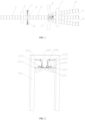
- FIG. 2 is a schematic structural diagram of the compensation assembly in FIG. 1 .
- the two compensation assemblies are oppositely arranged on two sides of the turnout beam 5.
- Each compensation assembly includes at least one compensation device 12.
- the compensation device 12 has an output part, and the output part of the compensation device 12 is operatively inserted into the gap between the first end of the turnout beam 5 and the end of the base rail beam 1 facing the turnout beam 5, so that the gap between the base rail beam 1 and the turnout beam 5 can be filled to ensure the reliability of the running of a rail vehicle across the base rail beam 1 and the turnout beam 5.
- the compensation device 12 includes a compensation beam 122, which is the output part of the compensation device, and the compensation beam 122 operatively moves in a direction perpendicular to the base rail beam 1.
- the first transition pier column 3 may include two opposite support columns 301.
- An inner side of the support column 301 is provided with a support seat 302 corresponding to the compensation device 12, and the compensation device 12 further includes a fixed seat 302 and a driving unit 125.
- the fixed seat 302 is secured on a corresponding support seat 302.
- a fixed end of the driving unit 125 is secured on the fixed seat 302, the output end of the driving unit 125 can be telescopically moved back and forth along a horizontal direction, and the output end of the driving unit 125 is fixedly connected to the compensation beam 122.
- the compensation beam 122 needs to compensate the gap between the base rail beam 1 and the turnout beam 5
- the output end of the driving unit 125 can drive the compensation beam 122 to move to implement the compensation.
- the driving unit 125 there can be two driving units 125 disposed opposite to each other in the horizontal direction, and the two driving units 125 move synchronously to make the compensation beam 122 move in a predetermined direction.
- the driving unit 125 may be a linear reciprocating motion mechanism such as an electric push rod, a hydraulic cylinder, etc., which is not limited in the present disclosure.
- the support seat 302 may be provided with a guide rail, and the bottom of the compensation beam 122 is provided with a roller wheel 128.
- the roller wheel 128 is rollable and disposed on the guide rail to reduce friction and improve the swiftness of the operation of the compensation beam 122.
- the bottom of the support seat 302 may be provided with a reinforcing plate 303, and the reinforcing plate 303 is connected with the support column 301 on the same side to improve the bearing capacity of the support seat 302.
- the inner side of the support column 301 is provided with a guiding plate 304 corresponding to the compensation device 12.
- the bottom of the guiding plate 304 is provided with a slide channel, and the top of the compensation beam 122 is slidably arranged in the slide channel of the corresponding guiding plate 304 to guide the movement of the compensation beam 122.
- the first transition pier column 3 also include a top beam 305 connecting the two opposite support columns 301 together, and a connection plate 306 is provided between the top of the guiding plate 304 and the top beam 305 to improve the reliability of installation of the guiding plate 304.
- each compensation device 12 is provided with one corresponding locking device.
- the locking device includes a positioning seat 126, a telescopic mechanism and a positioning pin 127.
- the positioning seat 126 is fixedly arranged on the corresponding compensation beam 122.
- the positioning seat 126 is provided with a locking hole.
- the telescopic mechanism is fixedly arranged on the first transition pier column 3.
- the positioning pin 127 has a first end and a second end opposite to each other.
- the first end of the positioning pin 127 is fixedly connected to the output end of the telescopic mechanism, and the second end of the positioning pin 127 is operatively inserted into the locking hole on the positioning seat 126.
- the telescopic mechanism is operated to move so that the second end of the positioning pin 127 is inserted into the locking hole on the positioning seat 126, and thus the compensation beam 122 can be locked.
- the positioning seat 126 is preferably arranged at the outer bottom of the compensation beam 122, and preferably there are two locking holes on the positioning seat 126, and the two positioning holes are respectively located on two sides of the compensation beam 122, so that the compensation beam 122 can be locked from two directions to improve the reliability of locking.
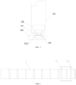
- FIG. 3 is a schematic diagram of the arrangement of the locking device in FIG. 2 .
- two telescopic mechanisms 1210 are provided inside the support seat 302, and the output ends of the two telescopic mechanisms 1210 are both vertically telescopic.
- the axial direction of the locking hole on the positioning seat 126 is vertical.
- the positioning pin 127 connected to the output end of the telescopic mechanism 1210 can be inserted into the locking hole on the positioning seat 126.
- the two telescopic mechanisms 1210 can also be arranged on the top of the support seat 302.
- the telescopic end of the telescopic mechanism 1210 moves in the horizontal direction, and the axial direction of the locking hole on the positioning seat 126 is in the horizontal direction.
- the positioning pin 127 connected to the output end of the telescopic mechanism 1210 can be inserted into the locking hole on the positioning seat 126.
- the output end of the telescopic mechanism is in a retracted state, so that the operation of the compensation beam 122 is not affected.
- a support plate 129 is provided on the inner side of the beam 122.
- the support plate 129 is used to support the traveling wheels of the rail vehicle to pass, and the inner side of the compensation beam 122 above the support plate 129 is used to support a guiding wheel of the rail vehicle to adapt to the smooth passage of the rail vehicle with the guiding wheel.
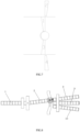
- FIG. 4 is a schematic assembly diagram of the turnout beam and the traveling mechanism
- FIG. 5 is a schematic structural diagram of the traveling mechanism.
- the traveling mechanism 11 includes a traveling track 117 and a traveling unit.
- the traveling track 117 is arc-shaped, and a center of the arc-shaped traveling track 117 is located on the center line of the center pin 4.
- the second end of the turnout beam 5 is connected to the traveling unit.
- the traveling unit can operatively travel on the traveling track 117, so that the first end of the turnout beam 5 is rotated by a certain angle around the center pin. That makes the turnout beam 5 connect with the branch rail beam of a branch to be guided, and then the key action of switching the turnout beam is completed.
- the traveling unit includes a first side frame 111 and a second side frame 115 arranged oppositely. An end of the first side frame 111 and a corresponding end of the second side frame 115 are connected by connecting beams 116. There are mounting grooves 118 provided on both sides of the bottom of the first side frame 111 and the second side frame 115, and the second end of the turnout beam 5 are fixedly connected in the mounting grooves 118 at the bottom of the first side frame 111 and the second side frame 115 in turn to realize the assembly of the second end of the turnout beam 5 and the traveling unit.
- the first side frame 111, the second side frame 115 and the connecting beam 11 constituting the traveling unit are preferably integrally formed, so that the traveling unit has sufficient bearing strength.
- the traveling unit further includes a drive motor 114 and a plurality of wheel shafts 113.
- the tops of the first side frame 111 and the top of the second side frame 115 are connected by the plurality of wheel shafts 113 arranged at intervals.
- One wheel shaft 113 among the plurality of wheel shafts 113 is provided with a drive wheel 119, and the remaining wheel shafts 113 of the plurality of wheel shafts 113 are provided with driven wheels 112. Both the drive wheel 119 and the driven wheels 112 are rollablely arranged on the traveling track 117.
- the drive motor 114 is fixedly disposed on the outside of the second side frame 115.
- the output shaft of the drive motor 114 is connected with the wheel shaft 113 on which the drive wheel 119 is mounted, so that the drive motor 114 can drive the wheel shaft 113 on which the drive wheel 119 is mounted to rotate, thereby driving the drive wheel 119 on the wheel shaft 113 to rotate on the traveling track 117 to realize the movement of the traveling unit on the traveling track 117, and the movement of the traveling unit can drive the plurality of driven wheels 112 to roll on the traveling track 117 to balance the movement of the traveling unit.
- the drive wheel 119 is located on a middle wheel shaft 113 among the plurality of wheel shafts 113, and the way of one drive wheel 119 cooperating with the plurality of driven wheels 112 can simplify the structure and optimize the space.
- each wheel shaft may also be provided with multiple wheels, so as to further improve the balance performance of the movement of the traveling unit, and the drive motor can rotate in forward and reverse directions to ensure that the turnout beam swings from side to side around the center rotating device upon switching.
- the drive motor is not the only way to drive.
- an electric push rod can be used to drive, or a slide rail can be mounted on the side of the turnout beam to cooperate with a rotating arm to drive, which is not limited in the present disclosure.
- the working principle of the rail transit turnout system is as follows: Switching process: Taking the three-way turnout as an example, it is assumed that an initial position of the turnout beam is a straight position as shown in the state in FIG. 1 , and an initial position of the compensation beam is all pulled out of the turnout beam, i.e., in a standby position.
- the compensation beam enters the gap between the turnout beam 5 and the base rail beam 1 to completely compensate it. At this time, the position of the compensation beam is a compensation position.
- the arrangement of the compensation beam is as shown in FIG 6 . Referring to FIG. 6 , there are four compensation beams, respectively, No. 1 compensation beam 121, No. 2 compensation beam 122, No. 3 compensation beam 123 and No.
- No. 1 compensation beam 121 and No. 2 compensation beam 122 are a group of compensation beams, and No. 3 compensation beam 123 and No. 4 compensation beam 124 are another group of compensation beams.
- the two groups of compensation beams are respectively located on two sides of the gap between the turnout beam 5 and the base rail beam 1.
- the compensation device, locking device, and traveling mechanism have their own control logic and can act independently, thus having the characteristics of automatic operation.
- the rail transit turnout system shown in the present disclosure is simple and reliable in operation, can effectively shorten the switching time, improve the transportation efficiency, and has good practical value.
Landscapes
- Engineering & Computer Science (AREA)
- Mechanical Engineering (AREA)
- Architecture (AREA)
- Civil Engineering (AREA)
- Structural Engineering (AREA)
- Railway Tracks (AREA)
- Train Traffic Observation, Control, And Security (AREA)
Abstract
Description
- The present disclosure relates to the technical field of rail transit systems, and in particular, to a rail transit turnout system.
- The suspended monorail system is a kind of in-air rail transportation system. It has the advantages of good compatibility, high safety, high integration, low cost, flexible lines, environment friendly and low noise, etc. It meets the needs of modern urban rail transportation and is widely used in new type urban rail construction of China.
- At present, domestic suspended monorail traffic turnouts are mainly simple turnout. There are two types of multi-way turnout disclosed in practical applications, respectively translational beam replacement type and segmental type. The translational beam replacement type turnout completes line conversion between a straight traveling state and a curve traveling state by parallel movement of a branch rail beam and a curved rail beam. The segmental type turnout consists of a fixed beam, a driving beam and a driven beam, which makes the vehicle travel on a gently folding line approximate to an arc curve by mechanically driving the driving beam and the driven beam to be switched integrally using an electric motor mounted on the driving beam.
- In the suspended rail transit system, the translational beam replacement type multi-way turnout has cumbersome structure, requires high strength of pier column and related mechanisms, and has disadvantages such as requiring high switching power, long switching time, poor in economy. When the segmental type turnout is switched, the turnout beam is a multi-section broken-line beam, and there are many pier column foundations; at the same time, there are high requirement for the precision of the electric motor, and the reliability is poor.
- Therefore, the existing technology needs to be improved.
- In view of the above-mentioned deficiencies in the prior art, the present disclosure provides a rail transit turnout system to solve the problem that the translational beam replacement type multi-way turnout in the suspended rail transit system has cumbersome structure, requires high strength of pier column and related mechanisms, and has disadvantages such as requiring high switching power, long switching time, poor in economy and the problem that the turnout beam is a multi-section broken-line beam when the segmental type turnout is switched, and there are many pier column foundations; at the same time, there are high requirement for the precision of the electric motor, and the reliability is poor.
- The rail transit turnout system according to the present disclosure is charactered by comprising: a base rail beam fixedly supported by a plurality of base pier columns arranged at intervals; a turnout beam having a first end and a second end opposite to each other, wherein the first end of the turnout beam is provided on a first transition pier column and is rotatably connected to the first transition pier column through a center pin, the center pin is arranged vertically, and the second end of the turnout beam is provided on a second transition pier column and is capable of traveling on the second transition pier column; and branch rail beams, wherein there are at least two branch rail beams, the branch rail beams are fixedly supported by a plurality of branch pier columns arranged at intervals, each of the branch rail beams has a first end and a second end opposite to each other, the turnout beam is arranged between the base rail beam and the branch rail beams, the first end of the turnout beam docks with an end of the base rail beam facing the turnout beam, the second end of the turnout beam operatively selects to dock with a first end of one branch rail beam among the branch rail beams, and the second end of each branch rail beam extends in a direction away from the turnout beam.
- In some embodiments, the first transition pier column is provided with two compensation assemblies, the two compensation assemblies are oppositely disposed on two sides of the turnout beam, and each compensation assembly includes at least one compensation device, the compensation device has an output part, and the output part of the compensation device is operatively inserted into a gap between the first end of the turnout beam and the end of the base rail beam facing the turnout beam.
- In some embodiments, the compensation device includes a compensation beam, wherein the compensation beam is the output part of the compensation device, and the compensation beam is operatively movable in a direction perpendicular to the base rail beam.
- In some embodiments, the first transition pier column includes two opposite support columns, and an inner side of the support column is provided with a support seat corresponding to the compensation device; the compensation device includes a fixed seat and a driving unit, the fixed seat is fixedly disposed on the corresponding support seat, and a fixed end of the driving unit is fixedly disposed on the fixed seat, an output end of the driving unit is capable of telescopically moving back and forth along a horizontal direction, and the output end of the driving unit is fixedly connected with the compensation beam.
- In some embodiments, the support seat is provided with a guide rail; and the bottom of the compensation beam is provided with a roller wheel, and the roller wheel is rollablely disposed on the guide rail.
- In some embodiments, an inner side of the support column is provided with a guiding plate corresponding to the compensation device, and the bottom of the guiding plate is provided with a slide channel, and the top of the compensation beam is slidably disposed in the slide channel of the corresponding guiding plate.
- In some embodiments, the system further includes a locking device, each compensation device is correspondingly configured with one locking device, and the locking device includes: a positioning seat fixedly disposed on the corresponding compensation beam and provided with a locking hole; a telescopic mechanism fixedly disposed on the first transition pier column; and a positioning pin, wherein the positioning pin has a first end and a second end opposite to each other, the first end of the positioning pin is fixedly connected to an output end of the telescopic mechanism, and the second end of the positioning pin is operatively inserted into the locking hole on the positioning seat.
- In some embodiments, the second end of the turnout beam travels on the second transition pier column using a traveling mechanism, and the traveling mechanism includes: a traveling track, wherein the traveling track is arc-shaped, and a center of the arc-shaped traveling track is located on a central line of the center pin; and a traveling unit, wherein the second end of the turnout beam is connected to the traveling unit, and the traveling unit operatively travels on the traveling track.
- In some embodiments, the traveling unit includes a first side frame and a second side frame arranged opposite to each other, an end of the first side frame and a corresponding end of the second side frame are connected by connecting beams, bottoms of the first side frame and the second side frame are respectively provided with installation grooves, and the second end of the turnout beam is sequentially fixedly connected in the installation grooves at the bottoms of the first side frame and the second side frame.
- In some embodiments, the traveling unit further includes: a plurality of wheel shafts arranged at intervals and configured to connect tops of the first side frame and the second side frame, wherein one of the plurality of the wheel shafts is provided with a drive wheel, and the drive wheel is rollablely disposed on the traveling track; and a drive motor fixedly disposed on an outer side of the second side frame, wherein an output shaft of the drive motor is fixedly connected with the one of the plurality of wheel shafts.
- With the rail transit turnout system provided by the present disclosure, since the first end of the turnout beam docks with the end of the base rail beam facing the turnout beam, the first end of the turnout beam is rotatably disposed on the first transition pier column, and the second end of the turnout beam operatively selects to dock with the first end of a certain branch rail beam, the purpose of switching can be achieved by operating the rotation of the first end of the turnout beam on the first transition pier column.
- Compared with the translational beam replacement type multi-way turnout, the present disclosure adopts a piece of turnout beam as the main body of the turnout, which has a short length and can greatly reduce the mass of the multi-way turnout beam in the prior art, and at the same time the volume and mass of the pier column are reduced and the cost is reduced.
- Compared with the segment type multi-way turnout, the present disclosure has only one broken-line segment, and needs only two transition pier column beams, which has higher reliability and lower cost.
- The rail transit turnout system disclosed in the present disclosure is simple and reliable in operation, can effectively shorten the switching time, improves the transportation efficiency, and has good practical value.
-
-
FIG. 1 is a schematic structural diagram of a rail transit turnout system according to an embodiment of the present disclosure. -
FIG. 2 is a schematic structural diagram of a compensation assembly inFIG. 1 . -
FIG. 3 is a schematic diagram showing the arrangement of a locking device ofFIG. 2 . -
FIG. 4 is a schematic assembly diagram of a turnout beam and a traveling mechanism. -
FIG. 5 is a schematic structural diagram of a traveling mechanism. -
FIG. 6 is a schematic diagram showing a state in which a compensation beam is in a standby position. -
FIG. 7 is a schematic diagram showing a state in which the No. 1 compensation beam and the No. 3 compensation beam are in the compensation position. -
FIG. 8 is a schematic diagram showing a state in which a turnout beam is switched to a left turn position. -
FIG. 9 is a schematic diagram showing a state in which the No. 3 compensation beam and the No. 4 compensation beam are in the compensation position. -
FIG. 10 is a schematic diagram of a state in which the turnout beam is switched to the right turn position. -
FIG. 11 is a schematic diagram showing a state in which the No. 1 compensation beam and the No. 2 compensation beam are in the compensation position. -
FIG. 1 is a schematic structural diagram of a rail transit turnout system according to an embodiment of the present disclosure. With reference toFIG. 1 , the system includes abase rail beam 1, aturnout beam 5 and branch rail beams, wherein thebase rail beam 1 is fixedly supported by a plurality of base pier column 2 arranged at intervals, and theturnout beam 5 has a first end and a second end opposite to each other. The first end of theturnout beam 5 is disposed on a first transition pier column 3, and the first end of theturnout beam 5 is rotatably connected to the first transition pier column 3 through acenter pin 4 which is arranged vertically. The second end of theturnout beam 5 is disposed on a second transition pier column 6, and the second end of theturnout beam 5 can travel on the second transition pier column 6. There are at least two branch rail beams. The branch rail beams are fixedly supported by a plurality of branch pier columns 7 arranged at intervals, and each branch rail beam has a first end and a second end opposite to each other. Theturnout beam 5 is arranged between thebase rail beam 1 and the branch rail beams, the first end of theturnout beam 5 docks with an end of thebase rail beam 1 facing theturnout beam 5, and the second end of theturnout beam 5 operatively selects to dock with the first end of a certain one of the branch rail beams. The second ends of the branch rail beams extend in a direction away from theturnout beam 5. - In actual operation, the purpose of switching can be achieved by operating the rotation of the first end of the
turnout beam 5 on the first transition pier column 3. Compared with the translational beam replacement type multi-way turnout, the present disclosure adopts a piece of turnout beam as the main body of the turnout, which has a short length and can greatly reduce the mass of the multi-way turnout beam in the prior art, and at the same time the volume and mass of the pier column are reduced and the cost is reduced. Compared with the segmental type multi-way turnout, the present disclosure has only one broken-line segment, and needs only two transition pier column beams, which has higher reliability and lower cost. - In some embodiments, there can be three branch rail beams, respectively a first branch rail beam 8, a second branch rail beam 9 and a third
branch rail beam 10. The first branch rail beam 8 and the thirdbranch rail beam 10 are respectively arranged on two sides of the second branch rail beam 9. The second branch rail beam 9 and thebase rail beam 1 are positioned in a same line. The first branch rail beam 8, the second branch rail beam 9 and the thirdbranch rail beam 10 are arranged in a fan shape. - Referring to
FIG. 1 , first ends of the plurality of branch rail beams can be fixedly supported by one branch pier column 7. - In order to adapt to the rotation of the turnout beam, there needs to be a gap between the
base rail beam 1 and theturnout beam 5, which is not conducive to the running of a rail vehicle across thebase rail beam 1 and theturnout beam 5. In order to solve this problem, the present disclosure provides a compensation assembly. -
FIG. 2 is a schematic structural diagram of the compensation assembly inFIG. 1 . Combined withFIG. 2 , there are two compensation assemblies disposed on the first transition pier column 3. The two compensation assemblies are oppositely arranged on two sides of theturnout beam 5. Each compensation assembly includes at least onecompensation device 12. Thecompensation device 12 has an output part, and the output part of thecompensation device 12 is operatively inserted into the gap between the first end of theturnout beam 5 and the end of thebase rail beam 1 facing theturnout beam 5, so that the gap between thebase rail beam 1 and theturnout beam 5 can be filled to ensure the reliability of the running of a rail vehicle across thebase rail beam 1 and theturnout beam 5. - Combined with
FIG. 2 , thecompensation device 12 includes acompensation beam 122, which is the output part of the compensation device, and thecompensation beam 122 operatively moves in a direction perpendicular to thebase rail beam 1. - Combined with
FIG. 2 , the first transition pier column 3 may include twoopposite support columns 301. An inner side of thesupport column 301 is provided with asupport seat 302 corresponding to thecompensation device 12, and thecompensation device 12 further includes a fixedseat 302 and adriving unit 125. The fixedseat 302 is secured on acorresponding support seat 302. A fixed end of thedriving unit 125 is secured on the fixedseat 302, the output end of thedriving unit 125 can be telescopically moved back and forth along a horizontal direction, and the output end of thedriving unit 125 is fixedly connected to thecompensation beam 122. When thecompensation beam 122 needs to compensate the gap between thebase rail beam 1 and theturnout beam 5, the output end of thedriving unit 125 can drive thecompensation beam 122 to move to implement the compensation. - In some embodiments, there can be two driving
units 125 disposed opposite to each other in the horizontal direction, and the two drivingunits 125 move synchronously to make thecompensation beam 122 move in a predetermined direction. The drivingunit 125 may be a linear reciprocating motion mechanism such as an electric push rod, a hydraulic cylinder, etc., which is not limited in the present disclosure. - In some embodiments, combined with
FIG. 2 , thesupport seat 302 may be provided with a guide rail, and the bottom of thecompensation beam 122 is provided with aroller wheel 128. Theroller wheel 128 is rollable and disposed on the guide rail to reduce friction and improve the swiftness of the operation of thecompensation beam 122. - Combined with
FIG. 2 , in some embodiments, the bottom of thesupport seat 302 may be provided with a reinforcingplate 303, and the reinforcingplate 303 is connected with thesupport column 301 on the same side to improve the bearing capacity of thesupport seat 302. - Combined with
Fig. 2 , in some embodiments, the inner side of thesupport column 301 is provided with a guidingplate 304 corresponding to thecompensation device 12. The bottom of the guidingplate 304 is provided with a slide channel, and the top of thecompensation beam 122 is slidably arranged in the slide channel of the corresponding guidingplate 304 to guide the movement of thecompensation beam 122. - Combined with
FIG. 2 , the first transition pier column 3 also include atop beam 305 connecting the twoopposite support columns 301 together, and aconnection plate 306 is provided between the top of the guidingplate 304 and thetop beam 305 to improve the reliability of installation of the guidingplate 304. - When the
compensation beam 122 is operated to reach the gap between thebase rail beam 1 and theturnout beam 5, in order to prevent thecompensation beam 122 from returning, eachcompensation device 12 is provided with one corresponding locking device. Combined withFIG. 2 , the locking device includes apositioning seat 126, a telescopic mechanism and apositioning pin 127. Thepositioning seat 126 is fixedly arranged on thecorresponding compensation beam 122. Thepositioning seat 126 is provided with a locking hole. The telescopic mechanism is fixedly arranged on the first transition pier column 3. Thepositioning pin 127 has a first end and a second end opposite to each other. The first end of thepositioning pin 127 is fixedly connected to the output end of the telescopic mechanism, and the second end of thepositioning pin 127 is operatively inserted into the locking hole on thepositioning seat 126. After thecompensation beam 122 is compensated in place, the telescopic mechanism is operated to move so that the second end of thepositioning pin 127 is inserted into the locking hole on thepositioning seat 126, and thus thecompensation beam 122 can be locked. - In some embodiments, the
positioning seat 126 is preferably arranged at the outer bottom of thecompensation beam 122, and preferably there are two locking holes on thepositioning seat 126, and the two positioning holes are respectively located on two sides of thecompensation beam 122, so that thecompensation beam 122 can be locked from two directions to improve the reliability of locking. -
FIG. 3 is a schematic diagram of the arrangement of the locking device inFIG. 2 . Combined withFIG. 3 , twotelescopic mechanisms 1210 are provided inside thesupport seat 302, and the output ends of the twotelescopic mechanisms 1210 are both vertically telescopic. The axial direction of the locking hole on thepositioning seat 126 is vertical. By operating the telescopic mechanism, thepositioning pin 127 connected to the output end of thetelescopic mechanism 1210 can be inserted into the locking hole on thepositioning seat 126. - Of course, the two
telescopic mechanisms 1210 can also be arranged on the top of thesupport seat 302. The telescopic end of thetelescopic mechanism 1210 moves in the horizontal direction, and the axial direction of the locking hole on thepositioning seat 126 is in the horizontal direction. By operating the telescopic mechanism, thepositioning pin 127 connected to the output end of thetelescopic mechanism 1210 can be inserted into the locking hole on thepositioning seat 126. - It should be noted that, before the
compensation beam 122 is positioned in place, the output end of the telescopic mechanism is in a retracted state, so that the operation of thecompensation beam 122 is not affected. - Combined with
FIG. 2 , in some embodiments, asupport plate 129 is provided on the inner side of thebeam 122. Thesupport plate 129 is used to support the traveling wheels of the rail vehicle to pass, and the inner side of thecompensation beam 122 above thesupport plate 129 is used to support a guiding wheel of the rail vehicle to adapt to the smooth passage of the rail vehicle with the guiding wheel. - Combined with
FIG. 1 , the second end of theturnout beam 5 travels on the second transition pier column 6 through a travelingmechanism 11.FIG. 4 is a schematic assembly diagram of the turnout beam and the traveling mechanism, andFIG. 5 is a schematic structural diagram of the traveling mechanism. Referring toFIGS. 1 ,4 and5 , the travelingmechanism 11 includes a traveling track 117 and a traveling unit. The traveling track 117 is arc-shaped, and a center of the arc-shaped traveling track 117 is located on the center line of thecenter pin 4. The second end of theturnout beam 5 is connected to the traveling unit. The traveling unit can operatively travel on the traveling track 117, so that the first end of theturnout beam 5 is rotated by a certain angle around the center pin. That makes theturnout beam 5 connect with the branch rail beam of a branch to be guided, and then the key action of switching the turnout beam is completed. - Combined with
FIGS. 4 and5 , the traveling unit includes afirst side frame 111 and asecond side frame 115 arranged oppositely. An end of thefirst side frame 111 and a corresponding end of thesecond side frame 115 are connected by connectingbeams 116. There are mountinggrooves 118 provided on both sides of the bottom of thefirst side frame 111 and thesecond side frame 115, and the second end of theturnout beam 5 are fixedly connected in the mountinggrooves 118 at the bottom of thefirst side frame 111 and thesecond side frame 115 in turn to realize the assembly of the second end of theturnout beam 5 and the traveling unit. - The
first side frame 111, thesecond side frame 115 and the connectingbeam 11 constituting the traveling unit are preferably integrally formed, so that the traveling unit has sufficient bearing strength. - Combined with
FIG. 5 , the traveling unit further includes adrive motor 114 and a plurality ofwheel shafts 113. The tops of thefirst side frame 111 and the top of thesecond side frame 115 are connected by the plurality ofwheel shafts 113 arranged at intervals. Onewheel shaft 113 among the plurality ofwheel shafts 113 is provided with adrive wheel 119, and the remainingwheel shafts 113 of the plurality ofwheel shafts 113 are provided with drivenwheels 112. Both thedrive wheel 119 and the drivenwheels 112 are rollablely arranged on the traveling track 117. Thedrive motor 114 is fixedly disposed on the outside of thesecond side frame 115. The output shaft of thedrive motor 114 is connected with thewheel shaft 113 on which thedrive wheel 119 is mounted, so that thedrive motor 114 can drive thewheel shaft 113 on which thedrive wheel 119 is mounted to rotate, thereby driving thedrive wheel 119 on thewheel shaft 113 to rotate on the traveling track 117 to realize the movement of the traveling unit on the traveling track 117, and the movement of the traveling unit can drive the plurality of drivenwheels 112 to roll on the traveling track 117 to balance the movement of the traveling unit. - In some embodiments, the
drive wheel 119 is located on amiddle wheel shaft 113 among the plurality ofwheel shafts 113, and the way of onedrive wheel 119 cooperating with the plurality of drivenwheels 112 can simplify the structure and optimize the space. - It should be noted that, in some embodiments, each wheel shaft may also be provided with multiple wheels, so as to further improve the balance performance of the movement of the traveling unit, and the drive motor can rotate in forward and reverse directions to ensure that the turnout beam swings from side to side around the center rotating device upon switching. Of course, the drive motor is not the only way to drive. Alternatively, an electric push rod can be used to drive, or a slide rail can be mounted on the side of the turnout beam to cooperate with a rotating arm to drive, which is not limited in the present disclosure.
- The working principle of the rail transit turnout system is as follows:
Switching process:
Taking the three-way turnout as an example, it is assumed that an initial position of the turnout beam is a straight position as shown in the state inFIG. 1 , and an initial position of the compensation beam is all pulled out of the turnout beam, i.e., in a standby position. The compensation beam enters the gap between theturnout beam 5 and thebase rail beam 1 to completely compensate it. At this time, the position of the compensation beam is a compensation position. In this situation, the arrangement of the compensation beam is as shown inFIG 6 . Referring toFIG. 6 , there are four compensation beams, respectively, No. 1compensation beam 121, No. 2compensation beam 122, No. 3compensation beam 123 and No. 4compensation beam 124. No. 1compensation beam 121 and No. 2compensation beam 122 are a group of compensation beams, and No. 3compensation beam 123 and No. 4compensation beam 124 are another group of compensation beams. The two groups of compensation beams are respectively located on two sides of the gap between theturnout beam 5 and thebase rail beam 1. - Turnout straight position switching process: receives a straight position switching command → all compensation beams return to the standby position -> the traveling mechanism receives the command and drives the turnout beam to travel on the second transition pier column to make the turnout beam to switch to the straight position → after the turnout beam is switched into position, the No. 1 compensation beam and the No. 3 compensation beam receive a command and be pushed into the compensation position, and the compensation beams form a state shown in
FIG. 7 → after they are in place, the corresponding locking device acts to lock the compensation beam, and thus locking the switching → the switching is completed, waiting for the next switching command; - Turnout left turn position switching process: receives a left turn position switching command → all compensation beams return to the standby position -> the traveling mechanism receives the command and drives the turnout beam to travel on the second transition pier column to make the turnout beam to switch to a left turn position, forming a state shown in
FIG. 8 → after the turnout beam is switched into position, the No. 3 compensation beam and the No. 4 compensation beam receive a command, and then the No. 3 compensation beam and the No. 4 compensation beam are pushed into the compensation position, and the compensation beam forms a state as shown inFIG. 9 → after they are in place, the corresponding locking device acts to lock the compensation beam, and thus locking the switching → the switching is completed, waiting for the next switching command; - Turnout right turn position switching process: receives a right turn position switching command → all compensation beams return to a standby position → the traveling mechanism receives the command and drives the turnout beam to travel on the second transition pier column to make the turnout beam to switch to a right turn position, forming a state shown in
FIG. 10 → after the turnout beam is switched into place, the No. 1 compensation beam and the No. 2 compensation beam receive a command, and then the No. 1 compensation beam and the No. 2 compensation beam are pushed into the compensation position, and the compensation beams form a state as shown inFIG. 11 → after they are in place, the corresponding locking device acts to lock the compensation beam, and thus locking the switching → the switching is completed, waiting for the next switching command. - In some embodiments, the compensation device, locking device, and traveling mechanism have their own control logic and can act independently, thus having the characteristics of automatic operation.
- To sum up, the rail transit turnout system shown in the present disclosure is simple and reliable in operation, can effectively shorten the switching time, improve the transportation efficiency, and has good practical value.
- The above embodiments are preferred embodiments of the present disclosure, which are only used to facilitate the description of the present disclosure, and are not intended to limit the present disclosure in any form. Any equivalent embodiments obtained by those skilled in the art by making partial changes or modifications based on the technical contents disclosed in the present disclosure within the scope of the technical features of the present disclosure without departing from the technical features of the present disclosure, still belong to the scope of the technical features of the present disclosure.
Claims (10)
- A rail transit turnout system, charactered by comprising:a base rail beam fixedly supported by a plurality of base pier columns arranged at intervals;a turnout beam having a first end and a second end opposite to each other, wherein the first end of the turnout beam is provided on a first transition pier column and is rotatably connected to the first transition pier column through a center pin, the center pin is arranged vertically, and the second end of the turnout beam is provided on a second transition pier column and is capable of traveling on the second transition pier column; andbranch rail beams, wherein there are at least two branch rail beams, the branch rail beams are fixedly supported by a plurality of branch pier columns arranged at intervals, and each of the branch rail beams has a first end and a second end opposite to each other, the turnout beam is arranged between the base rail beam and the branch rail beams, the first end of the turnout beam docks with an end of the base rail beam facing the turnout beam, the second end of the turnout beam operatively selects to dock with a first end of one branch rail beam among the branch rail beams, and the second end of each branch rail beam extends in a direction away from the turnout beam.
- The rail transit turnout system according to claim 1, wherein the first transition pier column is provided with two compensation assemblies, the two compensation assemblies are oppositely disposed on two sides of the turnout beam, and each compensation assembly comprises at least one compensation device, the compensation device has an output part, and the output part of the compensation device is operatively inserted into a gap between the first end of the turnout beam and the end of the base rail beam facing the turnout beam.
- The rail transit turnout system according to claim 2, wherein the compensation device includes a compensation beam, the compensation beam is the output part of the compensation device, and the compensation beam is operatively movable in a direction perpendicular to the base rail beam.
- The rail transit turnout system according to claim 3, wherein the first transition pier column comprises two opposite support columns, and an inner side of the support column is provided with a support seat corresponding to the compensation device;wherein the compensation device comprises a fixed seat and a driving unit, the fixed seat is fixedly disposed on the corresponding support seat, and a fixed end of the driving unit is fixedly disposed on the fixed seat; andan output end of the driving unit is capable of telescopically moving back and forth along a horizontal direction, and the output end of the driving unit is fixedly connected with the compensation beam.
- The rail transit turnout system according to claim 4, wherein the support seat is provided with a guide rail; and
the bottom of the compensation beam is provided with a roller wheel, and the roller wheel is rollablely disposed on the guide rail. - The rail transit turnout system according to claim 5, wherein an inner side of the support column is provided with a guiding plate corresponding to the compensation device, and the bottom of the guiding plate is provided with a slide channel; and
the top of the compensation beam is slidably disposed in the slide channel of the corresponding guiding plate. - The rail transit turnout system according to claim 3, wherein the system further comprises a locking device, and each compensation device is correspondingly configured with one locking device, and the locking device comprises:a positioning seat fixedly disposed on the corresponding compensation beam and provided with a locking hole;a telescopic mechanism fixedly disposed on the first transition pier column;a positioning pin, wherein the positioning pin has a first end and a second end opposite to each other, the first end of the positioning pin is fixedly connected to an output end of the telescopic mechanism, and the second end of the positioning pin is operatively inserted into the locking hole on the positioning seat.
- The rail transit turnout system according to any one of claims 1-7, wherein the second end of the turnout beam travels on the second transition pier column using a traveling mechanism, and the traveling mechanism comprises:a traveling track, wherein the traveling track is an arc-shaped, and a center of the arc-shaped traveling track is located on a central line of the center pin; anda traveling unit, wherein the second end of the turnout beam is connected to the traveling unit, and the traveling unit operatively travels on the traveling track.
- The rail transit turnout system according to claim 8, wherein the traveling unit comprises a first side frame and a second side frame arranged opposite to each other, and an end of the first side frame and a corresponding end of the second side frame are connected by connecting beams, bottoms of the first side frame and the second side frame are respectively provided with installation grooves, and the second end of the turnout beam is sequentially fixedly connected in the installation grooves at the bottoms of the first side frame and the second side frame.
- The rail transit turnout system according to claim 9, wherein the traveling unit further comprises:a plurality of wheel shafts arranged at intervals and configured to connect tops of the first side frame and the second side frame, wherein one of the plurality of the wheel shafts is provided with a drive wheel, and the drive wheel is rollablely disposed on the traveling track;a drive motor fixedly disposed on an outer side of the second side frame, wherein an output shaft of the drive motor is fixedly connected with the one of the plurality of wheel shafts.
Applications Claiming Priority (2)
| Application Number | Priority Date | Filing Date | Title |
|---|---|---|---|
| CN202010893368.0A CN112127217B (en) | 2020-08-31 | 2020-08-31 | Rail transit turnout system |
| PCT/CN2021/112552 WO2022042338A1 (en) | 2020-08-31 | 2021-08-13 | Rail transit turnout system |
Publications (1)
| Publication Number | Publication Date |
|---|---|
| EP4206402A1 true EP4206402A1 (en) | 2023-07-05 |
Family
ID=73848717
Family Applications (1)
| Application Number | Title | Priority Date | Filing Date |
|---|---|---|---|
| EP21860177.1A Pending EP4206402A1 (en) | 2020-08-31 | 2021-08-13 | Rail transit turnout system |
Country Status (5)
| Country | Link |
|---|---|
| EP (1) | EP4206402A1 (en) |
| JP (1) | JP2023538168A (en) |
| CN (1) | CN112127217B (en) |
| AU (1) | AU2021334603B2 (en) |
| WO (1) | WO2022042338A1 (en) |
Families Citing this family (8)
| Publication number | Priority date | Publication date | Assignee | Title |
|---|---|---|---|---|
| CN110468636B (en) * | 2019-08-30 | 2024-04-02 | 北京起重运输机械设计研究院有限公司 | Circuit switching device |
| CN112127217B (en) * | 2020-08-31 | 2022-03-01 | 中车长江车辆有限公司 | Rail transit turnout system |
| CN112853822A (en) * | 2021-03-16 | 2021-05-28 | 中国铁建重工集团股份有限公司 | Switch assembly and control method of switch assembly |
| CN113062152B (en) * | 2021-03-16 | 2022-02-11 | 中国铁建重工集团股份有限公司 | Switch assembly |
| CN113353794B (en) * | 2021-06-04 | 2022-06-24 | 中交二航局第二工程有限公司 | Seamless connection track capable of being horizontally bent |
| CN114013472A (en) * | 2021-11-18 | 2022-02-08 | 中铁宝桥集团有限公司 | Suspension type track list opens vehicle system of changing wire |
| CN117188221A (en) * | 2022-05-31 | 2023-12-08 | 比亚迪股份有限公司 | Switch and rail transit system |
| CN117188220A (en) * | 2022-05-31 | 2023-12-08 | 比亚迪股份有限公司 | Switch, crossover switch and rail transit system |
Family Cites Families (14)
| Publication number | Priority date | Publication date | Assignee | Title |
|---|---|---|---|---|
| JPS549408U (en) * | 1977-06-21 | 1979-01-22 | ||
| JPH04111801A (en) * | 1990-08-31 | 1992-04-13 | H S S T:Kk | Switch device for beam-type track |
| EP0829578A3 (en) * | 1996-09-16 | 1998-05-13 | Wergles, Marx | Point for monorail transporting system |
| DE102012002912A1 (en) * | 2012-02-14 | 2013-08-14 | Volkswagen Aktiengesellschaft | conveyor |
| CN105040533B (en) * | 2015-08-07 | 2017-04-19 | 中铁工程设计咨询集团有限公司 | Pivot type turnout structure and turnout switching method |
| CN105839482B (en) * | 2016-05-31 | 2017-06-30 | 西南石油大学 | Suspension type sky row rail switch in a kind of beam |
| CN105951542B (en) * | 2016-06-13 | 2017-11-03 | 陈刚 | Track becomes rail system |
| CN208530595U (en) * | 2018-06-26 | 2019-02-22 | 比亚迪股份有限公司 | Interior guide type track switch and the Rail Transit System with it |
| CN209307792U (en) * | 2018-10-25 | 2019-08-27 | 中铁工程机械研究设计院有限公司 | Suspension type monorail track switch swing type compensates rail device |
| CN110714376A (en) * | 2019-09-29 | 2020-01-21 | 深圳空铁科技股份有限公司 | Turnout mechanism for suspension type rail transit transportation system |
| CN111172821A (en) * | 2020-01-07 | 2020-05-19 | 中铁工程设计咨询集团有限公司 | Suspension type single-rail single-shaft single-beam flat-turning turnout |
| CN111139692B (en) * | 2020-01-21 | 2024-07-12 | 曾鉴 | Rail beam turnout mechanism for rail transit |
| CN112127217B (en) * | 2020-08-31 | 2022-03-01 | 中车长江车辆有限公司 | Rail transit turnout system |
| CN112127218B (en) * | 2020-08-31 | 2022-03-25 | 中车长江车辆有限公司 | Compensation device |
-
2020
- 2020-08-31 CN CN202010893368.0A patent/CN112127217B/en active Active
-
2021
- 2021-08-13 EP EP21860177.1A patent/EP4206402A1/en active Pending
- 2021-08-13 AU AU2021334603A patent/AU2021334603B2/en active Active
- 2021-08-13 WO PCT/CN2021/112552 patent/WO2022042338A1/en unknown
- 2021-08-13 JP JP2022564535A patent/JP2023538168A/en active Pending
Also Published As
| Publication number | Publication date |
|---|---|
| CN112127217A (en) | 2020-12-25 |
| AU2021334603B2 (en) | 2024-05-30 |
| AU2021334603A1 (en) | 2022-12-01 |
| CN112127217B (en) | 2022-03-01 |
| JP2023538168A (en) | 2023-09-07 |
| WO2022042338A1 (en) | 2022-03-03 |
Similar Documents
| Publication | Publication Date | Title |
|---|---|---|
| EP4206402A1 (en) | Rail transit turnout system | |
| CN112127218B (en) | Compensation device | |
| CN108454651B (en) | Straddle type monorail replacement Liang Shan crossover turnout equipment | |
| CN109208398B (en) | Switch and straddle type track system | |
| CN108589438B (en) | Magnetic suspension turnout | |
| WO2022105284A1 (en) | Recessed-bottom transversely moving-type turnout | |
| CN113104133B (en) | Unmanned delivery vehicle | |
| CN111535085B (en) | Suspension type single-rail turnout | |
| CN108657226B (en) | Turnout switch actuating mechanism and straddle type monorail with same | |
| CN207391948U (en) | A kind of lifting type Riding-type Monorail Switch beam of hydraulic-driven | |
| US3659529A (en) | Improved transportation system | |
| US3902428A (en) | Tracked vehicle systems | |
| CN215946030U (en) | Synchronous transfer mechanism of transformer | |
| CN112429036B (en) | Straddle type single-rail synchronous beam-changing turnout | |
| CN113062153B (en) | Track turnout | |
| CN112301809B (en) | Single-track switch, single-track with single-track switch and track traffic system | |
| CN210797124U (en) | Turnout mechanism for suspension type rail transit transportation system | |
| CN212375640U (en) | Switch device | |
| CN118082915A (en) | Flexible driving device for guide rail and turnout | |
| CN112918503B (en) | Rail vehicle and rail vehicle sliding table thereof | |
| CN217351959U (en) | Autonomous guiding device and guiding system for air train | |
| CN220029232U (en) | Turnover mechanism for processing main girder plates of steel plate girder | |
| CN221297451U (en) | Automatic rail changing device between straight rail and bent rail of endless rope winch | |
| CN112501963B (en) | Straddle type single-rail four-line cross turnout | |
| CN219010826U (en) | Bidirectional combined turnout and track system |
Legal Events
| Date | Code | Title | Description |
|---|---|---|---|
| STAA | Information on the status of an ep patent application or granted ep patent |
Free format text: STATUS: THE INTERNATIONAL PUBLICATION HAS BEEN MADE |
|
| PUAI | Public reference made under article 153(3) epc to a published international application that has entered the european phase |
Free format text: ORIGINAL CODE: 0009012 |
|
| STAA | Information on the status of an ep patent application or granted ep patent |
Free format text: STATUS: REQUEST FOR EXAMINATION WAS MADE |
|
| 17P | Request for examination filed |
Effective date: 20230321 |
|
| AK | Designated contracting states |
Kind code of ref document: A1 Designated state(s): AL AT BE BG CH CY CZ DE DK EE ES FI FR GB GR HR HU IE IS IT LI LT LU LV MC MK MT NL NO PL PT RO RS SE SI SK SM TR |
|
| DAV | Request for validation of the european patent (deleted) | ||
| DAX | Request for extension of the european patent (deleted) | ||
| REG | Reference to a national code |
Ref country code: DE Ref legal event code: R079 Free format text: PREVIOUS MAIN CLASS: E01B0025100000 Ipc: E01B0025120000 |