EP4206375A1 - Customer accessible lint filter - Google Patents
Customer accessible lint filter Download PDFInfo
- Publication number
- EP4206375A1 EP4206375A1 EP22203978.6A EP22203978A EP4206375A1 EP 4206375 A1 EP4206375 A1 EP 4206375A1 EP 22203978 A EP22203978 A EP 22203978A EP 4206375 A1 EP4206375 A1 EP 4206375A1
- Authority
- EP
- European Patent Office
- Prior art keywords
- lint
- dryer
- catcher
- combination washer
- retention mechanism
- Prior art date
- Legal status (The legal status is an assumption and is not a legal conclusion. Google has not performed a legal analysis and makes no representation as to the accuracy of the status listed.)
- Withdrawn
Links
Images



Classifications
-
- D—TEXTILES; PAPER
- D06—TREATMENT OF TEXTILES OR THE LIKE; LAUNDERING; FLEXIBLE MATERIALS NOT OTHERWISE PROVIDED FOR
- D06F—LAUNDERING, DRYING, IRONING, PRESSING OR FOLDING TEXTILE ARTICLES
- D06F58/00—Domestic laundry dryers
- D06F58/20—General details of domestic laundry dryers
- D06F58/22—Lint collecting arrangements
-
- D—TEXTILES; PAPER
- D06—TREATMENT OF TEXTILES OR THE LIKE; LAUNDERING; FLEXIBLE MATERIALS NOT OTHERWISE PROVIDED FOR
- D06F—LAUNDERING, DRYING, IRONING, PRESSING OR FOLDING TEXTILE ARTICLES
- D06F25/00—Washing machines with receptacles, e.g. perforated, having a rotary movement, e.g. oscillatory movement, the receptacle serving both for washing and for centrifugally separating water from the laundry and having further drying means, e.g. using hot air
Definitions
- the present disclosure relates to household appliances, generally those including a combination washer/dryer and, more particularly, an accessible lint filter.
- lint screen In household appliances, such as washers, dryers, and combination washer/dryers, it is desirable to remove lint during operating cycles from these machines. Particularly, in dryers, a lint screen or the like is present to catch the lint as it circulates within the drying appliance during operating cycles. Different types of lint screens have been provided by manufacturers. These types of screens are ones that are accessible upon opening the door of the dryer and those that can be removed from outside of the cabinet enabling withdrawal of the lint screen for cleaning. These types of lint screens are satisfactory for their intended purposes. However, designers strive to improve the art.
- the present disclosure provides the art with a lint filter assembly that is positively held within the cabinet.
- the lint filter assembly provides an easily removable lint filter assembly with a positive action to maintain the lint filter assembly within the cabinet.
- the action may be mechanical or magnetic.
- the lint filter assembly provides a lid that enables easy removal of the lint from the filter. Additionally, the assembly provides a utility space for various items such as pods, dryer sheets, brushes or the like.
- a lint filter assembly for a household appliance comprising a housing for coupling with duct work of the appliance.
- a filter assembly is receivable in the housing.
- the filter assembly collects lint as is moved through the duct work.
- a mechanism is coupled with the filter assembly so that a user pushes the filter assembly into the housing into a first position where the filter assembly is positively locked and retained by the mechanism.
- the filter assembly is moved to a second clean out position, releasing the positive lock so that lint can be removed from the lint filter assembly.
- the mechanism may be a push/push mechanism including a grab latch or a magnetic latch.
- the mechanism is a magnetic seal position on the filter assembly for magnetically locking the filter assembly in the first position.
- the filter assembly includes a cover with the magnetic seal for locking with a cabinet.
- the lint filter assembly includes a catch with a frame with a screen where the frame is two pieces with a bowl and a cover.
- the bowl or cover includes a metal piece and the other includes a magnet.
- the bowl and cover are co-molded.
- the cover or lid includes a lint peeler.
- the frame also includes a storage area for various items.
- a combination washer/dryer comprising a cabinet, a tub positioned inside the cabinet, a rotatable drum positioned inside the tub, a washing circuit that is coupled with the tub, and a drying circuit that is coupled with the tub for moving heated air into the drum.
- the drying circuit includes duct work that directs the heated air through the cabinet.
- a lint filter assembly including a housing is coupled with the duct work and receives a lint catcher for collecting lint as it moves through the duct work.
- a retention mechanism is coupled with the lint filter assembly such that a user pushes the lint catcher into the housing for retaining the lint catcher in a first position where the lint catcher is positively locked in place by the retention mechanism and the user pushes the lint catcher further into the housing to a second position for releasing the retention mechanism so that the lint catcher can be removed from the lint filter assembly.
- the retention mechanism is a push/push mechanism that includes either a mechanism grab latch device or a magnetic device.
- the retention mechanism may include a magnetic strip positioned on the lint filter assembly for magnetically locking the lint catcher in the first position.
- the lint catcher may include a cover with a seal and the seal may include a pocket that retains the magnetic strip.
- the magnetic strip provides a positive retention force that retains the lint catcher in the cabinet.
- the seal may also include an attachment portion that is secured in a channel in the cover and the seal may include a bulb portion that permits movement of the cover when the lint catcher is in the first position.
- the retention mechanism includes a base with a movable shaft and a magnet that is positioned to contact and be magnetically attracted to a striker plate on the cover of the lint catcher to lock the lint catcher in the first position.
- the retention mechanism includes fingers that receive a ball that is attached to the cover to lock the lint catcher in the first position.
- the retention mechanism (90) may also include a base and the fingers may be configured to retract into and be held by the base when the ball is pushed into the fingers in the first position.
- the retention mechanism may also be configured such that an additional push on the cover pushes the ball further into the base to release the ball from the fingers in the second position, enabling the lint catcher to be withdrawn from the cabinet.
- the lint catcher includes a frame with a screen for catching the lint.
- the frame may be two pieces with a bowl and a lid.
- the bowl and the lid may be co-molded, where either the bowl or the lid includes a metal piece and the other includes a magnet.
- the lid may also include a lint peeler that is configured to move underneath lint in the bowl and lift the lint from the bowl as the lid is opened.
- the frame of the lint catcher may also include a storage bin.
- the lint catcher may also have a rectangular trapezoidal shape.
- the combination washer/dryer 10 includes a cabinet 12 with a plurality of panels 14.
- the controller panel 20 is illustrated on front panel 16 of the cabinet 12.
- the combination washer/dryer 10 includes a tub 30 and a drum 32 that is rotatably positioned inside of the tub 30.
- a washing circuit 34 is coupled with the tub 30.
- a drying circuit 36 is illustrated coupled with the tub 30.
- a lint filter assembly 40 is positioned into the heating duct work 38.
- the lint filter assembly 40 includes a housing 42 that is positioned into and coupled with the duct work 38.
- the housing 42 receives a lint catcher 44.
- the lint catcher 44 includes a frame 46 that has a two-piece design with a bowl 48 and a lid or cover 50. As illustrated, the lint catcher 44 has an overall rectangular trapezoidal design for sliding into the housing 42.
- the bowl 48 includes wall 52 that surrounds a lattice work 54 that includes a screen 56.
- the wall 52 includes an opening 58 that abuts a portion of the duct work 38 so that the housing 42 receives heated air from the tub 30. The heated air enters into the lint catcher 44, where the lint is retained in the lint catcher 44, then exits through the housing 42 to ambient.
- the lid 50 includes lattice work 62 and a screen 64.
- the lid 50 is hinged to the bowl 48 to enable the lid 50 to be moved away from the bowl 48 to enable access into the lint catcher 44 to remove the lint. Thus, the lint can be removed from the bowl 48 and lid 50.
- the bowl 48 and lid 50 are manufactured from a plastic material.
- a metallic strip 66 is co-molded into the lid 50.
- Magnets 68 are likewise co-molded into the wall 52 to enable a magnetic closure between the lid 50 and the bowl 48. Thus, this retains the lid 50 onto the bowl 48 when it is positioned inside of the housing 42. Additionally, the magnets 68 and metallic strips 66 could be positioned into other elements of the lint catcher 44.
- a cover 70 is positioned onto a front portion of the wall 52 of the lint catcher 44.
- the cover 70 is accessible from outside of the cabinet 12. This enables the lint catcher 44 to be withdrawn from the housing 42.
- the cover 70 may include a handle 72 or opening that enables the user to grasp the cover 70 and remove the lint catcher 44 from the housing 42.
- the cover 70 is illustrated with a seal 80.
- the seal 80 includes an attachment portion 82, a bulb portion 84 and a pocket 86 to retain a magnetic strip 88.
- the attachment portion 82 is secured into the cover 70 via a channel in the cover 70.
- the bulb portion 84 permits movement of the cover 70 when the portion of the seal 80 with the magnetic strip 88 contacts the cabinet 12.
- the bulb portion 84 could have a different cross-section depending upon the desired fit of the seal 80 on the cover 70.
- the magnetic strip 88 provides a positive retention or locking force that holds/retains the lint catcher 44 in the cabinet 12.
- FIGs. 5A-5B and Figs. 6-7 two different retention mechanisms 90, 100 are illustrated to retain the lint catcher 44 within the housing 42.
- the retention mechanisms 90, 100 can be a mechanical push/push grab latch device or a magnetic push/push latching device.
- the retention mechanism 90 is a mechanical latching device with a base 92, that attaches to the housing 42.
- the retention mechanism 90 includes fingers 94 that receive a ball 96, which is attached to the cover 70 of the lint catcher 44. As the ball 96 is pushed into the fingers 94, the fingers 94 retract into the base 92. The fingers 94 are held in the base 92 with the ball 96. Thus, the lint catcher 44 is retained or locked with the housing 42.
- the retention mechanism 90 is a magnetic push/push device that has a base 102 with a movable shaft 104.
- a metallic striker plate 106 is positioned on the lint catcher 44.
- the shaft 104 retracts into the base 102, which is mounted on the housing 42.
- the base also has a magnet 108 that contacts the striker plate 106 on the cover 70 as the cover 70 is pushed in and the magnetic attractive force between the magnet 108 and the striker plate 106 retain the lint catcher 44 in the housing 42.
- An additional push on the cover plate 70 pushes the shaft 104 further into the device 100, which releases the magnet 108 to enable the lint catcher 44 to be withdrawn from the housing 42 and cabinet 12.
- Figs. 8A and 8B illustrate another lint catcher 44'.
- the lint catcher 44' shown in Figs. 8A and 8B is substantially the same as that illustrated in Fig. 2 except for the addition of one or more lint peelers 110.
- the lint peelers 110 are positioned adjacent the area where the lid 50 attaches to the bowl 48.
- the lint peelers 110 may have an overall rectangular configuration and be ring shaped or solid.
- the lint peelers 110 move underneath the lint 112 to lift the lint from the bowl 48, lattice work 54 and screen 56 as the lid 50 is opened.
- the lint 112 is scraped from the lattice work 54 and screen 56 to provide a lifted leading edge to enable removal of the lint 112 from the bowl 48.
- a storage bin 120 is positioned on the cover 70 opposite the frame 46.
- the storage bin 120 enables detergent pods, dryer sheets, brushes or the like to be stored within the combination washer/dryer 10 in the storage bin 120.
- the storage bin 120 Upon removal of the lint catcher 44", the storage bin 120 would be accessible. Thus, a user would have access to the items in the storage bin 120.
- the storage bin 120 can have a box-like configuration with a cover 122 to enable access into the storage bin 120.
Landscapes
- Engineering & Computer Science (AREA)
- Textile Engineering (AREA)
- Detail Structures Of Washing Machines And Dryers (AREA)
Abstract
A lint filter assembly (40) for a combination washer/dryer (10) has a housing (42) that couples with duct work (38) of the combination washer/dryer (10). A lint catcher (44) is receivable in the housing (42). The lint catcher (44) collects lint as it is moved through the duct work (38). A retention mechanism (90) is coupled with the lint catcher (44) so that a user pushes the lint catcher (44) into the housing (42) to lock the lint catcher (44) in a first position and pushes the lint catcher (44) again to move the lint catcher (44) to a second position, releasing the positive lock, so that the lint catcher (44) can be removed from the housing (42).
Description
- The present disclosure relates to household appliances, generally those including a combination washer/dryer and, more particularly, an accessible lint filter.
- In household appliances, such as washers, dryers, and combination washer/dryers, it is desirable to remove lint during operating cycles from these machines. Particularly, in dryers, a lint screen or the like is present to catch the lint as it circulates within the drying appliance during operating cycles. Different types of lint screens have been provided by manufacturers. These types of screens are ones that are accessible upon opening the door of the dryer and those that can be removed from outside of the cabinet enabling withdrawal of the lint screen for cleaning. These types of lint screens are satisfactory for their intended purposes. However, designers strive to improve the art.
- The present disclosure provides the art with a lint filter assembly that is positively held within the cabinet. The lint filter assembly provides an easily removable lint filter assembly with a positive action to maintain the lint filter assembly within the cabinet. The action may be mechanical or magnetic. The lint filter assembly provides a lid that enables easy removal of the lint from the filter. Additionally, the assembly provides a utility space for various items such as pods, dryer sheets, brushes or the like.
- Accordingly, it is an object of the disclosure to provide a lint filter assembly for a household appliance comprising a housing for coupling with duct work of the appliance. A filter assembly is receivable in the housing. The filter assembly collects lint as is moved through the duct work. A mechanism is coupled with the filter assembly so that a user pushes the filter assembly into the housing into a first position where the filter assembly is positively locked and retained by the mechanism. The filter assembly is moved to a second clean out position, releasing the positive lock so that lint can be removed from the lint filter assembly. The mechanism may be a push/push mechanism including a grab latch or a magnetic latch. Alternatively, the mechanism is a magnetic seal position on the filter assembly for magnetically locking the filter assembly in the first position. The filter assembly includes a cover with the magnetic seal for locking with a cabinet. The lint filter assembly includes a catch with a frame with a screen where the frame is two pieces with a bowl and a cover. The bowl or cover includes a metal piece and the other includes a magnet. The bowl and cover are co-molded. Additionally, the cover or lid includes a lint peeler. The frame also includes a storage area for various items.
- According to another aspect of the disclosure, a combination washer/dryer is provided comprising a cabinet, a tub positioned inside the cabinet, a rotatable drum positioned inside the tub, a washing circuit that is coupled with the tub, and a drying circuit that is coupled with the tub for moving heated air into the drum. The drying circuit includes duct work that directs the heated air through the cabinet. A lint filter assembly including a housing is coupled with the duct work and receives a lint catcher for collecting lint as it moves through the duct work. A retention mechanism is coupled with the lint filter assembly such that a user pushes the lint catcher into the housing for retaining the lint catcher in a first position where the lint catcher is positively locked in place by the retention mechanism and the user pushes the lint catcher further into the housing to a second position for releasing the retention mechanism so that the lint catcher can be removed from the lint filter assembly.
- In accordance with other aspects of the present disclosure, the retention mechanism is a push/push mechanism that includes either a mechanism grab latch device or a magnetic device. For example, the retention mechanism may include a magnetic strip positioned on the lint filter assembly for magnetically locking the lint catcher in the first position. The lint catcher may include a cover with a seal and the seal may include a pocket that retains the magnetic strip. Thus, the magnetic strip provides a positive retention force that retains the lint catcher in the cabinet. The seal may also include an attachment portion that is secured in a channel in the cover and the seal may include a bulb portion that permits movement of the cover when the lint catcher is in the first position.
- In accordance with another aspect of the present disclosure, the retention mechanism includes a base with a movable shaft and a magnet that is positioned to contact and be magnetically attracted to a striker plate on the cover of the lint catcher to lock the lint catcher in the first position.
- In accordance with another aspect of the present disclosure, the retention mechanism includes fingers that receive a ball that is attached to the cover to lock the lint catcher in the first position. The retention mechanism (90) may also include a base and the fingers may be configured to retract into and be held by the base when the ball is pushed into the fingers in the first position. The retention mechanism may also be configured such that an additional push on the cover pushes the ball further into the base to release the ball from the fingers in the second position, enabling the lint catcher to be withdrawn from the cabinet.
- In accordance with other aspects of the present disclosure, the lint catcher includes a frame with a screen for catching the lint. The frame may be two pieces with a bowl and a lid. The bowl and the lid may be co-molded, where either the bowl or the lid includes a metal piece and the other includes a magnet. The lid may also include a lint peeler that is configured to move underneath lint in the bowl and lift the lint from the bowl as the lid is opened. The frame of the lint catcher may also include a storage bin. The lint catcher may also have a rectangular trapezoidal shape.
- Further areas of applicability will become apparent from the description provided herein. The description and specific examples in this summary are intended for purposes of illustration only and are not intended to limit the scope of the present disclosure.
- The drawings described herein are for illustrative purposes only of selected embodiments and not all possible implementations and are not intended to limit the scope of the present disclosure.
-
Fig. 1 is a front perspective view of a washer/dryer in accordance with the present disclosure, -
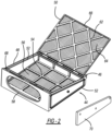
Fig. 2 is a front perspective view of an exemplary lint catcher, -
Fig. 3 is a front perspective view of another embodiment of the lint catcher, -
Fig. 4 is a side view of an exemplary lint catcher seal, -
Fig. 5A is a front perspective view of an exemplary lint filter assembly, -
Fig. 5B is a partial, side cross-section view pf the lint filter assembly shown inFig. 5A , -
Fig. 6 is a perspective view of an exemplary mechanical latch, -
Fig. 7 is a perspective view of an exemplary magnetic latch, -
Fig. 8A is a perspective view of an additional embodiment of the lint catcher, -
Fig. 8B is a side cross-section view of the lint catcher shown inFig. 8A , and -
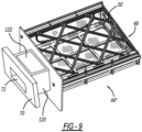
Fig. 9 is a top perspective view of another embodiment of the lint catcher. - Example embodiments will now be described more fully with reference to the accompanying drawings.
- Turning to the figures, a combination washer/dryer is illustrated and designated with the
reference numeral 10. The combination washer/dryer 10 includes acabinet 12 with a plurality of panels 14. Thecontroller panel 20 is illustrated onfront panel 16 of thecabinet 12. The combination washer/dryer 10 includes atub 30 and adrum 32 that is rotatably positioned inside of thetub 30. Awashing circuit 34 is coupled with thetub 30. Additionally, a dryingcircuit 36 is illustrated coupled with thetub 30. Thus, heated air is moved into thedrum 32 and exits through the desiredduct work 38 to ambient. - A
lint filter assembly 40 is positioned into theheating duct work 38. Thelint filter assembly 40 includes ahousing 42 that is positioned into and coupled with theduct work 38. Thehousing 42 receives alint catcher 44. Thelint catcher 44 includes aframe 46 that has a two-piece design with abowl 48 and a lid orcover 50. As illustrated, thelint catcher 44 has an overall rectangular trapezoidal design for sliding into thehousing 42. Thebowl 48 includeswall 52 that surrounds alattice work 54 that includes ascreen 56. Thewall 52 includes anopening 58 that abuts a portion of theduct work 38 so that thehousing 42 receives heated air from thetub 30. The heated air enters into thelint catcher 44, where the lint is retained in thelint catcher 44, then exits through thehousing 42 to ambient. - The
lid 50 includeslattice work 62 and ascreen 64. Thelid 50 is hinged to thebowl 48 to enable thelid 50 to be moved away from thebowl 48 to enable access into thelint catcher 44 to remove the lint. Thus, the lint can be removed from thebowl 48 andlid 50. - The
bowl 48 andlid 50 are manufactured from a plastic material. Preferably, ametallic strip 66 is co-molded into thelid 50.Magnets 68 are likewise co-molded into thewall 52 to enable a magnetic closure between thelid 50 and thebowl 48. Thus, this retains thelid 50 onto thebowl 48 when it is positioned inside of thehousing 42. Additionally, themagnets 68 andmetallic strips 66 could be positioned into other elements of thelint catcher 44. - A
cover 70 is positioned onto a front portion of thewall 52 of thelint catcher 44. Thecover 70 is accessible from outside of thecabinet 12. This enables thelint catcher 44 to be withdrawn from thehousing 42. As shown inFigs. 5A and9 , thecover 70 may include ahandle 72 or opening that enables the user to grasp thecover 70 and remove thelint catcher 44 from thehousing 42. - With reference to
Figs. 3 and 4 , thecover 70 is illustrated with aseal 80. Theseal 80 includes anattachment portion 82, abulb portion 84 and apocket 86 to retain amagnetic strip 88. Theattachment portion 82 is secured into thecover 70 via a channel in thecover 70. Thebulb portion 84 permits movement of thecover 70 when the portion of theseal 80 with themagnetic strip 88 contacts thecabinet 12. Thebulb portion 84 could have a different cross-section depending upon the desired fit of theseal 80 on thecover 70. Themagnetic strip 88 provides a positive retention or locking force that holds/retains thelint catcher 44 in thecabinet 12. - In
Figs. 5A-5B andFigs. 6-7 , twodifferent retention mechanisms lint catcher 44 within thehousing 42. Theretention mechanisms - As illustrated in
Fig. 6 , theretention mechanism 90 is a mechanical latching device with abase 92, that attaches to thehousing 42. Theretention mechanism 90 includesfingers 94 that receive aball 96, which is attached to thecover 70 of thelint catcher 44. As theball 96 is pushed into thefingers 94, thefingers 94 retract into thebase 92. Thefingers 94 are held in the base 92 with theball 96. Thus, thelint catcher 44 is retained or locked with thehousing 42. - An additional push on the
cover 70, in turn, pushes theball 96 further into thebase 92. This releases thefingers 94 which, in turn, releases theball 96 from thefingers 94. Thus, this enables thelint catcher 44 to be withdrawn from thecabinet 12. - As illustrated in
Fig. 7 , theretention mechanism 90 is a magnetic push/push device that has a base 102 with amovable shaft 104. Ametallic striker plate 106 is positioned on thelint catcher 44. As thelint catcher 44 is pushed into thehousing 42, theshaft 104 retracts into thebase 102, which is mounted on thehousing 42. The base also has amagnet 108 that contacts thestriker plate 106 on thecover 70 as thecover 70 is pushed in and the magnetic attractive force between themagnet 108 and thestriker plate 106 retain thelint catcher 44 in thehousing 42. An additional push on thecover plate 70 pushes theshaft 104 further into thedevice 100, which releases themagnet 108 to enable thelint catcher 44 to be withdrawn from thehousing 42 andcabinet 12. -
Figs. 8A and 8B illustrate another lint catcher 44'. The lint catcher 44' shown inFigs. 8A and 8B is substantially the same as that illustrated inFig. 2 except for the addition of one ormore lint peelers 110. Thelint peelers 110 are positioned adjacent the area where thelid 50 attaches to thebowl 48. Thelint peelers 110 may have an overall rectangular configuration and be ring shaped or solid. As illustrated inFig. 8B , thelint peelers 110 move underneath thelint 112 to lift the lint from thebowl 48,lattice work 54 andscreen 56 as thelid 50 is opened. Thus, thelint 112 is scraped from thelattice work 54 andscreen 56 to provide a lifted leading edge to enable removal of thelint 112 from thebowl 48. - Turning to
Fig. 9 , anotherlint catcher 44" is illustrated. Here, astorage bin 120 is positioned on thecover 70 opposite theframe 46. Thestorage bin 120 enables detergent pods, dryer sheets, brushes or the like to be stored within the combination washer/dryer 10 in thestorage bin 120. Upon removal of thelint catcher 44", thestorage bin 120 would be accessible. Thus, a user would have access to the items in thestorage bin 120. Thestorage bin 120 can have a box-like configuration with acover 122 to enable access into thestorage bin 120. - The foregoing description of the embodiments has been provided for purposes of illustration and description. It is not intended to be exhaustive or to limit the disclosure. Individual elements or features of a particular embodiment are generally not limited to that particular embodiment, but, where applicable, are interchangeable and can be used in a selected embodiment, even if not specifically shown or described. The same may also be varied in many ways. Such variations are not to be regarded as a departure from the disclosure, and all such modifications are intended to be included within the scope of the disclosure.
Claims (15)
- A combination washer/dryer (10), comprising:a cabinet (12);a tub (30) positioned inside the cabinet (12);a rotatable drum (32) positioned inside the tub (30);a washing circuit (34) coupled with the tub (30);a drying circuit (36) coupled with the tub (30) for moving heated air into the drum (32), the drying circuit (36) including duct work (38) that directs the heated air through the cabinet (12);a lint filter assembly (40) including a housing (42) that is coupled with the duct work (38) and receives a lint catcher (44) for collecting lint as it moves through the duct work (38); anda retention mechanism (90, 100) that is coupled with the lint filter assembly (40) such that a user pushes the lint catcher (44) into the housing (42) for retaining the lint catcher (44) in a first position where the lint catcher (44) is positively locked in place by the retention mechanism (90, 100) and the user pushes the lint catcher (44) further into the housing (42) to a second position for releasing the retention mechanism (90, 100) so that the lint catcher (44) can be removed from the lint filter assembly (40).
- The combination washer/dryer (10) of Claim 1, wherein the retention mechanism (90, 100) is a push/push mechanism (90, 100) including a mechanism grab latch device (90) or a magnetic device (100).
- The combination washer/dryer (10) of Claims 1 or 2, wherein the retention mechanism (90) is a magnetic strip (88) positioned on the lint filter assembly (40) for magnetically locking the lint catcher (44) in the first position.
- The combination washer/dryer (10) of Claim 3, wherein the lint catcher (44) includes a cover (70) with a seal (80), the seal (80) includes a pocket (86) that retains the magnetic strip (88) , and the magnetic strip (88) provides a positive retention force that retains the lint catcher (44) in the cabinet (12).
- The combination washer/dryer (10) of Claim 4, wherein the seal (80) further includes an attachment portion (82) that is secured in a channel in the cover (70) and a bulb portion (84) that permits movement of the cover (70) when the lint catcher (44) is in the first position.
- The combination washer/dryer (10) of Claims 1 or 2, wherein the retention mechanism (100) includes a magnet (108) that is positioned to contact and be magnetically attracted to a striker plate (106) on the cover (70) to lock the lint catcher (44) in the first position.
- The combination washer/dryer (10) of Claim 6, wherein the retention mechanism (100) further includes a base (102) with a movable shaft (104).
- The combination washer/dryer (10) of Claims 1 or 2, wherein the retention mechanism (90) includes fingers (94) that receive a ball (96) that is attached to the cover (70) to lock the lint catcher (44) in the first position.
- The combination washer/dryer (10) of Claim 8, wherein the retention mechanism (90) includes a base (92) and the fingers (94) are configured to retract into and be held by the base (92) when the ball (96) is pushed into the fingers (94) in the first position.
- The combination washer/dryer (10) of Claim 9, wherein the retention mechanism (90) is configured such that an additional push on the cover (70) pushes the ball (96) further into the base (92) to release the ball (96) from the fingers (94) in the second position, enabling the lint catcher (44) to be withdrawn from the cabinet (12).
- The combination washer/dryer (10) according to any of the preceding Claims, wherein the lint catcher (44) includes a frame (46) with a screen (56) for catching the lint and wherein the frame (46) is two pieces with a bowl (48) and a lid (50).
- The combination washer/dryer (10) of Claim 11, wherein the bowl (48) and the lid (50) are co-molded and wherein one of the bowl (48) and the lid (50) includes a metal piece and the other includes a magnet (68).
- The combination washer/dryer (10) of Claim 11, wherein the lid (50) includes a lint peeler (110) that is configured to move underneath lint in the bowl (48) and lift the lint from the bowl (48) as the lid (50) is opened.
- The combination washer/dryer (10) of Claim 11, wherein the frame (46) includes a storage bin (120).
- The combination washer/dryer (10) of Claim 1, wherein the lint catcher (44) has a rectangular trapezoidal shape.
Applications Claiming Priority (1)
| Application Number | Priority Date | Filing Date | Title |
|---|---|---|---|
| US17/563,606 US20230203745A1 (en) | 2021-12-28 | 2021-12-28 | Customer Accessible Lint Filter |
Publications (1)
| Publication Number | Publication Date |
|---|---|
| EP4206375A1 true EP4206375A1 (en) | 2023-07-05 |
Family
ID=84034117
Family Applications (1)
| Application Number | Title | Priority Date | Filing Date |
|---|---|---|---|
| EP22203978.6A Withdrawn EP4206375A1 (en) | 2021-12-28 | 2022-10-26 | Customer accessible lint filter |
Country Status (2)
| Country | Link |
|---|---|
| US (1) | US20230203745A1 (en) |
| EP (1) | EP4206375A1 (en) |
Families Citing this family (3)
| Publication number | Priority date | Publication date | Assignee | Title |
|---|---|---|---|---|
| US9593441B2 (en) * | 2014-02-28 | 2017-03-14 | ADR Products, LLC | Lint catching system and exhaust assembly |
| US11944254B2 (en) * | 2020-12-07 | 2024-04-02 | Haier Us Appliance Solutions, Inc. | Household appliances and drying systems therefor |
| CN117403428A (en) * | 2023-11-15 | 2024-01-16 | 沪东中华造船(集团)有限公司 | A kind of exhaust filter device for marine dryer |
Citations (4)
| Publication number | Priority date | Publication date | Assignee | Title |
|---|---|---|---|---|
| JP2008079855A (en) * | 2006-09-27 | 2008-04-10 | Matsushita Electric Ind Co Ltd | Drum type washer / dryer |
| KR20100094372A (en) * | 2009-02-17 | 2010-08-26 | 가부시끼가이샤 도시바 | Washing and drying machine |
| JP2013085873A (en) * | 2011-10-21 | 2013-05-13 | Hitachi Appliances Inc | Drum-type washing and drying machine |
| CN109898309A (en) * | 2017-12-08 | 2019-06-18 | 青岛海尔滚筒洗衣机有限公司 | A kind of dryer |
Family Cites Families (3)
| Publication number | Priority date | Publication date | Assignee | Title |
|---|---|---|---|---|
| US3789514A (en) * | 1972-07-24 | 1974-02-05 | Maytag Co | Bulkhead filter assembly |
| DE19613298C1 (en) * | 1996-04-03 | 1997-07-24 | Bauknecht Hausgeraete | Filter for domestic clothes dryer |
| US10280552B2 (en) * | 2016-08-01 | 2019-05-07 | Haier Us Appliance Solutions, Inc. | Filter assembly for a dryer appliance |
-
2021
- 2021-12-28 US US17/563,606 patent/US20230203745A1/en active Pending
-
2022
- 2022-10-26 EP EP22203978.6A patent/EP4206375A1/en not_active Withdrawn
Patent Citations (4)
| Publication number | Priority date | Publication date | Assignee | Title |
|---|---|---|---|---|
| JP2008079855A (en) * | 2006-09-27 | 2008-04-10 | Matsushita Electric Ind Co Ltd | Drum type washer / dryer |
| KR20100094372A (en) * | 2009-02-17 | 2010-08-26 | 가부시끼가이샤 도시바 | Washing and drying machine |
| JP2013085873A (en) * | 2011-10-21 | 2013-05-13 | Hitachi Appliances Inc | Drum-type washing and drying machine |
| CN109898309A (en) * | 2017-12-08 | 2019-06-18 | 青岛海尔滚筒洗衣机有限公司 | A kind of dryer |
Also Published As
| Publication number | Publication date |
|---|---|
| US20230203745A1 (en) | 2023-06-29 |
Similar Documents
| Publication | Publication Date | Title |
|---|---|---|
| US20230203745A1 (en) | Customer Accessible Lint Filter | |
| EP2376702B1 (en) | Dryer and foreign material removing apparatus thereof | |
| EP2788539B1 (en) | Filter guide having latch device of filter cover and clothes-drying machine using the same | |
| RU2629088C2 (en) | Linen processing device | |
| US2786730A (en) | Cabinet equipment | |
| CN100591833C (en) | Front load washing machine with door that opens upwards | |
| EP2251477A1 (en) | Washing machine | |
| KR102364520B1 (en) | Steam iron with collection compartment for travertine deposits | |
| CN112006625A (en) | Semi-automatic door opening and closing device of dish washing machine and quick drying control method of dish washing machine | |
| EP2843123A1 (en) | Laundry machine with de-fluff filter | |
| RU2617977C2 (en) | Laundry processing device | |
| CN110512960A (en) | A kind of electric appliance door lock | |
| GB2081858A (en) | Domestic appliance | |
| CN208038817U (en) | Wash shield equipment | |
| US11390980B2 (en) | Drawer for laundry appliance | |
| CA1229738A (en) | Sliding access door for washing machine | |
| RU2423564C2 (en) | Facility for access to drain filter of washing machine with upper load | |
| US3244830A (en) | Latching mechanism for front opening cabinets | |
| CN106996002B (en) | Laundry treating machine | |
| JP6667123B2 (en) | Outlet equipment | |
| CN106939502B (en) | Laundry treating machine | |
| CN115928400A (en) | Foreign particle collector for laundry appliance | |
| EP3272932B1 (en) | Laundry treatment device | |
| TW202012736A (en) | Clothes dryer | |
| KR970002541B1 (en) | Door locks in the dishwasher |
Legal Events
| Date | Code | Title | Description |
|---|---|---|---|
| PUAI | Public reference made under article 153(3) epc to a published international application that has entered the european phase |
Free format text: ORIGINAL CODE: 0009012 |
|
| STAA | Information on the status of an ep patent application or granted ep patent |
Free format text: STATUS: THE APPLICATION HAS BEEN PUBLISHED |
|
| AK | Designated contracting states |
Kind code of ref document: A1 Designated state(s): AL AT BE BG CH CY CZ DE DK EE ES FI FR GB GR HR HU IE IS IT LI LT LU LV MC ME MK MT NL NO PL PT RO RS SE SI SK SM TR |
|
| STAA | Information on the status of an ep patent application or granted ep patent |
Free format text: STATUS: THE APPLICATION IS DEEMED TO BE WITHDRAWN |
|
| 18D | Application deemed to be withdrawn |
Effective date: 20240106 |