EP2843123A1 - Laundry machine with de-fluff filter - Google Patents
Laundry machine with de-fluff filter Download PDFInfo
- Publication number
- EP2843123A1 EP2843123A1 EP13182328.8A EP13182328A EP2843123A1 EP 2843123 A1 EP2843123 A1 EP 2843123A1 EP 13182328 A EP13182328 A EP 13182328A EP 2843123 A1 EP2843123 A1 EP 2843123A1
- Authority
- EP
- European Patent Office
- Prior art keywords
- filter
- fluff
- laundry machine
- fluff filter
- sidewall
- Prior art date
- Legal status (The legal status is an assumption and is not a legal conclusion. Google has not performed a legal analysis and makes no representation as to the accuracy of the status listed.)
- Granted
Links
- 238000001035 drying Methods 0.000 claims abstract description 81
- 238000001914 filtration Methods 0.000 claims abstract description 31
- 239000012530 fluid Substances 0.000 claims abstract description 8
- 239000002245 particle Substances 0.000 claims abstract description 8
- 238000004891 communication Methods 0.000 claims abstract description 7
- 238000005406 washing Methods 0.000 claims description 9
- 238000000926 separation method Methods 0.000 claims description 4
- 238000003825 pressing Methods 0.000 claims description 3
- 238000010438 heat treatment Methods 0.000 description 9
- 238000003780 insertion Methods 0.000 description 8
- 230000037431 insertion Effects 0.000 description 8
- 239000000463 material Substances 0.000 description 7
- 238000007789 sealing Methods 0.000 description 6
- 230000002093 peripheral effect Effects 0.000 description 5
- 229920000642 polymer Polymers 0.000 description 5
- 238000004140 cleaning Methods 0.000 description 4
- 230000035508 accumulation Effects 0.000 description 3
- 238000009825 accumulation Methods 0.000 description 3
- 230000000903 blocking effect Effects 0.000 description 3
- 230000008878 coupling Effects 0.000 description 3
- 238000010168 coupling process Methods 0.000 description 3
- 238000005859 coupling reaction Methods 0.000 description 3
- 238000007689 inspection Methods 0.000 description 3
- 239000004695 Polyether sulfone Substances 0.000 description 2
- 239000004743 Polypropylene Substances 0.000 description 2
- 230000009471 action Effects 0.000 description 2
- 238000004026 adhesive bonding Methods 0.000 description 2
- 230000002708 enhancing effect Effects 0.000 description 2
- 230000007257 malfunction Effects 0.000 description 2
- 238000000034 method Methods 0.000 description 2
- 229920006393 polyether sulfone Polymers 0.000 description 2
- 238000005381 potential energy Methods 0.000 description 2
- 230000009467 reduction Effects 0.000 description 2
- 239000000243 solution Substances 0.000 description 2
- XLYOFNOQVPJJNP-UHFFFAOYSA-N water Substances O XLYOFNOQVPJJNP-UHFFFAOYSA-N 0.000 description 2
- -1 Polypropylene Polymers 0.000 description 1
- 239000004676 acrylonitrile butadiene styrene Substances 0.000 description 1
- 238000005452 bending Methods 0.000 description 1
- 238000007664 blowing Methods 0.000 description 1
- 230000006835 compression Effects 0.000 description 1
- 238000007906 compression Methods 0.000 description 1
- 238000001816 cooling Methods 0.000 description 1
- 230000001419 dependent effect Effects 0.000 description 1
- 239000003599 detergent Substances 0.000 description 1
- 230000001627 detrimental effect Effects 0.000 description 1
- 238000009826 distribution Methods 0.000 description 1
- 238000005516 engineering process Methods 0.000 description 1
- 238000000605 extraction Methods 0.000 description 1
- 238000002347 injection Methods 0.000 description 1
- 239000007924 injection Substances 0.000 description 1
- 230000003993 interaction Effects 0.000 description 1
- 238000010412 laundry washing Methods 0.000 description 1
- 238000012423 maintenance Methods 0.000 description 1
- 239000004033 plastic Substances 0.000 description 1
- 229920003023 plastic Polymers 0.000 description 1
- 239000004417 polycarbonate Substances 0.000 description 1
- 229920000515 polycarbonate Polymers 0.000 description 1
- 229920001155 polypropylene Polymers 0.000 description 1
- 230000008569 process Effects 0.000 description 1
- 230000003014 reinforcing effect Effects 0.000 description 1
Images


Classifications
-
- D—TEXTILES; PAPER
- D06—TREATMENT OF TEXTILES OR THE LIKE; LAUNDERING; FLEXIBLE MATERIALS NOT OTHERWISE PROVIDED FOR
- D06F—LAUNDERING, DRYING, IRONING, PRESSING OR FOLDING TEXTILE ARTICLES
- D06F58/00—Domestic laundry dryers
- D06F58/20—General details of domestic laundry dryers
- D06F58/22—Lint collecting arrangements
-
- D—TEXTILES; PAPER
- D06—TREATMENT OF TEXTILES OR THE LIKE; LAUNDERING; FLEXIBLE MATERIALS NOT OTHERWISE PROVIDED FOR
- D06F—LAUNDERING, DRYING, IRONING, PRESSING OR FOLDING TEXTILE ARTICLES
- D06F25/00—Washing machines with receptacles, e.g. perforated, having a rotary movement, e.g. oscillatory movement, the receptacle serving both for washing and for centrifugally separating water from the laundry and having further drying means, e.g. using hot air
Landscapes
- Engineering & Computer Science (AREA)
- Textile Engineering (AREA)
- Detail Structures Of Washing Machines And Dryers (AREA)
Abstract
Description
- The present invention relates to laundry treatment appliances or machines. In more detail, the present invention refers to appliances for drying laundry, both for domestic and professional use. More particularly, the present invention relates to a de-fluff filter.
- Drying and washing/drying laundry machines - which will be referred to simply as laundry machine in the following - typically comprise a casing substantially parallepiped-shaped. The casing accommodates a laundry treating chamber, comprising a drum, generally rotatable, apt to contain the laundry to be dried, in the case of a washing/drying laundry machine, the drum is rotatably contained in a tub. A front panel of the casing has a loading opening to access the treating chamber for loading/unloading the laundry, and a door is provided for closing the loading opening, particularly during the laundry machine operation.
- The casing also accommodates the electrical, electronic, mechanical, and hydraulic components necessary for the operation of the laundry machine. Particularly, laundry-drying capable machines features an air circuit (comprising, for example, fans, air ducts, a moisture condensing unit, a heating unit, etc.) adapted to heat air, blow it into the drum where it removes moisture from the laundry, suck out from the drum the moisturized air, de-moisturize the air and reiterate such actions thereby performing a laundry drying cycle.
- During a washing and/or drying process, the laundry under treatment typically loses lint particles or fluff. The fluff is generally light and tiny, thus it can be brought out from the drum by the hot drying air flowing therein and then into the air circuit.
- Once in the air circuit, the fluff is likely to accumulate therein, thereby possibly obstructing air ducts of the air circuit or negatively affecting the operation of one or more of its components (e.g., fluff may deposit on a fan, to the extent of possibly causing the latter to operate with a lower efficiency or completely stop it). In general, fluff accumulation has a detrimental effect on the laundry drying machine operation.
- Therefore de-fluff filters have been designed for the purpose of retaining the fluff so as to prevent it from damaging the laundry machine components. Nevertheless, the de-fluff filter needs to be periodically cleaned to avoid it to get clogged, event that may reduce the laundry machine efficiency or even cause a laundry drying machine malfunction, at least of the air circuit thereof. To this purpose, the de-fluff filter is usually removably accommodated in a filter seat within the air circuit, for example in a position located at the front of the casing in a top portion thereof, i.e. in position that are easily reachable by a user. Such de-fluff filter positions complicate the arrangement of the drying air circuit path causing the drying air flow to lose a great amount of its energy and hence reducing the drying performance of the appliance.
- An example of such de-fluff filter is provided by the UK Patent No.
GB1554725 GB1554725 - The Applicant has tackled the problem of devising a laundry machine comprising a de-fluff filter arrangement with an improved structure and a corresponding positioning thereof within the air circuit of the laundry machine adapted to improve the efficiency of the drying process.
- The Applicant has devised a de-fluff filter that is easy to insert into, and to remove out of a corresponding housing, and homogenously distributes the drying air flow.
- One aspect of the present invention proposes a laundry machine adapted to dry laundry by means of a flow of drying air. The laundry machine comprises a casing for accommodating components necessary for the operation of the laundry machine. Inside the casing, a laundry treating chamber adapted to contain the laundry to be dried is provided and a casing top element incorporates at least part of an air circuit in fluid communication with the laundry treating chamber through an inlet opening and through an outlet opening, and defining an air-path for the flow of drying air between said inlet and outlet openings. Said casing top element comprises a filter housing for removably accommodating a de-fluff filter, said filter housing being provided in the air-path and being accessible through a housing aperture provided on the casing top element, a de-fluff filter for trapping fluff and/or lint particles carried by the flow of drying air crossing said de-fluff filter, the de-fluff filter comprising a filtering element and a hollow chamber accessible through an inlet aperture and through an outlet portion. In the solution according to an embodiment of the present invention, the de-fluff filter further comprises at least one air guiding element having a shape that distributes homogenously the flow of drying air inside the hollow chamber and along the outlet portion of the de-fluff filter.
- Preferred features of the present invention are set in the dependent claims.
- In an embodiment of the invention, the de-fluff filter comprises a filter box having a bottom wall a rear sidewall, a front sidewall, a first transversal sidewall, and a second transversal sidewall, said sidewalls delimiting a top aperture which is closable by a cover element movably coupled to the filter box.
- In an embodiment of the invention, the second transversal sidewall comprises the outlet portion, said outlet portion comprising a frame that encloses a plurality of windows separated from each other by separation elements, the separation elements extending from a lower portion of the frame at the bottom wall of the filter box up to a higher portion of the frame at the top aperture, the filtering element being coupled to the outlet portion superimposed to the plurality of windows.
- In an embodiment of the invention, the filter housing comprises an opened side having a frame defining a plurality of side windows separated one another by further separating elements, each one of said plurality of side windows being adapted to be aligned with a corresponding window of the plurality of windows of the outlet portion of the de-fluff filter when the latter is inserted in the filter housing.
- In an embodiment of the invention, the at least one air guiding element comprises an air guiding wall provided in the filter box and extending between a portion of the first transversal sidewall close to the rear wall and an end of the second transversal sidewall adjacent to the front sidewall.
- In an embodiment of the invention, the at least one air guiding element further comprises one or more air guiding blades provided on the cover element of the de-fluff filter, the air guiding blades being designed in such a way to reach the bottom wall of the filter box, when the cover element is in the closed position.
- In an embodiment of the invention, a plurality of air guiding elements are provided, which subdivide the filter box in sub-chambers having a sectional area that increases along the drying air flow direction path.
- In an embodiment of the invention, the inlet aperture is provided in the rear sidewall of the filter box, and wherein the de-fluff filter further comprises a closing element hinged to the first transversal sidewall and to the second transversal sidewall close to the rear sidewall for closing the inlet aperture by abutting an abutment element provided at the inlet aperture, and adapted to be pivoted towards the top aperture by the flow of drying air.
- In an embodiment of the invention, the laundry machine further comprises an adapter element adapted to fluidly connect the inlet opening with the de-fluff filter via the inlet aperture, and wherein the de-fluff filter further comprises a protruding frame that surrounds the inlet aperture the protruding frame being adapted to engage with a gasket element provided around an aperture of the adapter element.
- In an embodiment of the invention, the de-fluff filter further comprises an ejection device adapted to eject the de-fluff filter by pressing a pushbutton portion.
- In an embodiment of the invention, the de-fluff filter further comprises a cover support coupled with the front sidewall adapted to protrude outwards the aperture when the de-fluff filter is inserted in the filter housing, the cover support being adapted to engage with an aesthetic cover.
- In an embodiment of the invention, the casing top element comprises a moisture condensing element.
- In an embodiment of the invention, the casing top element comprises a heat pump apparatus.
- In an embodiment of the invention, the laundry machine is a washing/drying laundry machine.
- In an embodiment of the invention, the de-fluff filter is vertically superposed to a washing treatment products dispensing arrangement.
- These, and others, features and advantages of the solution according to the present invention will be better understood with reference to the following detailed description of some embodiments thereof, provided for illustrative and not restrictive purposes, to be read in conjunction with the attached drawings. In this regard, it is expressly intended that the drawings are not necessarily to scale and that, unless specified otherwise, they simply aim to conceptually illustrate the structures and procedures. In particular:
-
Figure 1 is a perspective view of a laundry machine according to an embodiment of the present invention; -
Figure 2A is a perspective view of the laundry machine ofFigure 1 , showing a top thereof in exploded view; -
Figure 2B is a perspective view of a base element of the top of the laundry machine according to an embodiment of the present invention; -
Figure 3A is a perspective exploded view of a de-fluff filter according to an embodiment of the present invention; -
Figure 3B is a cross-sectional perspective view on IIIB-IIIB axis of a de-fluff filter according to an embodiment of the present invention comprising an enlarged view of a portion of a transversal sidewall thereof; -
Figure 3C is a perspective view with removed parts of a de-fluff filter and of an inlet aperture of a de-fluff filter housing according to an embodiment of the present invention; -
Figure 3D and 3E are two cross-sectional side views on IIIDE-IIIDE axis of a rear portion of a de-fluff filter according to an embodiment of the present invention; -
Figure 3F is a perspective view from below of a de-fluff filter according to an embodiment of the present invention; -
Figure 3G and 3H show two perspective views of the de-fluff filter showing a lid thereof in a closed and in an opened position, respectively, with enlarged views highlighting features of the lid; -
Figure 4A is a plan view of a top base element with a de-fluff filter inserted according to an embodiment of the present invention, featuring portions in transparency for highlighting mechanical interaction between the two; -
Figure 4B is an plan view of the top base element ofFigure 4A with the de-fluff filter in a released condition; -
Figure 5A is a perspective view of an auxiliary de-fluff filter according to an embodiment of the present invention; -
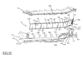
Figure 5B is a cross-sectional view of a portion of an air circuit of a laundry machine along a V-V axis in which housing grooves accommodate the auxiliary de-fluff filter ofFigure 5A , and -
Figure 5C is a cutaway and exploded view of a portion of the air circuit comprising the housing grooves and of the auxiliary de-fluff filter. - With reference to the drawings,
Figure 1 is a perspective view of a laundry machine, globally denoted as 100, according to an embodiment of the present invention. - The
laundry machine 100 comprises alaundry treatment chamber 105 for accommodating the items to be dried or washed and dried, such as clothes, garments, linen, and similar laundry items. Preferably, thelaundry treatment chamber 105 includes a drum (not shown) rotatably mounted inside a machine cabinet orcasing 110, and in case thelaundry machine 100 is a washing/drying laundry machine the drum is arranged within a tub (not shown) housed in the machine casing orcabinet 110. - The
casing 110 generally accommodates all the electrical, electronic, mechanical, and hydraulic components necessary for the operation of the laundry machine. Thecasing 110 has generically a parallelepiped shape, with afront wall 115, two side walls 120 (only one visible inFigure 1 ), a rear wall (not visible), a basement and a top element, or simply top 125. Thefront wall 115 is provided with an opening for accessing the drum and with an associateddoor 117 for closing the opening. In the upper part of thefront wall 115, amachine control panel 130 is located, and, aside thecontrol panel 130, adrawer 135 is provided, which is part of a washing treatment products dispensing arrangement, for loading laundry washing treatment products like detergents and softeners. The top 125 closes thecasing 110 from above, and defines a worktop. - In one embodiment of the invention, a de-fluff filter (aesthetic)
cover 140 is exposed on thecontrol panel 130 on thefront wall 115, e.g. above thedrawer 135, and flush therewith. Preferably, thede-fluff filter cover 140 may comprise a pushbutton portion 145 (which purpose will be described in the following). - Reference is now made to
Figures 2A-2B , which are a perspective view of thelaundry machine 100 with its top 125 in exploded view and a perspective view of abase element 205 of the top 125 with some parts removed. - In one embodiment of the invention, the top 125 integrates part of an air circuit adapted to circulate drying air across the
laundry treating chamber 105 for drying the laundry stored therein (as described in greater detail below). - The top 125 comprises the
base element 205, which has aninlet opening 210 and anoutlet opening 215, theinlet opening 210 being in fluid communication with thelaundry treatment chamber 105 through a chamber outlet, theoutlet opening 215 being in fluid communication with afan arrangement 216. - The
fan arrangement 216 comprises a fan and a corresponding fan duct, the fan produces the drying air flow inside the air circuit by sucking drying air from theoutlet opening 215 and blowing the drying air into thelaundry treatment chamber 105, theoutlet opening 215 and thelaundry treatment chamber 105 being both fluidly connected to thefan arrangement 216. - In the region of the
base element 205, preferably near the front-left corner thereof, afilter housing 217 is provided suitable to house a de-fluff filter 218 (described in greater detail below). Preferably, thefilter housing 217 has roughly a right trapezoid outline in plan view (e.g., similar to a grand piano), with ashorter sidewall 217a (corresponding to a lesser base of the right trapezoid) in fluid communication with the chamber outlet by means of theinlet opening 210, and alarger sidewall 217b (opposite to theshorter sidewall 217a, and corresponding to a greater base of the right trapezoid) that has ahousing aperture 219 opened on themachine front wall 115 preferably in aseparating wall 205a (visible inFigure 5C ) of thebase element 205, preferably in a portion adjacent to thecontrol panel 130, even more preferably above thedrawer 135 for allowing the insertion of thede-fluff filter 218. Moreover, thefilter housing 217 comprises aright sidewall 217c substantially corresponding to a portion of a lateral sidewall of thebase element 205 of the top 125 (and corresponding to the right leg of the right trapezoid) and a transversal openedside 217d, preferably inclined (opposite to theright sidewall 217c and corresponding to the inclined leg of the right trapezoid). - In one embodiment of the present invention, the
inlet opening 210 is fluidly connected to anadapter element 212, which is provided to fluidly connect the inlet opening 210 with thefilter housing 217 and the de-fluff filter 218 (when inserted in the filter housing 217). Preferably, but not limitatively, theadapter element 212 may be a parallelepiped-shape element adapted to be coupled to thebase element 205, with conical or cylindrical passage(s) provided therein with two opposite apertures to fluidly connect the inlet opening 210 with thede-fluff filter 218. Theadapter element 212 may be made of any suitable material, e.g. a polymeric material, and is coupled to thebase element 205 by means of any suitable coupling arrangement, e.g. by tightly fitting a rear portion of the filter housing 217 (adjacent to theshorter sidewall 217a). - In a preferred embodiment of the invention, the aperture facing the
filter housing 217 of theadapter element 212 is surrounded by agasket element 212a which protrudes towards the inside of thefilter housing 217. In alternative embodiments of the present invention in which theadapter element 212 is not provided, an alternative gasket element may be directly provided around theinlet opening 210. - In one embodiment of the present invention, the transversal opened
side 217d comprises aframe 220 that defines a plurality ofside windows 220a separated one from the other by separating elements, such as forexample mullion elements 220b, preferably prism-shaped. Preferably, at theframe 220 housing grooves (not shown inFigures 2A and2B , but visible inFigure 5B where are denoted with thereferences 505u and 505l) adapted to house an auxiliary filter 221 (described in detail in the following) are provided. Advantageously, a plurality offlap elements 222 may be provided. Theflap elements 222 protrude from theframe 220 opposite to thefilter housing 217 in order to direct the drying air flow exiting the transversal openedside 217d towards the rest of the air circuit defined in the top 125. - In the central region of the
base element 205, there is accommodated a first heat-exchanging unit, such as amoisture condensing element 225, for example comprising an evaporator of a heat pump apparatus. Themoisture condensing element 225 is adjacent to the transversal openedside 217d, and thus the external surface of the former is in fluid communication with the latter. Next to themoisture condensing element 225, opposite to thefilter housing 217, there is provided a second heat-exchanging unit, such as a dryingair heating element 230, for example comprising a condenser of the heat pump apparatus. Themoisture condensing element 225 has the function of dehydrating the drying air, by cooling it down; the dryingair heating element 230 has instead the function of heating the dehydrated drying air. A compressor (not shown) for the heat pump may be attached to thebase element 205 in correspondence of the front-right corner thereof, the body of the compressor protruding from below thebase element 205. In an alternative embodiment, the compressor may be located in the bottom of thecasing 110, attached to the basement of thelaundry machine 100, and be fluidly connected to themoisture condensing element 225 accommodated in the top 125 by means of flexible pipes that preferably run along a rear corner of thecasing 110 or along thelaundry treatment chamber 105 of thelaundry machine 100. In a different embodiment of the present invention, thelaundry machine 100 may comprise an air-air or an air-water heat exchanger apparatus and an electric heater instead of the heat pump apparatus. - The
base element 205 of the top 125 is covered by aninner panel 235, that covers essentially themoisture condensing element 225, the dryingair heating element 230 and thede-fluff filter 218. The top 125 is completed by an outer (aesthetic)panel 240. Thebase element 205 and theinner panel 235 define an air-path that conveys the moisture-laden air coming from the laundry treatment chamber 105 (through the inlet opening 210) towards thede-fluff filter 218, preventing the moisture-laden air from entering directly themoisture condensing element 225 or the drying air heating element 230 (i.e., before being filtered by the de-fluff filter 217), and then the drying air flow follows the air-path from thede-fluff filter 218 to theheating element 230, passing through themoisture condensing element 225, and eventually reaching theoutlet opening 215. - Preferably, the top 125, once assembled, forms a unit that is ready to be mounted to the
casing 110, simply by placing it in the correct alignment, so that theopenings fan arrangement 216, respectively, thus realizing a closed air circuit comprising thelaundry treatment chamber 105 and the air-path defined by thebase element 205 and theinner panel 235, and thefan arrangement 216. The top 125 may then be secured to thecasing 110 by conventional means (e.g., by means of gluing, screwing or other connecting means). - In the
laundry machine 100, when operated in dryer mode (i.e., for drying items stored in the drum), drying air (i.e., warm and dry air) is typically caused to flow through thedrum 105 inside thelaundry treating chamber 105, where the items to be dried are contained. The drying air binds to moisture particles from the laundry and/or dispersed within thelaundry treating chamber 105 and carries them away. The drying air may also carry away fluff (e.g., generated from the laundry during laundry treating processes) from the laundry together with moisture particles. After exiting the drum through the chamber outlet, the flow of now moisture-laden drying air passes through thede-fluff filter 218 where substantially any fluff carried by the drying air flow together with moisture particles is caught and remains trapped. Instead, the moisture-laden drying air is conveyed towards themoisture condensing element 225, where the moisture-laden drying air is at least partially dried, i.e. dehydrated, and such dehydrated drying air flow is then heated by theair heating element 230 through which the drying air flows, which heats the drying air up to a drying temperature (e.g., set by a user through thecontrol panel 130 via the selection of a drying program). Then the drying air is sucked by the fan through the fan intake and is caused to pass again through thedrum 105 drying the laundry therein stored and then repeating the cycle just described. - Considering now
Figures 3A-3H , they are different views of thede-fluff filter 218 according to embodiments of the present invention. - The
de-fluff filter 218 is designed to be inserted inside thefilter housing 217 preferably through thehousing aperture 219 exposed on thefront wall 115. Preferably, thede-fluff filter 218 is designed such as an extractable drawer. - The
de-fluff filter 218 comprises afilter box 303, a cover element, such as for example alid 306, and in addition it may preferably comprise a closing element, such a swingingbulkhead 309, anejection device 312, and alocking element 315. - The
filter box 303 has a parallelepiped shape, preferably with a roughly rectangular trapezoid base. For example, thefilter box 303 of thefilter housing 217 may have a shape similar to that of a grand piano, with arear sidewall 303a, afront sidewall 303b, a firsttransversal sidewall 303c, a secondtransversal sidewall 303d, preferably curved, and abottom wall 303e. The sidewalls 303a, 303b, 303c, 303d delimit atop aperture 303t of thefilter box 303. Thefilter box 303 may be made in any suitable material, such as for example a suitable polymer (e.g., Polypropylene PP). - Preferably (as can be appreciated in
Figure 2B ), thefilter box 303 is designed in such a way that, once thede-fluff filter 218 is inserted into thefilter housing 217, the former substantially tightly fits the latter. Even more preferably, the sidewalls 303a and 303c are adapted to substantially flank the sidewalls 217a and 217c, respectively, of thefilter housing 217 and may contact them, while thefront sidewall 303b substantially closes thehousing aperture 219 and the secondtransversal sidewall 303d faces the transversal openedside 217d of thefilter housing 217, preferably remaining separated therefrom. - Preferably, the
filter box 303 is designed in such a way that its secondtransversal sidewall 303d remains spaced apart from the transversal openedside 217d of thefilter housing 217, thus defining a gap between the secondtransversal sidewall 303d and the transversal openedside 217d. - The second
transversal sidewall 303d operates substantially as a filtering portion and as an outlet portion of thede-fluff filter 218. The secondtransversal sidewall 303d comprises aframe 318 that encloses a plurality ofwindows 318a separated from each other by separating elements, such as for examplebox mullion elements 318b, preferably parallelepiped shaped. Thebox mullion elements 318b extend from a lower portion of the frame 318 (at thebottom wall 303b) of thefilter box 303 up to a higher portion of the frame 318 (at thetop aperture 303t). Advantageously, thebox mullion elements 318b are designed to align with themullion elements 220b of the transversal openedside 217d (once the de-fluff filter 305 is inserted into the filter housing 217), in such a way to not to hinder the drying air flow. - The
filter box 303 further comprises a filtering element, such as for example afiltering mesh 321 preferably rectangular and is sized with a length and a height substantially equal to a length and a height of the secondtransversal sidewall 303d. Thefiltering mesh 321 is coupled to the secondtransversal sidewall 303d covering the apertures of thewindows 318a in such a way to filter the drying air flow passing therethrough (as will be described in greater detail in the following). Thefiltering mesh 321 is preferably coupled to the secondtransversal sidewall 303d on an internal face thereof (i.e., facing the inside of the filter box 303). Thefiltering mesh 321 may be made in any suitable material, such as for example a suitable polymer (e.g., Polyethersulfone or "PES") that may be over-injected onto the internal face of the secondtransversal sidewall 303d. Alternatively, thefiltering mesh 321 may be attached to theframe 318 of the secondtransversal sidewall 303d in any other suitable manner (e.g., by gluing together thefiltering mesh 321 and the secondtransversal sidewall 303d) or, conversely, may be removably coupled with the frame 318 (e.g., by providing suitable snap-fit engage elements). Alternatively, a plurality of smaller filtering meshes may be provided each one adapted to be coupled to arespective window 318a. - It should be noted that the
mullion elements 318b, along enhancing the structural strength of theframe 318 also enhance a robustness of thefiltering mesh 321 preventing deformation of thefiltering mesh 321 that the air flow may provoke, e.g. a bending of the central portion of thefiltering mesh 321 in the direction of the flow of air that could cause a concentration of trapped fluff in such bent central portion. - The
filter box 303 preferably also comprises acover support 324 attached to (or, alternatively, formed integral with) thefront sidewall 303b. Thecover support 324 is designed to protrude outwards from theaperture 219 in thelarger sidewall 217b in order to support the de-fluff filter cover 140 (when thede-fluff filter 218 is inserted into the filter housing 217). Preferably, thecover support 324 comprises atab 327 protruding substantially transversal to thefront sidewall 303b towards therear sidewall 303a on an end of thecover support 324. For example, thede-fluff filter cover 140 may be coupled to thecover support 324 by means of one or more snap-fit elements (not shown), each fitting a corresponding coupling element, such asholes 324a, provided on thecover support element 324. In other embodiments according to the present invention, a tab may be placed in a different position and/or more than just a tab may be provided. - The
cover support 324, thefront sidewall 303b and/or thede-fluff filter cover 140 may be either formed as different elements that can be engaged one another in any suitable known manner, or as a one-piece element. - In alternative embodiments of the present invention, an alternative cover element may be provided featuring a grasping element (such as for example a handle).
- The
rear sidewall 303a of thefilter box 303 comprises aninlet aperture 330 which is adapted to receive the drying air flow coming from thelaundry treatment chamber 105 through the inlet opening 210 in theshorter sidewall 217a. Preferably the outlet portion, i.e. the secondtransversal sidewall 303d, has a greater extension than theinlet aperture 330, such that thefiltering mesh 321 arranged on theoutlet portion 303d may have a wide extension. Preferably, therear sidewall 303a is also provided with a protrudingframe 333 that surrounds theinlet aperture 330 and protrudes from a border of the filter box 303surrounding theinlet aperture 330 towards the outside of thefilter box 303. The protrudingframe 333 is adapted to engage with thegasket element 212a of theadapter element 212 preferably in an airtight manner (thus fluidly connecting thede-fluff filter 218 with inlet opening 210). - Advantageously, the swinging
bulkhead 309 is provided at theinlet aperture 330. The swingingbulkhead 309 has a shape, e.g. substantially rectangular, adapted to close, preferably seal, theinlet aperture 330. The swingingbulkhead 309 is designed to have a weight such that a kinetic force of the drying air flow (schematically represented by an arrow inFigure 3E ) from thelaundry treatment chamber 105 is able to swing the bulkhead towards inside of the filter box 303 (thus, clearing the inlet aperture 330). The swingingbulkhead 309 may be made in any suitable material, e.g. a polymer. - Preferably, the swinging
bulkhead 309 is hinged to the firsttransversal sidewall 303c and to the secondtransversal sidewall 303d close to therear sidewall 303a. For example, the swingingbulkhead 309 may be provided with two protrudingpins 309a on opposite shortest sides (at top corners thereof), which are adapted to be inserted into two matching rear bores 336, a first one provided in the firsttransversal sidewall 303c and a second one provided in the secondtransversal sidewall 303d. Preferably, at theinlet aperture 330 anabutment element 330a is provided that is adapted to prevent the swingingbulkhead 309 from swinging towards the outside of the filter box 303 (i.e., the swingingbulkhead 309 is allowed to swing only towards the inside of the filter box 303). Thanks to the swingingbulkhead 309 and theabutment element 330a it is possible to prevent, or substantially reducing, any spurious flow of air from thede-fluff filter 218 towards the inlet opening 210 (i.e., opposite to the direction desired for the flow of drying air). - Preferably, in the
bottom wall 303e aniche 339 is formed. Theniche 339 extends inwards into thefilter box 303. Theniche 339 comprises aside opening 339a on thetransversal wall 303c and is preferably located close to thefront wall 303b. Inside theniche 339, afirst rail element 339b preferably protrudes from a bottom wall thereof (e.g. in a central position), parallel to thetransversal wall 303c. Moreover, engagement elements, such as snap-fit elements 339c, protrude from sidewalls of theniche 339, preferably with the exception of the sidewall where theside opening 339a is formed. - The
niche 339 is adapted to house theejection device 312 that allows ejecting thede-fluff filter 218 from its housing 217 (as described in the following). Theejection device 312 allows thede-fluff filter 218 to be at least slightly ejected from thefilter housing 217 so as to be easily grasped by a user. - In one embodiment of the present invention, the
ejection device 312 comprises a substantially box-like container 312a, with a major side opened and a (long) lateral side lower than the others. The box-like container 312a houses a pushingelement 342 adapted to engage with a matching engaging element provided in theright sidewall 217c (not shown inFigures 3A-3H , but visible inFigures 4A and4B wherein is denoted with the reference 410) in order to block thede-fluff filter 218 in an operating position (as described in the following). - For example, the pushing
element 342 comprises an engaginghead 345 and a biasing element 348 (such as for example a coil spring), with the engaginghead 345 that has a portion partly protruding outwards the box-like container 312a (through the lowest lateral side mentioned above) and also protruding outwardly from theside opening 339a, once the ejection device is inserted into theniche 339. The engaginghead 345 is coupled to abiasing element 348, for example a coil spring, at one end of the latter, while an opposite end of the biasingelement 348 contacts a (short) lateral side of the box-like container 312a. - Moreover, the
ejection device 312 may comprise asecond rail element 312b (provided in a bottom wall of the box-like container 312a) and engage elements, such as matching snap-fit elements 312c (provided in lateral sides of the box-like container 312a) adapted to match the snap-fit elements 339c, (if) provided in theniche 339. Advantageously, the first andsecond rail elements head 345, which comprisesrail slots 345a adapted to be fitted by therail elements like container 312a of theejection device 312 and by a border of theside opening 339a of theniche 339, in order to guide (longitudinally) the movements of the engaginghead 345 when the latter is biased by the biasingelement 348, or the wholede-fluff filter 217 is moved against such biasing (as will described in the following). - The locking
element 315 is adapted to maintain thede-fluff filter 218 in the operating position once inserted into thefilter housing 217. - For example, the locking
element 315 is substantially an "L"-shaped lever that comprises apush portion 315a and anose portion 315b substantially transversal to the former. Thepush portion 315a is preferably parallelepiped-shaped, while thenose portion 315b is substantially a stick element comprising anose element 351. Thenose element 351 protrudes transversal to thenose portion 315b, and is preferably positioned at a free end of thenose portion 315b opposite to an intersection of the twoportions nose element 351 comprises ablocking element 351a, with preferably, a cylindrical shape with an inclined top surface (inclined with a higher edge facing towards thecover support 324 and a lower edge facing towards thefilter box 303 when the lockingelement 315 is coupled with the cover support 324) and one or more slidingelements 351b such as for example two ribs having a right triangle shape with the right angle thereof adjacent to theblocking element 351a. - At the intersection between the two
portions pins 315c protrude in opposite directions from the lockingelement 315 substantially transversal to both theportions element 315 is preferably hinged to thecover support 324 by means of thepins 315c which are inserted into correspondingpinholes 324b provided in opposite position on thecover support 324. In such a hinged position, thenose element 351 is exposed from anose window 324b provided in a lower portion of thecover support 324. The lockingelement 315 also comprises a biasing element, such as acoil spring 315d, which is coupled to thepush portion 315a (at a rear side thereof) at one of its ends, and contact a recessedwall 324d of thecover support 324 at the opposite end. - In an inner portion of the
filter box 303 a guidingwall 354 may be preferably provided in order to guide the drying air flow from theinlet aperture 330 to the secondtransversal sidewall 303d. For example, the guidingwall 354 may be a curved wall connecting the firsttransversal sidewall 303c with an end of the secondtransversal sidewall 303d adjacent to thefront sidewall 303b. Generally, the guidingwall 354 is designed in such a way to provide the best fluid-dynamic behaviour for the drying air flow inside the de-fluff filter box 218 (e.g., adapted to effectively direct the drying air flow homogenously towards the whole secondtransversal sidewall 303d generating the lowest turbulence in the drying air flow as possible). - The
top aperture 303t of thefilter box 303 is closed by thelid 306, preferably in an airtight manner. Thelid 306 may be preferably made of a suitable polymer. - More preferably the
lid 306 is made of a bi-component plastic using over-injection technology. For example, alid frame 357, preferably comprisingperipheral portion 357a and internal (reinforcing)ribs 357b, may be made of Acrylonitrile Butadiene Styrene (ABS). Conversely,transparent panes 360 provided enclosed by thelid frame 357, preferably with eachtransparent pane 360 provided in position delimited byribs 357b and/or theperipheral portion 357a of thelid frame 357, may be made of Polycarbonate (PC). Thetransparent panes 360 allow a user to verify the presence, and the quantity, of fluff trapped inside thefilter box 303 without the need of opening it. - On the
lid frame 357, a sealingborder 357c is preferably provided. The sealingborder 357c protrudes from thelid frame 357 from a lower side thereof (i.e., towards the inside of thefilter box 303 when thelid 306 closes thetop aperture 303t of the latter), and preferably along positions of thelid frame 357 that corresponds to therear sidewall 303a, the secondtransversal sidewall 303d, the guidingwall 354 and a portion of the firsttransversal sidewall 303c of thefilter box 303, in such a way to be contained inside thefilter box 303 once thelid 306 is coupled with the former. Preferably, the lid borders mentioned above, the sealingborder 357c and the top portion of the sidewalls 303a, 303c, and 303d are adapted to hinder the passage to fluff by forming a meandering path (as can be appreciated in the enlargement ofFigure 3B ). Even more preferably, the sealingborder 357c and the top portion of the sidewalls 303a, 303c, and 303d are designed in such a way to couple together by a snap-fit engagement. The sealingborder 357c is designed to substantially seal thetop aperture 303t of thefilter box 303, when in a closed position, thus allowing air entering and/or exiting ahollow chamber 361 within the de-fluff filter 218 (i.e., defined by thefilter box 303 and thelid 306 in closed position in which trapped fluff remains confined) only through theinlet aperture 330 and thewindows 318a in the secondtransversal sidewall 303d. - In one embodiment of the present invention, the sealing
border 357c may also be provided with a gasket in order to obtain an improved airtight coupling with thefilter box 303. - In order to allow a user easily opening (i.e., de-couple) the
lid 306 from thefilter box 303, one or more grasping portions may be provided, such as for example one ormore opening flaps 357d, preferably at ends of theperipheral portion 357a of thelid frame 357 corresponding to the firsttransversal sidewall 303c and the secondtransversal sidewall 303d in the proximity of therear sidewall 303a of thefilter box 303. - In an embodiment of the invention, the
lid 306 comprises one or more (air) guiding blades 363 (three in the figures) protruding from a lower side of the lid 306 (i.e., towards the inside of thefilter box 303 when thelid 306 closes thetop aperture 303t). Preferably, the guidingblades 363 are provided in positions corresponding to theribs 357b and made in the same material of thelid frame 357 and, even more preferably, integral with the latter (thus obtaining a mechanically robust structure). - The guiding
blades 363 are, preferably, designed in such a way to reach thebottom wall 303e of thefilter box 303, when thelid 306 closes thetop aperture 303t, thus substantially subdividing thehollow chamber 361 of thefilter box 303 in sub-chambers, having preferably a sectional area that increases along the drying air flow direction path, in such a way to distribute substantially evenly the drying air flow inside thefilter box 303, and a have a preferably curved shaped to provide the best fluid-dynamic behaviour for the drying air flow thus homogenously directing the drying air flow towards thefiltering mesh 321 and avoiding localized fluff accumulations and consequent localized occlusions thereof. - Preferably, the guiding
blades 363 are designed in such a way to be aligned with themullion elements 318b of theframe 318, thus avoiding to hinder the drying air flow passing through thede-fluff filter 218. - In other embodiments of the present invention, alternative guiding blades may be provided protruding from the bottom wall of the filter box instead from the lid.
- In order to be pivotally coupled to the
filter box 303, thelid 306 comprises a couple ofhinges 366, preferably protruding substantially at opposite ends of a front side of the lid 306 (i.e., corresponding to thefront sidewall 303b of the filter box 303). Eachhinge 366 protrudes from thelid frame 357 transversally thereto and has apin 366a in its turn protruding from the center of aflat portion 366b transversally thereto, with theflat portion 366b that is preferably substantially circular. - Each
pin 366a is adapted to engage a matching front bore 369 provided on the firsttransversal sidewall 303c and on the secondtransversal sidewall 303d in a location adjacent to thefront sidewall 303b. Eachflat portion 366b is provided with a couple ofnotches 366c separated by a substantially 90° angle (even though greater or smaller angles are not excluded) along the periphery of theflat portion 366b, and adapted to engage acorresponding bump 371 provided in a recessed portion of the firsttransversal sidewall 303c and of the secondtransversal sidewall 303d close to thefront sidewall 303b. Preferably, a first one of thenotches 366c and thepin 366a define a line substantially parallel to theperipheral portion 357a of thelid frame 357, while a second one of thenotches 366c define with thesame pin 366a a line substantially transversal to theperipheral portion 357a of thelid frame 357. - The engagement between the
bumps 371 and thenotches 366c substantially parallel to thelid 306 defines a closed position in which thelid 306 closes thetop aperture 303t, while the engagement between thebumps 371 and thenotches 366c substantially transversal to thelid 306 defines an opened position in which thelid 306 is transversal to thetop aperture 303t. - Having outlined the structures of the top 125 of the
laundry machine 100 and thede-fluff filter 218, the insertion and the removal of thede-fluff filter 218 from itshousing 217 are now described, by making reference to theFigures 4A and4B that are top views with removed parts of thebase element 205 of the top 125 with thede-fluff filter 218 shown in an inserted position and in a released position inside thefilter housing 217, respectively. - As mentioned above, the
de-fluff filter 218 is inserted into thefilter housing 217 through thehousing aperture 219 with therear sidewall 303a of thefilter box 303 first, and with thelid 306 in the closed position. During the insertion of thede-fluff filter 218, the engaginghead 345 intercepts and engages thematching engaging element 410 formed in theright sidewall 217c of thefilter housing 217. The engaginghead 345 remains substantially blocked in a position abutting thematching engaging element 410, while thede-fluff filter 218 is further inserted into thefilter housing 217. Thanks to such an abutment, the biasingspring 348 is compressed (i.e., switches from an elongated condition to a shrunk condition accumulating potential energy). It should be apparent to those skilled in the art that therail elements head 345 in correct position, i.e. preventing any torsion thereof due to the lateral abutment with thematching engaging element 410 combined with the increasing compression provided by the insertion of thede-fluff filter 218 into thefilter housing 217. - Once the insertion of the
de-fluff filter 218 in thefilter housing 217 is completed, the protruding frame 333 (protruding from theinlet aperture 330 of the filter box 318) engages thegasket element 210a obtaining a substantially airtight fluid connection with the inlet opening 210 of thefilter housing 217. Substantially at the same time, thenose element 351 engages with a lower border of anose slot 420 formed in thebase element 205 close to theaperture 219. Thenose element 351 engaging the lower border of thenose slot 420 prevents the biasingelement 348 of theejection device 312 from extending back into the elongated condition, thus maintaining thede-fluff filter 218 in the inserted position inside thefilter housing 217. - In order to prevent incorrect insertions in the
filter housing 217 of thede-fluff filter 218, thede-fluff filter 218 can preferably be inserted in thefilter housing 217 only if thetab 327 is inserted inside atab slot 425 that is provided on the separatingwall 205a of thebase element 205, which substantially separates thecontrol panel 130 from the inner portion of the top 125, preferably in a position close to theaperture 219. - A user can easily unlock the
de-fluff filter 218 from itshousing 217 simply by pressing thepushbutton portion 145 of theaesthetic cover 140 of thede-fluff filter 218. - The
pushbutton portion 145 is provided with an appendage 435 (even though more appendages may be provided as well) that contacts thepush portion 315a of thelocking element 315. Therefore, by pushing thepushbutton portion 145 the pushing action is transferred to thepush portion 315a, which causes thelocking element 315 to pivot about the axis defined by its twopins 315c. This pivoting makes the slidingelements 351b intercept the lower border (i.e., the more external border) of thenose slot 420 with their inclined edges deforming in a non-permanent manner thenose portion 315b. Such deformation disengages the blockingelement 351a of thenose element 351 from thenose slot 420, which in its turns allows the biasingelement 348 of the pushingelement 342 to extend in the elongated condition (thus releasing the stored potential energy as a kinetic force). The extension of the biasingelement 348, with the engaginghead 345 still abutting thematching engaging element 410, provokes thede-fluff filter 218 to slide out from thefilter housing 217 through theaperture 219 for a releasing length substantially corresponding to the difference between the length of the biasingelement 348 in the rest condition and the length of the biasingelement 348 in the compressed condition (such release length is advantageously designed in such a way to allow an easy grasping of thede-fluff filter 218 by a user). It should be noted that the sliding of thede-fluff filter 218 out from thefilter housing 217 is substantially rectilinear thanks to therails de-fluff filter 218. - The
de-fluff filter 218 according to the present invention is thus adapted to be easily positioned and removed inside itsfilter housing 217. - Particularly, the
ejection device 312, thelocking device 315 and thetab 327 provide a simple and efficient arrangement that ensure a correct insertion in operating position of thede-fluff filter 218 inside the filter housing 217 (with substantially no air leakages inside the top 125). This ensures that the correct insertion of thede-fluff filter 218 completes the air-path for the drying air, since thede-fluff filter 218 forms a fundamental portion thereof. Indeed, thede-fluff filter 218 along with trapping the fluff carried by the drying air flow, particularly thanks to the guidingwall 354 and theblades 363, directs the drying air flow towards themoisture condensing unit 225 with a minimal generation of turbulences and with a homogeneous distribution thereof along the whole length of the transversal opened side 274d, thus improving the heat exchanging operation of theheat exchanger - Moreover, the
ejection device 312 and thelocking device 315 according to the present invention allow an effortless releasing of thede-fluff filter 218 for the user (it is just needed to push thepushbutton 145 and then manually complete the extraction of the de-fluff filter 218). Such effortless releasing together with thetransparent panes 360 and with the positioning of thede-fluff filter 218 within the top 125 of thelaundry machine 100, greatly simplify thede-fluff filter 218 inspection and cleaning by a user lowering the chance of a clogging of thede-fluff filter 218 due to lack of maintenance and a consequent reduction of efficiency of the drying air circuit. - The auxiliary
de-fluff filter 221 and its housing arrangement are now described by making reference toFigures 5A - 5C , which show a perspective view of the auxiliaryde-fluff filter 221 and a cross-sectional view along the V-V axis of the transversal openedside 217d with the auxiliaryde-fluff filter 221 inserted in correspondinghousing grooves 505u and 505l, and a cutaway and exploded view ofsuch housing grooves 505u, 505l and of the auxiliaryde-fluff filter 221, respectively. - The auxiliary
de-fluff filter 221 is substantially a strip-like element that comprises afiltering portion 510f and a graspingportion 510g. Preferably, thefiltering portion 510f and the graspingportion 510g are made in one piece of any suitable material, such as a resilient polymer. - The
filtering portion 510f comprises aframe 515 that encircles at least one, but preferably a plurality of filtering meshes 520 separated by auxiliary mullion elements 525 (i.e., eachauxiliary mullion element 525 divides two corresponding adjacent filtering meshes 520 between which theauxiliary mullion element 525 is provided). Preferably, the filtering meshes 520 are narrower (i.e., finer) than thefiltering mesh 321 of thede-fluff filter 218 is, in order to trap small fluff particles escaped from the latter. - Also in this case, the
auxiliary mullion elements 525, bestow an enhanced robustness to each one of the plurality filtering meshes 520 preventing deformation of the filtering meshes 520 that the air flow may provoke. - The grasping
portion 510g is provided at one end of the auxiliaryde-fluff filter 221 and comprises agrip portion 530 preferably adapted to be firmly gripped with only two fingers by a user, e.g. thegrip portion 530 comprises a plurality ofribs 535 preferably formed transversal to a largest side of the auxiliaryde-fluff filter 221 for enhancing a grip from the user. The graspingportion 510g also comprises afinger hole 540 adapted to be hooked by a finger of a user in order to more easily extract the auxiliaryde-fluff filter 221 from the top 125 of thelaundry machine 100. - At the border between the grasping
portion 510g and thefiltering portion 510f, at opposite positions on arim 550 of theframe 515 of the auxiliaryde-fluff filter 221 at least twoelastic engagement element 545 are preferably provided. Preferably, eachelastic engagement element 545 substantially comprises abump 545a protruding outwardly from therim 550 of the auxiliaryde-fluff filter 221 and aneyelet 545b just beneath thebump 545a. - In one embodiment of the invention, the auxiliary
de-fluff filter 221 can be easily made to slide into a path defined byhousing grooves 505u and 505l by a user. The auxiliaryde-fluff filter 221 is inserted inside the top 125 through anauxiliary slot 555 positioned adjacent to (preferably between) thehousing aperture 219 and thetab slot 425 in the front sidewall 205b of thebase element 205, for example by a user holding the auxiliaryde-fluff filter 221 by its graspingportion 510g. Preferably theauxiliary slot 555 is positioned in such a way to be hidden by thecover element 140 when thede-fluff filter 218 is inserted in thefilter housing 217. - The
housing grooves 505u and 505l runs in theinner panel 235 and in thebase element 205, respectively, parallel and opposite to each other (when theinner panel 235 covers the base element 205), and preferably adjacent to theframe 220 of the transversal openedside 217d of thefilter housing 217. A distance between thehousing grooves 505u and 505l is designed to substantially correspond to the cross-sectional height of the auxiliaryde-fluff filter 221, in such a way that the latter slidably fits the former (as can be appreciated inFigure 5B ). - The auxiliary
de-fluff filter 221 is inserted inside the top 125 through theauxiliary slot 555 positioned adjacent to thehousing aperture 219 until thebumps 545a trespass corresponding engagement portions (not shown) protruding from thehousing grooves 505u and 505l in opposite positions (e.g., towards each other). When pressed against the engagement portions, thebumps 545a of the twoelastic engagement elements 545 are deformed, i.e. thebumps 545a bend inwards closing therespective eyelet 545b, thus theelastic engagement elements 545 trespass the engagement portions and the auxiliaryde-fluff filter 221 reach a working position. In the engaged position thebumps 545a may return in their normal (i.e., protruding) configuration abutting against the engagement portions, thus securing the auxiliaryde-fluff filter 221 in its working position, i.e. completely inserted in the housing path defined byhousing grooves 505u and 505l (even though embodiments of the present invention featuring bumps that remains compressed when the auxiliary de-fluff filter is in its working position are not excluded). It should be noted that the auxiliaryde-fluff filter 221 follows the bend defined by thehousing grooves 505u and 505l (which substantially corresponds to a bend of the transversal openedside 217d, as can be appreciated in the exploded view ofFigure 5C ) thanks to its resiliency. - Advantageously, a
sidewall 560 of theauxiliary slot 555, preferably the sidewall separating theauxiliary slot 555 from thehousing aperture 219, is provided with anaperture 560a extending towards the inside of thefilter housing 217 from theauxiliary slot 555. Theaperture 560a allows the user easily and completely fitting the auxiliaryde-fluff filter 221 in the path defined byhousing grooves 505u and 505l, since the graspingportion 510g may be hold by the user (through theaperture 560a) until the auxiliaryde-fluff filter 221 is brought in its working position. - During the
laundry machine 100 operation, the auxiliaryde-fluff filter 221 is adapted to trap in itsmeshes 520 fluff that has possibly escaped from thede-fluff filter 217 in order to prevent such fluff from reaching theheat exchanging units - The auxiliary
de-fluff filter 221 provides an improved filtering capability to the air circuit by further reducing an amount of fluff able to reach themoisture condensing unit 225 and/or theair heating element 230, thus considerably lowering the possibility of malfunction or efficiency reduction connected to fluff dispersed in the air circuit of thelaundry machine 100. The position of the auxiliaryde-fluff filter 221 allow a user to perform an inspection and a cleaning thereof contextually with the inspection and the cleaning of thede-fluff filter 218, while the strip-like shape of the auxiliaryde-fluff filter 221 allows a cleaning as easy as possible thereof (e.g., it may be sufficient to rinse the auxiliary de-fluff filter with some water). - It should be noted that the
laundry machine 100 may operate also without the auxiliaryde-fluff filter 221 in its working position, i.e. with only thede-fluff filter 218 filtering the air flow coming from thelaundry treatment chamber 105. Indeed, in alternative embodiments of the present invention, theauxiliary filter 221 and thehousing grooves 505u and 505l may be omitted.
Claims (15)
- A laundry machine (100) adapted to dry laundry by means of a flow of drying air, comprising:a casing (110) for accommodating components necessary for the operation of the laundry machine (100);inside the casing, a laundry treating chamber (105) adapted to contain the laundry to be dried;a casing top element (125) incorporating at least part of an air circuit in fluid communication with the laundry treating chamber (105) through an inlet opening (210) and through an outlet opening (215), and defining an air-path for the flow of drying air between said inlet (210) and outlet (215) openings, said casing top element (125) comprising:a filter housing (217) for removably accommodating a de-fluff filter (218), said filter housing (217) being provided in the air-path and being accessible through a housing aperture (219) provided on the casing top element (125);a de-fluff filter (218) for trapping fluff and/or lint particles carried by the flow of drying air crossing said de-fluff filter (218), the de-fluff filter (218) comprising a filtering element (321) and a hollow chamber (361) accessible through an inlet aperture (330) and through an outlet portion (303d);
characterized in thatthe de-fluff filter (218) further comprises at least one air guiding element (354, 363) having a shape that distributes homogenously the flow of drying air inside the hollow chamber (361) and along the outlet portion (303d) of the de-fluff filter (218). - The laundry machine (100) according to claim 1, wherein the de-fluff filter (218) comprises a filter box (303) having a bottom wall (303e) a rear sidewall (303a), a front sidewall (303b), a first transversal sidewall (303c), and a second transversal sidewall (303d), said sidewalls delimiting a top aperture (303t) which is closable by a cover element (306) movably coupled to the filter box (303).
- The laundry machine (100) according to claim 2, wherein the second transversal sidewall (303d) comprises the outlet portion (303d), said outlet portion (303d) comprising a frame (318) that encloses a plurality of windows (318a) separated from each other by separation elements (318b), the separation elements (318b) extending from a lower portion of the frame (318) at the bottom wall (303b) of the filter box (303) up to a higher portion of the frame (318) at the top aperture (303t), the filtering element (321) being coupled to the outlet portion (303d) superimposed to the plurality of windows (318a).
- The laundry machine (100) according to claim 3, wherein the filter housing (217) comprises an opened side (217d) having a frame (220) defining a plurality of side windows (220a) separated one another by further separating elements (220b), each one of said plurality of side windows (220a) being adapted to be aligned with a corresponding window (318a) of the plurality of windows (318a) of the outlet portion (303d) of the de-fluff filter (218) when the latter is inserted in the filter housing (217).
- The laundry machine (100) according to any one of the preceding claims 2 to 4, wherein the at least one air guiding element (354, 363) comprise a air guiding wall (354) provided in the filter box (303) and extending between a portion of the first transversal sidewall (303c) close to the rear wall (303a) and an end of the second transversal sidewall (303d) adjacent to the front sidewall (303b).
- The laundry machine (100) according to any one of the claims 2 to 5, wherein the at least one air guiding element (354, 363) further comprise one or more air guiding blades (363) provided on the cover element (306) of the de-fluff filter (218), the air guiding blades (363) being designed in such a way to reach the bottom wall (303e) of the filter box (303), when the cover element (306) is in the closed position.
- The laundry machine (100) according to any one of the claims 2 to 6, wherein a plurality of air guiding elements (354, 363) are provided which subdivide the filter box (303) in sub-chambers having a sectional area that increases along the drying air flow direction path.
- The laundry machine (100) according to any one of the claims 2 to 7, wherein the inlet aperture (330) is provided in the rear sidewall (303a) of the filter box (303), and wherein the de-fluff filter (218) further comprises a closing element (309) hinged to the first transversal sidewall (303c) and to the second transversal sidewall (303d) close to the rear sidewall (303a) for closing the inlet aperture (330) by abutting an abutment element (330a) provided at the inlet aperture (330), and adapted to be pivoted towards the top aperture (303t) by the flow of drying air.
- The laundry machine (100) according to any one of the claims 2 to 8, further comprising an adapter element (212) adapted to fluidly connect the inlet opening (210) with the de-fluff filter (218) via the inlet aperture (330), and wherein the de-fluff filter further comprises a protruding frame (333) that surrounds the inlet aperture (330) the protruding frame (333) being adapted to engage with a gasket element (212a) provided around an aperture of the adapter element (212).
- The laundry machine (100) according to any one of the claims 2 to 9, wherein the de-fluff filter (218) further comprises an ejection device (312) adapted to eject the de-fluff filter (218) by pressing a pushbutton portion (145).
- The laundry machine (100) according to any one of the preceding claims 2 to 10, wherein the de-fluff filter (218) further comprises a cover support (324) coupled with the front sidewall (303b) adapted to protrude outwards the aperture (219) when the de-fluff filter is inserted in the filter housing (217), the cover support (324) being adapted to engage with an aesthetic cover (140).
- The laundry machine (100) according to any preceding claim, wherein the casing top element (125) comprises a moisture condensing element (225).
- The laundry machine (100) according to any one of the preceding claims, wherein the casing top element (125) comprises a heat pump apparatus.
- The laundry machine (100) according to any one of the preceding claims, wherein the laundry machine (100) is a washing/drying laundry machine.
- The laundry machine (100) according to claim 14, wherein the de-fluff filter (218) is vertically superposed to a washing treatment products dispensing arrangement (135).
Priority Applications (7)
| Application Number | Priority Date | Filing Date | Title |
|---|---|---|---|
| PL13182328.8T PL2843123T3 (en) | 2013-08-30 | 2013-08-30 | Appliance for drying laundary with auxiliary de-fluff filter |
| EP13182328.8A EP2843123B1 (en) | 2013-08-30 | 2013-08-30 | Appliance for drying laundary with auxiliary de-fluff filter |
| PL14161141T PL2843111T3 (en) | 2013-08-30 | 2014-03-21 | Laundry drying machine |
| EP14161141.8A EP2843111B1 (en) | 2013-08-30 | 2014-03-21 | Laundry drying machine |
| AU2014314234A AU2014314234B2 (en) | 2013-08-30 | 2014-08-26 | Laundry machine with de-fluff filter |
| CN201480047620.9A CN105492685B (en) | 2013-08-30 | 2014-08-26 | Washing machine with floss removing filter |
| PCT/EP2014/068105 WO2015028476A1 (en) | 2013-08-30 | 2014-08-26 | Laundry machine with de-fluff filter |
Applications Claiming Priority (1)
| Application Number | Priority Date | Filing Date | Title |
|---|---|---|---|
| EP13182328.8A EP2843123B1 (en) | 2013-08-30 | 2013-08-30 | Appliance for drying laundary with auxiliary de-fluff filter |
Publications (2)
| Publication Number | Publication Date |
|---|---|
| EP2843123A1 true EP2843123A1 (en) | 2015-03-04 |
| EP2843123B1 EP2843123B1 (en) | 2022-07-06 |
Family
ID=49083548
Family Applications (1)
| Application Number | Title | Priority Date | Filing Date |
|---|---|---|---|
| EP13182328.8A Active EP2843123B1 (en) | 2013-08-30 | 2013-08-30 | Appliance for drying laundary with auxiliary de-fluff filter |
Country Status (5)
| Country | Link |
|---|---|
| EP (1) | EP2843123B1 (en) |
| CN (1) | CN105492685B (en) |
| AU (1) | AU2014314234B2 (en) |
| PL (1) | PL2843123T3 (en) |
| WO (1) | WO2015028476A1 (en) |
Cited By (6)
| Publication number | Priority date | Publication date | Assignee | Title |
|---|---|---|---|---|
| EP3162950A1 (en) * | 2015-10-30 | 2017-05-03 | Whirlpool EMEA S.p.A | Filter device for a household appliance adapted to perform at least a drying cycle and household appliance comprising said filter device |
| EP3176312A1 (en) * | 2015-12-04 | 2017-06-07 | Wuxi Little Swan Co., Ltd. | Washing-drying machine |
| EP3467187A1 (en) * | 2017-10-09 | 2019-04-10 | Whirlpool Corporation | Filter configured for being used in a machine for drying laundry and machine for drying laundry equipped with such a filter |
| EP3467184A1 (en) * | 2017-10-09 | 2019-04-10 | Whirlpool Corporation | Machine for drying laundry, in particular washer-dryer, equipped with a heat pump system |
| WO2020091351A1 (en) * | 2018-10-29 | 2020-05-07 | Samsung Electronics Co., Ltd. | Filter assembly and dryer for the same |
| US20210238794A1 (en) * | 2014-02-28 | 2021-08-05 | ADR Products, LLC | Lint Catching System And Exhaust Assembly |
Families Citing this family (5)
| Publication number | Priority date | Publication date | Assignee | Title |
|---|---|---|---|---|
| CN105970579B (en) * | 2016-05-31 | 2018-11-06 | 无锡小天鹅股份有限公司 | Heat pump mounting box and heat pump clothes dryer or heat pump washing-drying integral machine |
| CN105937162A (en) * | 2016-05-31 | 2016-09-14 | 无锡小天鹅股份有限公司 | Heat pump clothes dryer or heat pump washing and drying integrated machine |
| CN106367932A (en) * | 2016-09-30 | 2017-02-01 | 无锡小天鹅股份有限公司 | Clothes dryer |
| CN110295487B (en) * | 2018-03-23 | 2023-05-02 | 青岛海尔洗衣机有限公司 | Clothes treatment equipment and filtering cover assembly thereof |
| CN108842383A (en) * | 2018-06-26 | 2018-11-20 | 青岛海尔洗衣机有限公司 | A kind of thread bits filtering device and washing machine |
Citations (9)
| Publication number | Priority date | Publication date | Assignee | Title |
|---|---|---|---|---|
| GB1554725A (en) | 1976-10-11 | 1979-10-31 | Hotpoint Ltd | Airflow arrangements for tumble drying machines |
| DE3710615A1 (en) * | 1987-03-31 | 1988-10-20 | Bosch Siemens Hausgeraete | Laundry-treatment machine designed for washing and drying |
| US5651188A (en) * | 1995-04-20 | 1997-07-29 | Whirlpool Corporation | Lint storage system |
| WO2005090669A2 (en) * | 2004-03-16 | 2005-09-29 | Arcelik A.S. | A washer / dryer |
| CN2808981Y (en) * | 2005-06-01 | 2006-08-23 | 海尔集团公司 | Filter device and drying washer equipped with the same |
| JP2008099803A (en) * | 2006-10-18 | 2008-05-01 | Matsushita Electric Ind Co Ltd | Drum type washing/drying machine |
| JP2009101237A (en) * | 2009-02-18 | 2009-05-14 | Toshiba Corp | Washing/drying machine |
| JP2011115439A (en) * | 2009-12-04 | 2011-06-16 | Toshiba Corp | Clothes dryer |
| EP2458073A1 (en) * | 2010-11-29 | 2012-05-30 | Electrolux Home Products Corporation N.V. | Laundry dryer |
Family Cites Families (4)
| Publication number | Priority date | Publication date | Assignee | Title |
|---|---|---|---|---|
| JP4494169B2 (en) * | 2004-11-11 | 2010-06-30 | パナソニック株式会社 | Drum type washer / dryer |
| JP4246762B2 (en) * | 2006-09-27 | 2009-04-02 | パナソニック株式会社 | Drum type washer / dryer |
| CN101173481B (en) * | 2006-10-31 | 2011-04-06 | 海尔集团公司 | Front filter structure of laundry drier adopting heat pump as heat source |
| KR101171486B1 (en) * | 2009-02-17 | 2012-08-07 | 가부시끼가이샤 도시바 | Washing and drying machine |
-
2013
- 2013-08-30 EP EP13182328.8A patent/EP2843123B1/en active Active
- 2013-08-30 PL PL13182328.8T patent/PL2843123T3/en unknown
-
2014
- 2014-08-26 WO PCT/EP2014/068105 patent/WO2015028476A1/en active Application Filing
- 2014-08-26 CN CN201480047620.9A patent/CN105492685B/en active Active
- 2014-08-26 AU AU2014314234A patent/AU2014314234B2/en active Active
Patent Citations (9)
| Publication number | Priority date | Publication date | Assignee | Title |
|---|---|---|---|---|
| GB1554725A (en) | 1976-10-11 | 1979-10-31 | Hotpoint Ltd | Airflow arrangements for tumble drying machines |
| DE3710615A1 (en) * | 1987-03-31 | 1988-10-20 | Bosch Siemens Hausgeraete | Laundry-treatment machine designed for washing and drying |
| US5651188A (en) * | 1995-04-20 | 1997-07-29 | Whirlpool Corporation | Lint storage system |
| WO2005090669A2 (en) * | 2004-03-16 | 2005-09-29 | Arcelik A.S. | A washer / dryer |
| CN2808981Y (en) * | 2005-06-01 | 2006-08-23 | 海尔集团公司 | Filter device and drying washer equipped with the same |
| JP2008099803A (en) * | 2006-10-18 | 2008-05-01 | Matsushita Electric Ind Co Ltd | Drum type washing/drying machine |
| JP2009101237A (en) * | 2009-02-18 | 2009-05-14 | Toshiba Corp | Washing/drying machine |
| JP2011115439A (en) * | 2009-12-04 | 2011-06-16 | Toshiba Corp | Clothes dryer |
| EP2458073A1 (en) * | 2010-11-29 | 2012-05-30 | Electrolux Home Products Corporation N.V. | Laundry dryer |
Cited By (10)
| Publication number | Priority date | Publication date | Assignee | Title |
|---|---|---|---|---|
| US20210238794A1 (en) * | 2014-02-28 | 2021-08-05 | ADR Products, LLC | Lint Catching System And Exhaust Assembly |
| US11479904B2 (en) * | 2014-02-28 | 2022-10-25 | ADR Products, LLC | Lint catching system and exhaust assembly |
| EP3162950A1 (en) * | 2015-10-30 | 2017-05-03 | Whirlpool EMEA S.p.A | Filter device for a household appliance adapted to perform at least a drying cycle and household appliance comprising said filter device |
| EP3176312A1 (en) * | 2015-12-04 | 2017-06-07 | Wuxi Little Swan Co., Ltd. | Washing-drying machine |
| EP3467187A1 (en) * | 2017-10-09 | 2019-04-10 | Whirlpool Corporation | Filter configured for being used in a machine for drying laundry and machine for drying laundry equipped with such a filter |
| EP3467184A1 (en) * | 2017-10-09 | 2019-04-10 | Whirlpool Corporation | Machine for drying laundry, in particular washer-dryer, equipped with a heat pump system |
| US11186943B2 (en) | 2017-10-09 | 2021-11-30 | Whirlpool Corporation | Filter configured for being used in a machine for drying laundry and machine for drying laundry equipped with such a filter |
| US11761141B2 (en) | 2017-10-09 | 2023-09-19 | Whirlpool Corporation | Filter configured for being used in a machine for drying laundry and machine for drying laundry equipped with such a filter |
| WO2020091351A1 (en) * | 2018-10-29 | 2020-05-07 | Samsung Electronics Co., Ltd. | Filter assembly and dryer for the same |
| US11433341B2 (en) | 2018-10-29 | 2022-09-06 | Samsung Electronics Co., Ltd. | Filter assembly and dryer for the same |
Also Published As
| Publication number | Publication date |
|---|---|
| AU2014314234B2 (en) | 2019-01-31 |
| AU2014314234A1 (en) | 2016-03-10 |
| EP2843123B1 (en) | 2022-07-06 |
| CN105492685A (en) | 2016-04-13 |
| PL2843123T3 (en) | 2022-10-31 |
| CN105492685B (en) | 2018-02-13 |
| WO2015028476A1 (en) | 2015-03-05 |
Similar Documents
| Publication | Publication Date | Title |
|---|---|---|
| EP2843123B1 (en) | Appliance for drying laundary with auxiliary de-fluff filter | |
| AU2014314519B2 (en) | Laundry machine with auxiliary de-fluff filter | |
| EP1725707B1 (en) | A washer / dryer | |
| EP2458070A1 (en) | Clothes dryer and lint cleaning device thereof | |
| EP2199453B1 (en) | A household appliance | |
| US9885145B2 (en) | Laundry drying apparatus | |
| EP2669420A1 (en) | Laundry drying machine | |
| KR102201868B1 (en) | Clothing Dryer | |
| KR20200048006A (en) | Filter assembly and dryer for the same | |
| EP3246455B1 (en) | Laundry treating machine comprising a removable de-fluff filter | |
| US20190106832A1 (en) | Machine for drying laundry, in particular washer-dryer, equipped with a heat pump system | |
| KR20210007760A (en) | Clothes care apparatus | |
| KR100662472B1 (en) | Laundry dryer with steam generator | |
| EP3040471B1 (en) | Laundry drying apparatus | |
| US11761141B2 (en) | Filter configured for being used in a machine for drying laundry and machine for drying laundry equipped with such a filter | |
| KR20120005266A (en) | Dryer | |
| KR101342364B1 (en) | Steam laundry dryer | |
| KR102577345B1 (en) | Laundry drying apparatus | |
| KR100638927B1 (en) | Structure to prevent lint from going into blower of laundry dryer | |
| KR20130064412A (en) | A filter guide having latch device of a filter cover and a clothes drying machine thereof | |
| KR20150061823A (en) | Washing machine | |
| MXPA06015007A (en) | Clothes dryer with improved air flow |
Legal Events
| Date | Code | Title | Description |
|---|---|---|---|
| 17P | Request for examination filed |
Effective date: 20130830 |
|
| AK | Designated contracting states |
Kind code of ref document: A1 Designated state(s): AL AT BE BG CH CY CZ DE DK EE ES FI FR GB GR HR HU IE IS IT LI LT LU LV MC MK MT NL NO PL PT RO RS SE SI SK SM TR |
|
| AX | Request for extension of the european patent |
Extension state: BA ME |
|
| PUAI | Public reference made under article 153(3) epc to a published international application that has entered the european phase |
Free format text: ORIGINAL CODE: 0009012 |
|
| R17P | Request for examination filed (corrected) |
Effective date: 20150904 |
|
| RBV | Designated contracting states (corrected) |
Designated state(s): AL AT BE BG CH CY CZ DE DK EE ES FI FR GB GR HR HU IE IS IT LI LT LU LV MC MK MT NL NO PL PT RO RS SE SI SK SM TR |
|
| STAA | Information on the status of an ep patent application or granted ep patent |
Free format text: STATUS: EXAMINATION IS IN PROGRESS |
|
| STAA | Information on the status of an ep patent application or granted ep patent |
Free format text: STATUS: EXAMINATION IS IN PROGRESS |
|
| 17Q | First examination report despatched |
Effective date: 20201007 |
|
| RIC1 | Information provided on ipc code assigned before grant |
Ipc: D06F 25/00 20060101ALN20211021BHEP Ipc: D06F 58/22 20060101AFI20211021BHEP |
|
| GRAP | Despatch of communication of intention to grant a patent |
Free format text: ORIGINAL CODE: EPIDOSNIGR1 |
|
| STAA | Information on the status of an ep patent application or granted ep patent |
Free format text: STATUS: GRANT OF PATENT IS INTENDED |
|
| RIC1 | Information provided on ipc code assigned before grant |
Ipc: D06F 25/00 20060101ALN20211104BHEP Ipc: D06F 58/22 20060101AFI20211104BHEP |
|
| INTG | Intention to grant announced |
Effective date: 20211130 |
|
| GRAJ | Information related to disapproval of communication of intention to grant by the applicant or resumption of examination proceedings by the epo deleted |
Free format text: ORIGINAL CODE: EPIDOSDIGR1 |
|
| STAA | Information on the status of an ep patent application or granted ep patent |
Free format text: STATUS: EXAMINATION IS IN PROGRESS |
|
| GRAP | Despatch of communication of intention to grant a patent |
Free format text: ORIGINAL CODE: EPIDOSNIGR1 |
|
| STAA | Information on the status of an ep patent application or granted ep patent |
Free format text: STATUS: GRANT OF PATENT IS INTENDED |
|
| INTC | Intention to grant announced (deleted) | ||
| RIC1 | Information provided on ipc code assigned before grant |
Ipc: D06F 25/00 20060101ALN20220201BHEP Ipc: D06F 58/22 20060101AFI20220201BHEP |
|
| INTG | Intention to grant announced |
Effective date: 20220225 |
|
| GRAS | Grant fee paid |
Free format text: ORIGINAL CODE: EPIDOSNIGR3 |
|
| GRAA | (expected) grant |
Free format text: ORIGINAL CODE: 0009210 |
|
| STAA | Information on the status of an ep patent application or granted ep patent |
Free format text: STATUS: THE PATENT HAS BEEN GRANTED |
|
| AK | Designated contracting states |
Kind code of ref document: B1 Designated state(s): AL AT BE BG CH CY CZ DE DK EE ES FI FR GB GR HR HU IE IS IT LI LT LU LV MC MK MT NL NO PL PT RO RS SE SI SK SM TR |
|
| REG | Reference to a national code |
Ref country code: GB Ref legal event code: FG4D |
|
| REG | Reference to a national code |
Ref country code: AT Ref legal event code: REF Ref document number: 1502960 Country of ref document: AT Kind code of ref document: T Effective date: 20220715 Ref country code: CH Ref legal event code: EP |
|
| REG | Reference to a national code |
Ref country code: DE Ref legal event code: R096 Ref document number: 602013081996 Country of ref document: DE |
|
| REG | Reference to a national code |
Ref country code: IE Ref legal event code: FG4D |
|
| REG | Reference to a national code |
Ref country code: LT Ref legal event code: MG9D |
|
| REG | Reference to a national code |
Ref country code: NL Ref legal event code: MP Effective date: 20220706 |
|
| PGFP | Annual fee paid to national office [announced via postgrant information from national office to epo] |
Ref country code: FR Payment date: 20220823 Year of fee payment: 10 |
|
| PG25 | Lapsed in a contracting state [announced via postgrant information from national office to epo] |
Ref country code: SE Free format text: LAPSE BECAUSE OF FAILURE TO SUBMIT A TRANSLATION OF THE DESCRIPTION OR TO PAY THE FEE WITHIN THE PRESCRIBED TIME-LIMIT Effective date: 20220706 Ref country code: RS Free format text: LAPSE BECAUSE OF FAILURE TO SUBMIT A TRANSLATION OF THE DESCRIPTION OR TO PAY THE FEE WITHIN THE PRESCRIBED TIME-LIMIT Effective date: 20220706 Ref country code: PT Free format text: LAPSE BECAUSE OF FAILURE TO SUBMIT A TRANSLATION OF THE DESCRIPTION OR TO PAY THE FEE WITHIN THE PRESCRIBED TIME-LIMIT Effective date: 20221107 Ref country code: NO Free format text: LAPSE BECAUSE OF FAILURE TO SUBMIT A TRANSLATION OF THE DESCRIPTION OR TO PAY THE FEE WITHIN THE PRESCRIBED TIME-LIMIT Effective date: 20221006 Ref country code: NL Free format text: LAPSE BECAUSE OF FAILURE TO SUBMIT A TRANSLATION OF THE DESCRIPTION OR TO PAY THE FEE WITHIN THE PRESCRIBED TIME-LIMIT Effective date: 20220706 Ref country code: LV Free format text: LAPSE BECAUSE OF FAILURE TO SUBMIT A TRANSLATION OF THE DESCRIPTION OR TO PAY THE FEE WITHIN THE PRESCRIBED TIME-LIMIT Effective date: 20220706 Ref country code: LT Free format text: LAPSE BECAUSE OF FAILURE TO SUBMIT A TRANSLATION OF THE DESCRIPTION OR TO PAY THE FEE WITHIN THE PRESCRIBED TIME-LIMIT Effective date: 20220706 Ref country code: FI Free format text: LAPSE BECAUSE OF FAILURE TO SUBMIT A TRANSLATION OF THE DESCRIPTION OR TO PAY THE FEE WITHIN THE PRESCRIBED TIME-LIMIT Effective date: 20220706 Ref country code: ES Free format text: LAPSE BECAUSE OF FAILURE TO SUBMIT A TRANSLATION OF THE DESCRIPTION OR TO PAY THE FEE WITHIN THE PRESCRIBED TIME-LIMIT Effective date: 20220706 |
|
| REG | Reference to a national code |
Ref country code: AT Ref legal event code: MK05 Ref document number: 1502960 Country of ref document: AT Kind code of ref document: T Effective date: 20220706 |
|
| PG25 | Lapsed in a contracting state [announced via postgrant information from national office to epo] |
Ref country code: IS Free format text: LAPSE BECAUSE OF FAILURE TO SUBMIT A TRANSLATION OF THE DESCRIPTION OR TO PAY THE FEE WITHIN THE PRESCRIBED TIME-LIMIT Effective date: 20221106 Ref country code: HR Free format text: LAPSE BECAUSE OF FAILURE TO SUBMIT A TRANSLATION OF THE DESCRIPTION OR TO PAY THE FEE WITHIN THE PRESCRIBED TIME-LIMIT Effective date: 20220706 Ref country code: GR Free format text: LAPSE BECAUSE OF FAILURE TO SUBMIT A TRANSLATION OF THE DESCRIPTION OR TO PAY THE FEE WITHIN THE PRESCRIBED TIME-LIMIT Effective date: 20221007 |
|
| REG | Reference to a national code |
Ref country code: CH Ref legal event code: PL |
|
| REG | Reference to a national code |
Ref country code: DE Ref legal event code: R097 Ref document number: 602013081996 Country of ref document: DE |
|
| PG25 | Lapsed in a contracting state [announced via postgrant information from national office to epo] |
Ref country code: SM Free format text: LAPSE BECAUSE OF FAILURE TO SUBMIT A TRANSLATION OF THE DESCRIPTION OR TO PAY THE FEE WITHIN THE PRESCRIBED TIME-LIMIT Effective date: 20220706 Ref country code: RO Free format text: LAPSE BECAUSE OF FAILURE TO SUBMIT A TRANSLATION OF THE DESCRIPTION OR TO PAY THE FEE WITHIN THE PRESCRIBED TIME-LIMIT Effective date: 20220706 Ref country code: MC Free format text: LAPSE BECAUSE OF FAILURE TO SUBMIT A TRANSLATION OF THE DESCRIPTION OR TO PAY THE FEE WITHIN THE PRESCRIBED TIME-LIMIT Effective date: 20220706 Ref country code: LU Free format text: LAPSE BECAUSE OF NON-PAYMENT OF DUE FEES Effective date: 20220830 Ref country code: LI Free format text: LAPSE BECAUSE OF NON-PAYMENT OF DUE FEES Effective date: 20220831 Ref country code: DK Free format text: LAPSE BECAUSE OF FAILURE TO SUBMIT A TRANSLATION OF THE DESCRIPTION OR TO PAY THE FEE WITHIN THE PRESCRIBED TIME-LIMIT Effective date: 20220706 Ref country code: CZ Free format text: LAPSE BECAUSE OF FAILURE TO SUBMIT A TRANSLATION OF THE DESCRIPTION OR TO PAY THE FEE WITHIN THE PRESCRIBED TIME-LIMIT Effective date: 20220706 Ref country code: CH Free format text: LAPSE BECAUSE OF NON-PAYMENT OF DUE FEES Effective date: 20220831 Ref country code: AT Free format text: LAPSE BECAUSE OF FAILURE TO SUBMIT A TRANSLATION OF THE DESCRIPTION OR TO PAY THE FEE WITHIN THE PRESCRIBED TIME-LIMIT Effective date: 20220706 |
|
| REG | Reference to a national code |
Ref country code: BE Ref legal event code: MM Effective date: 20220831 |
|
| PLBE | No opposition filed within time limit |
Free format text: ORIGINAL CODE: 0009261 |
|
| STAA | Information on the status of an ep patent application or granted ep patent |
Free format text: STATUS: NO OPPOSITION FILED WITHIN TIME LIMIT |
|
| PG25 | Lapsed in a contracting state [announced via postgrant information from national office to epo] |
Ref country code: SK Free format text: LAPSE BECAUSE OF FAILURE TO SUBMIT A TRANSLATION OF THE DESCRIPTION OR TO PAY THE FEE WITHIN THE PRESCRIBED TIME-LIMIT Effective date: 20220706 Ref country code: EE Free format text: LAPSE BECAUSE OF FAILURE TO SUBMIT A TRANSLATION OF THE DESCRIPTION OR TO PAY THE FEE WITHIN THE PRESCRIBED TIME-LIMIT Effective date: 20220706 |
|
| 26N | No opposition filed |
Effective date: 20230411 |
|
| PG25 | Lapsed in a contracting state [announced via postgrant information from national office to epo] |
Ref country code: AL Free format text: LAPSE BECAUSE OF FAILURE TO SUBMIT A TRANSLATION OF THE DESCRIPTION OR TO PAY THE FEE WITHIN THE PRESCRIBED TIME-LIMIT Effective date: 20220706 |
|
| PG25 | Lapsed in a contracting state [announced via postgrant information from national office to epo] |
Ref country code: IE Free format text: LAPSE BECAUSE OF NON-PAYMENT OF DUE FEES Effective date: 20220830 |
|
| P01 | Opt-out of the competence of the unified patent court (upc) registered |
Effective date: 20230625 |
|
| PG25 | Lapsed in a contracting state [announced via postgrant information from national office to epo] |
Ref country code: SI Free format text: LAPSE BECAUSE OF FAILURE TO SUBMIT A TRANSLATION OF THE DESCRIPTION OR TO PAY THE FEE WITHIN THE PRESCRIBED TIME-LIMIT Effective date: 20220706 |
|
| PG25 | Lapsed in a contracting state [announced via postgrant information from national office to epo] |
Ref country code: BE Free format text: LAPSE BECAUSE OF NON-PAYMENT OF DUE FEES Effective date: 20220831 |
|
| PGFP | Annual fee paid to national office [announced via postgrant information from national office to epo] |
Ref country code: IT Payment date: 20230822 Year of fee payment: 11 Ref country code: GB Payment date: 20230822 Year of fee payment: 11 |
|
| PGFP | Annual fee paid to national office [announced via postgrant information from national office to epo] |
Ref country code: PL Payment date: 20230818 Year of fee payment: 11 Ref country code: DE Payment date: 20230828 Year of fee payment: 11 |
|
| PG25 | Lapsed in a contracting state [announced via postgrant information from national office to epo] |
Ref country code: HU Free format text: LAPSE BECAUSE OF FAILURE TO SUBMIT A TRANSLATION OF THE DESCRIPTION OR TO PAY THE FEE WITHIN THE PRESCRIBED TIME-LIMIT; INVALID AB INITIO Effective date: 20130830 |