EP4206069A1 - Renewable energy power generation system - Google Patents
Renewable energy power generation system Download PDFInfo
- Publication number
- EP4206069A1 EP4206069A1 EP20951502.2A EP20951502A EP4206069A1 EP 4206069 A1 EP4206069 A1 EP 4206069A1 EP 20951502 A EP20951502 A EP 20951502A EP 4206069 A1 EP4206069 A1 EP 4206069A1
- Authority
- EP
- European Patent Office
- Prior art keywords
- power generation
- floating offshore
- hydrogen
- hydrogen production
- facility
- Prior art date
- Legal status (The legal status is an assumption and is not a legal conclusion. Google has not performed a legal analysis and makes no representation as to the accuracy of the status listed.)
- Withdrawn
Links
Images




Classifications
-
- F—MECHANICAL ENGINEERING; LIGHTING; HEATING; WEAPONS; BLASTING
- F03—MACHINES OR ENGINES FOR LIQUIDS; WIND, SPRING, OR WEIGHT MOTORS; PRODUCING MECHANICAL POWER OR A REACTIVE PROPULSIVE THRUST, NOT OTHERWISE PROVIDED FOR
- F03D—WIND MOTORS
- F03D13/00—Assembly, mounting or commissioning of wind motors; Arrangements specially adapted for transporting wind motor components
- F03D13/20—Arrangements for mounting or supporting wind motors; Masts or towers for wind motors
- F03D13/25—Arrangements for mounting or supporting wind motors; Masts or towers for wind motors specially adapted for offshore installation
- F03D13/256—Arrangements for mounting or supporting wind motors; Masts or towers for wind motors specially adapted for offshore installation on a floating support, i.e. floating wind motors
-
- F—MECHANICAL ENGINEERING; LIGHTING; HEATING; WEAPONS; BLASTING
- F03—MACHINES OR ENGINES FOR LIQUIDS; WIND, SPRING, OR WEIGHT MOTORS; PRODUCING MECHANICAL POWER OR A REACTIVE PROPULSIVE THRUST, NOT OTHERWISE PROVIDED FOR
- F03D—WIND MOTORS
- F03D7/00—Controlling wind motors
- F03D7/02—Controlling wind motors the wind motors having rotation axis substantially parallel to the air flow entering the rotor
- F03D7/0202—Controlling wind motors the wind motors having rotation axis substantially parallel to the air flow entering the rotor controlling floating wind motors
-
- F—MECHANICAL ENGINEERING; LIGHTING; HEATING; WEAPONS; BLASTING
- F03—MACHINES OR ENGINES FOR LIQUIDS; WIND, SPRING, OR WEIGHT MOTORS; PRODUCING MECHANICAL POWER OR A REACTIVE PROPULSIVE THRUST, NOT OTHERWISE PROVIDED FOR
- F03D—WIND MOTORS
- F03D9/00—Adaptations of wind motors for special use; Combinations of wind motors with apparatus driven thereby; Wind motors specially adapted for installation in particular locations
- F03D9/10—Combinations of wind motors with apparatus storing energy
- F03D9/19—Combinations of wind motors with apparatus storing energy storing chemical energy, e.g. using electrolysis
-
- C—CHEMISTRY; METALLURGY
- C25—ELECTROLYTIC OR ELECTROPHORETIC PROCESSES; APPARATUS THEREFOR
- C25B—ELECTROLYTIC OR ELECTROPHORETIC PROCESSES FOR THE PRODUCTION OF COMPOUNDS OR NON-METALS; APPARATUS THEREFOR
- C25B1/00—Electrolytic production of inorganic compounds or non-metals
- C25B1/01—Products
- C25B1/02—Hydrogen or oxygen
- C25B1/04—Hydrogen or oxygen by electrolysis of water
-
- C—CHEMISTRY; METALLURGY
- C25—ELECTROLYTIC OR ELECTROPHORETIC PROCESSES; APPARATUS THEREFOR
- C25B—ELECTROLYTIC OR ELECTROPHORETIC PROCESSES FOR THE PRODUCTION OF COMPOUNDS OR NON-METALS; APPARATUS THEREFOR
- C25B15/00—Operating or servicing cells
-
- F—MECHANICAL ENGINEERING; LIGHTING; HEATING; WEAPONS; BLASTING
- F03—MACHINES OR ENGINES FOR LIQUIDS; WIND, SPRING, OR WEIGHT MOTORS; PRODUCING MECHANICAL POWER OR A REACTIVE PROPULSIVE THRUST, NOT OTHERWISE PROVIDED FOR
- F03D—WIND MOTORS
- F03D7/00—Controlling wind motors
- F03D7/02—Controlling wind motors the wind motors having rotation axis substantially parallel to the air flow entering the rotor
- F03D7/04—Automatic control; Regulation
- F03D7/042—Automatic control; Regulation by means of an electrical or electronic controller
- F03D7/048—Automatic control; Regulation by means of an electrical or electronic controller controlling wind farms
- F03D7/049—Automatic control; Regulation by means of an electrical or electronic controller controlling wind farms in relation to the wake effect
-
- F—MECHANICAL ENGINEERING; LIGHTING; HEATING; WEAPONS; BLASTING
- F05—INDEXING SCHEMES RELATING TO ENGINES OR PUMPS IN VARIOUS SUBCLASSES OF CLASSES F01-F04
- F05B—INDEXING SCHEME RELATING TO WIND, SPRING, WEIGHT, INERTIA OR LIKE MOTORS, TO MACHINES OR ENGINES FOR LIQUIDS COVERED BY SUBCLASSES F03B, F03D AND F03G
- F05B2240/00—Components
- F05B2240/90—Mounting on supporting structures or systems
- F05B2240/95—Mounting on supporting structures or systems offshore
-
- Y—GENERAL TAGGING OF NEW TECHNOLOGICAL DEVELOPMENTS; GENERAL TAGGING OF CROSS-SECTIONAL TECHNOLOGIES SPANNING OVER SEVERAL SECTIONS OF THE IPC; TECHNICAL SUBJECTS COVERED BY FORMER USPC CROSS-REFERENCE ART COLLECTIONS [XRACs] AND DIGESTS
- Y02—TECHNOLOGIES OR APPLICATIONS FOR MITIGATION OR ADAPTATION AGAINST CLIMATE CHANGE
- Y02E—REDUCTION OF GREENHOUSE GAS [GHG] EMISSIONS, RELATED TO ENERGY GENERATION, TRANSMISSION OR DISTRIBUTION
- Y02E10/00—Energy generation through renewable energy sources
- Y02E10/70—Wind energy
- Y02E10/727—Offshore wind turbines
Definitions
- the present invention relates to a renewable energy power generation system.
- Installation sites on the land where a renewable energy power generation facility can be installed are limited depending on to weather, geographical features and the like. Further, it is often the case that such installation sites where the renewable energy power generation facility can be installed are under a circumstance that a capacity of a power that can be supplied via a power transmission line of a power system is insufficient. Such circumstance is one of factors that obstruct the introduction of a power source acquired by renewable energy power generation. In view of such a circumstance, various types of renewable energy power generation on the sea have been studied.
- PTL 1 discloses a renewable energy power generation system on the sea.
- a wind power generator, solar cell panels, and a wave power generator are mounted on a mega float that is a floating body capable of being moored on the sea.
- sea water is subjected to an electrolysis in an energy conversion storage unit such that an oxygen gas and a hydrogen gas are generated by the electrolysis.
- the generated oxygen gas and hydrogen gas are liquefied and are stored in storage containers.
- the renewable energy power generation system is configured to be freely movable in conformity with the weather condition or the like.
- PTL 2 provides a hydrogen recovery system that includes a hydrogen production plant that uses natural energy most efficiently, is freely movable, and is easily controllable from the land.
- the hydrogen recovery system can plan an optimal ship allocation schedule of the hydrogen transport tanker.
- PTL 1 provides a production device that is freely movable in conformity with weather conditions and the like.
- the weather data and the marine observation data which are factors in changing the position of the hydrogen production plant, are data such as the direction and magnitude of the tide, the wind power, or the sunlight.
- PTL 2 describes that the natural energy can be collected under the most favorable condition by moving the position of the hydrogen production plant in conformity with these natural conditions.
- the present invention has been made to solve the above-described problem, and it is an object of the present invention to provide a renewable energy power generation system capable of improving utilization efficiency of the renewable energy power generation system including a user of energy.
- a renewable energy power generation system includes: a hydrogen production facility that includes: a floating offshore power generation facility that makes use of one or more renewable energies; and a floating offshore station provided with a hydrogen production device that electrolytically produces hydrogen from sea water using electric energy generated by the floating offshore power generation facility, and a hydrogen storage device; and a remote control device that selects a hydrogen production site where hydrogen is produced by the hydrogen production facility based on a hydrogen demand quantity, and performs a remote control of the hydrogen production facility.
- a hydrogen production facility that includes: a floating offshore power generation facility that makes use of one or more renewable energies; and a floating offshore station provided with a hydrogen production device that electrolytically produces hydrogen from sea water using electric energy generated by the floating offshore power generation facility, and a hydrogen storage device; and a remote control device that selects a hydrogen production site where hydrogen is produced by the hydrogen production facility based on a hydrogen demand quantity, and performs a remote control of the hydrogen production facility.
- FIG. 1 is a diagram illustrating an overall configuration and an operation example of a floating offshore wind farm system 100 according to a first embodiment.
- the floating offshore wind farm system 100 according to the first embodiment that forms a renewable energy power generation system includes : a hydrogen production facility 120 that includes: a floating offshore wind power generation facility 10 that makes use of one or more renewable energies; and a floating offshore station 20 provided with a hydrogen production device that electrolytically produces hydrogen from sea water using electric energy generated by the floating offshore wind power generation facility 10, and a hydrogen storage device; and a remote control operation device 30 (remote control device).
- a plurality of floating offshore wind power generation facilities 10 form a floating offshore wind farm WF.
- the floating offshore wind farm system 100 includes the hydrogen production facility 120 and the remote control operation device 30.
- the hydrogen production facility 120 includes the floating offshore wind power generation facility 10 and the floating offshore station 20.
- the floating offshore wind farm system WF is formed of the plurality of floating offshore wind power generation facilities 10. In the present embodiment, it is safe to say that the hydrogen production facility 120 is formed of the floating offshore wind farm WF and the floating offshore station 20.
- the hydrogen production facility 120 may be formed of one floating offshore wind farm WF and a plurality of floating offshore stations 20.
- the remote control operation device 30 selects a demand site, and gives an instruction to a hydrogen carrying vessel 50 such that that the hydrogen carrying vessel 50 transports hydrogen to the demand site. Further, the remote control operation device 30 selects a hydrogen production site where hydrogen is produced by the hydrogen production facility 120 (a site of the hydrogen production facility 120) based on a hydrogen demand quantity, and remotely controls the movement of the hydrogen production facility 120.
- the remote control operation device 30 is installed in a facility on land, for example. However, the remote control operation device 30 may be installed on a ship.
- the remote control operation device 30 has the following technical features.
- FIG. 2 is a diagram illustrating a configuration of the floating offshore wind power generation facility 10.
- the individual floating offshore wind power generation facility 10 has a power generation facility 11, a battery 12 and a controller 15 on a floating body 14.
- the floating body 14 has an electrically operated drive device 13 that can drive the floating offshore wind power generation facility 10 using the electric energy of the battery 12. Electric energy from the power generation facility 11 can be charged into the battery 12, and can be transmitted to the floating offshore station 20 via a power transmission line 16.
- FIG. 3 is a diagram illustrating a configuration of the floating offshore station 20.
- the floating offshore station 20 includes, on the floating body 24, a water electrolysis device 21 (hydrogen production device) that produces hydrogen by electrolysis of sea water using electric energy, an MCH converter 22 described later, and an MCH storage tank 23 (hydrogen storage device) that stores MCH (methylcyclohexane) produced by the MCH converter 22, a controller 25, and a battery 26.
- the floating body 24 has an electrically operated drive device 27 that can drive the floating offshore station 20 using the electric energy of the battery 26. The electric energy transmitted from the power generation facility 11 via the power transmission line 16 is charged into the battery 26.
- the MCH converter 22 is a device that converts toluene into methylcyclohexane (MCH) by making toluene react with hydrogen.
- MCH methylcyclohexane
- the MCH is stored in the MCH storage tank 23.
- hydrogen is transported in an MCH state by the hydrogen carrying vessel 50.
- Both toluene and MCH are in a liquid state at a normal temperature and at a normal pressure .
- a hydrogen gas at a normal temperature and at a normal pressure can be stored and transported as a liquid at a normal temperature and at a normal pressure having a volume that is 1/500 of the volume of the hydrogen gas at a normal temperature and at a normal pressure.
- Hydrogen is separated from MCH by a catalytic reaction at a hydrogen utilization site that is a transport destination, and is supplied. Toluene that is concurrently obtained can again be utilized as a raw material for producing MCH.
- FIG. 4 is a diagram illustrating details of the hydrogen production facility of the floating offshore wind farm system 100. Electricity is collected from a plurality of floating offshore wind power generation facilities 10, that is, from the floating offshore wind farm WF, and hydrogen is produced by the water electrolysis device 21 on the floating offshore station 20. Then, hydrogen is converted into MCH by the MCH converter 22, and MCH is stored in the MCH storage tank 23. Then, MCH is transferred from the MCH storage tank 23 to the hydrogen carrying vessel 50.
- the floating offshore wind power generation facilities 10 are arranged at an interval that is 10 times as large as a rotor diameter D of a wind turbine in the main wind direction and 3 times or more as large as the rotor diameter D of the wind turbine in the direction perpendicular to the main wind direction so as not to obstruct the mutual power generations of the floating offshore wind power generation facilities 10. It is possible to move the floating offshore stations 20 to the optimum arrangement corresponding to a change in the wind direction.
- the rotor diameter D of the wind turbine is at a level of 130 m when an output of the wind turbine is 5 MW.
- the floating offshore wind farm WF is formed of the plurality of floating offshore wind power generation facilities 10. Since individual floating offshore wind power generation facility 10 includes the electrically operated drive device 13, the floating offshore wind power generation facilities 10 can be moved to take the optimum arrangement corresponding to a change in the wind direction.
- the remote control operation device 30 issues an instruction such that the arrangement of the individual floating offshore wind power generation facilities 10 of the floating offshore wind farm WF is changed to the optimum arrangement so as to reduce a wake loss that affects the wind turbine disposed on a rear stream side in the wind direction.
- the wake loss is a phenomenon in which the output of a wind turbine that has entered the leeward side decreases when another wind turbine is located on the windward side of a certain wind turbine.
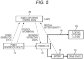
- FIG. 5 is a block diagram illustrating a control block of the floating offshore wind power generation facility 10.
- the remote control operation device 30 acquires a power generation states and a position information from the power generation facility 11, and also acquires a residual battery quantity from the battery 12. When the residual battery quantity of the battery 12 is less than a predetermined value, the remote control operation device 30 issues an operation instruction to the controller 15 so as to make the controller 15 charge the battery 12. When the residual battery quantity of the battery 12 is equal to or higher than a predetermined value, the remote control operation device 30 instructions the controller 15 to transmit power to the floating offshore station 20 via the power transmission line 16.
- the remote control operation device 30 makes the controller 15 transmit position information (for example, a latitude and a longitude) to the floating offshore wind power generation facilities 10.
- position information for example, a latitude and a longitude
- the controller 15 of the floating offshore wind power generation facility 10 moves the floating offshore wind power generation facility 10 to the position by driving the electrically operated drive device 13.
- FIG. 6 is a block diagram illustrating a control block of the remote control operation device 30 (remote control device).
- the remote control operation device 30 includes: a communication unit 31 that communicates with the hydrogen production facility 120 (the floating offshore wind power generation facility 10 and the floating offshore station 20) ; a memory unit 32, a power generation quantity prediction unit 34; a hydrogen production quantity prediction unit 35; a hydrogen production site determination unit 36; a hydrogen recovery planning unit 37; a power generation facility arrangement determination unit 40; an operation evacuation planning unit 41; a movement instruction unit 42, and the like.
- the power generation quantity prediction unit 34 predicts a power generation quantity of the floating offshore wind power generation facility 10 based on weather data 325.
- the hydrogen production quantity prediction unit 35 predicts a hydrogen production quantity based on a prediction quantity calculated by the power generation quantity prediction unit 34.
- the hydrogen production site determination unit 36 determines a hydrogen production site based on hydrogen demand prediction information 321, demand harbor information 322, route data 323, fishery data 324, a hydrogen production quantity, and the hydrogen quantity information of the floating offshore station 20.
- the hydrogen recovery planning unit 37 makes a hydrogen recovery plan based on a hydrogen production site determined by the hydrogen production site determination unit 36, and gives an instruction to the hydrogen carrying vessel 50.
- the power generation facility arrangement determination unit 40 determines the arrangement of each of the floating offshore wind power generation facilities 10 based on the weather data 325 (wind direction, wind speed, solar radiation quantity, atmospheric temperature), and the position information and the residual battery quantities among information of the respective power generation facilities (the floating offshore wind power generation facilities 10) and the floating offshore station 20. In determining the arrangement of the floating offshore wind power generation facilities 10, as described with reference to FIG. 4 , corresponding to a change in the wind direction, the remote control operation device 30 issues an instruction such that the arrangement of the individual floating offshore wind power generation facilities 10 is changed to the optimum arrangement so as to reduce a wake loss that affects the wind turbine disposed on a rear stream side in the wind direction.
- the movement instruction unit 42 instructs each power generation facility and the floating offshore station 20 to move in conformity with the hydrogen production site (the position of the hydrogen production facility 120) determined by the hydrogen production site determination unit 36 and the arrangement configuration of the floating offshore wind power generation facility 10 determined by the power generation facility arrangement determination unit 40. That is, the remote control operation device 30 moves the hydrogen production facility 120 to the hydrogen production site determined by the hydrogen production site determination unit 36, and instructs each power generation facility on detailed information of the arrangement configuration of the respective power generation facilities (floating offshore wind power generation facilities 10) that form the floating offshore wind farm WF at the hydrogen production site.
- FIG. 7 is a diagram illustrating annual changes in an actual power demand.
- FIG. 7 illustrates actual power demand ratios (%) by month (fromApril 2019 to March 2020) with respect to the power demand ratio in northern Japan (Hokkaido), the power demand ratio in the Kanto region (Tokyo), the power demand ratio in southern Japan (Okinawa prefecture) and the power demand ratio on a nationwide average.
- the power demand in winter is about 1.5 times higher than the power demand in summer in northern Japan (Hokkaido).
- the power demand in summer is about 1.5 times higher than the power demand in winter in southern Japan (Okinawa Prefecture).
- the power demand in summer is about 1.5 times higher than the power demand in winter in southern Japan (Okinawa Prefecture).
- the power demand in summer and the power demand in winter are high.
- the operation of producing and supplying hydrogen in South Japan in the summer season and in North Japan in the winter season in conformity with the power demand can contribute to the stable supply of energy. Furthermore, the hydrogen production site and the demand site can be made close to each other and hence, the transportation distance of hydrogen can be shortened. Accordingly, this operation is economically effective.
- FIG. 8 is a diagram illustrating an overall configuration and an operation example of a floating offshore mega solar system 200 according to a second embodiment.
- the difference between the renewable energy power generation system illustrated in FIG. 1 and the renewable energy power generation system illustrated in FIG. 8 lies in whether a power generation device installed in the renewable energy power generation system is the floating offshore wind power generation facility 10 or a floating offshore solar power generation facility 210.
- the floating offshore mega solar system 200 includes: a hydrogen production facility 220 that includes: a floating offshore solar power generation facility 210 that makes use of one or more renewable energies; and a floating offshore station 20 provided with a hydrogen production device that electrolytically produces hydrogen from sea water using electric energy generated by the floating offshore solar power generation facility 210, and a hydrogen storage device; and a remote control operation device 30 (remote control device).
- a plurality of floating offshore solar power generation facilities 210 form a floating offshore mega solar MS.
- renewable energy power generation systems (the floating offshore wind farm system 100 and the floating offshore mega solar system 200) of the present embodiments described above have the following technical features.
- the renewable energy power generation system includes: the hydrogen production facility 120 that includes: a floating offshore power generation facility (for example, floating offshore wind power generation facility 10) that makes use of one or more renewable energies; and the floating offshore station 20 provided with a hydrogen production device (for example, the water electrolysis device 21, the MCH converter 22) that electrolytically produces hydrogen from sea water using electric energy generated by the floating offshore power generation facility, and the hydrogen storage device(for example, the MCH storage tank 23) ; and a remote control device (for example, the remote control operation device 30) that selects a hydrogen production site where hydrogen is produced by the hydrogen production facility 120 based on a hydrogen demand quantity, and performs a remote control of the hydrogen production facility.
- a floating offshore power generation facility for example, floating offshore wind power generation facility 10
- the floating offshore station 20 provided with a hydrogen production device (for example, the water electrolysis device 21, the MCH converter 22) that electrolytically produces hydrogen from sea water using electric energy generated by the floating offshore power generation facility, and the hydrogen storage device(for example, the MCH storage
- the remote control device may preferably select a hydrogen production site near a harbor in the vicinity of a demand site corresponding to a hydrogen demand quantity. With such a configuration, the time and the transportation cost for hydrogen transportation can be reduced.
- the remote control device selects the hydrogen production site based on a determination made in a comprehensive manner based on weather information, a transport distance between the hydrogen production site and a hydrogen demand site, a sea route and a fishery. With such a configuration, energy generated by renewable energy power generation can be efficiently generated and can be transported to a hydrogen demand site.
- the remote control device may preferably select a position where a damage to the hydrogen production facility caused by a typhoon (weather) is avoided in consideration of a predicted route of a typhoon (weather information) . With such a configuration, damage to the renewable energy power generation system can be reduced.
- the remote control device may preferably select, when a hydrogen demand quantity is small, a maintenance harbor close to a current hydrogen production site so as to perform maintenance of the hydrogen production facility. With such a configuration, a cost for maintenance of the renewable energy power generation system can be reduced.
- the floating offshore power generation facility includes: the battery 12 configured to store generated electric energy; and the electrically operated drive device 13, and the renewable energy power generation system operates the electrically operated drive device 13 by discharging the electric energy from the battery 12 when it is necessary to move the floating offshore power generation facility so as to enable the floating offshore power generation facility to move to the hydrogen production site by itself.
- the battery 12 configured to store generated electric energy
- the electrically operated drive device 13 operates the electrically operated drive device 13 by discharging the electric energy from the battery 12 when it is necessary to move the floating offshore power generation facility so as to enable the floating offshore power generation facility to move to the hydrogen production site by itself.
- the remote control device may preferably detect a position of the floating offshore power generation facility by a GPS, and may preferably perform a position control of the floating offshore power generation facility by a radio signal transmitted from the remote control device. With such a configuration, the position of the floating offshore power generation facility can be accurately managed.
- the remote control device at the time of issuing an instruction to move the floating offshore power generation facility to the hydrogen production site, may preferably monitor a residual storage quantity of the battery 12 of each power generation facility of the floating offshore power generation facility, may preferably stop movement of the floating offshore power generation facility when the residual storage quantity becomes equal to or less than a predetermined value, and may preferably resume the movement of the floating offshore power generation facility after charging of the battery by the floating offshore power generation facility is completed.
- the floating offshore power generation facility may preferably be a wind power generation device or a solar power generation device. (see FIG.1 and FIG. 8 ).
- the remote control device may preferably, in a case where the floating offshore power generation facility is a wind power generation device, instruct the wind power generation device to change the arrangement of each power generation facility to an optimum arrangement so as to reduce a wake loss that affects a wind turbine on a rear stream side in a wind direction in response to a change in the wind direction.
- hydrogen may be compressed to a high pressure of approximately several tens of MPs by a compressor and may be stored and transported by a high-pressure container. Further, hydrogen may be absorbed by a hydrogen absorbing alloy, and hydrogen may be stored and transported by a container in which the hydrogen absorbing alloy is contained.
- the hydrogen production facility 120 that is, hydrogen is transported by the hydrogen carrying vessel 50.
- a case may be adopted where hydrogen is transported without using the hydrogen carrying vessel. That is, in this modification, when the hydrogen production facility 120 is moved near a harbor in the vicinity of a demand site, the hydrogen production facility 120 (MCH storage tank 23) and an MCH receiving facility of the harbor are connected to each other by a pipe or the like, and MCH is supplied through the pipe. Toluene obtained after separation of hydrogen from MCH is returned to the hydrogen production facility 120 through a pipe in the same manner.
- the present invention can adopt another modification where, when the hydrogen production facility 120 is moved near a harbor in the vicinity of the demand site, hydrogen is separated from MCH by the hydrogen production facility 120 and hydrogen is supplied to a facility on the land through a pipe.
- this another modification the transportation of MCH or toluene that is a liquid becomes unnecessary.
Landscapes
- Engineering & Computer Science (AREA)
- Chemical & Material Sciences (AREA)
- Life Sciences & Earth Sciences (AREA)
- Sustainable Development (AREA)
- Sustainable Energy (AREA)
- Combustion & Propulsion (AREA)
- Mechanical Engineering (AREA)
- General Engineering & Computer Science (AREA)
- Chemical Kinetics & Catalysis (AREA)
- Electrochemistry (AREA)
- Power Engineering (AREA)
- Wind Motors (AREA)
Abstract
Description
- The present invention relates to a renewable energy power generation system.
- Installation sites on the land where a renewable energy power generation facility can be installed are limited depending on to weather, geographical features and the like. Further, it is often the case that such installation sites where the renewable energy power generation facility can be installed are under a circumstance that a capacity of a power that can be supplied via a power transmission line of a power system is insufficient. Such circumstance is one of factors that obstruct the introduction of a power source acquired by renewable energy power generation. In view of such a circumstance, various types of renewable energy power generation on the sea have been studied.
-
PTL 1 discloses a renewable energy power generation system on the sea. A wind power generator, solar cell panels, and a wave power generator are mounted on a mega float that is a floating body capable of being moored on the sea. Using electric power generated by the wind power generator, solar cell panels or the wave power generator, sea water is subjected to an electrolysis in an energy conversion storage unit such that an oxygen gas and a hydrogen gas are generated by the electrolysis. The generated oxygen gas and hydrogen gas are liquefied and are stored in storage containers. The renewable energy power generation system is configured to be freely movable in conformity with the weather condition or the like. - PTL 2 provides a hydrogen recovery system that includes a hydrogen production plant that uses natural energy most efficiently, is freely movable, and is easily controllable from the land. The hydrogen recovery system can plan an optimal ship allocation schedule of the hydrogen transport tanker.
-
- PTL 1:
JP 2001-59472 A - PTL 2:
JP 2003-72675 A - PTL 1 provides a production device that is freely movable in conformity with weather conditions and the like. In PTL 2, the weather data and the marine observation data, which are factors in changing the position of the hydrogen production plant, are data such as the direction and magnitude of the tide, the wind power, or the sunlight. PTL 2 describes that the natural energy can be collected under the most favorable condition by moving the position of the hydrogen production plant in conformity with these natural conditions.
- However, both literatures focus on power generation efficiency with natural energy and hence, there is a problem in terms of efficiency of a renewable energy power generation system that takes into account a user who uses the energy.
- The present invention has been made to solve the above-described problem, and it is an object of the present invention to provide a renewable energy power generation system capable of improving utilization efficiency of the renewable energy power generation system including a user of energy.
- To achieve the above-mentioned object, a renewable energy power generation system according to the present invention includes: a hydrogen production facility that includes: a floating offshore power generation facility that makes use of one or more renewable energies; and a floating offshore station provided with a hydrogen production device that electrolytically produces hydrogen from sea water using electric energy generated by the floating offshore power generation facility, and a hydrogen storage device; and a remote control device that selects a hydrogen production site where hydrogen is produced by the hydrogen production facility based on a hydrogen demand quantity, and performs a remote control of the hydrogen production facility. Other aspects of the present invention will be described in the embodiments described hereinafter.
- According to the present invention, it is possible to improve the utilization efficiency of a renewable energy power generation system including users of energy.
-
- [
FIG. 1] FIG. 1 is a diagram illustrating an overall configuration and an operation example of a floating offshore wind farm system according to a first embodiment. - [
FIG. 2] FIG. 2 is a diagram illustrating a configuration of a floating offshore wind power generation facility. - [
FIG. 3] FIG. 3 is a diagram illustrating a configuration of a floating offshore station. - [
FIG. 4] FIG. 4 is a diagram illustrating details of a hydrogen production facility of the floating offshore wind farm system. - [
FIG. 5] FIG. 5 is a block diagram illustrating a control block of a floating offshore wind power generation facility. - [
FIG. 6] FIG. 6 is a block diagram illustrating a control block of a remote control operation room. - [
FIG. 7] FIG. 7 is a diagram illustrating annual changes in an actual power demand. - [
FIG. 8] FIG. 8 is a diagram illustrating an overall configuration and an operation example of a floating offshore mega solar system according to a second embodiment. - Embodiments for carrying out the present invention will be described in detail with reference to the drawings when desired.
-
FIG. 1 is a diagram illustrating an overall configuration and an operation example of a floating offshorewind farm system 100 according to a first embodiment. The floating offshorewind farm system 100 according to the first embodiment that forms a renewable energy power generation system includes : ahydrogen production facility 120 that includes: a floating offshore windpower generation facility 10 that makes use of one or more renewable energies; and a floatingoffshore station 20 provided with a hydrogen production device that electrolytically produces hydrogen from sea water using electric energy generated by the floating offshore windpower generation facility 10, and a hydrogen storage device; and a remote control operation device 30 (remote control device). A plurality of floating offshore windpower generation facilities 10 form a floating offshore wind farm WF. - That is, the floating offshore
wind farm system 100 includes thehydrogen production facility 120 and the remotecontrol operation device 30. Thehydrogen production facility 120 includes the floating offshore windpower generation facility 10 and the floatingoffshore station 20. The floating offshore wind farm system WF is formed of the plurality of floating offshore windpower generation facilities 10. In the present embodiment, it is safe to say that thehydrogen production facility 120 is formed of the floating offshore wind farm WF and the floatingoffshore station 20. Thehydrogen production facility 120 may be formed of one floating offshore wind farm WF and a plurality of floatingoffshore stations 20. - The remote
control operation device 30 selects a demand site, and gives an instruction to ahydrogen carrying vessel 50 such that that thehydrogen carrying vessel 50 transports hydrogen to the demand site. Further, the remotecontrol operation device 30 selects a hydrogen production site where hydrogen is produced by the hydrogen production facility 120 (a site of the hydrogen production facility 120) based on a hydrogen demand quantity, and remotely controls the movement of thehydrogen production facility 120. The remotecontrol operation device 30 is installed in a facility on land, for example. However, the remotecontrol operation device 30 may be installed on a ship. - The remote
control operation device 30 has the following technical features. - (1) The remote
control operation device 30 can select a hydrogen production site near a harbor in the vicinity of a demand site corresponding to a hydrogen demand quantity. The remotecontrol operation device 30 issues a movement instruction to thehydrogen production facility 120 in conformity with a demand of hydrogen in the season. The detail of the above-mentioned operation is described later with reference toFIG. 7 . - (2) The remote
control operation device 30 selects the hydrogen production site based on a determination made in a comprehensive manner based on weather information, a transport distance between the hydrogen production site and a hydrogen demand site, a sea route and a fishery. - (3) The remote
control operation device 30 selects a position where a damage to thehydrogen production facility 120 caused by a typhoon is avoided in consideration of a predicted route of a typhoon. - (4) The remote
control operation device 30 selects, when a hydrogen demand quantity is small, a maintenance harbor close to a current hydrogen production site so as to perform maintenance of thehydrogen production facility 120. - (5) The remote
control operation device 30 detects the position of each of the floating offshore windpower generation facilities 10 by a GPS, and performs a position control of the floating offshore windpower generation facilities 10 by a radio signal. - (6) The remote
control operation device 30, at the time of issuing an instruction to move the floating offshore windpower generation facility 10 to the hydrogen production site, monitors a residual storage quantity of the battery of each power generation facility of the floating offshore windpower generation facility 10, stops movement of the floating offshore windpower generation facility 10 when the residual storage quantity becomes equal to or less than a predetermined value, and resumes the movement of the floating offshore windpower generation facility 10 after charging of the battery by the floating offshore windpower generation facility 10 is completed. - (7) The remote
control operation device 30 instructs the wind power generation device to change the arrangement of each power generation facility to an optimum arrangement so as to reduce a wake loss that affects a wind turbine on a rear stream side in a wind direction in response to a change in the wind direction. -
FIG. 2 is a diagram illustrating a configuration of the floating offshore windpower generation facility 10. The individual floating offshore windpower generation facility 10 has apower generation facility 11, abattery 12 and acontroller 15 on afloating body 14. Thefloating body 14 has an electrically operateddrive device 13 that can drive the floating offshore windpower generation facility 10 using the electric energy of thebattery 12. Electric energy from thepower generation facility 11 can be charged into thebattery 12, and can be transmitted to the floatingoffshore station 20 via apower transmission line 16. -
FIG. 3 is a diagram illustrating a configuration of the floatingoffshore station 20. The floatingoffshore station 20 includes, on the floatingbody 24, a water electrolysis device 21 (hydrogen production device) that produces hydrogen by electrolysis of sea water using electric energy, anMCH converter 22 described later, and an MCH storage tank 23 (hydrogen storage device) that stores MCH (methylcyclohexane) produced by theMCH converter 22, acontroller 25, and abattery 26. The floatingbody 24 has an electrically operateddrive device 27 that can drive the floatingoffshore station 20 using the electric energy of thebattery 26. The electric energy transmitted from thepower generation facility 11 via thepower transmission line 16 is charged into thebattery 26. - The
MCH converter 22 is a device that converts toluene into methylcyclohexane (MCH) by making toluene react with hydrogen. As described above, the MCH is stored in theMCH storage tank 23. In the present embodiment, hydrogen is transported in an MCH state by thehydrogen carrying vessel 50. Both toluene and MCH are in a liquid state at a normal temperature and at a normal pressure . A hydrogen gas at a normal temperature and at a normal pressure can be stored and transported as a liquid at a normal temperature and at a normal pressure having a volume that is 1/500 of the volume of the hydrogen gas at a normal temperature and at a normal pressure. Hydrogen is separated from MCH by a catalytic reaction at a hydrogen utilization site that is a transport destination, and is supplied. Toluene that is concurrently obtained can again be utilized as a raw material for producing MCH. -
FIG. 4 is a diagram illustrating details of the hydrogen production facility of the floating offshorewind farm system 100. Electricity is collected from a plurality of floating offshore windpower generation facilities 10, that is, from the floating offshore wind farm WF, and hydrogen is produced by thewater electrolysis device 21 on the floatingoffshore station 20. Then, hydrogen is converted into MCH by theMCH converter 22, and MCH is stored in theMCH storage tank 23. Then, MCH is transferred from theMCH storage tank 23 to thehydrogen carrying vessel 50. - It is effective that, in the floating offshore wind farm WF, the floating offshore wind
power generation facilities 10 are arranged at an interval that is 10 times as large as a rotor diameter D of a wind turbine in the main wind direction and 3 times or more as large as the rotor diameter D of the wind turbine in the direction perpendicular to the main wind direction so as not to obstruct the mutual power generations of the floating offshore windpower generation facilities 10. It is possible to move the floatingoffshore stations 20 to the optimum arrangement corresponding to a change in the wind direction. For example, the rotor diameter D of the wind turbine is at a level of 130 m when an output of the wind turbine is 5 MW. - In the case of
PTL 1, it is described that a plurality of wind power generators can be installed on the mega float. However, the installation position is fixed and hence, the installation position cannot be changed corresponding to the wind direction or the like. To the contrary, the floating offshore wind farm WF according to the present embodiment is formed of the plurality of floating offshore windpower generation facilities 10. Since individual floating offshore windpower generation facility 10 includes the electrically operateddrive device 13, the floating offshore windpower generation facilities 10 can be moved to take the optimum arrangement corresponding to a change in the wind direction. More specifically, corresponding to a change in the wind direction, the remotecontrol operation device 30 issues an instruction such that the arrangement of the individual floating offshore windpower generation facilities 10 of the floating offshore wind farm WF is changed to the optimum arrangement so as to reduce a wake loss that affects the wind turbine disposed on a rear stream side in the wind direction. Note that the wake loss is a phenomenon in which the output of a wind turbine that has entered the leeward side decreases when another wind turbine is located on the windward side of a certain wind turbine. -
FIG. 5 is a block diagram illustrating a control block of the floating offshore windpower generation facility 10. The remotecontrol operation device 30 acquires a power generation states and a position information from thepower generation facility 11, and also acquires a residual battery quantity from thebattery 12. When the residual battery quantity of thebattery 12 is less than a predetermined value, the remotecontrol operation device 30 issues an operation instruction to thecontroller 15 so as to make thecontroller 15 charge thebattery 12. When the residual battery quantity of thebattery 12 is equal to or higher than a predetermined value, the remotecontrol operation device 30 instructions thecontroller 15 to transmit power to the floatingoffshore station 20 via thepower transmission line 16. - In bringing the arrangement of the floating offshore wind
power generation facilities 10 illustrated inFIG. 4 into the optimum arrangement, the remotecontrol operation device 30 makes thecontroller 15 transmit position information (for example, a latitude and a longitude) to the floating offshore windpower generation facilities 10. Upon receiving the position information, thecontroller 15 of the floating offshore windpower generation facility 10 moves the floating offshore windpower generation facility 10 to the position by driving the electrically operateddrive device 13. -
FIG. 6 is a block diagram illustrating a control block of the remote control operation device 30 (remote control device). The remotecontrol operation device 30 includes: acommunication unit 31 that communicates with the hydrogen production facility 120 (the floating offshore windpower generation facility 10 and the floating offshore station 20) ; amemory unit 32, a power generationquantity prediction unit 34; a hydrogen productionquantity prediction unit 35; a hydrogen productionsite determination unit 36; a hydrogenrecovery planning unit 37; a power generation facilityarrangement determination unit 40; an operationevacuation planning unit 41; amovement instruction unit 42, and the like. - The power generation
quantity prediction unit 34 predicts a power generation quantity of the floating offshore windpower generation facility 10 based onweather data 325. The hydrogen productionquantity prediction unit 35 predicts a hydrogen production quantity based on a prediction quantity calculated by the power generationquantity prediction unit 34. - The hydrogen production
site determination unit 36 determines a hydrogen production site based on hydrogendemand prediction information 321, demand harbor information 322,route data 323,fishery data 324, a hydrogen production quantity, and the hydrogen quantity information of the floatingoffshore station 20. The hydrogenrecovery planning unit 37 makes a hydrogen recovery plan based on a hydrogen production site determined by the hydrogen productionsite determination unit 36, and gives an instruction to thehydrogen carrying vessel 50. - The power generation facility
arrangement determination unit 40 determines the arrangement of each of the floating offshore windpower generation facilities 10 based on the weather data 325 (wind direction, wind speed, solar radiation quantity, atmospheric temperature), and the position information and the residual battery quantities among information of the respective power generation facilities (the floating offshore wind power generation facilities 10) and the floatingoffshore station 20. In determining the arrangement of the floating offshore windpower generation facilities 10, as described with reference toFIG. 4 , corresponding to a change in the wind direction, the remotecontrol operation device 30 issues an instruction such that the arrangement of the individual floating offshore windpower generation facilities 10 is changed to the optimum arrangement so as to reduce a wake loss that affects the wind turbine disposed on a rear stream side in the wind direction. - The
movement instruction unit 42 instructs each power generation facility and the floatingoffshore station 20 to move in conformity with the hydrogen production site (the position of the hydrogen production facility 120) determined by the hydrogen productionsite determination unit 36 and the arrangement configuration of the floating offshore windpower generation facility 10 determined by the power generation facilityarrangement determination unit 40. That is, the remotecontrol operation device 30 moves thehydrogen production facility 120 to the hydrogen production site determined by the hydrogen productionsite determination unit 36, and instructs each power generation facility on detailed information of the arrangement configuration of the respective power generation facilities (floating offshore wind power generation facilities 10) that form the floating offshore wind farm WF at the hydrogen production site. -
FIG. 7 is a diagram illustrating annual changes in an actual power demand.FIG. 7 illustrates actual power demand ratios (%) by month (fromApril 2019 to March 2020) with respect to the power demand ratio in northern Japan (Hokkaido), the power demand ratio in the Kanto region (Tokyo), the power demand ratio in southern Japan (Okinawa prefecture) and the power demand ratio on a nationwide average. - To compare the power demands in the respective regions, the power demand in winter is about 1.5 times higher than the power demand in summer in northern Japan (Hokkaido). Conversely, the power demand in summer is about 1.5 times higher than the power demand in winter in southern Japan (Okinawa Prefecture). In the Kanto region (Tokyo), although a change in the power demand between seasons is relatively small, the power demand in summer and the power demand in winter are high.
- From the above, the operation of producing and supplying hydrogen in South Japan in the summer season and in North Japan in the winter season in conformity with the power demand can contribute to the stable supply of energy. Furthermore, the hydrogen production site and the demand site can be made close to each other and hence, the transportation distance of hydrogen can be shortened. Accordingly, this operation is economically effective.
-
FIG. 8 is a diagram illustrating an overall configuration and an operation example of a floating offshore megasolar system 200 according to a second embodiment. The difference between the renewable energy power generation system illustrated inFIG. 1 and the renewable energy power generation system illustrated inFIG. 8 lies in whether a power generation device installed in the renewable energy power generation system is the floating offshore windpower generation facility 10 or a floating offshore solarpower generation facility 210. - The floating offshore mega
solar system 200 according to the second embodiment that forms a renewable energy power generation system includes: ahydrogen production facility 220 that includes: a floating offshore solarpower generation facility 210 that makes use of one or more renewable energies; and a floatingoffshore station 20 provided with a hydrogen production device that electrolytically produces hydrogen from sea water using electric energy generated by the floating offshore solarpower generation facility 210, and a hydrogen storage device; and a remote control operation device 30 (remote control device). A plurality of floating offshore solarpower generation facilities 210 form a floating offshore mega solar MS. These correspondence relationships are substantially equal to those of the first embodiment. - The configuration of the floating offshore mega
solar system 200 illustrated inFIG. 8 and the operation and advantageous effects of the floating offshore megasolar system 200 overlap with the contents described with respect to the first embodiment. Accordingly, the detailed description of the configuration of the floating offshore megasolar system 200 illustrated inFIG. 8 and the operation and advantageous effects of the floating offshore megasolar system 200 are omitted. However, the operation and the advantageous effects of the floating offshorewind farm system 100 described in the first embodiment are substantially as same as those of the floating offshore megasolar system 200 according to the present embodiment. - The renewable energy power generation systems (the floating offshore
wind farm system 100 and the floating offshore mega solar system 200) of the present embodiments described above have the following technical features. - The renewable energy power generation system includes: the
hydrogen production facility 120 that includes: a floating offshore power generation facility (for example, floating offshore wind power generation facility 10) that makes use of one or more renewable energies; and the floatingoffshore station 20 provided with a hydrogen production device (for example, thewater electrolysis device 21, the MCH converter 22) that electrolytically produces hydrogen from sea water using electric energy generated by the floating offshore power generation facility, and the hydrogen storage device(for example, the MCH storage tank 23) ; and a remote control device (for example, the remote control operation device 30) that selects a hydrogen production site where hydrogen is produced by thehydrogen production facility 120 based on a hydrogen demand quantity, and performs a remote control of the hydrogen production facility. According to the present embodiments, it is possible to improve the utilization efficiency of the renewable energy power generation system including energy users. - The remote control device may preferably select a hydrogen production site near a harbor in the vicinity of a demand site corresponding to a hydrogen demand quantity. With such a configuration, the time and the transportation cost for hydrogen transportation can be reduced.
- The remote control device selects the hydrogen production site based on a determination made in a comprehensive manner based on weather information, a transport distance between the hydrogen production site and a hydrogen demand site, a sea route and a fishery. With such a configuration, energy generated by renewable energy power generation can be efficiently generated and can be transported to a hydrogen demand site.
- The remote control device may preferably select a position where a damage to the hydrogen production facility caused by a typhoon (weather) is avoided in consideration of a predicted route of a typhoon (weather information) . With such a configuration, damage to the renewable energy power generation system can be reduced.
- The remote control device may preferably select, when a hydrogen demand quantity is small, a maintenance harbor close to a current hydrogen production site so as to perform maintenance of the hydrogen production facility. With such a configuration, a cost for maintenance of the renewable energy power generation system can be reduced.
- The floating offshore power generation facility includes: the
battery 12 configured to store generated electric energy; and the electrically operateddrive device 13, and the renewable energy power generation system operates the electrically operateddrive device 13 by discharging the electric energy from thebattery 12 when it is necessary to move the floating offshore power generation facility so as to enable the floating offshore power generation facility to move to the hydrogen production site by itself. With such a configuration, it is possible to reduce a fuel cost, a fuel transportation cost and the like when the floating offshore power generation facility moves to the hydrogen production site. - The remote control device may preferably detect a position of the floating offshore power generation facility by a GPS, and may preferably perform a position control of the floating offshore power generation facility by a radio signal transmitted from the remote control device. With such a configuration, the position of the floating offshore power generation facility can be accurately managed.
- The remote control device, at the time of issuing an instruction to move the floating offshore power generation facility to the hydrogen production site, may preferably monitor a residual storage quantity of the
battery 12 of each power generation facility of the floating offshore power generation facility, may preferably stop movement of the floating offshore power generation facility when the residual storage quantity becomes equal to or less than a predetermined value, and may preferably resume the movement of the floating offshore power generation facility after charging of the battery by the floating offshore power generation facility is completed. With such a configuration, it is possible to reduce a fuel cost, a fuel transportation cost and the like when the floating offshore power generation facility moves to the hydrogen production site. - The floating offshore power generation facility may preferably be a wind power generation device or a solar power generation device. (see
FIG.1 andFIG. 8 ). In the floating offshore power generation facility, the remote control device may preferably, in a case where the floating offshore power generation facility is a wind power generation device, instruct the wind power generation device to change the arrangement of each power generation facility to an optimum arrangement so as to reduce a wake loss that affects a wind turbine on a rear stream side in a wind direction in response to a change in the wind direction. With such a configuration, power can be efficiently generated by the renewable energy power generation system. - With respect to the storage and transportation of hydrogen, the case has been described where hydrogen is converted into MCH. However, hydrogen may be compressed to a high pressure of approximately several tens of MPs by a compressor and may be stored and transported by a high-pressure container. Further, hydrogen may be absorbed by a hydrogen absorbing alloy, and hydrogen may be stored and transported by a container in which the hydrogen absorbing alloy is contained.
- Further, the case has been described where the MCH, that is, hydrogen is transported by the
hydrogen carrying vessel 50. However, as a modification, a case may be adopted where hydrogen is transported without using the hydrogen carrying vessel. That is, in this modification, when thehydrogen production facility 120 is moved near a harbor in the vicinity of a demand site, the hydrogen production facility 120 (MCH storage tank 23) and an MCH receiving facility of the harbor are connected to each other by a pipe or the like, and MCH is supplied through the pipe. Toluene obtained after separation of hydrogen from MCH is returned to thehydrogen production facility 120 through a pipe in the same manner. Further, the present invention can adopt another modification where, when thehydrogen production facility 120 is moved near a harbor in the vicinity of the demand site, hydrogen is separated from MCH by thehydrogen production facility 120 and hydrogen is supplied to a facility on the land through a pipe. In this another modification, the transportation of MCH or toluene that is a liquid becomes unnecessary. -
- 10
- floating offshore wind power generation facility
- 11
- power generation facility
- 12
- battery
- 13
- electrically operated drive device
- 14
- floating body
- 15
- controller
- 16
- power transmission line
- 20
- floating offshore station
- 21
- water electrolysis device (hydrogen production device)
- 22
- MCH converter
- 23
- MCH storage tank (hydrogen storage device)
- 24
- floating body
- 25
- controller
- 26
- battery
- 27
- electrically operated drive device
- 30
- remote control operation device (remote control device)
- 31
- communication unit
- 32
- memory unit
- 321
- hydrogen demand prediction information
- 322
- demand harbor Information
- 323
- route data
- 324
- fishery data
- 325
- weather data
- 34
- power generation quantity prediction unit
- 35
- hydrogen production quantity prediction unit
- 36
- hydrogen production site determination unit
- 37
- hydrogen recovery planning unit
- 40
- power generation facility arrangement determination unit
- 41
- operation evacuation planning unit
- 42
- movement instruction unit
- 100
- floating offshore wind farm system
- 120, 220
- hydrogen production facility
- 200
- floating offshore mega solar system
- 210
- floating offshore solar power generation facility
- D
- rotor diameter
- MS
- floating offshore mega solar
- WF
- floating offshore wind farm
Claims (10)
- A renewable energy power generation system comprising:a hydrogen production facility that includes: a floating offshore power generation facility that makes use of one or more renewable energies; and a floating offshore station provided with a hydrogen production device that electrolytically produces hydrogen from sea water using electric energy generated by the floating offshore power generation facility, and a hydrogen storage device; anda remote control device that selects a hydrogen production site where hydrogen is produced by the hydrogen production facility based on a hydrogen demand quantity, and performs a remote control of the hydrogen production facility.
- The renewable energy power generation system according to claim 1, wherein the remote control device selects a site near a harbor disposed in a vicinity of a demand site as the hydrogen production site in conformity with the hydrogen demand quantity.
- The renewable energy power generation system according to claim 1, wherein the remote control device selects the hydrogen production site based on a determination made in a comprehensive manner based on weather information, a transport distance between the hydrogen production site and a hydrogen demand site, a sea route and a fishery.
- The renewable energy power generation system according to claim 1, wherein the remote control device selects a position where a damage to the hydrogen production facility caused by a typhoon is avoided in consideration of a predicted route of a typhoon.
- The renewable energy power generation system according to claim 1, wherein the remote control device selects, when the hydrogen demand quantity is small, a maintenance harbor close to a current hydrogen production site so as to perform maintenance of the hydrogen production facility.
- The renewable energy power generation system according to claim 1, whereinthe floating offshore power generation facility includes: a battery configured to store generated electric energy; and an electrically operated drive device, andthe renewable energy power generation system operates the electrically operated drive device by discharging the electric energy from the battery when it is necessary to move the floating offshore power generation facility so as to enable the floating offshore power generation facility to move to the hydrogen production site by itself.
- The renewable energy power generation system according to claim 1, wherein the remote control device detects a position of the floating offshore power generation facility by a GPS, and performs a position control of the floating offshore power generation facility by a radio signal transmitted from the remote control device.
- The renewable energy power generation system according to claim 6, wherein the remote control device, at a time of issuing an instruction to move the floating offshore power generation facility to the hydrogen production site, monitors a residual storage quantity of the battery of each power generation facility of the floating offshore power generation facility, stops movement of the floating offshore power generation facility when the residual storage quantity becomes equal to or less than a predetermined value, and resumes the movement of the floating offshore power generation facility after charging of the battery by the floating offshore power generation facility is completed.
- The renewable energy power generation system according to any one of claims 1 to 8, wherein the floating offshore power generation facility is a wind power generation device or a solar power generation device.
- The renewable energy power generation system according to claim 1, whereinthe floating offshore power generation facility is a wind power generation device, andthe remote control device instructs the wind power generation device to change arrangement of each power generation facility to an optimum arrangement so as to reduce a wake loss that affects a wind turbine on a rear stream side in a wind direction in response to a change in the wind direction.
Applications Claiming Priority (1)
| Application Number | Priority Date | Filing Date | Title |
|---|---|---|---|
| PCT/JP2020/032570 WO2022044250A1 (en) | 2020-08-28 | 2020-08-28 | Renewable energy power generation system |
Publications (2)
| Publication Number | Publication Date |
|---|---|
| EP4206069A1 true EP4206069A1 (en) | 2023-07-05 |
| EP4206069A4 EP4206069A4 (en) | 2024-06-05 |
Family
ID=80352944
Family Applications (1)
| Application Number | Title | Priority Date | Filing Date |
|---|---|---|---|
| EP20951502.2A Withdrawn EP4206069A4 (en) | 2020-08-28 | 2020-08-28 | RENEWABLE ENERGY-BASED ELECTRIC GENERATION SYSTEM |
Country Status (3)
| Country | Link |
|---|---|
| EP (1) | EP4206069A4 (en) |
| JP (1) | JPWO2022044250A1 (en) |
| WO (1) | WO2022044250A1 (en) |
Families Citing this family (2)
| Publication number | Priority date | Publication date | Assignee | Title |
|---|---|---|---|---|
| CN115793697A (en) * | 2022-12-30 | 2023-03-14 | 中海石油(中国)有限公司 | Floating type fan feedforward attitude control system and method based on sea-air forecast |
| CN116395121A (en) * | 2023-02-28 | 2023-07-07 | 海洋石油工程股份有限公司 | A decentralized offshore wind power hydrogen production storage and transportation integrated system |
Family Cites Families (7)
| Publication number | Priority date | Publication date | Assignee | Title |
|---|---|---|---|---|
| JPH06219372A (en) * | 1992-02-12 | 1994-08-09 | Haruo Kagami | Mooring method for floatable and sinkable floating body |
| DE19714512C2 (en) * | 1997-04-08 | 1999-06-10 | Tassilo Dipl Ing Pflanz | Maritime power plant with manufacturing process for the extraction, storage and consumption of regenerative energy |
| JP2002258943A (en) * | 2001-02-28 | 2002-09-13 | Mitsubishi Heavy Ind Ltd | Offshore remote monitoring system |
| JP2003072675A (en) * | 2001-09-04 | 2003-03-12 | Mitsubishi Heavy Ind Ltd | Hydrogen recovery system with hydrogen production plant |
| JP2016175453A (en) * | 2015-03-18 | 2016-10-06 | 株式会社 ワコム研究所 | Hydrogen generation system and hydrogen recovery system |
| JP2015147573A (en) * | 2015-03-20 | 2015-08-20 | 嘉義 辻本 | Tsunami countermeasure floating structure |
| CN105179170A (en) * | 2015-08-12 | 2015-12-23 | 无锡同春新能源科技有限公司 | Electric quantity increasing device based on complementary power generation of offshore wind power and water floating photovoltaic power station |
-
2020
- 2020-08-28 WO PCT/JP2020/032570 patent/WO2022044250A1/en not_active Ceased
- 2020-08-28 EP EP20951502.2A patent/EP4206069A4/en not_active Withdrawn
- 2020-08-28 JP JP2022545194A patent/JPWO2022044250A1/ja active Pending
Also Published As
| Publication number | Publication date |
|---|---|
| JPWO2022044250A1 (en) | 2022-03-03 |
| WO2022044250A1 (en) | 2022-03-03 |
| EP4206069A4 (en) | 2024-06-05 |
Similar Documents
| Publication | Publication Date | Title |
|---|---|---|
| Boudellal | Power-to-gas: Renewable hydrogen economy for the energy transition | |
| Kleijn et al. | Resource constraints in a hydrogen economy based on renewable energy sources: An exploration | |
| US20120242275A1 (en) | Large-scale ocean mobile solar power generation system | |
| EP4340173A1 (en) | System and method for transporting energy by ship | |
| US20240353805A1 (en) | Application for priority-switching dual-use renewable power plant | |
| Grigoriev et al. | A hybrid power plant based on renewables and electrochemical energy storage and generation systems for decentralized electricity supply of the northern territories | |
| JP2003072675A (en) | Hydrogen recovery system with hydrogen production plant | |
| EP4206069A1 (en) | Renewable energy power generation system | |
| US20230279569A1 (en) | Arrangement to optimize the production of hydrogen | |
| CN115940751A (en) | A floating photovoltaic and hydrogen production coupling system on the sea | |
| RU143216U1 (en) | SYSTEM OF POWER SUPPLY OF FLOATING MEANS OF NAVIGATION SUPPORT OF SHIPPING | |
| JP2025179837A (en) | Low-carbon new energy system with land-sea cooperative multi-energy coupling and optimal dispatch method for land-sea resource cooperation | |
| US20100050500A1 (en) | Maritime Hydrogen or Hydrocarbon Production Facility | |
| Ioannou et al. | A preliminary techno-economic comparison between a grid-connected and non-grid connected offshore floating wind farm | |
| JP2013095273A (en) | Power supply system of buoy | |
| US20210383485A1 (en) | Systems, methods, and apparatuses for facilitaing powering of transoceanic shipping and international energy/chemical supply | |
| JPH0491638A (en) | Energy system | |
| KR102517199B1 (en) | Maritime floating platform for production, storage and offloading of marine green hydrogen | |
| CN117536785A (en) | Comprehensive utilization and conversion system for multiple energies in deep open sea | |
| Steinberger‐Wilckens | Hydrogen as a means of transporting and balancing wind power production | |
| EP4556594A1 (en) | Wind-powered electrolysis arrangement | |
| RU2852632C2 (en) | System and method for transporting electricity by sea vessel | |
| WO2024160971A1 (en) | Large-scale green hydrogen production system for producing hydrogen, ammonia and/or other potential hydrogen derivatives | |
| Banerjee et al. | A Comprehensive Study of Ground Mount and Floating Solar PV System Performance in India for Electric Vehicle Green Charging | |
| Hou | Energy storage systems for vessels |
Legal Events
| Date | Code | Title | Description |
|---|---|---|---|
| STAA | Information on the status of an ep patent application or granted ep patent |
Free format text: STATUS: THE INTERNATIONAL PUBLICATION HAS BEEN MADE |
|
| PUAI | Public reference made under article 153(3) epc to a published international application that has entered the european phase |
Free format text: ORIGINAL CODE: 0009012 |
|
| STAA | Information on the status of an ep patent application or granted ep patent |
Free format text: STATUS: REQUEST FOR EXAMINATION WAS MADE |
|
| 17P | Request for examination filed |
Effective date: 20230228 |
|
| AK | Designated contracting states |
Kind code of ref document: A1 Designated state(s): AL AT BE BG CH CY CZ DE DK EE ES FI FR GB GR HR HU IE IS IT LI LT LU LV MC MK MT NL NO PL PT RO RS SE SI SK SM TR |
|
| DAV | Request for validation of the european patent (deleted) | ||
| DAX | Request for extension of the european patent (deleted) | ||
| A4 | Supplementary search report drawn up and despatched |
Effective date: 20240508 |
|
| RIC1 | Information provided on ipc code assigned before grant |
Ipc: F03D 13/25 20160101ALI20240502BHEP Ipc: F03D 9/19 20160101ALI20240502BHEP Ipc: B63B 35/44 20060101AFI20240502BHEP |
|
| STAA | Information on the status of an ep patent application or granted ep patent |
Free format text: STATUS: THE APPLICATION HAS BEEN WITHDRAWN |
|
| 18W | Application withdrawn |
Effective date: 20250812 |