EP4206043A1 - Anti-theft horn assembly, and vehicle - Google Patents
Anti-theft horn assembly, and vehicle Download PDFInfo
- Publication number
- EP4206043A1 EP4206043A1 EP20960319.0A EP20960319A EP4206043A1 EP 4206043 A1 EP4206043 A1 EP 4206043A1 EP 20960319 A EP20960319 A EP 20960319A EP 4206043 A1 EP4206043 A1 EP 4206043A1
- Authority
- EP
- European Patent Office
- Prior art keywords
- theft
- horn
- theft horn
- vehicle
- mounting bracket
- Prior art date
- Legal status (The legal status is an assumption and is not a legal conclusion. Google has not performed a legal analysis and makes no representation as to the accuracy of the status listed.)
- Granted
Links
Images

Classifications
-
- B—PERFORMING OPERATIONS; TRANSPORTING
- B60—VEHICLES IN GENERAL
- B60R—VEHICLES, VEHICLE FITTINGS, OR VEHICLE PARTS, NOT OTHERWISE PROVIDED FOR
- B60R25/00—Fittings or systems for preventing or indicating unauthorised use or theft of vehicles
- B60R25/10—Fittings or systems for preventing or indicating unauthorised use or theft of vehicles actuating a signalling device
-
- G—PHYSICS
- G10—MUSICAL INSTRUMENTS; ACOUSTICS
- G10K—SOUND-PRODUCING DEVICES; METHODS OR DEVICES FOR PROTECTING AGAINST, OR FOR DAMPING, NOISE OR OTHER ACOUSTIC WAVES IN GENERAL; ACOUSTICS NOT OTHERWISE PROVIDED FOR
- G10K9/00—Devices in which sound is produced by vibrating a diaphragm or analogous element, e.g. fog horns, vehicle hooters or buzzers
- G10K9/18—Details, e.g. bulbs, pumps, pistons, switches or casings
- G10K9/22—Mountings; Casings
-
- B—PERFORMING OPERATIONS; TRANSPORTING
- B60—VEHICLES IN GENERAL
- B60Q—ARRANGEMENT OF SIGNALLING OR LIGHTING DEVICES, THE MOUNTING OR SUPPORTING THEREOF OR CIRCUITS THEREFOR, FOR VEHICLES IN GENERAL
- B60Q5/00—Arrangement or adaptation of acoustic signal devices
-
- G—PHYSICS
- G08—SIGNALLING
- G08B—SIGNALLING SYSTEMS, e.g. PERSONAL CALLING SYSTEMS; ORDER TELEGRAPHS; ALARM SYSTEMS
- G08B3/00—Audible signalling systems, e.g. audible personal calling systems
- G08B3/10—Audible signalling systems, e.g. audible personal calling systems using electric transmission; using electromagnetic transmission
Definitions
- the present invention relates to the automotive technical field and, in particular, to an anti-theft horn assembly and a vehicle.
- a high-pitched anti-theft horn is installed in some vehicles, and is triggered when the vehicle is turned on abnormally. Because of the vehicle layout and sound permeability requirements, an anti-theft horn is generally arranged inside the wing of the vehicle body. At present, a mounting structure of which the mounting and protection are separated is generally adopted, and the mounting structure not only has high self-weight and is not conducive to reducing energy consumption, but also has a mounting point which is exposed to the inner side of the wing. Although the horn cannot be seen at the exterior of the vehicle body, thieves can remove the horn by a simple tool as long as finding the position of the horn, and then pry open the door lock. Without the alarm of the high-pitched horn, thieves have enough time to crack other anti-theft systems.
- the purpose of the present invention is to provide a simple structural and lightweight anti-theft horn assembly, which can prevent thieves from damaging the anti-theft horn without opening a vehicle door, and can improve the anti-theft level of a vehicle.
- an anti-theft horn assembly including an anti-theft horn and a mounting bracket, where the mounting bracket is configured to fix the anti-theft horn at an inner side of a vehicle wing;
- the first fixing part is provided with a first fixing hole, and the first fixing part is fixedly connected to the vehicle cabin by a bolt and the first fixing hole.
- the second fixing part is provided with a second fixing hole, and the second fixing part is fixedly connected to the vehicle wing mounting bracket by a bolt and the second fixing hole.
- the anti-theft horn mounting part is provided with a horn fixing hole, and the anti-theft horn is fixedly connected to the anti-theft horn mounting part by a bolt and the horn fixing hole.
- the anti-theft horn mounting section is further provided with a horn positioning hole.
- the substrate is provided with a plurality of sound leakage holes corresponding to the anti-theft horn.
- the substrate is provided with a wire harness through-hole for arranging a wire harness of the anti-theft horn.
- the substrate is further provided with a wire harness snap for fixing the wire harness of the anti-theft horn.
- the substrate is provided with a lightening hole.
- the present invention further discloses a vehicle including any of the above anti-theft horn assemblies.
- the anti-theft horn assembly and the vehicle described in the present invention have the following beneficial effects:
- 1-Anti-theft horn 101-Wire harness; 2-Mounting bracket; 201-First fixing part; 201a-First fixing hole; 202-Substrate; 202a-Sound leakage hole; 202b-Wire harness through hole; 202c-Wire harness snap; 202d-Lightening hole; 203-Second fixing hole; 203a-Second fixing hole; 204-Anti-theft horn mounting part; 204a-Horn fixing hole; 204b-horn positioning hole; 3-vehicle wing; 4-vehicle front door; 5-A-pillar of vehicle body; 6-mounting gap.
- an embodiment refers to a particular feature, structure, or characteristic that may be included in at least one embodiment of the present invention.
- orientation or positional relationship indicated by the terms “upper”, “lower”, “top” and “bottom” is based on the orientation or positional relationship shown in the accompanying drawings and is only for convenience of description of the present invention and simplification of description, not to indicate or imply that the mentioned device or element must have a particular orientation, be constructed and operated in a particular orientation, and therefore is not to be construed as limiting the invention.
- first and second are used for descriptive purposes only and are not to be understood as indicating or implying relative importance or as implicitly specifying the number of the mentioned technical features.
- the features defined by “first” and “second” may explicitly or implicitly include one or more of the features.
- the terms “first” and “second” are used to distinguish similar objects and are not necessary to describe a particular order or sequence. It should be understood that the data so used may be interchanged under appropriate circumstances, so that embodiments of the present invention described herein may be implemented in an order other than those illustrated or described herein.
- the anti-theft horn is generally arranged inside the wing of the vehicle body.
- a mounting structure of which the mounting and protection are separated is generally adopted to fix the anti-theft horn, and the mounting structure not only has high self-weight, but also has a mounting point which is exposed to the inner side of the wing.
- the horn cannot be seen at the exterior of the vehicle body, by that time thieves can remove the horn by a simple tool as long as finding the position of the horn.
- embodiments of the present application provide an anti-theft horn assembly and a vehicle that can prevent thieves from damaging the anti-theft horn without opening the vehicle door and improve the anti-theft level of the vehicle.
- FIG. 1 is a schematic structural diagram of an optional anti-theft horn assembly according to an embodiment of the present application.
- FIG. 1 includes an anti-theft horn 1 and a mounting bracket 2, where the mounting bracket 2 is configured to fix the anti-theft horn 1 at an inner side of a vehicle wing;
- An anti-theft horn is fixed at an inner side of a vehicle wing through a protection-and-mounting integrated mounting bracket, of which a U-shaped groove structure forms a mounting structure that wraps the anti-theft horn to fix and protect the anti-theft horn and hidden a fixing point of the anti-theft horn in a vehicle cabin. Therefore, the anti-theft horn cannot be removed or damaged on the premise that the mounting bracket is not removed. Meanwhile, a fixing point of the mounting bracket is set on a vehicle wing mounting bracket, so that the mounting bracket cannot be removed without opening the door, thereby preventing thieves from removing or destroying the anti-theft horn without opening the door, effectively protecting the anti-theft horn, and improving the anti-theft coefficient of the vehicle.
- the first fixing part 201 shown in FIG. 1 is provided with a first fixing hole 201a, and the first fixing part 201 is fixedly connected to the vehicle cabin by a bolt and the first fixing hole 201a.
- connection mode between the first fixing part 201 and the vehicle cabin which can be a bolt fixing mode as described above or other connection modes, as long as it can achieve the purpose of fixedly connecting the mounting bracket 2 to the vehicle cabin, where the connection mode is preferably detachable connection, thereby facilitating the removal and maintenance of the anti-theft horn.
- the second fixing part 203 shown in FIG. 1 is provided with a second fixing hole 203a, and the second fixing part 203 is fixedly connected to the vehicle wing mounting bracket by a bolt and the second fixing hole 203a.
- connection mode between the second fixing part 203 and the vehicle wing mounting bracket which can be a bolt fixing mode as described above or other connection modes, as long as it can achieve the purpose of fixedly connecting the mounting bracket 2 to the vehicle wing mounting bracket, where the connection mode is preferably detachable connection, thereby facilitating the removal and maintenance of the anti-theft horn.
- the anti-theft horn mounting part 204 shown in FIG. 1 is provided with a horn fixing hole 204a (shown with FIG. 2 ), and the anti-theft horn 1 is fixedly connected to the anti-theft horn mounting part 204 by a bolt and the horn fixing hole 204a.
- connection mode between the anti-theft horn 1 and the anti-theft horn mounting part 204 which can be a bolt fixing mode as described above or other connection modes, as long as it can achieve the purpose of fixedly connecting the anti-theft horn 1 to the mounting bracket 2, where the connection method is preferably detachable connection, thereby facilitating the removal and maintenance of the anti-theft horn.
- the anti-theft horn mounting part 204 shown in FIG. 1 is further provided with a horn positioning hole 204b, and accordingly, the anti-theft horn 1 should be provided with a positioning part corresponding to the positioning hole 204b, so that the anti-theft horn 1 can be quickly positioned to find a mounting point, thereby facilitating the mounting of the anti-theft horn 1.
- the substrate 202 shown in FIG. 1 is provided with a plurality of sound leakage holes 202a corresponding to the anti-theft horn 1 to meet the sound transmission requirements.
- the arrangement scheme of forming a ring can be used as shown in FIG. 1 , or other arrangement schemes can be used, as long as it can achieve the effect of improving sound transmission.
- the substrate 202 shown in FIG. 1 is provided with a wire harness through-hole 202b for arranging a wire harness 101 of the anti-theft horn 1.
- the substrate 202 shown in FIG. 1 is also provided with a wire harness snap 202c for fixing the wire harness 101 of the anti-theft horn 1.
- the substrate 202 shown in FIG. 1 is provided with a lightening hole 202d.
- the mounting bracket 2 shown in FIG. 1 is integrally formed by stamping a sheet metal.
- the thickness of the sheet metal of the mounting bracket 2 is 1mm ⁇ 1.4mm, preferably 1.2mm, which is not coupled with the vehicle body and the horn frequency, and meets the requirements of rigidity and NVH mode.
- Embodiments of the present application also provide a vehicle including any of the above anti-theft horn assemblies.
- FIG. 4 is a schematic diagram of an application scenario of an anti-theft horn assembly according to an embodiment of the present application.
- a vehicle front door 4 is open; if a mounting method of the prior art is adopted, an anti-theft horn is mounted at an inner side of a vehicle wing 3, thieves can enter the inner side of the vehicle wing from a wheel without opening a vehicle door by dismounting an inner plate of a wheel cover to damage or remove the exposed anti-theft horn, and after the threat of the anti-theft horn is removed, more time is gained to crack other anti-theft systems.
- the anti-theft horn 1 is fixed at the inside of the vehicle wing 3 through the mounting bracket 2, where the anti-theft horn mounting part 204 forms a protective structure that wraps the anti-theft horn 1, so that the anti-theft horn 1 is not exposed to the inside of the vehicle wing 3, and the fixing point of the anti-theft horn 1 is not exposed either. Therefore, on the premise that the mounting bracket 2 is not removed, the anti-theft horn 1 cannot be removed or destroyed.
- the first fixing part 201 of the mounting bracket 2 is fixed to the mounting bracket of the vehicle wing 3, and the special fixing point makes it necessary to open the vehicle door before the removal of the first fixing part 201, and then remove the first fixing part 201 from a mounting gap 6 formed by the vehicle front door 4 and an A-pillar 5 of the vehicle body (shown with FIG. 5 ). Therefore, thieves cannot remove or destroy the anti-theft horn 1 without opening the vehicle door. If a thief wants to destroy the anti-theft horn 1, he must remove the mounting bracket 2 first, however, the mounting bracket 2 must be removed by opening the vehicle front door 4, separating a liner plate of the wing, and removing the mounting bracket 2 from the mounting gap 6. The above actions cannot be completed within 2 minutes, and lock picking will cause the anti-theft horn 1 to alarm, and the above actions are even more impossible to complete in the buzzing sound of the anti-theft horn 1.
- the anti-theft horn assembly and the vehicle described in the present invention have the following beneficial effects:
Landscapes
- Engineering & Computer Science (AREA)
- Physics & Mathematics (AREA)
- Acoustics & Sound (AREA)
- Multimedia (AREA)
- Mechanical Engineering (AREA)
- Fittings On The Vehicle Exterior For Carrying Loads, And Devices For Holding Or Mounting Articles (AREA)
- Burglar Alarm Systems (AREA)
Abstract
Description
- The present invention relates to the automotive technical field and, in particular, to an anti-theft horn assembly and a vehicle.
- In recent years, car theft has been rampant, with approximately 3 million vehicles lost worldwide each year, averaging out to one car stolen every 10 seconds. In response to high premiums caused by vehicle loss, certain organizations find anti-theft experts who are familiar with the thieves' methods to invade vehicles without serious damage to vehicles, and then give the rating about the anti-theft performance of vehicles according to the time of invasion as a criterion for assessing the amount of premiums, and the higher the anti-theft coefficient, the lower the corresponding insured amount.
- In order to increase the market competitiveness, a high-pitched anti-theft horn is installed in some vehicles, and is triggered when the vehicle is turned on abnormally. Because of the vehicle layout and sound permeability requirements, an anti-theft horn is generally arranged inside the wing of the vehicle body. At present, a mounting structure of which the mounting and protection are separated is generally adopted, and the mounting structure not only has high self-weight and is not conducive to reducing energy consumption, but also has a mounting point which is exposed to the inner side of the wing. Although the horn cannot be seen at the exterior of the vehicle body, thieves can remove the horn by a simple tool as long as finding the position of the horn, and then pry open the door lock. Without the alarm of the high-pitched horn, thieves have enough time to crack other anti-theft systems.
- The purpose of the present invention is to provide a simple structural and lightweight anti-theft horn assembly, which can prevent thieves from damaging the anti-theft horn without opening a vehicle door, and can improve the anti-theft level of a vehicle.
- To solve the above technical problems, the present invention discloses an anti-theft horn assembly, including an anti-theft horn and a mounting bracket, where the mounting bracket is configured to fix the anti-theft horn at an inner side of a vehicle wing;
- the mounting bracket includes a first fixing part, a substrate, a second fixing part, and an anti-theft horn mounting part;
- the first fixing part is located at a first end of the substrate for fixedly connecting with a vehicle cabin;
- the second fixing part is located at a second end of the substrate for fixedly connecting with a vehicle wing mounting bracket; and
- the anti-theft horn mounting part is located at an inner side of the substrate, and forms a U-shaped groove structure with the substrate, and the anti-theft horn is mounted in the U-shaped groove structure.
- Optionally, the first fixing part is provided with a first fixing hole, and the first fixing part is fixedly connected to the vehicle cabin by a bolt and the first fixing hole.
- Optionally, the second fixing part is provided with a second fixing hole, and the second fixing part is fixedly connected to the vehicle wing mounting bracket by a bolt and the second fixing hole.
- Optionally, the anti-theft horn mounting part is provided with a horn fixing hole, and the anti-theft horn is fixedly connected to the anti-theft horn mounting part by a bolt and the horn fixing hole.
- Optionally, the anti-theft horn mounting section is further provided with a horn positioning hole.
- Optionally, the substrate is provided with a plurality of sound leakage holes corresponding to the anti-theft horn.
- Optionally, the substrate is provided with a wire harness through-hole for arranging a wire harness of the anti-theft horn.
- Optionally, the substrate is further provided with a wire harness snap for fixing the wire harness of the anti-theft horn.
- Optionally, the substrate is provided with a lightening hole.
- The present invention further discloses a vehicle including any of the above anti-theft horn assemblies.
- By adopting the above technical solutions, the anti-theft horn assembly and the vehicle described in the present invention have the following beneficial effects:
- (1) An anti-theft horn is fixed at an inner side of a vehicle wing by a protection-and-mounting integrated mounting bracket, of which a U-shaped groove structure forms a mounting structure that wraps the anti-theft horn to fix and protect the anti-theft horn and arrange a fixing point of the anti-theft horn inside a vehicle cabin, so that the anti-theft horn cannot be removed or damaged on the premise that the mounting bracket is not removed. Meanwhile, a fixing point of the mounting bracket is set on a vehicle wing mounting bracket, so that the mounting bracket cannot be removed without opening the door, thereby preventing thieves from removing or destroying the anti-theft horn without opening the door, effectively protecting the anti-theft horn, and improving the anti-theft coefficient of the vehicle;
- (2) The anti-theft horn and the mounting bracket are normal standard parts, not anti-theft standard parts, thereby facilitating maintaining;
- (3) The mounting bracket itself is a design in which both the mounting and protection are integrated, with simple structure and low cost, and is conducive to lightweight body design and energy consumption reduction.
- In order to describe the technical solutions in embodiments of the present invention more clearly, the following will make a brief introduction to the drawings needed for describing the embodiments. Apparent1y, the drawings in the following description are merely some embodiments of the present invention, and persons of ordinary skill in the art may still derive other drawings from these accompanying drawings without creative effort.
-
FIG. 1 is a schematic structural diagram of an optional anti-theft horn assembly according to an embodiment of the present application. -
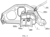
FIG. 2 is a schematic diagram of an optional anti-theft horn mounting part according to an embodiment of the present application. -
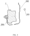
FIG. 3 is a cross-sectional view taken along B-B ofFIG. 1 . -
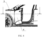
FIG. 4 is a schematic diagram of an application scenario of an optional anti-theft horn assembly according to an embodiment of the present application. -
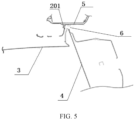
FIG. 5 is a cross-sectional view taken along A-A ofFIG. 4 . - The following are additional descriptions for the accompanying drawings:
1-Anti-theft horn; 101-Wire harness; 2-Mounting bracket; 201-First fixing part; 201a-First fixing hole; 202-Substrate; 202a-Sound leakage hole; 202b-Wire harness through hole; 202c-Wire harness snap; 202d-Lightening hole; 203-Second fixing hole; 203a-Second fixing hole; 204-Anti-theft horn mounting part; 204a-Horn fixing hole; 204b-horn positioning hole; 3-vehicle wing; 4-vehicle front door; 5-A-pillar of vehicle body; 6-mounting gap. - The technical solutions in embodiments of the present invention will be described clearly and comprehensively below in conjunction with the accompanying drawings in embodiments of the present invention. Apparently, the described embodiments are merely a part rather than all embodiments of the present invention. All other embodiments obtained by persons of ordinary skill in the art based on embodiments of the present invention without creative effort shall fall within the protection scope of the present invention.
- Reference herein to "an embodiment" or "embodiment" refers to a particular feature, structure, or characteristic that may be included in at least one embodiment of the present invention. In the description of the present invention, it should be understood that the orientation or positional relationship indicated by the terms "upper", "lower", "top" and "bottom" is based on the orientation or positional relationship shown in the accompanying drawings and is only for convenience of description of the present invention and simplification of description, not to indicate or imply that the mentioned device or element must have a particular orientation, be constructed and operated in a particular orientation, and therefore is not to be construed as limiting the invention. In addition, the terms "first" and "second" are used for descriptive purposes only and are not to be understood as indicating or implying relative importance or as implicitly specifying the number of the mentioned technical features. Thus, the features defined by "first" and "second" may explicitly or implicitly include one or more of the features. Moreover, the terms "first" and "second" are used to distinguish similar objects and are not necessary to describe a particular order or sequence. It should be understood that the data so used may be interchanged under appropriate circumstances, so that embodiments of the present invention described herein may be implemented in an order other than those illustrated or described herein.
- In recent years, car theft has been rampant in Europe and North America, and in response to the high premiums caused by vehicle loss, non-profit insurance organizations have emerged to assess the anti-theft performance of vehicles, such as Thatcham Institute, a non-profit group in the British insurance industry, which conducts insurance assessments for all new cars put into the UK and Sweden. This organization will find anti-theft experts who are familiar with the thieves' methods to invade vehicles without serious damage to the vehicles, and then give the rating about the anti-theft performance of the vehicles according to the time of invasion as a criterion for assessing the amount of premiums, the higher the anti-theft coefficient, the lower the corresponding insured amount, in which an intrusion time of 2 minutes or more is high, 1 to 2 minutes is medium, and less than 1 minute is low.
- In order to improve the anti-theft coefficient of vehicles and increase the competitiveness in the European market, some vehicles choose to be installed with high-pitched anti-theft horn, which triggers the anti-theft horn to alarm when the vehicle is turned on abnormally. Because of the vehicle layout and sound permeability requirements, the anti-theft horn is generally arranged inside the wing of the vehicle body. A mounting structure of which the mounting and protection are separated is generally adopted to fix the anti-theft horn, and the mounting structure not only has high self-weight, but also has a mounting point which is exposed to the inner side of the wing. Although the horn cannot be seen at the exterior of the vehicle body, by that time thieves can remove the horn by a simple tool as long as finding the position of the horn. There may be anti-theft effect for the thieves who commit a crime for the first time, but there may be no effect for thieves who commit a crime for the second time (are slightly experienced) or know the structure. In addition, if an anti-theft fastener is used for anti-theft, the operation difficulty of disassembly and maintenance will be increased.
- In view of the above defects in the prior art, embodiments of the present application provide an anti-theft horn assembly and a vehicle that can prevent thieves from damaging the anti-theft horn without opening the vehicle door and improve the anti-theft level of the vehicle.
- Referring to
FIGS. 1-3 ,FIG. 1 is a schematic structural diagram of an optional anti-theft horn assembly according to an embodiment of the present application.FIG. 1 includes ananti-theft horn 1 and amounting bracket 2, where themounting bracket 2 is configured to fix theanti-theft horn 1 at an inner side of a vehicle wing; - where the
mounting bracket 2 includes afirst fixing part 201, asubstrate 202, asecond fixing part 203, and an anti-thefthorn mounting part 204; - the
first fixing part 201 is located at a first end of thesubstrate 202 for fixedly connecting with a vehicle cabin; - a
second fixing part 203 is located at a second end of thesubstrate 202 for fixedly connecting with a vehicle wing mounting bracket; - the anti-theft
horn mounting part 204 is located at an inner side of thesubstrate 202, and forms a U-shaped groove structure with thesubstrate 202 as shown inFIG. 3 , and theanti-theft horn 1 is mounted in the U-shaped groove structure. - An anti-theft horn is fixed at an inner side of a vehicle wing through a protection-and-mounting integrated mounting bracket, of which a U-shaped groove structure forms a mounting structure that wraps the anti-theft horn to fix and protect the anti-theft horn and hidden a fixing point of the anti-theft horn in a vehicle cabin. Therefore, the anti-theft horn cannot be removed or damaged on the premise that the mounting bracket is not removed. Meanwhile, a fixing point of the mounting bracket is set on a vehicle wing mounting bracket, so that the mounting bracket cannot be removed without opening the door, thereby preventing thieves from removing or destroying the anti-theft horn without opening the door, effectively protecting the anti-theft horn, and improving the anti-theft coefficient of the vehicle.
- As an optional embodiment, the first fixing
part 201 shown inFIG. 1 is provided with afirst fixing hole 201a, and the first fixingpart 201 is fixedly connected to the vehicle cabin by a bolt and thefirst fixing hole 201a. - It should be noted that there is no special limitation on the connection mode between the first fixing
part 201 and the vehicle cabin, which can be a bolt fixing mode as described above or other connection modes, as long as it can achieve the purpose of fixedly connecting the mountingbracket 2 to the vehicle cabin, where the connection mode is preferably detachable connection, thereby facilitating the removal and maintenance of the anti-theft horn. - As an optional embodiment, the
second fixing part 203 shown inFIG. 1 is provided with asecond fixing hole 203a, and thesecond fixing part 203 is fixedly connected to the vehicle wing mounting bracket by a bolt and thesecond fixing hole 203a. - It should be noted that there is no special limitation on the connection mode between the
second fixing part 203 and the vehicle wing mounting bracket, which can be a bolt fixing mode as described above or other connection modes, as long as it can achieve the purpose of fixedly connecting the mountingbracket 2 to the vehicle wing mounting bracket, where the connection mode is preferably detachable connection, thereby facilitating the removal and maintenance of the anti-theft horn. - As an optional embodiment, the anti-theft
horn mounting part 204 shown inFIG. 1 is provided with ahorn fixing hole 204a (shown withFIG. 2 ), and theanti-theft horn 1 is fixedly connected to the anti-thefthorn mounting part 204 by a bolt and thehorn fixing hole 204a. - It should be noted that there is no special limitation on the connection mode between the
anti-theft horn 1 and the anti-thefthorn mounting part 204, which can be a bolt fixing mode as described above or other connection modes, as long as it can achieve the purpose of fixedly connecting theanti-theft horn 1 to the mountingbracket 2, where the connection method is preferably detachable connection, thereby facilitating the removal and maintenance of the anti-theft horn. - As an optional embodiment, the anti-theft
horn mounting part 204 shown inFIG. 1 is further provided with ahorn positioning hole 204b, and accordingly, theanti-theft horn 1 should be provided with a positioning part corresponding to thepositioning hole 204b, so that theanti-theft horn 1 can be quickly positioned to find a mounting point, thereby facilitating the mounting of theanti-theft horn 1. - As an optional embodiment, the
substrate 202 shown inFIG. 1 is provided with a plurality ofsound leakage holes 202a corresponding to theanti-theft horn 1 to meet the sound transmission requirements. - It should be noted that there is no special limitation on the number and the specific arrangement scheme of the
sound leakage holes 202a, the arrangement scheme of forming a ring can be used as shown inFIG. 1 , or other arrangement schemes can be used, as long as it can achieve the effect of improving sound transmission. - As an optional embodiment, the
substrate 202 shown inFIG. 1 is provided with a wire harness through-hole 202b for arranging awire harness 101 of theanti-theft horn 1. - As an optional implementation, the
substrate 202 shown inFIG. 1 is also provided with awire harness snap 202c for fixing thewire harness 101 of theanti-theft horn 1. - As an optional embodiment, the
substrate 202 shown inFIG. 1 is provided with alightening hole 202d. - It should be noted that there is no special limitation on the number and specific shape of the lightening
hole 202d, as long as it can achieve the purpose of weight reduction and ensure the structural strength of the mounting bracket. - As an optional embodiment, the mounting
bracket 2 shown inFIG. 1 is integrally formed by stamping a sheet metal. - In the specific embodiment, the thickness of the sheet metal of the mounting
bracket 2 is 1mm~1.4mm, preferably 1.2mm, which is not coupled with the vehicle body and the horn frequency, and meets the requirements of rigidity and NVH mode. - Embodiments of the present application also provide a vehicle including any of the above anti-theft horn assemblies.
-
FIG. 4 is a schematic diagram of an application scenario of an anti-theft horn assembly according to an embodiment of the present application. As shown inFIG. 4 , a vehiclefront door 4 is open; if a mounting method of the prior art is adopted, an anti-theft horn is mounted at an inner side of avehicle wing 3, thieves can enter the inner side of the vehicle wing from a wheel without opening a vehicle door by dismounting an inner plate of a wheel cover to damage or remove the exposed anti-theft horn, and after the threat of the anti-theft horn is removed, more time is gained to crack other anti-theft systems. - If the anti-theft horn assembly of the present application is adopted, the
anti-theft horn 1 is fixed at the inside of thevehicle wing 3 through the mountingbracket 2, where the anti-thefthorn mounting part 204 forms a protective structure that wraps theanti-theft horn 1, so that theanti-theft horn 1 is not exposed to the inside of thevehicle wing 3, and the fixing point of theanti-theft horn 1 is not exposed either. Therefore, on the premise that the mountingbracket 2 is not removed, theanti-theft horn 1 cannot be removed or destroyed. In addition, the first fixingpart 201 of the mountingbracket 2 is fixed to the mounting bracket of thevehicle wing 3, and the special fixing point makes it necessary to open the vehicle door before the removal of the first fixingpart 201, and then remove the first fixingpart 201 from a mountinggap 6 formed by the vehiclefront door 4 and an A-pillar 5 of the vehicle body (shown withFIG. 5 ). Therefore, thieves cannot remove or destroy theanti-theft horn 1 without opening the vehicle door. If a thief wants to destroy theanti-theft horn 1, he must remove the mountingbracket 2 first, however, the mountingbracket 2 must be removed by opening the vehiclefront door 4, separating a liner plate of the wing, and removing the mountingbracket 2 from the mountinggap 6. The above actions cannot be completed within 2 minutes, and lock picking will cause theanti-theft horn 1 to alarm, and the above actions are even more impossible to complete in the buzzing sound of theanti-theft horn 1. - By adopting the above technical solutions, the anti-theft horn assembly and the vehicle described in the present invention have the following beneficial effects:
- (1) An anti-theft horn is fixed at an inner side of a vehicle wing by a protection-and-mounting integrated mounting bracket, of which a U-shaped groove structure forms a mounting structure that wraps the anti-theft horn to fix and protect the anti-theft horn and hidden a fixing point of the anti-theft horn inside a vehicle cabin, so that the anti-theft horn cannot be removed or damaged on the premise that the mounting bracket is not removed. Meanwhile, a fixing point of the mounting bracket is set on a vehicle wing mounting bracket, so that the mounting bracket cannot be removed without opening the door, thereby preventing thieves from removing or destroying the anti-theft horn without opening the door, effectively protecting the anti-theft horn, and improving the anti-theft coefficient of the vehicle;
- (2) The anti-theft horn and the mounting bracket are normal standard parts, not anti-theft standard parts, thereby facilitating maintaining;
- (3) The mounting bracket itself is a design in which both the mounting and protection are integrated, with simple structure and low cost, and is conducive to lightweight body design and energy consumption reduction.
- The foregoing descriptions are merely preferred embodiments of the present invention, which are not intended to limit the present invention. Any modification, equivalent substitution and improvement made within the spirit and principle of the present invention shall be included in the protection scope of the present invention.
Claims (10)
- An anti-theft horn assembly, comprising an anti-theft horn (1) and a mounting bracket (2), wherein the mounting bracket (2) is configured to fix the anti-theft horn (1) at an inner side of a vehicle wing;the mounting bracket (2) comprises a first fixing part (201), a substrate (202), a second fixing part (203), and an anti-theft horn mounting part (204);the first fixing part (201) is located at a first end of the substrate (202) for fixedly connecting with a vehicle cabin;the second fixing part (203) is located at a second end of the substrate (202) for fixedly connecting with a vehicle wing mounting bracket; andthe anti-theft horn mounting part (204) is located at an inner side of the substrate (202), and forms a U-shaped groove structure with the substrate (202), and the anti-theft horn (1) is mounted in the U-shaped groove structure.
- The anti-theft horn assembly according to claim 1, wherein the first fixing part (201) is provided with a first fixing hole (201a), and the first fixing part (201) is fixedly connected to the vehicle cabin by a bolt and the first fixing hole (201a).
- The anti-theft horn assembly according to claim 1, wherein the second fixing part (203) is provided with a second fixing hole (203a), and the second fixing part (203) is fixedly connected to the vehicle wing mounting bracket by a bolt and the second fixing hole (203a).
- The anti-theft horn assembly according to claim 1, wherein the anti-theft horn mounting part (204) is provided with a horn fixing hole (204a), and the anti-theft horn (1) is fixedly connected to the anti-theft horn mounting part (204) by a bolt and the horn fixing hole (204a).
- The anti-theft horn assembly according to claim 4, wherein the anti-theft horn mounting section (204) is further provided with a horn positioning hole (204b).
- The anti-theft horn assembly according to claim 1, wherein the substrate (202) is provided with a plurality of sound leakage holes (202a) corresponding to the anti-theft horn (1).
- The anti-theft horn assembly according to claim 1, wherein the substrate (202) is provided with a wire harness through-hole (202b) for arranging a wire harness of the anti-theft horn (1).
- The anti-theft horn assembly according to claim 7, wherein the substrate (202) is further provided with a wire harness snap (202c) for fixing the wire harness of the anti-theft horn (1).
- The anti-theft horn assembly according to claim 1, wherein the substrate (202) is provided with a lightening hole (202d).
- A vehicle comprising the anti-theft horn assembly according to any one of claims 1 to 9.
Applications Claiming Priority (1)
| Application Number | Priority Date | Filing Date | Title |
|---|---|---|---|
| PCT/CN2020/126745 WO2022094858A1 (en) | 2020-11-05 | 2020-11-05 | Anti-theft horn assembly, and vehicle |
Publications (4)
| Publication Number | Publication Date |
|---|---|
| EP4206043A1 true EP4206043A1 (en) | 2023-07-05 |
| EP4206043A4 EP4206043A4 (en) | 2023-11-08 |
| EP4206043C0 EP4206043C0 (en) | 2025-01-01 |
| EP4206043B1 EP4206043B1 (en) | 2025-01-01 |
Family
ID=81458405
Family Applications (1)
| Application Number | Title | Priority Date | Filing Date |
|---|---|---|---|
| EP20960319.0A Active EP4206043B1 (en) | 2020-11-05 | 2020-11-05 | Anti-theft horn assembly, and vehicle |
Country Status (3)
| Country | Link |
|---|---|
| EP (1) | EP4206043B1 (en) |
| CN (1) | CN116745172B (en) |
| WO (1) | WO2022094858A1 (en) |
Family Cites Families (17)
| Publication number | Priority date | Publication date | Assignee | Title |
|---|---|---|---|---|
| CN2139906Y (en) * | 1992-11-09 | 1993-08-11 | 刘凤山 | Anti-theft siren for vehicle |
| CN2175149Y (en) * | 1993-04-22 | 1994-08-24 | 张建国 | Alarming device for theft-proof for vehicle |
| US5469135A (en) * | 1994-05-10 | 1995-11-21 | Wolo Manufacturing Corporation | Vehicle security device and alarm |
| JPH11321458A (en) * | 1998-05-20 | 1999-11-24 | Nissan Motor Co Ltd | Vehicle anti-theft horn mounting structure |
| JP2003058959A (en) * | 2001-08-15 | 2003-02-28 | Aota Denshi Kk | Antitheft device for vehicle |
| JP2004106718A (en) * | 2002-09-19 | 2004-04-08 | Fuji Heavy Ind Ltd | Automotive horn mounting structure |
| JP4299075B2 (en) * | 2003-08-26 | 2009-07-22 | 本田技研工業株式会社 | Mounting structure for vehicle horn |
| JP5608031B2 (en) * | 2010-09-30 | 2014-10-15 | 本田技研工業株式会社 | Vehicle approach notification device for electric motorcycles |
| JP5630721B2 (en) * | 2010-12-28 | 2014-11-26 | スズキ株式会社 | Body front structure |
| CN202049732U (en) * | 2011-03-16 | 2011-11-23 | 湖北三环汽车电器有限公司 | Automobile antitheft alarm horn |
| CN203698207U (en) * | 2014-01-27 | 2014-07-09 | 北汽福田汽车股份有限公司 | Anti-theft horn, anti-theft horn fixing support and automobile provided with anti-theft horn and anti-theft horn fixing support |
| CN203933881U (en) * | 2014-05-28 | 2014-11-05 | 北京汽车研究总院有限公司 | A kind of car horn assembly and automobile |
| CN204774592U (en) * | 2015-07-20 | 2015-11-18 | 山西大运汽车制造有限公司 | Engine suspending bracket |
| JP6599300B2 (en) * | 2016-11-18 | 2019-10-30 | 株式会社ホンダアクセス | Mounting structure for articles for vehicles |
| FR3072357B1 (en) * | 2017-10-17 | 2020-10-23 | Renault Sas | AUTOMOTIVE VEHICLE WHEEL ARCH SUPPORTING A SPEAKER MODULE |
| CN207875582U (en) * | 2018-01-11 | 2018-09-18 | 重庆市中兴卫保安服务有限责任公司 | A kind of new-energy automobile burglar alarm |
| CN110271495A (en) * | 2018-03-13 | 2019-09-24 | 标致雪铁龙汽车股份有限公司 | Chamber mount and vehicle for vehicle speakers unit |
-
2020
- 2020-11-05 CN CN202080106974.1A patent/CN116745172B/en active Active
- 2020-11-05 WO PCT/CN2020/126745 patent/WO2022094858A1/en not_active Ceased
- 2020-11-05 EP EP20960319.0A patent/EP4206043B1/en active Active
Also Published As
| Publication number | Publication date |
|---|---|
| EP4206043C0 (en) | 2025-01-01 |
| CN116745172B (en) | 2025-09-19 |
| WO2022094858A1 (en) | 2022-05-12 |
| EP4206043A4 (en) | 2023-11-08 |
| CN116745172A (en) | 2023-09-12 |
| EP4206043B1 (en) | 2025-01-01 |
Similar Documents
| Publication | Publication Date | Title |
|---|---|---|
| US7641267B2 (en) | Harness protecting structure for vehicular horn | |
| US7836618B1 (en) | License plate security frame | |
| EP4206043B1 (en) | Anti-theft horn assembly, and vehicle | |
| RU2415040C1 (en) | Locking device of sliding door of covered freight car | |
| CN222772053U (en) | Vehicle door lock structure and vehicle | |
| CN211454753U (en) | Anti-theft warning device and its equipment box | |
| CN106314113B (en) | Battery fastening structure and power supply unit | |
| CN212458127U (en) | Installation structure of bulletproof glass, bulletproof glass window and armored vehicle | |
| CN209739012U (en) | Intelligent driving area protection isolation device | |
| CN212413262U (en) | Fireproof monitoring camera for aircraft cargo compartment | |
| CN213539992U (en) | Anti-theft door lock structure | |
| CN112519812A (en) | Emergency vehicle window and rail vehicle | |
| CN213601356U (en) | Sulfur Hexafluoride Leak Alarm | |
| CN112477595A (en) | Automobile instrument central control combination device for Internet of vehicles | |
| CN219864649U (en) | Cabinet door structure of anti-theft secret cabinet | |
| US2048810A (en) | Telephone coin collector | |
| CN214729264U (en) | Anti-theft structure for storage battery of electric vehicle | |
| CN223116277U (en) | Luggage compartment door assembly and vehicle | |
| CN211598063U (en) | Locking mechanism for financial service equipment | |
| CN223907992U (en) | True lock pin clutch protection architecture and intelligent lock thereof | |
| JPS6033672Y2 (en) | Car speaker unit | |
| CN221509956U (en) | Warehouse security alarm device | |
| CN221428995U (en) | Camera with automatic alarm function | |
| CN218369529U (en) | Fire-proof box with high heat-proof performance | |
| CN203198931U (en) | External water slot sealing structure of car body |
Legal Events
| Date | Code | Title | Description |
|---|---|---|---|
| STAA | Information on the status of an ep patent application or granted ep patent |
Free format text: STATUS: THE INTERNATIONAL PUBLICATION HAS BEEN MADE |
|
| PUAI | Public reference made under article 153(3) epc to a published international application that has entered the european phase |
Free format text: ORIGINAL CODE: 0009012 |
|
| STAA | Information on the status of an ep patent application or granted ep patent |
Free format text: STATUS: REQUEST FOR EXAMINATION WAS MADE |
|
| 17P | Request for examination filed |
Effective date: 20230330 |
|
| AK | Designated contracting states |
Kind code of ref document: A1 Designated state(s): AL AT BE BG CH CY CZ DE DK EE ES FI FR GB GR HR HU IE IS IT LI LT LU LV MC MK MT NL NO PL PT RO RS SE SI SK SM TR |
|
| A4 | Supplementary search report drawn up and despatched |
Effective date: 20231009 |
|
| RIC1 | Information provided on ipc code assigned before grant |
Ipc: B60R 11/00 20060101ALN20231002BHEP Ipc: B60R 11/02 20060101ALI20231002BHEP Ipc: B60Q 5/00 20060101ALI20231002BHEP Ipc: B60R 25/10 20130101AFI20231002BHEP |
|
| DAV | Request for validation of the european patent (deleted) | ||
| DAX | Request for extension of the european patent (deleted) | ||
| GRAP | Despatch of communication of intention to grant a patent |
Free format text: ORIGINAL CODE: EPIDOSNIGR1 |
|
| STAA | Information on the status of an ep patent application or granted ep patent |
Free format text: STATUS: GRANT OF PATENT IS INTENDED |
|
| RIC1 | Information provided on ipc code assigned before grant |
Ipc: G08B 3/10 20060101ALN20240522BHEP Ipc: B60R 11/00 20060101ALN20240522BHEP Ipc: G10K 9/22 20060101ALI20240522BHEP Ipc: B60R 11/02 20060101ALI20240522BHEP Ipc: B60Q 5/00 20060101ALI20240522BHEP Ipc: B60R 25/10 20130101AFI20240522BHEP |
|
| INTG | Intention to grant announced |
Effective date: 20240618 |
|
| GRAS | Grant fee paid |
Free format text: ORIGINAL CODE: EPIDOSNIGR3 |
|
| GRAA | (expected) grant |
Free format text: ORIGINAL CODE: 0009210 |
|
| STAA | Information on the status of an ep patent application or granted ep patent |
Free format text: STATUS: THE PATENT HAS BEEN GRANTED |
|
| AK | Designated contracting states |
Kind code of ref document: B1 Designated state(s): AL AT BE BG CH CY CZ DE DK EE ES FI FR GB GR HR HU IE IS IT LI LT LU LV MC MK MT NL NO PL PT RO RS SE SI SK SM TR |
|
| REG | Reference to a national code |
Ref country code: GB Ref legal event code: FG4D |
|
| REG | Reference to a national code |
Ref country code: CH Ref legal event code: EP |
|
| REG | Reference to a national code |
Ref country code: DE Ref legal event code: R096 Ref document number: 602020044364 Country of ref document: DE |
|
| REG | Reference to a national code |
Ref country code: IE Ref legal event code: FG4D |
|
| U01 | Request for unitary effect filed |
Effective date: 20250116 |
|
| U07 | Unitary effect registered |
Designated state(s): AT BE BG DE DK EE FI FR IT LT LU LV MT NL PT RO SE SI Effective date: 20250122 |
|
| PG25 | Lapsed in a contracting state [announced via postgrant information from national office to epo] |
Ref country code: PL Free format text: LAPSE BECAUSE OF FAILURE TO SUBMIT A TRANSLATION OF THE DESCRIPTION OR TO PAY THE FEE WITHIN THE PRESCRIBED TIME-LIMIT Effective date: 20250101 |
|
| PG25 | Lapsed in a contracting state [announced via postgrant information from national office to epo] |
Ref country code: ES Free format text: LAPSE BECAUSE OF FAILURE TO SUBMIT A TRANSLATION OF THE DESCRIPTION OR TO PAY THE FEE WITHIN THE PRESCRIBED TIME-LIMIT Effective date: 20250101 |
|
| PG25 | Lapsed in a contracting state [announced via postgrant information from national office to epo] |
Ref country code: IS Free format text: LAPSE BECAUSE OF FAILURE TO SUBMIT A TRANSLATION OF THE DESCRIPTION OR TO PAY THE FEE WITHIN THE PRESCRIBED TIME-LIMIT Effective date: 20250501 Ref country code: NO Free format text: LAPSE BECAUSE OF FAILURE TO SUBMIT A TRANSLATION OF THE DESCRIPTION OR TO PAY THE FEE WITHIN THE PRESCRIBED TIME-LIMIT Effective date: 20250401 |
|
| PG25 | Lapsed in a contracting state [announced via postgrant information from national office to epo] |
Ref country code: HR Free format text: LAPSE BECAUSE OF FAILURE TO SUBMIT A TRANSLATION OF THE DESCRIPTION OR TO PAY THE FEE WITHIN THE PRESCRIBED TIME-LIMIT Effective date: 20250101 |
|
| PG25 | Lapsed in a contracting state [announced via postgrant information from national office to epo] |
Ref country code: GR Free format text: LAPSE BECAUSE OF FAILURE TO SUBMIT A TRANSLATION OF THE DESCRIPTION OR TO PAY THE FEE WITHIN THE PRESCRIBED TIME-LIMIT Effective date: 20250402 |
|
| PG25 | Lapsed in a contracting state [announced via postgrant information from national office to epo] |
Ref country code: CZ Free format text: LAPSE BECAUSE OF FAILURE TO SUBMIT A TRANSLATION OF THE DESCRIPTION OR TO PAY THE FEE WITHIN THE PRESCRIBED TIME-LIMIT Effective date: 20250101 |
|
| PG25 | Lapsed in a contracting state [announced via postgrant information from national office to epo] |
Ref country code: SM Free format text: LAPSE BECAUSE OF FAILURE TO SUBMIT A TRANSLATION OF THE DESCRIPTION OR TO PAY THE FEE WITHIN THE PRESCRIBED TIME-LIMIT Effective date: 20250101 |
|
| PG25 | Lapsed in a contracting state [announced via postgrant information from national office to epo] |
Ref country code: SK Free format text: LAPSE BECAUSE OF FAILURE TO SUBMIT A TRANSLATION OF THE DESCRIPTION OR TO PAY THE FEE WITHIN THE PRESCRIBED TIME-LIMIT Effective date: 20250101 |
|
| PLBE | No opposition filed within time limit |
Free format text: ORIGINAL CODE: 0009261 |
|
| STAA | Information on the status of an ep patent application or granted ep patent |
Free format text: STATUS: NO OPPOSITION FILED WITHIN TIME LIMIT |
|
| 26N | No opposition filed |
Effective date: 20251002 |
|
| U20 | Renewal fee for the european patent with unitary effect paid |
Year of fee payment: 6 Effective date: 20251114 |
|
| PGFP | Annual fee paid to national office [announced via postgrant information from national office to epo] |
Ref country code: GB Payment date: 20251020 Year of fee payment: 6 |