EP4206016A1 - Charging interface for a vehicle, having a charging socket, a vehicle flap and a drive device - Google Patents
Charging interface for a vehicle, having a charging socket, a vehicle flap and a drive device Download PDFInfo
- Publication number
- EP4206016A1 EP4206016A1 EP22216590.4A EP22216590A EP4206016A1 EP 4206016 A1 EP4206016 A1 EP 4206016A1 EP 22216590 A EP22216590 A EP 22216590A EP 4206016 A1 EP4206016 A1 EP 4206016A1
- Authority
- EP
- European Patent Office
- Prior art keywords
- shaft
- vehicle
- link
- charging interface
- flap
- Prior art date
- Legal status (The legal status is an assumption and is not a legal conclusion. Google has not performed a legal analysis and makes no representation as to the accuracy of the status listed.)
- Pending
Links
- 230000007246 mechanism Effects 0.000 claims description 32
- 230000000903 blocking effect Effects 0.000 claims description 10
- 230000001154 acute effect Effects 0.000 claims description 3
- 230000008878 coupling Effects 0.000 description 15
- 238000010168 coupling process Methods 0.000 description 15
- 238000005859 coupling reaction Methods 0.000 description 15
- 238000006073 displacement reaction Methods 0.000 description 8
- 238000007789 sealing Methods 0.000 description 4
- 230000001419 dependent effect Effects 0.000 description 3
- 238000004519 manufacturing process Methods 0.000 description 3
- 230000005540 biological transmission Effects 0.000 description 2
- 238000011161 development Methods 0.000 description 2
- 230000018109 developmental process Effects 0.000 description 2
- 238000005516 engineering process Methods 0.000 description 2
- 238000009434 installation Methods 0.000 description 2
- XLYOFNOQVPJJNP-UHFFFAOYSA-N water Substances O XLYOFNOQVPJJNP-UHFFFAOYSA-N 0.000 description 2
- 230000035508 accumulation Effects 0.000 description 1
- 238000009825 accumulation Methods 0.000 description 1
- 230000009471 action Effects 0.000 description 1
- 230000004913 activation Effects 0.000 description 1
- 230000008859 change Effects 0.000 description 1
- 238000002485 combustion reaction Methods 0.000 description 1
- 238000010276 construction Methods 0.000 description 1
- 230000007613 environmental effect Effects 0.000 description 1
- 239000000945 filler Substances 0.000 description 1
- 239000000446 fuel Substances 0.000 description 1
Images


Classifications
-
- B—PERFORMING OPERATIONS; TRANSPORTING
- B60—VEHICLES IN GENERAL
- B60K—ARRANGEMENT OR MOUNTING OF PROPULSION UNITS OR OF TRANSMISSIONS IN VEHICLES; ARRANGEMENT OR MOUNTING OF PLURAL DIVERSE PRIME-MOVERS IN VEHICLES; AUXILIARY DRIVES FOR VEHICLES; INSTRUMENTATION OR DASHBOARDS FOR VEHICLES; ARRANGEMENTS IN CONNECTION WITH COOLING, AIR INTAKE, GAS EXHAUST OR FUEL SUPPLY OF PROPULSION UNITS IN VEHICLES
- B60K15/00—Arrangement in connection with fuel supply of combustion engines or other fuel consuming energy converters, e.g. fuel cells; Mounting or construction of fuel tanks
- B60K15/03—Fuel tanks
- B60K15/04—Tank inlets
- B60K15/05—Inlet covers
-
- B—PERFORMING OPERATIONS; TRANSPORTING
- B62—LAND VEHICLES FOR TRAVELLING OTHERWISE THAN ON RAILS
- B62D—MOTOR VEHICLES; TRAILERS
- B62D25/00—Superstructure or monocoque structure sub-units; Parts or details thereof not otherwise provided for
- B62D25/24—Superstructure sub-units with access or drainage openings having movable or removable closures; Sealing means therefor
-
- B—PERFORMING OPERATIONS; TRANSPORTING
- B60—VEHICLES IN GENERAL
- B60K—ARRANGEMENT OR MOUNTING OF PROPULSION UNITS OR OF TRANSMISSIONS IN VEHICLES; ARRANGEMENT OR MOUNTING OF PLURAL DIVERSE PRIME-MOVERS IN VEHICLES; AUXILIARY DRIVES FOR VEHICLES; INSTRUMENTATION OR DASHBOARDS FOR VEHICLES; ARRANGEMENTS IN CONNECTION WITH COOLING, AIR INTAKE, GAS EXHAUST OR FUEL SUPPLY OF PROPULSION UNITS IN VEHICLES
- B60K15/00—Arrangement in connection with fuel supply of combustion engines or other fuel consuming energy converters, e.g. fuel cells; Mounting or construction of fuel tanks
- B60K15/03—Fuel tanks
- B60K15/04—Tank inlets
- B60K15/05—Inlet covers
- B60K2015/0515—Arrangements for closing or opening of inlet cover
- B60K2015/0523—Arrangements for closing or opening of inlet cover with sliding connection to the vehicle body
Definitions
- the invention relates to a charging interface for a vehicle, in particular an electrically driven vehicle, with a charging socket for arrangement in an opening in a vehicle body, a vehicle flap for covering and uncovering the opening, and a drive device for moving the vehicle flap according to the definitions in more detail in the preamble of patent claim 1 kind
- a displacement mechanism for a movable body part for covering a tank area and/or a loading trough area of a motor vehicle is known.
- the movable body part represents a flap which can be lowered into a position completely releasing the loading trough area in relation to a fixed body area and can be displaced under the fixed body area.
- a double link guide is provided, in which a first link guide for lowering the flap is arranged on a control carriage, which itself can be moved linearly along a guideway fixed to the vehicle.
- This known displacement mechanism is structurally complex, has a large number of components and requires a high level of assembly effort.
- the DE 44 40 814 A1 discloses a fuel filler flap that can be transferred from a closed position to an open position below the vehicle body.
- guide elements arranged on the tank flap are provided with guide bolts, which are each accommodated in a guide track with a straight and a curved guide section.
- the curved guide section provides a lifting movement, while the straight guide section causes a sliding movement.
- the adjustment movement is transmitted to the tank flap, for example, via a rod which is coupled to a transmission part and via a coupling lever arranged between the transmission part and the guide element.
- Shifting mechanisms for tank flaps and the like that are known from practice and are designed to be more economical in terms of installation space often use what are known as Riser cables or push-pull cables to shift the tank flaps between their operating state closing the tank opening and their operating state releasing the tank recess.
- a closure device for closing an access opening in a motor vehicle body with a push-pull cable is for example in DE 10 2016 110 869 A1 described.
- riser cables In the case of solutions with riser cables or with push-pull ropes, however, it is problematic if such displacement mechanisms are also located in the wet area of a vehicle. Then an undesirably high sealing effort is required in order to avoid soiling and/or icing of the riser cables or the push-pull cables.
- riser cables are flocked to reduce operating noise that impairs the quality impression.
- flocked riser cables require increased forces and torques in order to move the riser cables relative to guides fixed to the housing.
- a preferred object of the technology according to the invention is to reduce or eliminate at least one disadvantage of a previously known solution or to propose an alternative solution.
- a preferred object of the technology disclosed here is a charging interface for a vehicle, in particular an electrically driven vehicle, with a charging socket for arrangement in an opening in a vehicle body, a vehicle flap for covering and uncovering the opening, and a drive device for moving the vehicle flap to provide that is improved in terms of at least one of the following factors: manufacturing time, manufacturing costs, manufacturing complexity, assembly effort, space utilization, operational safety, sustainability, component reliability and resistance to environmental influences.
- a charging interface for a vehicle, in particular an electrically driven vehicle, with a charging socket for arrangement in an opening in a vehicle body, a vehicle flap for at least partially covering and uncovering the opening and a drive device for moving the vehicle flap with a drive unit is proposed.
- a planetary gear with a first shaft, a second shaft and at least one third shaft is provided between a drive shaft of the drive unit and the vehicle flap, the drive shaft being connected to the first shaft.
- the vehicle flap is connected to the second shaft and the charging socket is connected to the third shaft of the planetary gear.
- a vehicle flap and a charging socket can be actuated via a single drive unit in a structurally simple and space-saving manner.
- an electrical plug of a charging station can be connected to an electrical system of the vehicle in order to charge a vehicle battery.
- the vehicle flap is connected to the second shaft of the planetary gear via a lever element and can be moved via the drive unit between a closed position and an open position along link guideways.
- a closed position is understood to mean a position of the vehicle flap in which the vehicle flap flushly closes an opening in a vehicle body of the vehicle.
- the vehicle flap completely exposes the opening of the vehicle body in its open position in order to be able to insert an electrical plug into the charging socket.
- the driving device of the charging interface according to the invention can be implemented with a vehicle lid displacement mechanism for closing and unblocking the opening in the vehicle body, with the possibility that the vehicle lid can be lowered under an adjacent area of the vehicle body.
- the displacement mechanism can include a link guide system, via which the vehicle flap can be adjusted between a position that closes the opening in the vehicle body and a position that opens the opening.
- the vehicle flap of the charging interface according to the invention can be adjusted in comparison to solutions in which the vehicle flap is driven via riser cables or push-pull cables via the lever element with low drive forces and drive torques while at the same time low operating noises and with little design effort against actuating forces that attack the outside of the cover element in the opening direction, durable in its closed position.
- displacement mechanism with a pivotable lever element can also be used in the wet area of a vehicle without complex sealing measures.
- the link guide system can expediently have link guide tracks which are set up to adjust the vehicle flap to a defined extent during a rotary movement of the second shaft and a resulting movement of the lever element.
- the latter adjustment of the vehicle flap within the vehicle body can take place, for example, in the vehicle vertical direction upwards, downwards, in the vehicle longitudinal direction forwards or backwards or also in the vehicle vertical direction and in the vehicle longitudinal direction.
- At least part of the slotted guide tracks of the slotted guide system is preferably provided in the form of slotted hole-like perforated tracks fixed to the body.
- coupling elements can be provided which, depending on the respective application, are permanently connected to the vehicle flap or firmly connected to the lever element and rotatably connected to the vehicle flap or rotatably connected to the lever element, and which during a movement of the lever element are moved in the link guideways.
- the link guideways can move extend away from the opening essentially in the direction of the lifting movement of the vehicle flap.
- link guideways are aligned with one another in such a way that the continued rotary movement of the second shaft of the planetary gear and the associated movement of the lever element result in the actuating movement or pivoting movement of the vehicle flap under the adjacent area of the vehicle body.
- the operative connection between the second shaft and the vehicle flap via the lever element and the coupling elements can be designed in such a way that the axes of rotation of the coupling elements, about which the lever element rotates relative to the connecting link guideways, are at least approximately on a straight line or line of action of force lie.
- the coupling elements can be designed as cylindrical bolts whose longitudinal axes are parallel to the axis of rotation of the lever element with respect to the vehicle flap are.
- the vehicle flap can thus be adjusted in a structurally simple manner with at the same time low actuating forces, since only frictional forces in the contact areas between the coupling elements and the connecting link guideways have to be overcome.
- the vertical lifting movement of the vehicle flap can take place essentially normal to the opening plane of the vehicle body.
- the subsequent adjustment of the vehicle flap into the position releasing the opening also at least approximately includes a rotational movement of the vehicle flap about the axis of rotation of the lever element.
- the axis of rotation of the lever element can run in the vertical or longitudinal direction of the vehicle in order to easily use existing installation space within the vehicle body and to be able to integrate the covering device into existing vehicle systems with little design effort.
- the vehicle flap and the charging socket can be arranged in a closed section of the vehicle body, which is designed with a water drain in a lower area in order to avoid unwanted water accumulations inside the vehicle body.
- a sensor device can also be provided, via which a current location or position of the vehicle flap can be determined.
- the charging socket can be connected to the third shaft of the planetary gear via a lever element and can be moved between a first position and a second position essentially in the transverse direction of the vehicle along a linear guide during a rotary drive by the drive unit.
- an adjustment of the charging socket and an adjustment of the vehicle flap can be coordinated so that the charging socket is in the open position of the vehicle flap in the first position and in the closed position of the vehicle flap in the second position.
- the first position corresponds to a use position in which a distance between a vehicle-outside side of the charging socket and an outside of the vehicle body is smaller than in the second position of the charging socket, which can form a non-use position.
- the drive device of the charging interface according to the invention can be designed with a self-activating blocking mechanism which automatically blocks and releases a rotary movement of the second shaft depending on the rotary positions of the second shaft and the third shaft and which blocks and releases a rotary movement of the third shaft depending on the rotary positions of the second shaft and the third shaft automatically blocks and releases.
- the locking mechanism can be set up so that the third shaft can be driven in rotation by the first shaft and the second shaft is simultaneously held in a rotationally fixed manner by the locking mechanism.
- the locking mechanism can be set up such that the second shaft can be driven in rotation by the first shaft and the third shaft is simultaneously held in a rotationally fixed manner by the locking mechanism.
- Two drives can then be actuated via a single drive unit with little control and regulation effort.
- the mutual drive of the two power take-offs or the second shaft and the third shaft is advantageously carried out without additional control by an operator or by a control device, since the locking mechanism is automatically activated or deactivated depending on the rotational position of the second shaft and the rotational position of the third shaft .
- the locking mechanism comprises a holding element which is firmly connected to the third shaft.
- the retaining element engages in a non-rotatably designed receptacle of the locking mechanism during an operating state of the planetary gear, during which the third shaft is held non-rotatably by the locking mechanism.
- the locking mechanism can include a holding element which is firmly connected to the second shaft and during an operating state of the planetary gear, during which the second shaft is held in a rotationally fixed manner, engages in a rotationally fixed receptacle.
- the receptacles of the blocking mechanism can each represent end regions of link tracks of a blocking slide that can be moved longitudinally between two end positions.
- Such an embodiment of the vehicle according to the invention has a simple design and is characterized by a small number of components, as a result of which the drive device of the vehicle can be assembled with little effort.
- the locking slide which is linearly mounted in the area of a housing, extends in the radial direction of the planetary gear and is equipped with a slotted hole executed.
- the elongated hole can extend in the longitudinal direction of the locking slide in the locking slide.
- the first shaft of the planetary gear can engage in the slot.
- the link tracks can each be provided in end regions of the locking slide that face away from one another. It is possible to open the link tracks in the area of opposite sides of the locking slide and to insert the holding elements into the link tracks of the locking slide via the open areas of the link tracks or to remove them from them during a rotary movement of the second shaft and during a rotary movement of the third shaft.
- the link tracks are each designed with track sections running obliquely towards one another, starting from the open areas.
- the courses of the track sections each enclose an acute angle with a longitudinal direction of the locking slide.
- Further track sections, which run toward one another in the longitudinal direction of the locking slide and include the end regions of the connecting link tracks, can be connected to the courses.
- the blocking slide is linearly displaced by the retaining elements arranged therein via the track sections of the link tracks that run obliquely towards one another until one of the retaining elements is guided out of the link track and the other retaining element in the other link track is held in a rotationally fixed manner in the receptacle of the link track.
- the path section of one link path is adapted to the further path section of the other link path of the locking slide in such a way that the retaining element of the second shaft is inserted into the link path depending on the direction of rotation of the driven first shaft and is held there in a rotationally fixed manner is associated with the holding element of the second shaft.
- the retaining element of the third shaft is simultaneously guided out of the link track that is assigned to the retaining element of the third shaft.
- the track sections of the link tracks are adapted to one another in such a way that the retaining element of the third shaft is inserted into the link track, which is assigned to the retaining element of the third shaft, and held there in a rotationally fixed manner, depending on the direction of rotation of the driven first shaft, while the retaining element of the second shaft is simultaneously guided out of the link track, which is assigned to the holding element of the second shaft.
- a length of the elongated hole of the locking slide in the longitudinal direction of the locking slide and vertical distances between the end areas of the link tracks and the open areas of the link tracks in the longitudinal direction of the locking slide are matched to one another.
- An end area of the elongated hole, which faces away from the end area of the link track in which the holding element of the second shaft or the holding element of the third shaft is held non-rotatably, can rest against a cylindrical outer side of the first shaft. The travel of the locking slide is then limited by the first shaft in a structurally simple manner and without additional construction effort.
- the automatic activation of the locking mechanism is implemented in a structurally simple embodiment of the vehicle according to the invention in that both the second shaft and the third shaft can be driven in rotation by the first shaft when the locking slide is in positions between its two end positions.
- the end areas of the link tracks can each be designed with undercuts, via which the holding elements can each be subjected to a holding force that acts on the holding elements in the direction of the receptacles. Then an automatic loosening of the non-rotatable connection between the holding elements and the link tracks or the locking slide is avoided in a structurally simple way, which can otherwise be caused by vibrations, impacts or the like.
- the outside of the first shaft which interacts with the end regions of the elongated hole, is an outside of a sleeve rotatably mounted on the first shaft, the rotary drive of the first shaft is not impeded by the blocking slide when the locking slide rests on the outside of the first shaft .
- the holding elements can each engage in the link tracks with cylindrical areas. It is then ensured in a simple manner that the drive device of the vehicle according to the invention can be operated with low actuating forces, since the curved outside of the holding elements prevents the holding elements from jamming in the link tracks.
- the first shaft of the planetary gear is designed as a sun gear, the second shaft of the planetary gear as a planet carrier and the third shaft of the planetary gear as a ring gear.
- the planet carrier Rotatably mounted planet gear that meshes with both the sun gear and the ring gear.
- a vehicle 1 is shown with a vehicle body 2 and a drive device 3, wherein the drive device 3 can comprise at least one electric machine or a combination of at least one internal combustion engine and at least one electric machine.
- the vehicle 1 has a charging interface at the rear for charging at least one vehicle battery of the drive device 3 , the charging interface being arranged at an opening 5 in the vehicle body 2 .
- the opening 5 thus represents a so-called charging trough, through which an electrical connector system can be brought into operative connection with a corresponding coupling element, which is arranged inside the vehicle body 2 or below the outer skin of the vehicle 1, in order to be able to charge the vehicle battery of the vehicle 1 .
- a vehicle flap 4 is provided, which is also referred to as a loading flap and is designed essentially as a flat or plate-like element with a carrier.
- In 2 is a in 1 marked area II, which includes the vehicle flap 4, can be seen in more detail.
- the vehicle flap is 4 in 2 shown in an operating state in which the opening 5 is completely closed by the vehicle flap 4. Additionally shows 3 one of the 2 corresponding representation of the vehicle door 4 in an operating state in which the opening 5 is partially released from the vehicle door 4 and in which the vehicle flap 4 is partially pivoted upwards within the vehicle body in the vehicle vertical direction z. in the in 4 shown operating state of the vehicle flap 4, the opening 5 of the vehicle flap 4 is released.
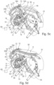
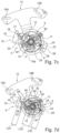
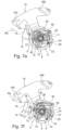
- Figure 5a shows a three-dimensional partial view of a drive device 6 for opening and closing the vehicle flap 4 and for adjusting an at least partially in Figure 5a illustrated charging socket 7, which represents an electrical coupling element for charging an electrical energy store of the vehicle 1.
- the drive device 6 includes a drive unit 6A, which is not shown in detail in the drawing and can be designed as a conventional electric motor.
- the drive device 6 includes a three-shaft planetary gear 8, which has a ring gear 9, a planetary carrier 10 and a sun gear 11.
- Three planet gears 12 are rotatably mounted on the planet carrier 10 and mesh both with the ring gear 9 and with the sun gear 11 .
- a drive shaft of the drive unit 6A of the drive device 6 is operatively connected to the sun wheel 11 , as a result of which a drive torque of the drive unit 6A can be introduced into the planetary gear 8 via the sun wheel 11 .
- Ring gear 9 is connected to vehicle flap 4 via a lever element 13 .
- the vehicle flap 4 can thus be moved from its closed position into its open position by the drive unit 6A of the drive device 6 in the manner described in more detail later.
- the planet carrier 10 is connected to the charging socket 7 via a further lever element 30 in order to move the charging socket 7 along a linear guide 14 from an in Figure 5a non-use position shown in an in Figure 8d to transfer the position of use shown in more detail.
- the drive unit 6A of the drive device 6 drives the sun gear 11 in rotation in the direction of rotation D1, which is why the ring gear 9 is also rotated in the direction of rotation D1.
- the planet carrier 10 is held in a rotationally fixed manner by means of a locking mechanism 15 of the drive device 6 .
- a retaining element 21 firmly connected to the planet carrier 10 engages in a non-rotatable receptacle 22 of a locking slide or locking slide 16 .
- the vehicle flap 4 Due to the rotation of the ring gear 9 , the vehicle flap 4 performs a lifting movement and is thereby moved away from a sealing unit 17 essentially in the vehicle transverse direction y or in the direction of the interior of the vehicle.
- control tracks 18A, 18B are provided in the lever element 13, in each of which a coupling element 19A, 19B engages.
- the coupling elements 19A, 19B are firmly connected to the vehicle flap 4.
- the coupling elements 19A, 19B engage in the vehicle longitudinal direction x in linkage guideways 20 fixed to the body, 201 of a link guide system.
- the link guideways 20, 201 each comprise a first link guideway section 20A or 201A and a second link guideway section 20B or 201B.
- the coupling elements 19A, 19B are each arranged in the first end regions of the control tracks 18A, 18B and the link guide track sections 20A, 201A. If the lever element 13 is moved from the in Figure 5a shown rotary position to the in Figure 5b If the position shown is adjusted or twisted, the coupling elements 19A, 19B slide in the control tracks 18A, 18B and in the link guideway sections 20A, 201A along the link guideways 20, 201 until the coupling elements 19A, 19B reach the second end regions of the control tracks 18A, 18B.
- the vehicle flap 4 carries out the prescribed lifting movement, starting from the closed position in the direction of the vehicle interior.
- the vehicle flap 4 is moved in the vehicle vertical direction z from the Figure 5b position shown in the in Figure 5c position shown under the outer skin of the vehicle body 2 is pivoted. If the drive unit 6A drives the ring gear 9 via the sun gear 11 and the planetary gears 12 further in the direction of rotation D1, the vehicle flap 4 is moved from the in Figure 5c shown position over the in Figure 5d into the in Figure 5e shown position, in which the vehicle flap 4 is arranged in its so-called open position.
- the locking slide 16 is mounted in a linearly displaceable manner in the area of a housing 27 and extends in the radial direction of the planetary gear 8 .
- the locking slide 16 is designed with a slot 28 .
- the elongated hole 28 extends essentially in the longitudinal direction in the locking slide 16.
- the above-described design of the locking mechanism 15, in conjunction with the planetary gear 8, makes it possible to actuate the vehicle flap 4 and the charging socket 7 essentially sequentially one after the other via a single drive unit 6A or a single electric motor and alternately to move the vehicle flap 4 between its open position and its To move the closed position or its closed position and the charging socket 7 between its in Fig. 5f shown, lowered non-use position and their in Fig. 5g shown, towards the operator shifted position of use in the vehicle transverse direction y to adjust.
- the charging socket 7 is moved via the linear guide 14 essentially in the vehicle transverse direction y between the non-use position and the use position.
- An adjustment of the charging socket 7 and an adjustment of the vehicle flap 4 are coordinated so that the charging socket 7 is in the open position of the vehicle flap 4 in its use position and in the closed position of the vehicle flap 4 in its non-use position.
- a perpendicular distance between a side 31 of the charging socket 7 facing the vehicle outward and an outside of the vehicle body 2 is smaller in the use position of the charging socket 7 than in its non-use position, so that the operation is simplified.
- the non-use position of the charging socket 7 is in Fig. 5f shown while the charging socket is 7 in Fig. 5g is shown in its position of use.
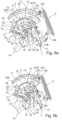
- Figures 6a to 6d each show a side view of the drive device 6 together with the vehicle flap 4 and the charging socket 7 during an operating state progression in which the vehicle flap 4 is transferred from the closed position to its open position and during which the charging socket 7 is in its non-use position.
- Figures 6a to 6d shows that the holding element 21, which is firmly connected to the ring gear 9, during the rotary drive of the ring gear 9 and the associated lifting and pivoting movement of the vehicle flap 4 in Direction of the sliding track 25 of the locking slide 16 is performed.
- the retaining element 21 engages in Figure 6c manner shown in the link path 25 a.
- the locking slide 16 is linearly adjusted by the holding element 21 in the radial direction R8 of the planetary gear 8.
- the locking slide 16 from the in Figure 6c shown position increasingly in the in Figure 6d move the position shown in a translatory manner, in which the holding element 21 is not yet completely arranged in the receptacle 22 . If the holding element 21 is arranged completely in the receptacle 22, the ring gear 9 is blocked by the blocking slide 16 against further rotation in the direction of rotation D1.
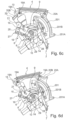
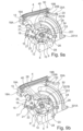
- Figures 7a to 7f each show partial side views of the drive device 6 without the vehicle flap 4 and the charging socket 7.
- the illustrations according to FIG Figures 7a to 7f show the drive device 6 during a change in operating state, starting from an operating state in which the vehicle flap 4 is in its closed position, up to an operating state in which the vehicle flap 4 is positioned in its open position.
- the charging socket 7 remains in its non-use position.
- the further holding element 23 which is fixedly connected to the planet carrier 10, is fixedly arranged in the further receptacle 24 of the locking slide 16.
- the planetary carrier 10 is thus held in a rotationally fixed manner by the locking slide 16 .
- the drive unit 6A of the drive device 6 drives the ring gear 9 in the direction of rotation D1
- the lever element 13 is moved from the position in Figure 7a shown position increasingly in the in Figure 7b shown rotational position adjusted.
- the holding element 21 rotates together with the ring gear 9 in the direction of the link track 25 of the locking slide 16.
- the holding element 21 engages in the link track 25 and adjusts the locking slide 16 in the radial direction R8 of the planetary gear 8.
- the further holding element 23 is used in the in Figure 7c way shown out of the other receptacle 24 of the locking slide 16, so that the non-rotatable connection between the locking slide 16 and the planet carrier 10 is released.
- the sliding tracks 25 and 26 of the locking slide 16 are each provided in the end regions of the locking slide 16 .
- the sliding tracks 25 and 26 are open in the area of opposite sides 16A, 16B of the locking slide 16 .
- the holding elements 21 and 23 can thus be inserted into and removed from the link tracks 25 and 26 via the open areas of the link tracks 25 and 26 during a rotary movement of the ring gear 9 and the planetary carrier 10 .
- the link tracks 25 and 26 each include track sections 34 , 35 which run obliquely towards one another and whose courses enclose an acute angle with a longitudinal direction of the locking slide 16 .
- the track sections 34, 35 are adjoined by further track sections 36, 37, which run towards one another in the longitudinal direction of the locking slide 16 and end in the end regions or receptacles 22, 24 of the link tracks 25, 26.
- the track sections 34, 36 of the link track 25 are adapted to the track sections 35, 37 of the link track 26 in such a way that the retaining element 21 of the ring gear 9, depending on the direction of rotation D1 or the opposite direction of rotation D2 of the driven first shaft or the driven sun gear 11 in the link track 25 is introduced and held there in a rotationally fixed manner, while the holding element 23 of the planetary carrier 10 is simultaneously guided out of the link track 26 .
- track sections 34 to 37 of link tracks 25, 26 are adapted to one another in such a way that retaining element 23 of planetary carrier 10 is inserted into link track 26, depending on direction of rotation D2 of sun gear 11, and is held there in a rotationally fixed manner, while retaining element 21 of ring gear 9 is held at the same time is out of the sliding track 25.
- a length L28 of the slot 28 of the locking slide 16 and vertical distances L25, L26 between the end areas 22, 24 of the link tracks 25, 26 and the open areas of the link tracks 25, 26 in the longitudinal direction of the locking slide 16 are matched to one another.
- the tuning is such that one end area of the elongated hole 28, which faces away from the end area 22 or 24 of the link track 25 or 26, in which the holding element 21 of the ring gear 9 or the holding element 23 of the planet carrier 10 is held in a rotationally fixed manner , rests against a cylindrical outer side 38 of the sun gear shaft 29 and further adjustment of the locking slide in the radial direction R8 of the planetary gear 8 is not possible.
- the locking slide 16 and the planetary gear 8 are matched to one another in such a way that both the ring gear 9 and the planet carrier 10 can be driven in rotation by the sun gear shaft 29 and the sun gear 11 when the locking slide 16 is in positions between its two end positions.
- the end areas or receptacles 22, 24 of the link tracks 25, 26 can each be designed with undercuts.
- the holding elements 21 and 23 can each be subjected to a holding force via the undercuts, which is exerted on the holding elements 21, 23 in the direction of the receptacles 22, 24 attack.
- an undesired release of the operative connection between the locking slide 16 and the retaining elements 21, 23 can be avoided in a structurally simple manner when the retaining elements 21, 23 are each arranged in the receptacles 22, 24.
- the outer side 38 of the sun gear shaft 29, which interacts with the end regions of the elongated hole 28, can be an outer side of a sleeve 39 rotatably mounted on the sun gear shaft 29 in one embodiment of the vehicle 1.
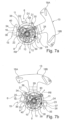
- Figure 8a shows the drive device 6 in an operating state in which the vehicle flap 4 is arranged in a position which almost corresponds to the open position of the vehicle flap 4 and in which the charging socket 7 is in its non-use position.
- the locking slide 16 of the locking mechanism 15 is in Figure 8a arranged in an intermediate longitudinal position in which the ring gear 9 and the planet carrier 10 are driven in rotation with the sun gear 11 rotating, since neither the holding element 21 is arranged in the receptacle 22 nor the further holding element 23 in the further receptacle 24 .
- the rotary drive of the drive unit 6A causes the retaining element 21 of the ring gear 9 from the position in Figure 8a position shown in the in Figure 8b shown position is transferred, in which the holding element 21 is completely arranged in the receptacle 22 of the link track 25 and the ring gear 9 is held by the locking slide 16 in a rotationally fixed manner.
- Figure 8d shows the drive device 6 in an operating state in which the vehicle flap 4 is arranged completely in its open position and the charging socket 7 is transferred to its position of use.
- the further holding element 23 engages in a form-fitting manner in a recess 40 of the locking slide 16, which is provided on the side 16B of the locking slide 16.
- a position of the further holding element 23 and a position of the recess 40 are matched to one another in such a way that the further holding element 23 initiates a linear adjusting movement of the locking slide 16 when there is a positive connection between the further holding element 23 and the locking slide 16 blocks in the area of the recess 40 as long as the sun gear 11 is not driven in rotation in the direction of rotation D2 by the drive unit 6A of the drive device 6 .
- a drive of the sun wheel 11 in the direction of rotation D2 starting from the Figure 8d illustrated operating state of the drive device 6 causes first the charging socket 7 is moved from the use position to its non-use position and then the vehicle flap 4 is transferred from the open position to its closed position.
- Figures 9a to 9d represent each essentially Figures 8a to 8d corresponding side views of the drive device 6 and the vehicle flap 4.
- Figures 9a to 9d the charging socket 7 and the linear guide 14 assigned to it are not shown, in order, in particular, in the operating state of the drive device 6, which is in Figure 8b and in Figure 9b is shown, the position of the further holding element 23 can be inferred from the drawing.
- Figures 10a and 10b each show a side view of part of the drive device 6 without the vehicle flap 4 and the charging socket 7
- Figure 10a an operating state of the drive device 6 is shown, in which the vehicle flap 4 is completely in its open position, while the charging socket 7 is arranged in its non-use position.
- Figure 10b shows Figure 10b the drive device 6 in the operating state in which the vehicle flap 4 is arranged in its open position, while the charging socket 7 is in its position of use.
- the vehicle 1 has an innovative charging socket mechanism in which a rotary drive of a drive unit 6A, such as an electric motor or the like, is controlled via a planetary gear and a self-activating locking mechanism assigned to the planetary gear for actuating the charging socket 7 and the vehicle flap 4.
- a drive unit 6A such as an electric motor or the like
Landscapes
- Engineering & Computer Science (AREA)
- Chemical & Material Sciences (AREA)
- Combustion & Propulsion (AREA)
- Transportation (AREA)
- Mechanical Engineering (AREA)
- Life Sciences & Earth Sciences (AREA)
- Sustainable Development (AREA)
- Sustainable Energy (AREA)
- Electric Propulsion And Braking For Vehicles (AREA)
Abstract
Es wird eine Ladeschnittstelle für ein Fahrzeug (1), insbesondere ein elektrisch antreibbares Fahrzeug (1), mit einer Ladedose (7) zur Anordnung in einer Öffnung (5) einer Fahrzeugkarosserie (2), einer Fahrzeugklappe (4) zum zumindest teilweisen Bedecken und Freigeben der Öffnung (5) sowie einer Antriebsvorrichtung (6) zum Bewegen der Fahrzeugklappe (4) mit einer Antriebseinheit (6A) beschrieben. Zwischen einer Antriebswelle (29) der Antriebseinheit (6A) und der Fahrzeugklappe (4) ist ein Planetengetriebe (8) mit einer ersten Welle (11), einer zweiten Welle (9) und wenigstens einer dritten Welle (10) vorgesehen, wobei die Antriebswelle (29) mit der ersten Welle (11) in Verbindung steht. Die Fahrzeugklappe (4) ist mit der zweiten Welle (9) und die Ladedose (7) ist mit der dritten Welle (10) des Planetengetriebes (8) verbunden ist.Des Weiteren wird ein Fahrzeug mit einer derartigen Ladeschnittstelle beschrieben.A charging interface for a vehicle (1), in particular an electrically driven vehicle (1), with a charging socket (7) for arrangement in an opening (5) in a vehicle body (2), a vehicle flap (4) for at least partially covering and Releasing the opening (5) and a drive device (6) for moving the vehicle door (4) described with a drive unit (6A). A planetary gear (8) with a first shaft (11), a second shaft (9) and at least one third shaft (10) is provided between a drive shaft (29) of the drive unit (6A) and the vehicle flap (4), the drive shaft (29) is connected to the first shaft (11). The vehicle flap (4) is connected to the second shaft (9) and the charging socket (7) is connected to the third shaft (10) of the planetary gear (8). A vehicle with such a charging interface is also described.
Description
Die Erfindung betrifft eine Ladeschnittstelle für ein Fahrzeug, insbesondere ein elektrisch antreibbares Fahrzeug, mit einer Ladedose zur Anordnung in einer Öffnung einer Fahrzeugkarosserie, einer Fahrzeugklappe zum Bedecken und Freigeben der Öffnung sowie einer Antriebsvorrichtung zum Bewegen der Fahrzeugklappe gemäß der im Oberbegriff des Patentanspruches 1 näher definierten Art.The invention relates to a charging interface for a vehicle, in particular an electrically driven vehicle, with a charging socket for arrangement in an opening in a vehicle body, a vehicle flap for covering and uncovering the opening, and a drive device for moving the vehicle flap according to the definitions in more detail in the preamble of patent claim 1 kind
Aus der
Diese bekannte Verlagerungsmechanik ist konstruktiv aufwendig, weist eine hohe Bauteilanzahl auf und erfordert einen hohen Montageaufwand.This known displacement mechanism is structurally complex, has a large number of components and requires a high level of assembly effort.
Die
Diese Lösung ist aufgrund der linearen Verstellbewegung der Stange durch einen unerwünscht hohen Bauraumbedarf gekennzeichnet.Due to the linear adjustment movement of the rod, this solution is characterized by an undesirably large space requirement.
Aus der Praxis bekannte und bauraumgünstiger ausgeführte Verlagerungsmechanismen für Tankklappen und dergleichen nutzen oftmals sogenannte Steigekabel bzw. Zug-Druck-Seile, um die Tankklappen zwischen ihrem die Tanköffnung verschließenden Betriebszustand und ihrem die Tankmulde freigebenden Betriebszustand zu verlagern.Shifting mechanisms for tank flaps and the like that are known from practice and are designed to be more economical in terms of installation space often use what are known as Riser cables or push-pull cables to shift the tank flaps between their operating state closing the tank opening and their operating state releasing the tank recess.
Eine Verschlussvorrichtung zum Verschließen einer Zugriffsöffnung in einer Kraftfahrzeugkarosserie mit einem Zug-Druck-Seil ist beispielsweise in der
Bei Lösungen mit Steigekabeln bzw. mit Zug-Druck-Seilen ist es jedoch problematisch, wenn sich derartige Verlagerungsmechaniken auch im Nassbereich eines Fahrzeuges befinden. Dann ist ein unerwünscht hoher Dichtaufwand erforderlich, um ein Verschmutzen und/oder Vereisen der Steigekabel bzw. der Zug-Druck-Seile zu vermeiden. Zusätzlich werden Steigekabel beflockt, um Betriebsgeräusche zu reduzieren, die eine Qualitätsanmutung beeinträchtigen. Beflockte Steigekabel erfordern jedoch erhöhte Kräfte und Drehmomente, um die Steigekabel gegenüber gehäusefesten Führungen zu verschieben.In the case of solutions with riser cables or with push-pull ropes, however, it is problematic if such displacement mechanisms are also located in the wet area of a vehicle. Then an undesirably high sealing effort is required in order to avoid soiling and/or icing of the riser cables or the push-pull cables. In addition, riser cables are flocked to reduce operating noise that impairs the quality impression. However, flocked riser cables require increased forces and torques in order to move the riser cables relative to guides fixed to the housing.
Es ist eine bevorzugte Aufgabe der erfindungsgemäßen Technologie, zumindest einen Nachteil von einer vorbekannten Lösung zu verringern oder zu beheben oder eine alternative Lösung vorzuschlagen. Es ist insbesondere eine bevorzugte Aufgabe der hier offenbarten Technologie, eine Ladeschnittstelle für ein Fahrzeug, insbesondere ein elektrisch antreibbares Fahrzeug, mit einer Ladedose zur Anordnung in einer Öffnung einer Fahrzeugkarosserie, einer Fahrzeugklappe zum Bedecken und Freigeben der Öffnung sowie einer Antriebsvorrichtung zum Bewegen der Fahrzeugklappe zur Verfügung zu stellen, die hinsichtlich mindestens eines der folgenden Faktoren verbessert ist: Herstellungszeit, Herstellungskosten, Komplexität der Herstellung, Montageaufwand, Bauraumausnutzung, Betriebssicherheit, Nachhaltigkeit, Bauteilzuverlässigkeit und Widerstandsfähigkeit gegenüber Umwelteinflüssen.It is a preferred object of the technology according to the invention to reduce or eliminate at least one disadvantage of a previously known solution or to propose an alternative solution. In particular, a preferred object of the technology disclosed here is a charging interface for a vehicle, in particular an electrically driven vehicle, with a charging socket for arrangement in an opening in a vehicle body, a vehicle flap for covering and uncovering the opening, and a drive device for moving the vehicle flap To provide that is improved in terms of at least one of the following factors: manufacturing time, manufacturing costs, manufacturing complexity, assembly effort, space utilization, operational safety, sustainability, component reliability and resistance to environmental influences.
Die Aufgabe/n wird/werden gelöst mit einer Ladeschnittstelle mit den Merkmalen des Patentanspruches 1. Die abhängigen Patentansprüche stellen bevorzugte Ausgestaltungen dar.The task/s is/are solved with a charging interface having the features of patent claim 1. The dependent patent claims represent preferred developments.
Es wird eine Ladeschnittstelle für ein Fahrzeug, insbesondere ein elektrisch antreibbares Fahrzeug, mit einer Ladedose zur Anordnung in einer Öffnung einer Fahrzeugkarosserie, einer Fahrzeugklappe zum zumindest teilweisen Bedecken und Freigeben der Öffnung sowie einer Antriebsvorrichtung zum Bewegen der Fahrzeugklappe mit einer Antriebseinheit vorgeschlagen. Zwischen einer Antriebswelle der Antriebseinheit und der Fahrzeugklappe ist ein Planetengetriebe mit einer ersten Welle, einer zweiten Welle und wenigstens einer dritten Welle vorgesehen, wobei die Antriebswelle mit der ersten Welle in Verbindung steht. Erfindungsgemäß ist die Fahrzeugklappe mit der zweiten Welle und die Ladedose mit der dritten Welle des Planetengetriebes verbunden.A charging interface for a vehicle, in particular an electrically driven vehicle, with a charging socket for arrangement in an opening in a vehicle body, a vehicle flap for at least partially covering and uncovering the opening and a drive device for moving the vehicle flap with a drive unit is proposed. A planetary gear with a first shaft, a second shaft and at least one third shaft is provided between a drive shaft of the drive unit and the vehicle flap, the drive shaft being connected to the first shaft. According to the invention, the vehicle flap is connected to the second shaft and the charging socket is connected to the third shaft of the planetary gear.
Des Weiteren wird ein Fahrzeug mit einer derartigen Ladeschnittstelle vorgeschlagen.Furthermore, a vehicle with such a charging interface is proposed.
Bei der erfindungsgemäßen Ladeschnittstelle sind eine Fahrzeugklappe und eine Ladedose über eine einzige Antriebseinheit auf konstruktiv einfache und bauraumgünstige Art und Weise betätigbar. Im Bereich der Ladedose ist ein elektrischer Stecker einer Ladestation mit einem elektrischen System des Fahrzeugs in Verbindung bringbar, um eine Fahrzeugbatterie des Fahrzeuges zu laden.In the case of the charging interface according to the invention, a vehicle flap and a charging socket can be actuated via a single drive unit in a structurally simple and space-saving manner. In the area of the charging socket, an electrical plug of a charging station can be connected to an electrical system of the vehicle in order to charge a vehicle battery.
Bei einer konstruktiv einfachen Ausführungsform der erfindungsgemäßen Ladeschnittstelle ist die Fahrzeugklappe über ein Hebelelement mit der zweiten Welle des Planetengetriebes verbunden und über die Antriebseinheit zwischen einer Geschlossenstellung und einer Offenstellung entlang von Kulissenführungsbahnen verfahrbar.In a structurally simple embodiment of the charging interface according to the invention, the vehicle flap is connected to the second shaft of the planetary gear via a lever element and can be moved via the drive unit between a closed position and an open position along link guideways.
Dabei wird vorliegend unter einer Geschlossenstellung eine Position der Fahrzeugklappe verstanden, in der die Fahrzeugklappe eine Öffnung in einer Fahrzeugkarosserie des Fahrzeugs bündig verschließt. Im Unterschied dazu gibt die Fahrzeugklappe die Öffnung der Fahrzeugkarosserie in ihrer Offenstellung vollständig frei, um einen elektrischen Stecker in die Ladedose einführen zu können.In the present case, a closed position is understood to mean a position of the vehicle flap in which the vehicle flap flushly closes an opening in a vehicle body of the vehicle. In contrast to this, the vehicle flap completely exposes the opening of the vehicle body in its open position in order to be able to insert an electrical plug into the charging socket.
Die Antriebsvorrichtung der erfindungsgemäßen Ladeschnittstelle kann mit einem Verlagerungsmechanismus für die Fahrzeugklappe zum Verschließen und Freigeben der Öffnung in der Fahrzeugkarosserie ausgeführt sein, bei dem die Möglichkeit besteht, dass die Fahrzeugklappe unter einen angrenzenden Bereich der Fahrzeugkarosserie absenkbar ist. Der Verlagerungsmechanismus kann ein Kulissenführungssystem umfassen, über das die Fahrzeugklappe zwischen einer die Öffnung der Fahrzeugkarosserie verschließenden Stellung und einer die Öffnung freigebenden Stellung verstellbar ausgeführt ist.The driving device of the charging interface according to the invention can be implemented with a vehicle lid displacement mechanism for closing and unblocking the opening in the vehicle body, with the possibility that the vehicle lid can be lowered under an adjacent area of the vehicle body. The displacement mechanism can include a link guide system, via which the vehicle flap can be adjusted between a position that closes the opening in the vehicle body and a position that opens the opening.
Die Fahrzeugklappe der erfindungsgemäßen Ladeschnittstelle ist im Vergleich zu Lösungen, bei denen der Antrieb der Fahrzeugklappe über Steigekabel oder Zug-Druck-Seile erfolgt, über das Hebelelement mit geringen Antriebskräften und Antriebsmomenten bei gleichzeitig geringen Betriebsgeräuschen verstellbar sowie mit geringem konstruktivem Aufwand gegen Stellkräfte, die von außen am Deckelelement in Öffnungsrichtung angreifen, in ihrer Schließstellung haltbar.The vehicle flap of the charging interface according to the invention can be adjusted in comparison to solutions in which the vehicle flap is driven via riser cables or push-pull cables via the lever element with low drive forces and drive torques while at the same time low operating noises and with little design effort against actuating forces that attack the outside of the cover element in the opening direction, durable in its closed position.
Weiterhin vorteilhaft ist, dass die Verlagerungsmechanik mit einem schwenkbaren Hebelelement ohne aufwändige Dichtmaßnahmen auch im Nassbereich eines Fahrzeuges eingesetzt werden kann.It is also advantageous that the displacement mechanism with a pivotable lever element can also be used in the wet area of a vehicle without complex sealing measures.
Das Kulissenführungssystem kann zweckmäßigerweise Kulissenführungsbahnen aufweisen, die dazu eingerichtet sind, die Fahrzeugklappe während einer Drehbewegung der zweiten Welle und einer daraus resultierenden Bewegung des Hebelelementes in definiertem Umfang zu verstellen. So besteht die Möglichkeit, dass die Fahrzeugklappe während einer Bewegung des Hebelelementes ausgehend von einer ersten Stellung, die das Hebelelement im verschließenden Betriebszustand der Fahrzeugklappe aufweist, in Richtung einer zweiten Stellung, die das Hebelelement im öffnungsfreigebenden Betriebszustand der Fahrzeugklappe aufweist, zuerst im Wesentlichen vertikal bzw. normal aus einer Anlageposition an einen angrenzenden Bereich der Fahrzeugkarosserie in Richtung des Fahrzeuginneren verstellt wird. Anschließend an diese Hub- bzw. Absenkbewegung kann die Fahrzeugklappe im Wesentlichen unter einen angrenzenden Bereich der Fahrzeugkarosserie in einem die Öffnung der Fahrzeugkarosserie freigebenden Umfang weiter verfahren werden.The link guide system can expediently have link guide tracks which are set up to adjust the vehicle flap to a defined extent during a rotary movement of the second shaft and a resulting movement of the lever element. There is thus the possibility that during a movement of the lever element, starting from a first position, which the lever element has in the closing operating state of the vehicle flap, in the direction of a second position, which the lever element has in the opening-releasing operating state of the vehicle flap, the vehicle flap initially moves essentially vertically or horizontally is normally displaced toward the vehicle interior from an abutting position on an adjacent portion of the vehicle body. Subsequent to this lifting or lowering movement, the vehicle flap can essentially be moved further under an adjoining area of the vehicle body to an extent releasing the opening of the vehicle body.
Letztgenannte Verstellung der Fahrzeugklappe innerhalb der Fahrzeugkarosserie kann beispielsweise in Fahrzeughochrichtung nach oben, nach unten, in Fahrzeuglängsrichtung nach vorne oder nach hinten oder auch in Fahrzeughochrichtung und in Fahrzeuglängsrichtung erfolgen.The latter adjustment of the vehicle flap within the vehicle body can take place, for example, in the vehicle vertical direction upwards, downwards, in the vehicle longitudinal direction forwards or backwards or also in the vehicle vertical direction and in the vehicle longitudinal direction.
Bei einer Ausführungsform der erfindungsgemäßen Ladeschnittstelle, die durch eine geringe Bauteilanzahl gekennzeichnet ist, ist zumindest ein Teil der Kulissenführungsbahnen des Kulissenführungssystems vorzugsweise in Form karosseriefester langlochartiger Lochbahnen vorgesehen.In one embodiment of the charging interface according to the invention, which is characterized by a small number of components, at least part of the slotted guide tracks of the slotted guide system is preferably provided in the form of slotted hole-like perforated tracks fixed to the body.
Es besteht auch die Möglichkeit, insbesondere die Kulissenführungsbahnen, über die die Hubbewegung der Fahrzeugklappe erzeugt wird, im Bereich des Hebelelements vorzusehen.There is also the possibility, in particular, of providing the connecting link guideways, via which the lifting movement of the vehicle flap is generated, in the area of the lever element.
Um die erfindungsgemäße Ladeschnittstelle mit möglichst geringem Aufwand montieren zu können, können Koppelelemente vorgesehen sein, die in Abhängigkeit des jeweils vorliegenden Anwendungsfalles fest mit der Fahrzeugklappe oder fest mit dem Hebelelement verbunden und drehbar mit der Fahrzeugklappe oder drehbar mit dem Hebelelement verbunden sind, und die während einer Bewegung des Hebelelements in den Kulissenführungsbahnen bewegt werden.In order to be able to assemble the charging interface according to the invention with as little effort as possible, coupling elements can be provided which, depending on the respective application, are permanently connected to the vehicle flap or firmly connected to the lever element and rotatably connected to the vehicle flap or rotatably connected to the lever element, and which during a movement of the lever element are moved in the link guideways.
Damit bei einer Bewegung des Hebelelementes von seiner ersten Stellung in Richtung seiner zweiten Stellung zunächst die Absenkbewegung bzw. die normale Hubbewegung der Fahrzeugklappe erfolgt, können sich die Kulissenführungsbahnen im Wesentlichen in Richtung der Hubbewegung der Fahrzeugklappe von der Öffnung weg erstrecken.So that when the lever element moves from its first position in the direction of its second position, the lowering movement or the normal lifting movement of the vehicle flap takes place first, the link guideways can move extend away from the opening essentially in the direction of the lifting movement of the vehicle flap.
Bei einer weiteren vorteilhaften Ausführungsform der erfindungsgemäßen Ladeschnittstelle sind weitere Kulissenführungsbahnen vorgesehen, über die die Schwenkbewegung der Fahrzeugklappe ermöglicht wird. Die Verläufe der weiteren Kulissenführungsbahnen sind jeweils winkelig zu den Verläufen der Kulissenführungsbahnen verlaufend ausgerichtet. Dadurch wird auf einfache Art und Weise erreicht, dass aus einer Bewegung des Hebelelements in Richtung seiner zweiten Stellung die Stellbewegung der Fahrzeugklappe unter den angrenzenden Bereich der Fahrzeugkarosserie resultiert, die sich an die Hubbewegung anschließt.In a further advantageous embodiment of the charging interface according to the invention, further link guideways are provided, via which the pivoting movement of the vehicle flap is made possible. The curves of the other link guideways are each aligned at an angle to the courses of the link guideways. This achieves in a simple manner that a movement of the lever element in the direction of its second position results in the adjustment movement of the vehicle flap under the adjacent area of the vehicle body, which follows the lifting movement.
Das bedeutet, dass die Ausrichtung der Kulissenführungsbahnen zueinander so ist, dass aus der fortgesetzten Drehbewegung der zweiten Welle des Planetengetriebes und der damit verbundenen Bewegung des Hebelelements die Stellbewegung bzw. Schwenkbewegung der Fahrzeugklappe unter den angrenzenden Bereich der Fahrzeugkarosserie resultiert.This means that the link guideways are aligned with one another in such a way that the continued rotary movement of the second shaft of the planetary gear and the associated movement of the lever element result in the actuating movement or pivoting movement of the vehicle flap under the adjacent area of the vehicle body.
Die Wirkverbindung zwischen der zweiten Welle und der Fahrzeugklappe über das Hebelelement und die Koppelelemente kann so ausgeführt sein, dass die Drehachsen der Koppelelemente, um die das Hebelelement jeweils gegenüber den Kulissenführungsbahnen rotiert, in der Schließlage der Fahrzeugklappe jeweils wenigstens annähernd auf einer geraden Linie bzw. Kraftwirkungslinie liegen.The operative connection between the second shaft and the vehicle flap via the lever element and the coupling elements can be designed in such a way that the axes of rotation of the coupling elements, about which the lever element rotates relative to the connecting link guideways, are at least approximately on a straight line or line of action of force lie.
Dadurch wird erreicht, dass das Hebelelement in der Schließlage der Fahrzeugklappe sich in einer sogenannten Strecklage befindet. Damit ist die Fahrzeugklappe in der geschlossenen Position durch die gleichzeitige Strecklage gegen Einflüsse von außen gesichert. Derartige äußere Einflüsse stellen beispielsweise ein manuelles Eindrücken der Fahrzeugklappe, ein manuelles Verschieben der Fahrzeugklappe, Krafteinwirkungen auf die Fahrzeugklappe durch die Luftumströmung der Fahrzeugkarosserie während einer Fahrt und dergleichen dar.This ensures that the lever element is in a so-called extended position in the closed position of the vehicle flap. The vehicle flap is thus secured in the closed position against external influences by the simultaneous extended position. Such external influences are, for example, manual pressing in of the vehicle flap, manual displacement of the vehicle flap, forces acting on the vehicle flap due to the air flowing around the vehicle body while driving and the like.
Zusätzlich wird durch die Strecklage des Hebelelementes an der Fahrzeugklappe eine Schließkraft angelegt und die Fahrzeugklappe in Anlage mit einer optionalen Dichteinheit gehalten. Somit wird mit geringem Aufwand gewährleistet, dass die Fahrzeugklappe in geschlossenem Zustand der Öffnung den Innenraum der Fahrzeugkarosserie gegen den Eintritt von Schmutz und Feuchtigkeit abdichtet.In addition, due to the extended position of the lever element, a closing force is applied to the vehicle flap and the vehicle flap is held in contact with an optional sealing unit. This ensures with little effort that the vehicle flap seals the interior of the vehicle body against the ingress of dirt and moisture when the opening is in the closed state.
Die Koppelelemente können als zylindrische Bolzen ausgeführt sein, deren Längsachsen parallel zur Rotationsachse des Hebelelements gegenüber der Fahrzeugklappe sind. Die Fahrzeugklappe ist somit auf konstruktiv einfache Art und Weise mit gleichzeitig geringen Stellkräften verstellbar, da lediglich Reibkräfte in den Anlagebereichen zwischen den Koppelelementen und den Kulissenführungsbahnen zu überwinden sind.The coupling elements can be designed as cylindrical bolts whose longitudinal axes are parallel to the axis of rotation of the lever element with respect to the vehicle flap are. The vehicle flap can thus be adjusted in a structurally simple manner with at the same time low actuating forces, since only frictional forces in the contact areas between the coupling elements and the connecting link guideways have to be overcome.
Die vertikale Hubbewegung der Fahrzeugklappe kann im Wesentlichen normal zur Öffnungsebene der Fahrzeugkarosserie erfolgen. Zusätzlich besteht die Möglichkeit, dass die sich daran anschließende Verstellung der Fahrzeugklappe in die die Öffnung freigebende Stellung auch wenigstens annähernd eine Drehbewegung der Fahrzeugklappe um die Drehachse des Hebelelementes einschließt.The vertical lifting movement of the vehicle flap can take place essentially normal to the opening plane of the vehicle body. In addition, there is the possibility that the subsequent adjustment of the vehicle flap into the position releasing the opening also at least approximately includes a rotational movement of the vehicle flap about the axis of rotation of the lever element.
Die Drehachse des Hebelelements kann in Abhängigkeit des jeweils vorliegenden Anwendungsfalles in Fahrzeughoch- oder in Fahrzeuglängsrichtung verlaufen, um vorhandene Bauräume innerhalb der Fahrzeugkarosserie auf einfache Art und Weise zu nutzen und die Abdeckvorrichtung mit geringem konstruktivem Aufwand in bestehende Fahrzeugsysteme integrieren zu können.Depending on the respective application, the axis of rotation of the lever element can run in the vertical or longitudinal direction of the vehicle in order to easily use existing installation space within the vehicle body and to be able to integrate the covering device into existing vehicle systems with little design effort.
Die Fahrzeugklappe und die Ladedose können in einem geschlossenen Abschnitt der Fahrzeugkarosserie angeordnet sein, der an einem unteren Bereich mit einem Wasserablauf ausgeführt ist, um unerwünschte Wasseransammlungen im Inneren der Fahrzeugkarosserie zu vermeiden.The vehicle flap and the charging socket can be arranged in a closed section of the vehicle body, which is designed with a water drain in a lower area in order to avoid unwanted water accumulations inside the vehicle body.
Des Weiteren kann auch eine Sensoreinrichtung vorgesehen sein, über die eine aktuelle Lage bzw. Position der Fahrzeugklappe ermittelbar ist.Furthermore, a sensor device can also be provided, via which a current location or position of the vehicle flap can be determined.
Die Ladedose kann über ein Hebelelement mit der dritten Welle des Planetengetriebes in Verbindung stehen und während eines rotatorischen Antriebs durch die Antriebseinheit im Wesentlichen in Fahrzeugquerrichtung entlang einer Linearführung zwischen einer ersten Position und einer zweiten Position verfahrbar sein. Zusätzlich können eine Verstellung der Ladedose und eine Verstellung der Fahrzeugklappe so aufeinander abgestimmt sein, dass die Ladedose in der Offenstellung der Fahrzeugklappe in der ersten Position und in der Geschlossenstellung der Fahrzeugklappe in der zweiten Position vorliegt. Dabei ist es zweckmäßig, wenn die erste Position einer Gebrauchsposition entspricht, in der ein Abstand zwischen einer fahrzeugauswärtigen Seite der Ladedose und einer Außenseite der Fahrzeugkarosserie kleiner ist als in der zweiten Position der Ladedose, welche eine Nichtgebrauchsposition bilden kann.The charging socket can be connected to the third shaft of the planetary gear via a lever element and can be moved between a first position and a second position essentially in the transverse direction of the vehicle along a linear guide during a rotary drive by the drive unit. In addition, an adjustment of the charging socket and an adjustment of the vehicle flap can be coordinated so that the charging socket is in the open position of the vehicle flap in the first position and in the closed position of the vehicle flap in the second position. It is expedient if the first position corresponds to a use position in which a distance between a vehicle-outside side of the charging socket and an outside of the vehicle body is smaller than in the second position of the charging socket, which can form a non-use position.
Damit ist wiederum mit geringem konstruktiven Aufwand gewährleistet, dass ein elektrischer Stecker von einer Bedienperson auf einfache Art und Weise in die Ladedose einsteckbar bzw. aus dieser entnehmbar ist.This in turn ensures, with little structural effort, that an electrical plug can be plugged into or removed from the charging socket in a simple manner by an operator.
Die Antriebsvorrichtung der erfindungsgemäßen Ladeschnittstelle kann mit einem selbstaktivierenden Sperrmechanismus ausgeführt sein, der eine Drehbewegung der zweiten Welle in Abhängigkeit von Drehstellungen der zweiten Welle und der dritten Welle selbsttätig sperrt und freigibt und der eine Drehbewegung der dritten Welle in Abhängigkeit von Drehstellungen der zweiten Welle und der dritten Welle selbsttätig sperrt und freigibt.The drive device of the charging interface according to the invention can be designed with a self-activating blocking mechanism which automatically blocks and releases a rotary movement of the second shaft depending on the rotary positions of the second shaft and the third shaft and which blocks and releases a rotary movement of the third shaft depending on the rotary positions of the second shaft and the third shaft automatically blocks and releases.
Dabei kann der Sperrmechanismus dazu eingerichtet sein, dass die dritte Welle von der ersten Welle rotatorisch antreibbar ist und die zweite Welle vom Sperrmechanismus gleichzeitig drehfest gehalten ist. Zusätzlich kann der Sperrmechanismus dazu eingerichtet sein, dass die zweite Welle von der ersten Welle rotatorisch antreibbar ist und die dritte Welle vom Sperrmechanismus gleichzeitig drehfest gehalten ist.The locking mechanism can be set up so that the third shaft can be driven in rotation by the first shaft and the second shaft is simultaneously held in a rotationally fixed manner by the locking mechanism. In addition, the locking mechanism can be set up such that the second shaft can be driven in rotation by the first shaft and the third shaft is simultaneously held in a rotationally fixed manner by the locking mechanism.
Dann sind zwei Abtriebe über eine einzige Antriebseinheit mit geringem Steuer- und Regelaufwand betätigbar. Der wechselseitige Antrieb der beiden Abtriebe bzw. der zweiten Welle und der dritten Welle erfolgt vorteilhafterweise ohne zusätzliche Steuerung durch eine Bedienperson oder seitens eines Steuergerätes, da sich der Sperrmechanismus jeweils in Abhängigkeit der Drehstellung der zweiten Welle und der Drehstellung der dritten Welle selbsttätig aktiviert oder deaktiviert.Two drives can then be actuated via a single drive unit with little control and regulation effort. The mutual drive of the two power take-offs or the second shaft and the third shaft is advantageously carried out without additional control by an operator or by a control device, since the locking mechanism is automatically activated or deactivated depending on the rotational position of the second shaft and the rotational position of the third shaft .
Hierfür umfasst der Sperrmechanismus bei einer Ausführungsform der erfindungsgemäßen Ladeschnittstelle ein Halteelement, das fest mit der dritten Welle verbunden ist. Das Halteelement greift bei dieser Ausführungsform während eines Betriebszustands des Planetengetriebes, während dem die dritte Welle vom Sperrmechanismus drehfest gehalten ist, in eine drehfest ausgeführte Aufnahme des Sperrmechanismus ein.For this purpose, in one embodiment of the charging interface according to the invention, the locking mechanism comprises a holding element which is firmly connected to the third shaft. In this embodiment, the retaining element engages in a non-rotatably designed receptacle of the locking mechanism during an operating state of the planetary gear, during which the third shaft is held non-rotatably by the locking mechanism.
Des Weiteren kann der Sperrmechanismus ein Halteelement umfassen, das fest mit der zweiten Welle verbunden ist und während eines Betriebszustands des Planetengetriebes, während dem die zweite Welle drehfest gehalten ist, in eine drehfest ausgeführte Aufnahme eingreift.Furthermore, the locking mechanism can include a holding element which is firmly connected to the second shaft and during an operating state of the planetary gear, during which the second shaft is held in a rotationally fixed manner, engages in a rotationally fixed receptacle.
Die Aufnahmen des Sperrmechanismus können jeweils Endbereiche von Kulissenbahnen eines längsbeweglich zwischen zwei Endstellungen verschiebbaren Sperrschiebers darstellen. Eine solche Ausführung des erfindungsgemäßen Fahrzeugs ist konstruktiv einfach ausgebildet und durch eine geringe Bauteilanzahl gekennzeichnet, wodurch die Antriebsvorrichtung des Fahrzeugs mit geringem Aufwand montierbar ist.The receptacles of the blocking mechanism can each represent end regions of link tracks of a blocking slide that can be moved longitudinally between two end positions. Such an embodiment of the vehicle according to the invention has a simple design and is characterized by a small number of components, as a result of which the drive device of the vehicle can be assembled with little effort.
Bei einer bauraumgünstigen Ausführungsform der erfindungsgemäßen Ladeschnittstelle erstreckt der sich im Bereich eines Gehäuses linear gelagerte Sperrschieber in radialer Richtung des Planetengetriebes und ist mit einem Langloch ausgeführt. Das Langloch kann sich in Längsrichtung des Sperrschiebers im Sperrschieber erstrecken. Zusätzlich kann die erste Welle des Planetengetriebes in das Langloch eingreifen.In a space-saving embodiment of the charging interface according to the invention, the locking slide, which is linearly mounted in the area of a housing, extends in the radial direction of the planetary gear and is equipped with a slotted hole executed. The elongated hole can extend in the longitudinal direction of the locking slide in the locking slide. In addition, the first shaft of the planetary gear can engage in the slot.
Die Kulissenbahnen können jeweils in voneinander abgewandten Endbereichen des Sperrschiebers vorgesehen sein. Dabei besteht die Möglichkeit, die Kulissenbahnen im Bereich voneinander abgewandter Seiten des Sperrschiebers offen auszuführen und die Halteelemente während einer Drehbewegung der zweiten Welle und während einer Drehbewegung der dritten Welle über die offenen Bereiche der Kulissenbahnen in die Kulissenbahnen des Sperrschiebers einzuführen oder aus diesen auszuführen.The link tracks can each be provided in end regions of the locking slide that face away from one another. It is possible to open the link tracks in the area of opposite sides of the locking slide and to insert the holding elements into the link tracks of the locking slide via the open areas of the link tracks or to remove them from them during a rotary movement of the second shaft and during a rotary movement of the third shaft.
Um die Selbstaktivierung des Sperrmechanismus jeweils mit lediglich geringen Stellkräften umsetzen zu können, sind die Kulissenbahnen bei einer Ausführungsform der erfindungsgemäßen Ladeschnittstelle ausgehend von den offenen Bereichen jeweils mit schräg aufeinander zu verlaufenden Bahnabschnitten ausgeführt. Dabei kann es vorgesehen sein, dass die Verläufe der Bahnabschnitte jeweils mit einer Längsrichtung des Sperrschiebers einen spitzen Winkel einschließen. An die Verläufe können sich jeweils in Längsrichtung des Sperrschiebers aufeinander zu verlaufende weitere Bahnabschnitte anschließen, die die Endbereiche der Kulissenbahnen umfassen. Über die schräg aufeinander zu verlaufenden Bahnabschnitte der Kulissenbahnen wird der Sperrschieber von den jeweils darin angeordneten Halteelementen solange linear verschoben, bis eines der Halteelemente aus der Kulissenbahn ausgeleitet wird und das andere Halteelement in der anderen Kulissenbahn drehfest in der Aufnahme der Kulissenbahn gehalten wird.In order to be able to implement the self-activation of the blocking mechanism in each case with only small actuating forces, in one embodiment of the charging interface according to the invention, the link tracks are each designed with track sections running obliquely towards one another, starting from the open areas. In this case, it can be provided that the courses of the track sections each enclose an acute angle with a longitudinal direction of the locking slide. Further track sections, which run toward one another in the longitudinal direction of the locking slide and include the end regions of the connecting link tracks, can be connected to the courses. The blocking slide is linearly displaced by the retaining elements arranged therein via the track sections of the link tracks that run obliquely towards one another until one of the retaining elements is guided out of the link track and the other retaining element in the other link track is held in a rotationally fixed manner in the receptacle of the link track.
Bei einer weiteren Ausführungsform der erfindungsgemäßen Fahrzeugs ist der Bahnabschnitt einer Kulissenbahn jeweils derart an den weiteren Bahnabschnitt der anderen Kulissenbahn des Sperrschiebers angepasst, dass das Halteelement der zweiten Welle in Abhängigkeit der Drehrichtung der angetriebenen ersten Welle in die Kulissenbahn eingeführt und dort drehfest gehalten wird, die dem Halteelement der zweiten Welle zugeordnet ist. Zusätzlich wird das Halteelement der dritten Welle gleichzeitig aus der Kulissenbahn geführt, die dem Halteelement der dritten Welle zugeordnet ist. Darüber hinaus sind die Bahnabschnitte der Kulissenbahnen derart aneinander angepasst, dass das Halteelement der dritten Welle in Abhängigkeit der Drehrichtung der angetriebenen ersten Welle in die Kulissenbahn eingeführt und dort drehfest gehalten wird, die dem Halteelement der dritten Welle zugeordnet ist, während das Halteelement der zweiten Welle gleichzeitig aus der Kulissenbahn geführt wird, die dem Halteelement der zweiten Welle zugeordnet ist.In a further embodiment of the vehicle according to the invention, the path section of one link path is adapted to the further path section of the other link path of the locking slide in such a way that the retaining element of the second shaft is inserted into the link path depending on the direction of rotation of the driven first shaft and is held there in a rotationally fixed manner is associated with the holding element of the second shaft. In addition, the retaining element of the third shaft is simultaneously guided out of the link track that is assigned to the retaining element of the third shaft. In addition, the track sections of the link tracks are adapted to one another in such a way that the retaining element of the third shaft is inserted into the link track, which is assigned to the retaining element of the third shaft, and held there in a rotationally fixed manner, depending on the direction of rotation of the driven first shaft, while the retaining element of the second shaft is simultaneously guided out of the link track, which is assigned to the holding element of the second shaft.
Des Weiteren kann es vorgesehen sein, dass eine Länge des Langloches des Sperrschiebers in Längsrichtung des Sperrschiebers und lotrechte Abstände zwischen den Endbereichen der Kulissenbahnen und der offenen Bereiche der Kulissenbahnen in Längsrichtung des Sperrschiebers aufeinander abgestimmt sind. Dabei kann jeweils ein Endbereich des Langloches, der zu dem Endbereich der Kulissenbahn jeweils abgewandt ist, in dem das Halteelement der zweiten Welle oder das Halteelement der dritten Welle drehfest gehalten ist, an einer zylindrischen Außenseite der ersten Welle anliegen. Dann ist der Stellweg des Sperrschiebers auf konstruktiv einfache Art und Weise und ohne zusätzlichen Bauaufwand durch die erste Welle begrenzt.Furthermore, it can be provided that a length of the elongated hole of the locking slide in the longitudinal direction of the locking slide and vertical distances between the end areas of the link tracks and the open areas of the link tracks in the longitudinal direction of the locking slide are matched to one another. An end area of the elongated hole, which faces away from the end area of the link track in which the holding element of the second shaft or the holding element of the third shaft is held non-rotatably, can rest against a cylindrical outer side of the first shaft. The travel of the locking slide is then limited by the first shaft in a structurally simple manner and without additional construction effort.
Die selbsttätige Aktivierung des Sperrmechanismus ist bei einer konstruktiv einfachen Ausführungsform des erfindungsgemäßen Fahrzeugs dadurch realisiert, dass sowohl die zweite Welle als auch die dritte Welle bei Vorliegen des Sperrschiebers in Positionen zwischen seinen beiden Endlagen von der ersten Welle rotatorisch antreibbar ist.The automatic activation of the locking mechanism is implemented in a structurally simple embodiment of the vehicle according to the invention in that both the second shaft and the third shaft can be driven in rotation by the first shaft when the locking slide is in positions between its two end positions.
Die Endbereiche der Kulissenbahnen können jeweils mit Hinterschneidungen ausgeführt sein, über die die Halteelemente jeweils mit einer Haltekraft beaufschlagbar sind, die an den Halteelementen jeweils in Richtung der Aufnahmen angreifen. Dann ist auf einfache Art und Weise ein selbsttätiges Lösen der drehfesten Verbindung zwischen den Halteelementen und den Kulissenbahnen bzw. dem Sperrschieber auf konstruktiv einfache Art und Weise vermieden, die ansonsten beispielsweise durch Vibrationen, Stöße oder dergleichen, verursacht werden können.The end areas of the link tracks can each be designed with undercuts, via which the holding elements can each be subjected to a holding force that acts on the holding elements in the direction of the receptacles. Then an automatic loosening of the non-rotatable connection between the holding elements and the link tracks or the locking slide is avoided in a structurally simple way, which can otherwise be caused by vibrations, impacts or the like.
Wenn die Außenseite der ersten Welle, die jeweils mit den Endbereichen des Langloches zusammenwirkt, eine Außenseite einer drehbar auf der ersten Welle gelagerten Hülse ist, wird der rotatorische Antrieb der ersten Welle bei Anlage des Sperrschiebers an der Außenseite der ersten Welle durch den Sperrschieber nicht behindert.If the outside of the first shaft, which interacts with the end regions of the elongated hole, is an outside of a sleeve rotatably mounted on the first shaft, the rotary drive of the first shaft is not impeded by the blocking slide when the locking slide rests on the outside of the first shaft .
Die Halteelemente können jeweils mit zylindrischen Bereichen in die Kulissenbahnen eingreifen. Dann ist auf einfache Art und Weise gewährleistet, dass die Antriebsvorrichtung des erfindungsgemäßen Fahrzeugs mit geringen Stellkräften betreibbar ist, da aufgrund der gekrümmten Außenseite der Halteelemente ein Verklemmen der Halteelemente in den Kulissenbahnen vermieden wird.The holding elements can each engage in the link tracks with cylindrical areas. It is then ensured in a simple manner that the drive device of the vehicle according to the invention can be operated with low actuating forces, since the curved outside of the holding elements prevents the holding elements from jamming in the link tracks.
Bei einer weiteren Ausführungsform des erfindungsgemäßen Fahrzeugs ist die erste Welle des Planetengetriebes als ein Sonnenrad, die zweite Welle des Planetengetriebes als ein Planetenträger und die dritte Welle des Planetengetriebes als ein Hohlrad ausgeführt. Auf dem Planetenträger ist wenigstens ein Planetenrad drehbar gelagert, das sowohl mit dem Sonnenrad als auch mit dem Hohlrad kämmt.In a further embodiment of the vehicle according to the invention, the first shaft of the planetary gear is designed as a sun gear, the second shaft of the planetary gear as a planet carrier and the third shaft of the planetary gear as a ring gear. There is at least one on the planet carrier Rotatably mounted planet gear that meshes with both the sun gear and the ring gear.
Die Erfindung ist nicht auf die angegebene Kombination der Merkmale des unabhängigen Anspruches oder der hiervon abhängigen Ansprüche beschränkt. Es ergeben sich darüber hinaus Möglichkeiten, einzelne Merkmale, auch soweit sie aus den Ansprüchen, der nachfolgenden Beschreibung von Ausführungsformen oder unmittelbar aus der Zeichnung hervorgehen, miteinander zu kombinieren. Die Bezugnahme der Ansprüche auf die Zeichnungen durch Verwendung von Bezugszeichen soll den Schutzumfang der Ansprüche nicht beschränken.The invention is not limited to the specified combination of features of the independent claim or the claims dependent thereon. In addition, there are possibilities of combining individual features with one another, even if they result from the claims, the following description of embodiments or directly from the drawing. Reference of the claims to the drawings by the use of reference signs is not intended to limit the scope of the claims.
Bevorzugte Weiterbildungen ergeben sich aus den Unteransprüchen und der nachfolgenden Beschreibung. Ein Ausführungsbeispiel der Erfindung wird, ohne hierauf beschränkt zu sein, anhand der Zeichnung näher erläutert.Preferred developments result from the dependent claims and the following description. An exemplary embodiment of the invention is explained in more detail with reference to the drawing, without being restricted thereto.
Dabei zeigt:
-
Fig. 1 eine vereinfachte dreidimensionale Ansicht eines Fahrzeuges mit einer Ladeschnittstelle, bei der eine Antriebsvorrichtung eine Fahrzeugklappe zum Verschließen und Freigeben einer Öffnung einer Fahrzeugkarosserie betätigt; -
Fig. 2 einen inFig. 1 näher gekennzeichneten Bereich II in einer Seitenansicht und in einem Betriebszustand der Fahrzeugklappe, in der die Fahrzeugklappe die Öffnung der Fahrzeugkarosserie verschließt; -
Fig. 3 eineFig. 2 entsprechende Darstellung der Fahrzeugklappe in teilweise geöffnetem Zustand der Öffnung; -
Fig. 4 den Bereich II in einerFig. 2 entsprechenden Darstellung in einem Betriebszustand der Fahrzeugklappe, in dem die Fahrzeugklappe die Öffnung vollständig freigibt; -
Fig. 5a bis Fig. 5g eine Antriebsvorrichtung zum Öffnen und Schließen der Fahrzeugklappe und zum Betätigen einer Ladedose in einer dreidimensionalen Ansicht von schräg oben; -
Fig. 6a bis Fig. 6d jeweils eine Seitenansicht der Antriebsvorrichtung gemäßFig. 5a bis Fig. 5g ausgehend von einer Geschlossenstellung der Fahrzeugklappe bis hin zu einer Offenstellung der Fahrzeugklappe; -
Fig. 7a bis Fig. 7f jeweils Seitenansichten der Antriebsvorrichtung ohne die Fahrzeugklappe und die Ladedose ausgehend von einem Betriebszustand der Antriebsvorrichtung, in der die Fahrzeugklappe eine Öffnung der Fahrzeugkarosserie verschließt, bis hin zu einem Betriebszustand der Antriebsvorrichtung, in der die Fahrzeugklappe in ihre Offenstellung verfahren ist; -
Fig. 8a bis Fig. 8d die Antriebsvorrichtung während eines Betriebszustandsverlaufes, während dem die Fahrzeugklappe in ihrer Offenstellung vorliegt und die Ladedose aus einer Ruhestellung in eine Wirkstellung überführt wird; -
Fig. 9a bis Fig. 9d jeweilsFig. 8a bis Fig. 8d entsprechende Darstellungen der Antriebsvorrichtung während des Betriebszustandsverlaufes, der denFig. 8a bis Fig. 8d zugrunde liegt, wobei die Ladedose und eine der Ladedose zugeordnete Linearführung nicht dargestellt sind; -
Fig. 10a eineFig. 7a entsprechende Darstellung der Antriebsvorrichtung in einem Betriebszustand der Antriebsvorrichtung, in der die Fahrzeugklappe in ihrer Offenstellung und die Ladedose in ihrer Ruhestellung angeordnet sind; und -
Fig. 10b eineFig. 10a entsprechende Darstellung der Antriebsvorrichtung in einem Betriebszustand, in dem die Fahrzeugklappe in ihrer Offenstellung und die Ladedose in ihre Gebrauchsposition vorliegen.
-
1 a simplified three-dimensional view of a vehicle with a charging interface, in which a drive device actuates a vehicle door for closing and releasing an opening of a vehicle body; -
2 one in1 more specifically identified area II in a side view and in an operating state of the vehicle flap, in which the vehicle flap closes the opening of the vehicle body; -
3 one2 corresponding representation of the vehicle flap in the partially open state of the opening; -
4 the area II in one2 corresponding representation in an operating state of the vehicle flap, in which the vehicle flap opens the opening completely; -
Figures 5a to 5g a drive device for opening and closing the vehicle flap and for actuating a charging socket in a three-dimensional view diagonally from above; -
Figures 6a to 6d in each case a side view of the drive device according to FIGFigures 5a to 5g starting from a closed position of the vehicle flap to an open position of the vehicle flap; -
Figures 7a to 7f each side view of the drive device without the vehicle flap and the charging socket, starting from an operating state of the drive device in which the vehicle flap has an opening in the vehicle body closes, up to an operating state of the drive device in which the vehicle flap is moved into its open position; -
Figures 8a to 8d the drive device during an operating state course, during which the vehicle flap is in its open position and the charging socket is transferred from a rest position to an active position; -
Figures 9a to 9d respectivelyFigures 8a to 8d corresponding representations of the drive device during the operating state course, theFigures 8a to 8d is based, wherein the charging socket and a linear guide associated with the charging socket are not shown; -
Figure 10a oneFigure 7a Corresponding representation of the drive device in an operating state of the drive device, in which the vehicle flap is arranged in its open position and the charging socket is arranged in its rest position; and -
Figure 10b one10a corresponding representation of the drive device in an operating state in which the vehicle flap is in its open position and the charging socket is in its position of use.
Bezug nehmend auf
Vorliegend weist das Fahrzeug 1 heckseitig eine Ladeschnittstelle zum Laden wenigstens einer Fahrzeugbatterie der Antriebseinrichtung 3 auf, wobei die Ladeschnittstelle an einer Öffnung 5 der Fahrzeugkarosserie 2 angeordnet ist. Die Öffnung 5 stellt somit eine sogenannte Lademulde dar, durch die ein elektrisches Steckersystem mit einem entsprechenden Koppelelement, das innerhalb der Fahrzeugkarosserie 2 bzw. unterhalb der Außenhaut des Fahrzeuges 1 angeordnet ist, in Wirkverbindung bringbar ist, um die Fahrzeugbatterie des Fahrzeuges 1 aufladen zu können. Zum Abdecken der Öffnung 5 im Nichtgebrauchszustand ist eine Fahrzeugklappe 4 vorgesehen, welche auch als Ladeklappe bezeichnet wird und im Wesentlichen als ein ebenes bzw. plattenartiges Element mit einem Träger ausgeführt ist.In the present case, the vehicle 1 has a charging interface at the rear for charging at least one vehicle battery of the
In
Eine Antriebswelle der Antriebseinheit 6A der Antriebsvorrichtung 6 steht mit dem Sonnenrad 11 in Wirkverbindung, womit ein Antriebsmoment der Antriebseinheit 6A über das Sonnenrad 11 in das Planetengetriebe 8 einleitbar ist. Das Hohlrad 9 ist über ein Hebelelement 13 mit der Fahrzeugklappe 4 verbunden. Die Fahrzeugklappe 4 ist damit von der Antriebseinheit 6A der Antriebsvorrichtung 6 in der später näher beschriebenen Art und Weise aus seiner Geschlossenstellung in seine Offenstellung verfahrbar. Der Planetenträger 10 ist über ein weiteres Hebelelement 30 mit der Ladedose 7 verbunden, um die Ladedose 7 entlang einer Linearführung 14 aus einer in
Während einer ersten Betriebsphase treibt die Antriebseinheit 6A der Antriebsvorrichtung 6 das Sonnenrad 11 in die Drehrichtung D1 rotatorisch an, weshalb auch das Hohlrad 9 in die Drehrichtung D1 verdreht wird. Gleichzeitig ist der Planetenträger 10 mittels eines Sperrmechanismus 15 der Antriebsvorrichtung 6 drehfest gehalten. Hierfür greift ein fest mit dem Planetenträger 10 verbundenes Halteelement 21 in eine drehfeste Aufnahme 22 eines Sperrschiebers bzw. Sperrschiebers 16 ein.During a first operating phase, the
Die Fahrzeugklappe 4 führt aufgrund der Rotation des Hohlrades 9 eine Hubbewegung aus und wird dabei im Wesentlichen in Fahrzeugquerrichtung y bzw. in Richtung Fahrzeuginneres von einer Dichteinheit 17 weg bewegt. Hierfür sind in dem Hebelelement 13 Steuerbahnen 18A, 18B vorgesehen, in die jeweils ein Koppelelement 19A, 19B eingreift. Die Koppelelemente 19A, 19B sind fest mit der Fahrzeugklappe 4 verbunden. Zusätzlich greifen die Koppelelemente 19A, 19B in Fahrzeuglängsrichtung x in karosseriefeste Kulissenführungsbahnen 20, 201 eines Kulissenführungssystems ein. Die Kulissenführungsbahnen 20, 201 umfassen jeweils einen ersten Kulissenführungsbahnabschnitt 20A bzw. 201A und einen zweiten Kulissenführungsbahnabschnitt 20B bzw. 201B.Due to the rotation of the
In der Geschlossenstellung der Fahrzeugklappe 4 sind die Koppelelemente 19A, 19B jeweils in ersten Endbereichen der Steuerbahnen 18A, 18B und der Kulissenführungsbahnabschnitte 20A, 201A angeordnet. Wird das Hebelelement 13 von der Antriebseinheit 6A über das Planetengetriebe 8 durch Rotation des Hohlrades 9 aus der in
Wird das Hebelelement 13 durch die weitere Rotation des Hohlrades 9 in die Drehrichtung D1 weiter aus der in
In der Offenstellung gibt die Fahrzeugklappe 4 die Öffnung 5 der Fahrzeugkarosserie 2 vollständig frei. Zusätzlich greift in der Offenstellung der Fahrzeugklappe 4 ein weiteres Halteelement 23 des Sperrmechanismus 15 in eine drehfest ausgeführte weitere Aufnahme 24 des Sperrschiebers 16 ein. Das weitere Halteelement 23 ist fest mit dem Hohlrad 9 verbunden. Damit wird das Hohlrad 9, wenn das Sonnenrad 11 von der Antriebseinheit 6A der Antriebsvorrichtung 6 weiter in die Drehrichtung D1 angetrieben wird, vom Sperrmechanismus 15 drehfest gehalten. Die Aufnahmen 22 und 24 des Sperrmechanismus 15 stellen jeweils Endbereiche von Kulissenbahnen 25, 26 des längsbeweglich zwischen zwei Endstellungen verschiebbaren Sperrschiebers 16 dar. Die Halteelemente 21 und 23 greifen jeweils mit zylindrischen Bereichen in die Kulissenbahnen 25, 26 ein. Der Drehwinkelbereich des Hohlrades 9 kann bei einer bevorzugten Ausführungsform auf etwa 80° limitiert sein.In the open position, the
Der Sperrschieber 16 ist im Bereich eines Gehäuses 27 linear verschiebbar gelagert und erstreckt sich in radialer Richtung des Planetengetriebes 8. Zusätzlich ist der Sperrschieber 16 mit einem Langloch 28 ausgeführt. In das Langloch 28 greift eine Sonnenradwelle 29 ein, die mit der Antriebswelle der Antriebseinheit 6A zusammenwirkt. Das Langloch 28 erstreckt sich im Wesentlichen in Längsrichtung im Sperrschieber 16.The locking
Die vorbeschriebene Ausführung des Sperrmechanismus 15 ermöglicht es in Verbindung mit dem Planetengetriebe 8, die Fahrzeugklappe 4 und die Ladedose 7 im Wesentlichen sequenziell nacheinander über eine einzige Antriebseinheit 6A bzw. einen einzigen Elektromotor sowie wechselweise zu betätigen, um die Fahrzeugklappe 4 zwischen ihrer Offenstellung und ihrer Schließstellung bzw. ihrer Geschlossenstellung zu verfahren und die Ladedose 7 zwischen ihrer in
Während eines rotatorischen Antriebs durch die Antriebseinheit 6A der Antriebsvorrichtung 6 wird die Ladedose 7 über die Linearführung 14 im Wesentlichen in Fahrzeugquerrichtung y zwischen der Nichtgebrauchsposition und der Gebrauchsposition verfahren. Dabei sind eine Verstellung der Ladedose 7 und eine Verstellung der Fahrzeugklappe 4 so aufeinander abgestimmt, dass sich die Ladedose 7 in der Offenstellung der Fahrzeugklappe 4 in ihrer Gebrauchsposition und in der Geschlossenstellung der Fahrzeugklappe 4 in ihrer Nichtgebrauchsposition befindet. Dabei ist ein lotrechter Abstand zwischen einer nach Fahrzeugauswärts schauenden Seite 31 der Ladedose 7 und einer Außenseite der Fahrzeugkarosserie 2 in der Gebrauchsposition der Ladedose 7 kleiner als in ihrer Nichtgebrauchsposition, so dass die Bedienung vereinfacht wird. Die Nichtgebrauchsposition der Ladedose 7 ist in
In
Die Kulissenbahnen 25 und 26 des Sperrschiebers 16 sind jeweils in Endbereichen des Sperrschiebers 16 vorgesehen. Zusätzlich sind die Kulissenbahnen 25 und 26 im Bereich von einander abgewandten Seiten 16A, 16B des Sperrschiebers 16 offen ausgeführt. Damit sind die Halteelemente 21 und 23 während einer Drehbewegung des Hohlrades 9 und des Planetenträgers 10 über die offenen Bereiche der Kulissenbahnen 25 und 26 in die Kulissenbahnen 25 und 26 einführbar und aus diesen ausführbar.The sliding tracks 25 and 26 of the locking
Des Weiteren umfassen die Kulissenbahnen 25 und 26 ausgehend von den offenen Bereichen jeweils schräg aufeinander zu verlaufende Bahnabschnitte 34, 35, deren Verläufe jeweils mit einer Längsrichtung des Sperrschiebers 16 einen spitzen Winkel einschließen. An die Bahnabschnitte 34, 35 schließen sich jeweils in Längsrichtung des Sperrschiebers 16 aufeinander zu verlaufende weitere Bahnabschnitte 36, 37 an, die in den Endbereichen bzw. Aufnahmen 22, 24 der Kulissenbahnen 25, 26 enden.Furthermore, starting from the open areas, the link tracks 25 and 26 each include
Die Bahnabschnitte 34, 36 der Kulissenbahn 25 sind derart an die Bahnabschnitte 35, 37 der Kulissenbahn 26 angepasst, dass das Halteelement 21 des Hohlrades 9 in Abhängigkeit der Drehrichtung D1 oder der dazu entgegengesetzten Drehrichtung D2 der angetriebenen ersten Welle bzw. des angetriebenen Sonnenrades 11 in die Kulissenbahn 25 eingeführt und dort drehfest gehalten wird, während das Halteelement 23 des Planetenträgers 10 gleichzeitig aus der Kulissenbahn 26 geführt wird. Zusätzlich sind die Bahnabschnitte 34 bis 37 der Kulissenbahnen 25, 26 derart aneinander angepasst, dass das Halteelement 23 des Planetenträgers 10 in Abhängigkeit der Drehrichtung D2 des Sonnenrades 11 in die Kulissenbahn 26 eingeführt und dort drehfest gehalten wird, während das Halteelement 21 des Hohlrades 9 gleichzeitig aus der Kulissenbahn 25 geführt wird.The
Darüber hinaus sind eine Länge L28 des Langloches 28 des Sperrschiebers 16 und lotrechte Abstände L25, L26 zwischen den Endbereichen 22, 24 der Kulissenbahnen 25, 26 und den offenen Bereichen der Kulissenbahnen 25, 26 in Längsrichtung des Sperrschiebers 16 aufeinander abgestimmt. Dabei ist die Abstimmung derart, dass jeweils ein Endbereich des Langloches 28, der zu dem Endbereich 22 bzw. 24 der Kulissenbahn 25 bzw. 26 jeweils abgewandt ist, in dem das Halteelement 21 des Hohlrades 9 oder das Halteelement 23 des Planetenträgers 10 drehfest gehalten ist, an einer zylindrischen Außenseite 38 der Sonnenradwelle 29 anliegt und jeweils eine weitere Verstellung des Sperrschiebers in radialer Richtung R8 des Planetengetriebes 8 nicht möglich ist.In addition, a length L28 of the
Zudem sind der Sperrschieber 16 und das Planetengetriebe 8 derart aufeinander abgestimmt, dass sowohl das Hohlrad 9 als auch der Planetenträger 10 bei Vorliegen des Sperrschiebers 16 in Positionen zwischen seinen beiden Endlagen von der Sonnenradwelle 29 bzw. dem Sonnenrad 11 rotatorisch antreibbar ist.In addition, the locking
Die Endbereiche bzw. Aufnahmen 22, 24 der Kulissenbahnen 25, 26 können jeweils mit Hinterschneidungen ausgeführt sein. Über die Hinterschneidungen sind die Halteelemente 21 und 23 jeweils mit einer Haltekraft beaufschlagbar, die an den Halteelementen 21, 23 jeweils in Richtung der Aufnahmen 22, 24 angreifen. Dadurch ist auf konstruktiv einfache Art und Weise jeweils ein unerwünschtes Lösen der Wirkverbindung zwischen dem Sperrschieber 16 und den Halteelementen 21, 23 vermeidbar, wenn die Halteelemente 21, 23 jeweils in den Aufnahmen 22, 24 angeordnet sind.The end areas or
Die Außenseite 38 der Sonnenradwelle 29, die jeweils mit den Endbereichen des Langloches 28 zusammenwirkt, kann bei einer Ausführungsform des Fahrzeuges 1 eine Außenseite einer drehbar auf der Sonnenradwelle 29 gelagerten Hülse 39 sein.The
Der Sperrschieber 16 des Sperrmechanismus 15 ist in
Wird das Sonnenrad 11 weiter in die Drehrichtung D1 angetrieben, wird der Planetenträger 10 aus der in
Ein Antrieb des Sonnenrades 11 in die Drehrichtung D2 ausgehend von dem in
Generell weist das Fahrzeug 1 einen innovativen Ladedosenmechanismus auf, bei dem die Steuerung eines rotatorischen Antriebs einer Antriebseinheit 6A, wie eines Elektromotors oder dergleichen, über ein Planetengetriebe und einen dem Planetengetriebe zugeordneten selbstaktivierenden Sperrmechanismus für die Betätigung der Ladedose 7 und der Fahrzeugklappe 4 erfolgt.In general, the vehicle 1 has an innovative charging socket mechanism in which a rotary drive of a
Claims (15)
dadurch gekennzeichnet, dass die Fahrzeugklappe (4) mit der zweiten Welle (9) und die Ladedose (7) mit der dritten Welle (10) des Planetengetriebes (8) verbunden ist.Charging interface for a vehicle (1), in particular an electrically driven vehicle (1), with a charging socket (7) for arrangement in an opening (5) in a vehicle body (2), a vehicle flap (4) for at least partially covering and uncovering the opening (5) and a drive device (6) for moving the vehicle flap (4) with a drive unit (6A), with a planetary gear (8) with a first shaft between a drive shaft (29) of the drive unit (6A) and the vehicle flap (4). (11), a second shaft (9) and at least one third shaft (10) and the drive shaft (29) is connected to the first shaft (11),
characterized in that the vehicle flap (4) is connected to the second shaft (9) and the charging socket (7) is connected to the third shaft (10) of the planetary gear (8).
dadurch gekennzeichnet, dass die Fahrzeugklappe (4) über ein Hebelelement (13) mit der zweiten Welle (9) des Planetengetriebes (8) verbunden und über die Antriebseinheit (6A) zwischen einer Geschlossenstellung und einer Offenstellung entlang von Kulissenführungsbahnen (20, 201) verfahrbar ist.Charging interface according to claim 1,
characterized in that the vehicle flap (4) is connected to the second shaft (9) of the planetary gear (8) via a lever element (13) and can be moved via the drive unit (6A) between a closed position and an open position along link guideways (20, 201). is.
dadurch gekennzeichnet, dass ein selbstaktivierender Sperrmechanismus (15) vorgesehen ist, mittels dem die zweite Welle (9) und die dritte Welle (10) des Planetengetriebes (8) wechselweise drehfest darstellbar sind, während die jeweils zweite Welle (9) oder die dritte Welle (10) jeweils von der Antriebseinheit (6A) über die erste Welle (11) rotatorisch antreibbar ist.Charging interface according to one of claims 1 to 3,
characterized in that a self-activating locking mechanism (15) is provided, by means of which the second shaft (9) and the third shaft (10) of the planetary gear (8) can be presented alternately in a rotationally fixed manner, while the respective second shaft (9) or the third shaft (10) can be driven in rotation by the drive unit (6A) via the first shaft (11).
dadurch gekennzeichnet, dass der Sperrmechanismus (15) ein Halteelement (23) umfasst, das fest mit der dritten Welle (10) verbunden ist und während eines Betriebszustands des Planetengetriebes (8), während dem die dritte Welle (10) drehfest gehalten ist, in eine drehfest ausgeführte Aufnahme (24) eingreift.Charging interface according to claim 4,
characterized in that the locking mechanism (15) comprises a holding element (23) which is fixedly connected to the third shaft (10) and during an operating state of the planetary gear (8), during which the third shaft (10) is held in a rotationally fixed manner, in a non-rotatable receptacle (24) engages.
dadurch gekennzeichnet, dass der Sperrmechanismus (15) ein Halteelement (21) umfasst, das fest mit der zweiten Welle (9) verbunden ist und während eines Betriebszustands des Planetengetriebes (8), während dem die zweite Welle (9) drehfest gehalten ist, in eine drehfest ausgeführte Aufnahme (22) eingreift.Charging interface according to claim 4 or 5,
characterized in that the locking mechanism (15) comprises a holding element (21) which is fixedly connected to the second shaft (9) and during an operating state of the planetary gear (8), during which the second shaft (9) is held in a rotationally fixed manner, in a non-rotatable receptacle (22) engages.
dadurch gekennzeichnet, dass die Aufnahmen (22, 24) des Sperrmechanismus (15) jeweils Endbereiche von Kulissenbahnen (25, 26) eines längsbeweglich zwischen zwei Endstellungen verschiebbaren Sperrschiebers (16) darstellen, wobei der Sperrschieber (16) insbesondere im Bereich eines Gehäuses (27) linear gelagert ist, sich in radialer Richtung (R8) des Planetengetriebes (8) erstreckt und mit einem Langloch (28) ausgeführt ist, in das die erste Welle (11) eingreift und das sich in Längsrichtung des Sperrschiebers (16) erstreckt.Charging interface according to claim 6,
characterized in that the receptacles (22, 24) of the blocking mechanism (15) each represent end regions of link tracks (25, 26) of a blocking slide (16) which can be moved longitudinally between two end positions, the blocking slide (16) being located in particular in the region of a housing (27 ) is mounted linearly, extends in the radial direction (R8) of the planetary gear (8) and is designed with a slot (28) into which the first shaft (11) engages and which extends in the longitudinal direction of the locking slide (16).
dadurch gekennzeichnet, dass die Kulissenbahnen (25, 26) jeweils in voneinander abgewandten Endbereichen des Sperrschiebers (16) vorgesehen sind, wobei die Kulissenbahnen (25, 26) im Bereich von einander abgewandten Seiten (16A, 16B) des Sperrschiebers (16) offen ausgeführt sind und die Halteelemente (21, 23) während Drehbewegungen der zweiten Welle (9) und der dritten Welle (10) über die offenen Bereiche der Kulissenbahnen (25, 26) in diese einführbar und aus diesen ausführbar sind, wobei die Kulissenbahnen (25, 26) insbesondere ausgeführt sind mit jeweils ausgehend von den offenen Bereichen schräg aufeinander zu verlaufenden Bahnabschnitten (34, 35), deren Verläufe jeweils mit einer Längsrichtung des Sperrschiebers (16) einen spitzen Winkel einschließen und an die sich jeweils in Längsrichtung des Sperrschiebers (16) aufeinander zu verlaufende weitere Bahnabschnitte (36, 37) anschließen, die die Endbereiche (22, 24) der Kulissenbahnen (25, 26) umfassen.Charging interface according to claim 7,
characterized in that the link tracks (25, 26) are each provided in end regions of the locking slide (16) facing away from one another, the link tracks (25, 26) being open in the area of sides (16A, 16B) of the locking slide (16) facing away from one another and the holding elements (21, 23) can be inserted into and removed from the link tracks (25, 26) during rotary movements of the second shaft (9) and the third shaft (10), the link tracks (25, 26) are designed in particular with track sections (34, 35) running obliquely towards one another starting from the open areas, the courses of which enclose an acute angle with a longitudinal direction of the locking slide (16) and to which each in the longitudinal direction of the locking slide (16) further track sections (36, 37) running towards one another, which comprise the end regions (22, 24) of the link tracks (25, 26).
dadurch gekennzeichnet, dass der Bahnabschnitt (34 bzw. 36) einer Kulissenbahn (25 oder 26) jeweils derart an den weiteren Bahnabschnitt (37 bzw. 35) der anderen Kulissenbahn (26 oder 25) angepasst ist, dass das Halteelement (21) der zweiten Welle (9) in Abhängigkeit der Drehrichtung (D1) der angetriebenen ersten Welle (11) in die Kulissenbahn (25) eingeführt und dort drehfest gehalten wird, die dem Halteelement (21) der zweiten Welle (9) zugeordnet ist, während das Halteelement (23) der dritten Welle (10) gleichzeitig aus der Kulissenbahn (26) geführt wird, die dem Halteelement (23) der dritten Welle (10) zugeordnet ist, und dass das Halteelement (23) der dritten Welle (10) in Abhängigkeit der Drehrichtung (D2) der angetriebenen ersten Welle (11) in die Kulissenbahn (26) eingeführt und dort drehfest gehalten wird, die dem Halteelement (23) der dritten Welle (10) zugeordnet ist, während das Halteelement (21) der zweiten Welle (9) gleichzeitig aus der Kulissenbahn (25) geführt wird, die dem Halteelement (21) der zweiten Welle (9) zugeordnet ist.Charging interface according to claim 8,
characterized in that the track section (34 or 36) of a link track (25 or 26) is adapted to the other track section (37 or 35) of the other link track (26 or 25) in such a way that the holding element (21) of the second Shaft (9) depending on the direction of rotation (D1) of the driven first shaft (11) is inserted into the link track (25) and held there in a rotationally fixed manner, which is assigned to the holding element (21) of the second shaft (9), while the holding element ( 23) of the third shaft (10) is simultaneously guided out of the link track (26) which is assigned to the holding element (23) of the third shaft (10), and that the holding element (23) of the third shaft (10) depends on the direction of rotation (D2) of the driven first shaft (11) is introduced into the link track (26) and held there in a rotationally fixed manner, which is assigned to the holding element (23) of the third shaft (10), while the holding element (21) of the second shaft (9) is simultaneously guided out of the link track (25) which is assigned to the holding element (21) of the second shaft (9).
dadurch gekennzeichnet, dass eine Länge (L28) des Langloches (28) des Sperrschiebers (16) in Längsrichtung des Sperrschiebers (16) und lotrechte Abstände (L25, L26) zwischen den Endbereichen (22, 24) der Kulissenbahnen (25, 26) und der offenen Bereiche der Kulissenbahnen (25, 26) in Längsrichtung des Sperrschiebers (16) so aufeinander abgestimmt sind, dass jeweils ein Endbereich des Langloches (28), der zu dem Endbereich (22, 24) der Kulissenbahn (25, 26) jeweils abgewandt ist, in dem das Halteelement (21) der zweiten Welle (9) oder das Halteelement (24) der dritten Welle (10) drehfest gehalten ist, an einer zylindrischen Außenseite (38) der ersten Welle (11) anliegt.Charging interface according to one of claims 7 to 9,
characterized in that a length (L28) of the elongated hole (28) of the locking slide (16) in the longitudinal direction of the locking slide (16) and vertical distances (L25, L26) between the end regions (22, 24) of the link tracks (25, 26) and of the open areas of the link tracks (25, 26) are matched to one another in the longitudinal direction of the locking slide (16) in such a way that one end area of the elongated hole (28) faces away from the end area (22, 24) of the link track (25, 26). is, in which the holding element (21) of the second shaft (9) or the holding element (24) of the third shaft (10) is held in a rotationally fixed manner, rests against a cylindrical outer side (38) of the first shaft (11).
dadurch gekennzeichnet, dass sowohl die zweite Welle (9) als auch die dritte Welle (10) bei Vorliegen des Sperrschiebers (16) in Positionen zwischen seinen beiden Endlagen von der ersten Welle (11) rotatorisch antreibbar sind.Charging interface according to one of claims 7 to 10,
characterized in that both the second shaft (9) and the third shaft (10) can be driven in rotation by the first shaft (11) when the locking slide (16) is in positions between its two end positions.
dadurch gekennzeichnet, dass die Aufnahmen (22, 24) der Kulissenbahnen (25, 26) jeweils mit Hinterschneidungen ausgeführt sind, über die die Halteelemente (21, 23) jeweils mit einer Haltekraft beaufschlagbar sind, die an den Halteelementen (21, 23) jeweils in Richtung der Aufnahmen (22, 24) angreifen.Charging interface according to one of claims 7 to 11,
characterized in that the receptacles (22, 24) of the link tracks (25, 26) are each designed with undercuts via which the holding elements (21, 23) can each be acted upon with a holding force which act on the holding elements (21, 23) in the direction of the receptacles (22, 24).
dadurch gekennzeichnet, dass die Außenseite (38) der ersten Welle (11), die jeweils mit den Endbereichen des Langloches (28) des Sperrschiebers (16) zusammenwirkt, eine Außenseite einer drehbar auf der ersten Welle (11) gelagerten Hülse (39) ist.Charging interface according to claim 11 or 12,
characterized in that the outside (38) of the first shaft (11), which interacts with the end regions of the slot (28) of the locking slide (16), is an outside of a sleeve (39) rotatably mounted on the first shaft (11). .
dadurch gekennzeichnet, dass die erste Welle (11) als ein Sonnenrad, die zweite Welle (9) als ein Hohlrad und die dritte Welle (10) als ein Planetenträger ausgeführt ist, wobei auf dem Planetenträger (10) wenigstens ein Planetenrad (12) drehbar gelagert ist, das sowohl mit dem Sonnenrad (11) als auch mit dem Hohlrad (9) kämmt.Charging interface according to one of claims 1 to 13,
characterized in that the first shaft (11) is designed as a sun gear, the second shaft (9) as a ring gear and the third shaft (10) as a planetary carrier, with at least one planetary gear (12) being rotatable on the planetary carrier (10). is mounted, which meshes with both the sun gear (11) and the ring gear (9).
Applications Claiming Priority (2)
| Application Number | Priority Date | Filing Date | Title |
|---|---|---|---|
| DE102021006459 | 2021-12-28 | ||
| DE102022113349.4A DE102022113349A1 (en) | 2021-12-28 | 2022-05-25 | CHARGING INTERFACE FOR A VEHICLE, WITH A CHARGING SOCKET, A VEHICLE HATCH AND A DRIVE DEVICE |
Publications (1)
| Publication Number | Publication Date |
|---|---|
| EP4206016A1 true EP4206016A1 (en) | 2023-07-05 |
Family
ID=86558906
Family Applications (1)
| Application Number | Title | Priority Date | Filing Date |
|---|---|---|---|
| EP22216590.4A Pending EP4206016A1 (en) | 2021-12-28 | 2022-12-23 | Charging interface for a vehicle, having a charging socket, a vehicle flap and a drive device |
Country Status (1)
| Country | Link |
|---|---|
| EP (1) | EP4206016A1 (en) |
Citations (5)
| Publication number | Priority date | Publication date | Assignee | Title |
|---|---|---|---|---|
| DE4440814A1 (en) | 1994-11-15 | 1996-05-23 | Bayerische Motoren Werke Ag | Sliding fuel tank cover for vehicle |
| DE102016110869A1 (en) | 2016-06-14 | 2017-12-14 | Dr. Ing. H.C. F. Porsche Aktiengesellschaft | Closure device for closing an access opening in a motor vehicle body |
| DE102017101247A1 (en) * | 2017-01-24 | 2018-07-26 | Dr. Ing. H.C. F. Porsche Aktiengesellschaft | Loading door unit |
| DE102017212397A1 (en) | 2017-07-19 | 2019-01-24 | Bos Gmbh & Co. Kg | Displacement mechanism for a movable body part and covering device with such a displacement mechanism |
| DE202021001685U1 (en) * | 2021-05-07 | 2021-06-04 | sauer product GmbH | Vehicle flap with opening and closing device |
-
2022
- 2022-12-23 EP EP22216590.4A patent/EP4206016A1/en active Pending
Patent Citations (5)
| Publication number | Priority date | Publication date | Assignee | Title |
|---|---|---|---|---|
| DE4440814A1 (en) | 1994-11-15 | 1996-05-23 | Bayerische Motoren Werke Ag | Sliding fuel tank cover for vehicle |
| DE102016110869A1 (en) | 2016-06-14 | 2017-12-14 | Dr. Ing. H.C. F. Porsche Aktiengesellschaft | Closure device for closing an access opening in a motor vehicle body |
| DE102017101247A1 (en) * | 2017-01-24 | 2018-07-26 | Dr. Ing. H.C. F. Porsche Aktiengesellschaft | Loading door unit |
| DE102017212397A1 (en) | 2017-07-19 | 2019-01-24 | Bos Gmbh & Co. Kg | Displacement mechanism for a movable body part and covering device with such a displacement mechanism |
| DE202021001685U1 (en) * | 2021-05-07 | 2021-06-04 | sauer product GmbH | Vehicle flap with opening and closing device |
Similar Documents
| Publication | Publication Date | Title |
|---|---|---|
| EP3612695B1 (en) | Lock for a motor vehicle | |
| DE102022107707B3 (en) | DRIVE DEVICE FOR A VEHICLE FLAP | |
| DE19758130C2 (en) | Lifting unit, in particular for a cover that can be pivoted relative to a fixed part | |
| DE102005034346A1 (en) | Sliding door for a motor vehicle | |
| DE102021002425B4 (en) | Vehicle hatch with opening and closing device | |
| WO2021043620A1 (en) | Cooking appliance having a specific door-opening device for the automatic pivoting of a retractable door of the cooking appliance, and method | |
| DE102004027420A1 (en) | Motor vehicle component | |
| DE202021003556U1 (en) | Swiveling vehicle flap with opening and closing device | |
| DE10057872A1 (en) | Hardtop vehicle roof | |
| DE102020209607B4 (en) | Closure arrangement for closing a tank trough of a motor vehicle body | |
| DE202020005477U1 (en) | Covering device, in particular loading flap device, with a cover component for closing and releasing an opening in a vehicle body | |
| DE10042191B4 (en) | Motor vehicle door lock with controlled actuator | |
| EP4019312B1 (en) | Covering device, in particular a loading flap device, with a cover component for closing and releasing an opening in a vehicle body | |
| EP4206016A1 (en) | Charging interface for a vehicle, having a charging socket, a vehicle flap and a drive device | |
| DE102022113349A1 (en) | CHARGING INTERFACE FOR A VEHICLE, WITH A CHARGING SOCKET, A VEHICLE HATCH AND A DRIVE DEVICE | |
| EP1794013B1 (en) | Cabriolet | |
| DE102004016091A1 (en) | Automobile sliding door guidance device has telescopic guide with at least 2 rail sections attached to pivot lever secured to automobile body | |
| EP4206493A1 (en) | Drive device having at least one drive unit and having at least one planetary gear | |
| DE102022113356A1 (en) | DRIVE DEVICE WITH AT LEAST ONE DRIVE UNIT AND WITH AT LEAST ONE PLANETARY GEAR | |
| EP2357103B1 (en) | Locking for a tonneau cover for convertible vehicle | |
| EP1908906A2 (en) | Motion device for a sliding door of a vehicle | |
| DE102020134314A1 (en) | COVER DEVICE, IN PARTICULAR LIFTING FLAP DEVICE, WITH A LID COMPONENT FOR CLOSING AND UNLOCKING AN OPENING IN A VEHICLE BODY | |
| EP4201791A1 (en) | Covering device, in particular loading flap device | |
| EP4201724B1 (en) | Vehicle with a movable flap | |
| EP1645709B1 (en) | Power door operator |
Legal Events
| Date | Code | Title | Description |
|---|---|---|---|
| PUAI | Public reference made under article 153(3) epc to a published international application that has entered the european phase |
Free format text: ORIGINAL CODE: 0009012 |
|
| STAA | Information on the status of an ep patent application or granted ep patent |
Free format text: STATUS: THE APPLICATION HAS BEEN PUBLISHED |
|
| AK | Designated contracting states |
Kind code of ref document: A1 Designated state(s): AL AT BE BG CH CY CZ DE DK EE ES FI FR GB GR HR HU IE IS IT LI LT LU LV MC ME MK MT NL NO PL PT RO RS SE SI SK SM TR |
|
| STAA | Information on the status of an ep patent application or granted ep patent |
Free format text: STATUS: REQUEST FOR EXAMINATION WAS MADE |
|
| 17P | Request for examination filed |
Effective date: 20240105 |
|
| RBV | Designated contracting states (corrected) |
Designated state(s): AL AT BE BG CH CY CZ DE DK EE ES FI FR GB GR HR HU IE IS IT LI LT LU LV MC ME MK MT NL NO PL PT RO RS SE SI SK SM TR |
|
| GRAP | Despatch of communication of intention to grant a patent |
Free format text: ORIGINAL CODE: EPIDOSNIGR1 |
|
| STAA | Information on the status of an ep patent application or granted ep patent |
Free format text: STATUS: GRANT OF PATENT IS INTENDED |