EP4205918A1 - Robot system and method of operating the robot system - Google Patents
Robot system and method of operating the robot system Download PDFInfo
- Publication number
- EP4205918A1 EP4205918A1 EP21861720.7A EP21861720A EP4205918A1 EP 4205918 A1 EP4205918 A1 EP 4205918A1 EP 21861720 A EP21861720 A EP 21861720A EP 4205918 A1 EP4205918 A1 EP 4205918A1
- Authority
- EP
- European Patent Office
- Prior art keywords
- members
- finger
- pair
- claw
- tip
- Prior art date
- Legal status (The legal status is an assumption and is not a legal conclusion. Google has not performed a legal analysis and makes no representation as to the accuracy of the status listed.)
- Withdrawn
Links
Images






Classifications
-
- B—PERFORMING OPERATIONS; TRANSPORTING
- B25—HAND TOOLS; PORTABLE POWER-DRIVEN TOOLS; MANIPULATORS
- B25J—MANIPULATORS; CHAMBERS PROVIDED WITH MANIPULATION DEVICES
- B25J15/00—Gripping heads and other end effectors
- B25J15/0028—Gripping heads and other end effectors with movable, e.g. pivoting gripping jaw surfaces
-
- B—PERFORMING OPERATIONS; TRANSPORTING
- B25—HAND TOOLS; PORTABLE POWER-DRIVEN TOOLS; MANIPULATORS
- B25J—MANIPULATORS; CHAMBERS PROVIDED WITH MANIPULATION DEVICES
- B25J15/00—Gripping heads and other end effectors
- B25J15/02—Gripping heads and other end effectors servo-actuated
- B25J15/0253—Gripping heads and other end effectors servo-actuated comprising parallel grippers
-
- B—PERFORMING OPERATIONS; TRANSPORTING
- B25—HAND TOOLS; PORTABLE POWER-DRIVEN TOOLS; MANIPULATORS
- B25J—MANIPULATORS; CHAMBERS PROVIDED WITH MANIPULATION DEVICES
- B25J15/00—Gripping heads and other end effectors
- B25J15/04—Gripping heads and other end effectors with provision for the remote detachment or exchange of the head or parts thereof
- B25J15/0475—Exchangeable fingers
Definitions
- the present disclosure relates to a robot system and a method of operating the robot system.
- Patent Document 1 Gripping devices which grip and move a plurality of kinds of objects with different sizes (for example, see Patent Document 1) are known. According to a gripping device disclosed in Patent Document 1, when a gripper is not equipped with an attachment, the gripper can grip a first kind of object, and when the gripper is equipped with the attachment, it can grip a second kind of object via the attachment.
- the attachment and the gripper are provided with a to-be-fit part and a fitting part, respectively, so that they extend in the extending direction of the attachment.
- the attachment may fall out from the gripper by its own weight.
- the present disclosure is to solve the above-described conventional problem, and one purpose thereof is to provide a robot system and a method of operating the robot system in which a claw member does not fall out from a hand (finger member), even when the orientation of the hand is changed.
- a robot system includes a hand provided with a pair of finger members and an actuator which operates the pair of finger members so that tip-end parts of the pair of finger members approach or separate to/from each other, a control device, and a pair of claw members each configured to be attachable and detachable to/from the corresponding finger member.
- a base-end part of each of the claw members is provided with an engaging part.
- the tip-end part of each of the finger members is provided with a to-be-engaged part capable of engaging with the engaging part.
- One of the engaging part and the to-be-engaged part has a concave shape extending in a direction from the tip-end part of one of the finger members to the tip-end part of the other finger member.
- the control device operates the finger members so that one of the pair of finger members and the pair of claw members are located between the other pair, and then operates the finger members so that each of the pair of finger members is brought closer to the corresponding claw member to engage the to-be-engaged part with the engaging part.
- the claw member does not fall out from the finger member, even when the orientation of the hand is changed.
- the claw members are located so that they are lined up in the vertical direction.
- one claw member located above moves downwardly by its own weight, it will contact the other claw member located below. Therefore, downward movement of one claw member can be suppressed, and it is prevented that the claw member falls out from the finger member.
- the claw member does not fall out from the finger member of the hand even when the orientation of the hand is changed.
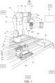
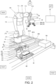
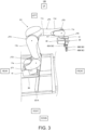
- Figs. 1 to 3 are schematic diagrams illustrating an outline configuration of a robot system 100 according to Embodiment 1.
- Fig. 1 illustrates a state where a claw member is attached to a finger member
- Fig. 2 illustrates a state where the claw member is removed from the finger member
- Fig. 3 illustrates a state seen from a different direction from Fig. 1 , and illustrates a state where a different claw member from the claw member illustrated in Fig. 1 is attached.
- a front-and-rear direction, an up-and-down direction, and a left-and-right direction of the robot system are indicated as a front-and-rear direction, an up-and-down direction, and a left-and-right direction in the drawings.
- the robot system 100 includes a robot 101, a hand 20, a control device 50, and a support member 200.
- the robot 101 is placed on a movable body 60.
- the movable body 60 is disposed on rail members 301A and 301B extending in the left-and-right direction, and it is configured to move in the left-and-right direction by a suitable actuator.
- the robot system 100 is further provided with an imaging device (for example, a camera), and image/video information which is imaged by the imaging device may be inputted into the control device 50. Further, the control device 50 may be configured to grasp the shape of a workpiece based on the acquired image/video information, and select a claw member which is adapted for the shape of the workpiece.
- an imaging device for example, a camera
- image/video information which is imaged by the imaging device may be inputted into the control device 50.
- the control device 50 may be configured to grasp the shape of a workpiece based on the acquired image/video information, and select a claw member which is adapted for the shape of the workpiece.
- a support member 200 is disposed in front of the robot 101.
- the support member 200 accommodates a plurality of kinds of pairs of claw members 41-45.
- a configuration of the support member 200 is described with reference to Figs. 1 and 4 . Note that configurations of the claw members 41-45 will be described later.
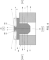
- Fig. 4 is a cross-sectional view illustrating an outline configuration of the support member 200 and the claw member 42 of the robot system 100 illustrated in Fig. 3 . Note that, in Fig. 4 , the up-and-down direction and the left-and-right direction of the robot system 100 are indicated as the up-and-down direction and the left-and-right direction in the drawing.
- the support member 200 includes a first support member 201 and a second support member 202 which extend in the left-and-right direction, and a space between the first support member 201 and the second support member 202 constitutes a recess 203.
- the recess 203 is configured so that each of tip-end parts 71 of the claw members 41-45 is inserted therein. In detail, in a state where the extending direction of the claw members 41-45 is oriented in the vertical direction, each of the tip-end parts 71 of the claw members 41-45 is inserted in the recess 203.
- the support member 200 is comprised of two members, it is not limited to this configuration but it may be comprised of a single member.
- the recess 203 may be formed in an upper surface of one box-shaped member.
- various workpieces W1-W5 are disposed in front of the support member 200.
- the control device 50 or an operator selects various kinds of claw members 41-45 which suit the shapes of the various workpieces W1-W5.
- the control device 50 operates the robot 101 so that the selected claw member is attached to the finger member 30.
- the robot 101 is a vertical articulated robotic arm including a serially-coupled body of a plurality of links (here, a first link 11a to a sixth link 11f), a plurality of joints (here, a first joint JT1 to a sixth joint JT6), and a pedestal 15 which supports these parts.
- a serially-coupled body of a plurality of links here, a first link 11a to a sixth link 11f
- a plurality of joints here, a first joint JT1 to a sixth joint JT6
- a pedestal 15 which supports these parts.
- the pedestal 15 and a base-end part of the first link 11a are coupled to each other so as to be pivotable on an axis extending vertically.
- a tip-end part of the first link 11a and a base-end part of the second link 11b are coupled to each other so as to be pivotable on an axis extending horizontally.
- a tip-end part of the second link 11b and a base-end part of the third link 11c are coupled to each other so as to be pivotable on an axis extending horizontally.
- a tip-end part of the third link 11c and a base-end part of the fourth link 11d are coupled to each other so as to be pivotable on an axis extending in the longitudinal direction of the fourth link 11d.
- a tip-end part of the fourth link 11d and a base-end part of the fifth link 11e are coupled to each other so as to be pivotable on an axis perpendicular to the longitudinal direction of the fourth link 11d.
- a tip-end part of the fifth link 11e and the base-end part of the sixth link 11f are coupled to each other so as to be twistable.
- a mechanical interface 12 is provided to a tip-end part of the sixth link 11f.
- the hand 20 is detachably attached to the mechanical interface 12. Note that a configuration of the hand 20 will be described later.
- first joint JT1 to the sixth joint JT6 are each provided with a drive motor (not illustrated) as one example of an actuator which relatively rotates two members coupled to each other via the joint.
- the drive motor may be a servomotor which is servo-controlled by the control device 50, for example.
- first joint JT1 to the sixth joint JT6 are each provided with a rotation sensor which detects a rotational position of the drive motor, and a current sensor which detects current for controlling rotation of the drive motor (none of them is illustrated).
- the rotation sensor may be an encoder, for example.
- the control device 50 includes an arithmetic processor such as a microprocessor and a CPU, and a memory, such as a ROM and a RAM, (none of them is illustrated).
- the memory stores information on a basic program, various fixed data, etc.
- the arithmetic processor is configured to perform various kinds of operation of the robot system 100 by reading and executing software, such as the basic program stored in the memory.
- control device 50 may be comprised of a sole control device which carries out a centralized control, or may be comprised of a plurality of control devices which collaboratively carry out a distributed control. Further, the control device 50 may be comprised of a microcomputer, or may be comprised of an MPU, a PLC (Programmable Logic Controller), a logical circuit, etc.
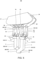
- Fig. 5 is a schematic diagram illustrating an outline configuration of the hand 20 and the claw member 41 of the robot system 100 illustrated in Fig. 1 .
- the hand 20 has a pair of finger members 30A and 30B, a main body 21, and an actuator 22.
- the actuator 22 is disposed behind the main body 21, and it is configured to operate the pair of finger members 30A and 30B so as to approach and separate to/from each other.
- the actuator 22 may be comprised of a servomotor.
- the hand 20 may have various kinds of members for making the pair of finger members 30A and 30B approach and separate to/from each other (for example, a gear set and a cam mechanism).
- a direction from a tip-end part of one of the finger members (30A) toward a tip-end part of the other finger member (30B) is referred to as a "first direction.”
- a direction illustrated by an arrow X is the first direction.
- the first direction is described as the left-and-right direction.
- the extending direction of the finger members 30A and 30B is the vertical direction (up-and-down direction).
- the claw members 41A and 41B are connected to the pair of finger members 30A and 30B, respectively. Further, in Embodiment 1, the pair of finger members 30A and 30b each have four link members 3A to 3D and a connecting member 3E.
- each one when not distinguishing the pair of finger members 30A and 30B from each other, each one may be referred to as “the finger member 30.”
- the claw members 41A and 41B when not distinguishing the claw members 41A and 41B from each other, each one may be referred to as “the claw member 41.”
- the finger member 30 has the four link members 3A to 3D, it is not limited to this configuration.
- the finger member 30 may have a sole link member, or may have two link members.
- Base-end parts of the link members 3A and 3B are each rotatably connected to the main body 21. Further, a tip-end part of the link member 3A is rotatably connected to a base-end part of the link member 3C. Similarly, a tip-end part of the link member 3B is rotatably connected to a base-end part of the link member 3D. Tip-end parts of the link members 3C and 3D are each rotatably connected to the connecting member 3E.
- the connecting member 3E provided to the tip-end part of the finger member 30 is connected to a base-end part 72 of the claw member 41.
- configurations of the connecting member 3E of the finger member 30 and the base-end part 72 of the claw member 42 are described with reference to Fig. 8 .
- Fig. 8 is a schematic diagram illustrating an outline configuration of the tip-end part of the finger member 30 and the claw member 42 of the robot system 100 illustrated in Fig. 3 . Note that, in Fig. 8 , the front-and-rear direction, the up-and-down direction, and the left-and-right direction of the robot system 100 are indicated as the front-and-rear direction, the up-and-down direction, and the left-and-right direction in the drawing.
- the connecting members 3E of the finger members 30 are each formed in a rectangular parallelepiped shape.
- a flange-shaped to-be-engaged part 61 extending in the left-and-right direction is formed.
- the to-be-engaged part 61 is formed in a tapered shape.
- the to-be-engaged part 61 on the finger member 30A side is formed in a tapered shape so that the right surface becomes smaller in the area than the left surface.
- the to-be-engaged part 61 on the finger member 30B side is formed in a tapered shape so that the left surface becomes smaller in the area than the right surface.
- a first lock mechanism 80 is provided to a right surface of the connecting member 3E on the finger member 30A side (an inner surface; a tip-end part 62 of the to-be-engaged part 61). Similarly, the first lock mechanism 80 is provided to a left surface of the connecting member 3E on the finger member 30B side (an inner surface; a tip-end part 62 of the to-be-engaged part 61). Further, a first lock mechanism 90 is provided to a first stopper part 91 (described later) of the claw member 42.
- the first lock mechanisms 80 and 90 may be any kinds of mechanisms, as long as they can stop the claw member 42 so that the claw member 42 does not fall by its own weight, when the tip-end part of the to-be-engaged part 61 is oriented downwardly.
- the first lock mechanisms 80 and 90 may be comprised of magnets, or may be comprised of ball plungers, for example.
- the claw member 42 is formed in an inverted L-shape when seen in the front-and-rear direction, and it has the base-end part 72 which extends in the left-and-right direction and a tip-end part 71 which extends in the up-and-down direction.
- a concave engaging part 81 is formed in the base-end part 72 of the claw member 42A, which opens on the left-surface side and extends in the left-and-right direction (first direction).
- the concave engaging part 81 is formed in the base-end part 72 of the claw member 42B, which opens on the right surface side and extends in the left-and-right direction.
- the engaging part 81 engages with the to-be-engaged part 61 so that the claw member 42 is attached to the finger member 30.
- the inner circumferential surface of the engaging part 81 may be formed in a tapered shape so that it fits with the to-be-engaged part 61.
- the first stopper part 91 limits movement of the finger member 30 when the tip-end part 62 of the to-be-engaged part 61 contacts the first stopper part 91. Therefore, it makes the positioning of the finger member 30 and the claw member 42 easier.
- the first lock mechanism 90 is provided to the first stopper part 91.
- the first lock mechanism 90 can collaborate with the first lock mechanism 80 to fix the claw member 42 to the finger member 30.
- Figs. 9A and 9B illustrate a situation where the claw member 42 accommodated in the support member 200 is attached to the finger member 30.
- the control device 50 operates the robot 101 to move the finger members 30A and 30B so that the claw members 42 are located between the pair of finger members 30A and 30B ( Fig. 9A ).
- the control device 50 operates the actuator 22 to bring each of the pair of finger members 30A and 30B closer to the corresponding claw member 41.
- the pair of finger members 30A and 30B are brought closer to each other.
- each engaging part 81 engages with the corresponding to-be-engaged part 61 ( Fig. 9B ). Therefore, the claw member 42 is attached to the finger member 30.
- FIGS. 5 to 7 the hand 20 to which the claw member 41 is attached is illustrated.
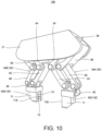
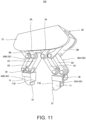
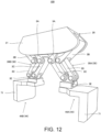
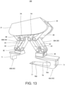
- Figs. 10 to 13 are schematic diagrams illustrating an outline configuration of the hand 20 to which another claw member is attached.
- the claw members 42-45 when distinguishing each of the pair of claw members, they are referred to as the claw members 42A-45A and 42B-45B.
- the base-end part 72 of the claw member 41 and the claw members 43-45 is configured similarly to the base-end part 72 of the claw member 42 described above, the detailed explanation is omitted.
- FIG. 5 the hand 20 to which the claw member 41 is attached is illustrated.
- Fig. 6 is a view of the claw member 41 seen from a different direction from Fig. 5 .
- each of the tip-end parts 71 of the claw members 41 is provided with a first part 85 connected from the base-end part 72, and a second part 86 which extends obliquely to the first part 85.
- the first part 85A of one claw member 41A and the first part 85B of the other claw member 41B extend in parallel to each other.
- the second part 86A of one claw member 41A and the second part 86B of the other claw member 41B intersect with each other.
- Fig. 5 the hand 20 to which the claw member 41 is attached.
- Fig. 6 is a view of the claw member 41 seen from a different direction from Fig. 5 .
- each of the tip-end parts 71 of the claw members 41 is provided with a first part 85 connected from the base-end part 72, and a second part 86 which extends
- the second part 86A of one claw member 41A has a slit 88 at the center in the thickness direction (the width direction of the mutually-opposing surfaces of the pair of tip-end parts 71), which extends from the tip end toward the root side.
- the second part 86B of the other claw member 41B penetrates the slit 88 so that the second part 86A of one claw member 41A and the second part 86B of the other claw member 41B intersect with each other.
- Each tip-end part 71 is provided with a contact surface 87 perpendicular to the first direction X.
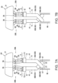
- Figs. 7A and 7B a situation where the robot system 100 holds a cylindrical workpiece W1 is illustrated.
- the control device 50 operates the robot 101 to insert the tip-end part 71 of each claw member 41 into the cylindrical workpiece W1.
- Fig. 7A illustrates a state where the tip-end part 71 is inserted into the workpiece W1.
- the control device 50 operates the actuator 22 to move the finger members 30 so that the tip-end parts of the pair of finger members 30 approach each other in the first direction X.
- an arrow Y1 and an arrow Y2 indicate the moving directions of the tip-end parts of the finger members 30.
- the directions Y1 and Y2 are also the moving directions of the base-end parts 72 of the claw members 41.
- the moving directions Y1 and Y2 of the tip-end parts of the finger members 30 are parallel to the first direction X.
- the moving direction of the tip-end part of the finger member 30 does not include any components other than the component in the first direction X.
- an arrow Z1 and an arrow Z2 indicate the moving directions of the tip ends of the tip-end parts 71 of the claw members 41. Since the second part 86A of one claw member 41A and the second part 86B of the other claw member 41B intersect with each other as described above, the tip ends of the tip-end parts 71 of the claw members 41 move in a direction separating from each other, when the base-end parts 72 of the claw members 41 move in a direction approaching each other. The tip end of the tip-end part 71 of the claw member 41 moves in parallel with the first direction X. Therefore, the contact surface 87 of each tip-end part 71 contacts the inner circumferential surface of the workpiece W1. In Fig.
- the robot system 100 holds the cylindrical workpiece W1 from the inner circumferential surface side.
- the robot system 100 can hold an annular workpiece W2 from the inner circumferential surface side.
- the control device 50 When the robot system 100 releases the cylindrical workpiece W1, the control device 50 operates the actuator 22 to operate the finger members 30 so that the tip-end parts of the pair of finger members 30 separate from each other in the first direction X.
- the tip ends of the tip-end parts 71 of the claw members 41 move in the direction approaching each other.
- the contact surface 87 of each tip-end part 71 separates from the inner circumferential surface of the workpiece W1. Therefore, the cylindrical workpiece W1 is released from the robot system 100.
- the claw member 42 has a recess 73 which is formed in an inner surface 71B of the tip-end part 71 so as to extend in the up-and-down direction.
- a plurality of grooves 74 are formed in the recess 73.
- a V-shaped (or a U-shaped) notch 75 is formed in the inner surface 71B of the tip-end part 71.
- a bar-shaped workpiece W3 such as a wrench
- the tip-end part 71 of the claw member 44 is formed in an inverted L-shape. Therefore, it can easily hold a box-shaped workpiece W4, such as a cardboard box (see Figs. 1 and 2 ).
- the tip-end part 71 of the claw member 45A is formed in a U-shape.
- the tip-end part 71 of the claw member 45A has a pair of foot parts 76A and 76B.
- the foot part 76B located below is configured so that its upper surface inclines in a plurality of steps (here, two steps), and the inclination angle of a tip-end part 77 becomes larger than the inclination angle of a base-end part 78.
- the tip-end part 71 of the claw member 45B is formed in an inverted L-shape. Therefore, it can easily hold a plate-like workpiece W5, such as a notebook (see Figs. 1 and 2 ).
- the tip-end part 77 of the foot part 76B of the claw member 45A is larger than the inclination angle of the base-end part 78, the tip-end part 77 can easily enter between a lower surface of the workpiece W5 and a floor surface. Further, when placing the held workpiece W5 on the floor surface etc., since the inclination angle of the tip-end part 77 is large, it can drop the workpiece W5 directly below, and can place the workpiece W5 correctly.
- Fig. 14 is a flowchart illustrating one example of operation of the robot system 100 according to Embodiment 1.
- the control device 50 operates the robot 101 to move the finger members 30 to given positions. That is, the control device 50 operates the finger members 30 via the robot 101.
- the control device 50 operates the actuator 22 to bring the pair of finger members 30 closer or farther to/from each other. That is, the control device 50 operates the pair of finger members 30 so that they approach or separate to/from each other via the actuator 22.
- Each processing described in Fig. 14 is realized by the control device 50 operating the finger members 30.
- the robot system 100 is configured to perform a conveying work in which it conveys the workpiece W4, and then conveys the workpieces W1 to W3 and W5, which are disposed inside the workpiece W4, to the outside of the workpiece W4. Further, the robot system 100 is configured to perform a conveying work in which it conveys the workpieces W1 to W3 and W5, which are disposed outside the workpiece W4, into the workpiece W4, and conveys the workpiece W4.
- the operator may give an instruction about which workpiece is to be held and conveyed, to the control device 50 by using the operation terminal. Further, based on the image/video information acquired from the imaging device (not illustrated), the control device 50 may grasp the shape of the workpiece and select the claw member which is adapted for (optimal to) the shape of the workpiece.
- the control device 50 operates the robot 101 so that the pair of finger members 30A and 30B are located above the claw members 41 (Step S101).
- the control device 50 operates the actuator 22 so that the pair of finger members 30A and 30B separate from each other (Step S102).
- the control device 50 operates the robot 101 so that the claw members 41 are located between the pair of finger members 30A and 30B (Step S 103).
- the control device 50 operates the robot 101 so that the tip-end part 62 of the to-be-engaged part 61 of the finger member 30 opposes to an opening of the engaging part 81 of the claw member 41.
- a state of the finger member 30 and the claw member 41 at this time corresponds to the state of Fig. 9A described above which is described using the claw member 42.
- the control device 50 operates the actuator 22 so that the pair of finger members 30A and 30B approach each other (Step S104).
- the tip ends of the pair of finger members 30A and 30B approach the corresponding claw members 41.
- the to-be-engaged part 61 of the finger member 30 engages with the engaging part 81 of the claw member 41 so that the claw member 41 is attached to the finger member 30.
- a state of the finger member 30 and the claw member 41 at this time corresponds to the state of Fig. 9B described above which is described using the claw member 42.
- the movement of the finger member 30 is limited by the tip-end part 62 of the to-be-engaged part 61 contacting the first stopper part 91. Therefore, it makes the positioning of the finger member 30 and the claw member 42 easier. Further, as the first lock mechanism 90 contacts the first lock mechanism 80, the claw member 42 is fixed to the finger member 30.
- control device 50 operates the actuator 22 and/or the robot 101 so that it holds and conveys the workpiece W1 (Step S105).
- control device 50 makes the robot 101 perform an operation for releasing the claw members 41 so that it can hold and convey a workpiece different from the workpiece W1 (for example, the workpiece W2).
- the control device 50 operates the robot 101 so that the pair of claw members 41A and 41B are located above the support member 200 (Step S106).
- control device 50 operates the actuator 22 so that the pair of finger members 30A and 30B approach each other (Step S 107). Therefore, the pair of claw members 41A and 41B can approach each other, and can be located above the opening of the recess 203 of the support member 200.
- control device 50 operates the robot 101 so that the tip-end parts 71 of the claw members 41 are located inside the recess 203 of the support member 200 (Step S108).
- control device 50 operates the robot 101 so that the claw members 41 is moved downwardly and is inserted into the recess 203.
- control device 50 operates the actuator 22 so that the pair of finger members 30A and 30B separate from each other (Step S109), and then ends this program.
- the pair of claw members 41A and 41B move so as to separate from each other according to the pair of finger members 30A and 30B, the pair of claw members 41A and 41B become impossible to move in the separating direction by side surfaces 79A outside of the tip-end parts 71 of the claw members 41A and 41B contacting an inner surface 204 of the first support member 201 or an inner surface 204 of the second support member 202, respectively.
- the pair of finger members 30A and 30B can release the claw members 41, and the claw members 41 are accommodated in the support member 200.
- control device 50 when holding and conveying the workpiece different from the workpiece W1 (for example, the workpiece W2), the control device 50 again performs the processing of Steps S101 to S109.
- the concave engaging part 81 extending in the left-and-right direction (first direction) is formed in the base-end part 72 of the claw members 41-46. Further, the flange-shaped to-be-engaged part 61 extending in the left-and-right direction (first direction) is formed in the tip-end part of the finger member 30.
- the claw members 41 can be easily attached to the finger members 30 by the control device 50 moving the robot 101 so that the claw members 41 are located between the pair of finger members 30A and 30B, and then operating the actuator 22 so that the pair of finger members 30A and 30B approach each other.
- the bottom surface of the recess which constitutes the engaging part 81 constitutes the first stopper part 91. Therefore, when attaching one of the claw members 41-46 to the finger member 30, the movement of the finger member 30 is limited by the tip-end part 62 of the to-be-engaged part 61 contacting the first stopper part 91. Therefore, it makes the positioning of the finger member 30 and the claw member easier.
- the first stopper part 91 of the claw member is provided with the first lock mechanism 90
- the tip-end part 62 of the to-be-engaged part 61 of the finger member 30 is provided with the first lock mechanism 80.
- the first lock mechanism 90 and the first lock mechanism 80 can jointly fix the claw member 42 to the finger member 30.
- the first lock mechanism 80 and the first lock mechanism 90 prevent that the claw members 41 fall out from the finger members 30.
- the pair of claw members 41A and 41B are located so that they are lined up vertically.
- one claw member 41A located above moves downwardly by its own weight, it will contact the other claw member 41B located below. Therefore, the downward movement of one claw member 41A can be suppressed, and it is prevented that the claw member 41A falls out from the finger member 30A.
- the pair of claw members 41A and 41B are configured so that their tip-end parts 71 separate from each other, when they move in parallel with the first direction so that the pair of finger members 30A and 30B approach each other.
- the tip-end part 71 of the claw member 41A and the tip-end part 71 of the claw member 41B are configured to intersect with each other on the way.
- the robot system 100 includes the hand 20 provided with the pair of finger members 30 and the actuator 22 which operates the pair of finger members 30 so that their tip-end parts approach or separate to/from each other, the control device 50, and the pair of claw members 41 each configured to be attachable and detachable to/from the corresponding finger member 30.
- the base-end part 72 of each claw member 41 is provided with the engaging part 81
- the tip-end part of each finger member 30 is provided with the to-be-engaged part 61 which may engage with the engaging part 81.
- the engaging part 81 has a concave shape extending in a direction from the tip-end part of one finger member 30 to the tip-end part of the other finger member 30.
- the control device 50 operates the finger members 30 so that the pair of claw members 41 are located between the pair of finger members 30, and then operates them so that each of the pair of finger members 30 is brought closer to the corresponding claw member 41 to engage the to-be-engaged part 61 with the engaging part 81.
- the control device 50 operates the finger members 30 so that the pair of finger members 30 approach each other to engage the to-be-engaged part 61 with the engaging part 81.
- the robot system 100 according to Embodiment 1 may further include the support member 200 which accommodates the claw members 41 in the state where the extending direction of the claw members 41 is oriented in the vertical direction, when the claw members 41 are not attached to the finger member 30.
- the support member 200 may be provided with the recess 203, and the tip-end part 71 of the claw member 41 may be inserted in the recess 203 of the support member 200.
- the to-be-engaged part 61 may be formed in a tapered shape.
- the first stopper part 91 may be provided to the claw member 41 so that it opposes to the tip end of the to-be-engaged part 61 of the finger member 30.
- the first lock mechanism may be provided to each of the first stopper part 91 of the claw member 41 and the tip-end part of the to-be-engaged part 61 of the finger member 30.
- the plurality of kinds of pairs of claw members may be accommodated in the support member 200 so that they are lined up in a third direction.
- the actuator 22 may be configured to operate at least one of the pair of finger members 30.
- the method of operating the robot system 100 according to Embodiment 1 includes the hand 20 provided with the pair of finger members 30 and the actuator 22 which operates the finger members 30 so that the tip-end parts of the pair of finger members 30 approach or separate to/from each other, the control device 50, and the pair of claw members 41 each configured to be attachable and detachable to/from the corresponding finger member 30.
- the base-end part 72 of each claw member 41 is provided with the engaging part 81
- the tip-end part of each finger member 30 is provided with the to-be-engaged part 61 which may engage with the engaging part 81.
- the engaging part 81 has a concave shape extending in the direction from the tip-end part of one finger member 30 to the tip-end part of the other finger member 30.
- the method operates the finger members 30 so that the pair of claw members 41 are located between the pair of finger members 30, and then operates them so that the pair of finger members 30 approach each other to engage the to-be-engaged part 61 with the engaging part 81.
- the method of operating the robot system 100 according to Embodiment 1 may further include the support member 200 which accommodates the claw members 41 in the state where the extending direction of the claw members 41 is oriented in the vertical direction, when the claw members 41 are not attached to the finger member 30.
- the support member 200 may be provided with the recess 203, and the tip-end part 71 of the claw member 41 may be inserted in the recess 203 of the support member 200.
- the to-be-engaged part 61 may be formed in a tapered shape.
- the claw members 41A and 41B may be provided with the first stopper part 91 so that it opposes to the tip ends of the to-be-engaged parts 61 of the finger members 30A and 30B.
- the first stopper part 91 of the claw member 41A or 41B, and the tip-end part of the to-be-engaged part 61 of the finger member 30A or 30B may be provided with the first lock mechanism.
- Fig. 15 is a schematic diagram illustrating an outline configuration of the hand 20 and the claw member 42 of the robot system 100 of Modification 1 of Embodiment 1.
- the robot system 100 of Modification 1 of Embodiment 1 is the same in the fundamental configuration as the robot system 100 according to Embodiment 1, but it differs in that at least one of the pair of finger members 30 operates.
- the actuator 22 is configured to operate at least one finger member 30 among the pair of finger members 30A and 30B.
- the actuator 22 may be configured to operate only the finger member 30A.
- the finger member 30B may be fixed to the main body 21 of the hand 20.
- the actuator 22 may be configured to operate only the finger member 30B.
- the finger member 30A may be fixed to the main body 21 of the hand 20.
- the actuator 22 may be configured to operate both of the pair of finger members 30A and 30B.
- the robot system 100 of Modification 1 configured in this way also provides similar operation and effects to the robot system 100 according to Embodiment 1.
- the actuator 22 is configured to operate at least one of the pair of finger members 30.
- the other of the pair of finger members 30 may be fixed to the main body 21 of the hand 20.
- the actuator 22 is configured to operate at least one of the pair of finger members 30.
- the other of the pair of finger members 30 may be fixed to the main body 21 of the hand 20.
- Fig. 16 is a schematic diagram illustrating an outline configuration of the finger member 30 and the claw member 42 of the robot system 100 according to Embodiment 2.
- the robot system 100 according to Embodiment 2 is similar in the fundamental configuration to the robot system 100 according to Embodiment 1, but it differs in that a concave to-be-engaged part 181 extending in the first direction is formed in the tip-end part (connecting member 3E) of the finger member 30, and in that an engaging part 161 is formed in the base-end part 72 of the claw member 42.
- the base-end part 72 of the claw member 42 is formed in a rectangular parallelepiped shape.
- the flange-shaped engaging part 161 extending in the left-and-right direction is formed in each of an upper-end part of a front surface and an upper-end part of a rear surface of the base-end part 72.
- the engaging part 161 is formed in a tapered shape.
- the engaging part 161 on the claw member 42A side is formed in the tapered shape so that the left surface becomes smaller in the area than the right surface.
- the engaging part 161 on the claw member 42B side is formed in the tapered shape so that the right surface becomes smaller in the area than the left surface.
- a first lock mechanism 180 is provided to the left surface of the base-end part 72 on the claw member 42A side (an outer surface; a tip-end part 162 of the engaging part 161). Similarly, the first lock mechanism 180 is provided to the right surface of the base-end part 72 on the claw member 42B side (an outer surface; a tip-end part 162 of the engaging part 161). Moreover, as will be described later, a first lock mechanism 190 is provided to a first stopper part 191 of the finger member 30.
- the first lock mechanisms 180 and 190 may be in any kind of forms, as long as they can stop the claw member 42 so that the claw member 42 does not fall by its own weight, when the tip-end part 162 of to-be-engaged part 181 is oriented downwardly.
- Each of the first lock mechanisms 180 and 190 may be comprised of a magnet, or may be comprised of a ball plunger, for example.
- the connecting member 3E of the finger member 30 is formed in an inverted T-shape when seen in the left-and-right direction, and has a lower-end part 31.
- the concave to-be-engaged part 181 is formed in the lower-end part 31 of the finger member 30A, which opens on the right surface side and extends in the left-and-right direction (first direction).
- the concave to-be-engaged part 181 is formed in the lower-end part 31 of the finger member 30B, which opens on the left-surface side and extends in the left-and-right direction.
- the to-be-engaged part 181 engages with the engaging part 161 so that the claw member 42 is attached to the finger member 30.
- the inner circumferential surface of the to-be-engaged part 181 may be formed in a tapered shape so that it fits to the engaging part 161.
- the bottom surface of the recess which constitutes the to-be-engaged part 181 constitutes the first stopper part 191.
- the first stopper part 191 limits the movement of the finger member 30 by the tip-end part 162 of the engaging part 161 contacting the first stopper part 191. Therefore, it makes the positioning of the finger member 30 and the claw member 42 easier.
- first stopper part 191 is provided with the first lock mechanism 190.
- the first lock mechanism 190 can fix the claw member 42 to the finger member 30 in collaboration with the first lock mechanism 180.
- the robot system 100 according to Embodiment 2 configured in this way also provides similar operation and effects to the robot system 100 according to Embodiment 1.
- the actuator 22 operates the pair of finger members 30A and 30B so that the pair of finger members 30A and 30B approach/separate to/from each other similarly to the robot system 100 according to Embodiment 1, it is not limited to this configuration.
- At least one finger member 30 among the pair of finger members 30A and 30B may be operated by the actuator.
- the other finger member 30 may be fixed to the main body 21 of the hand 20.
- the robot system 100 includes the hand 20 provided with the pair of finger members 30 and the actuator 22 which operates the pair of finger members 30 so that the tip-end parts of the pair of finger members 30 approach or separate to/from each other, the control device 50, and the pair of claw members 42 each configured to be attachable and detachable to/from the corresponding finger member 30.
- the base-end part 72 of each claw member 42 is provided with the engaging part 161
- the tip-end part of each finger member 30 is provided with the to-be-engaged part 181 which may engage with the engaging part 161.
- the to-be-engaged part 181 has a concave shape extending in the direction from the tip-end part of one finger member 30 to the tip-end part of the other finger member 30.
- the control device 50 operates the finger members 30 so that the pair of claw members 42 are located between the pair of finger members 30, and then operates them so that the pair of finger members 30 approach each other to engage the to-be-engaged part 181 with the engaging part 161.
- the engaging part 161 may be formed in a tapered shape.
- the finger member 30 may be provided with a second stopper part so that it opposes to the tip end of the engaging part 161 of the claw member 42.
- the second stopper part of the finger member 30 and the tip-end part of the engaging part 161 of the claw member 42 may be each provided with a second lock mechanism.
- the robot system 100 according to Embodiment 2 may further be provided with the support member 200 which accommodates the claw members 42 in the state where the extending direction of the claw members 42 is oriented in the vertical direction, when the claw members 42 are not attached to the finger members 30.
- the support member 200 may be provided with the recess 203, and the tip-end parts 71 of the claw members 42 may be inserted in the recess 203 of the support member 200.
- the plurality of kinds of pairs of claw members 42 may be accommodated in the support member 200 so that they are lined up.
- the actuator may be configured to operate at least one of the pair of finger members 30.
- the other of the pair of finger members 30 may be fixed to the main body 21 of the main body 21 of the hand 20.
- the method of operating the robot according to Embodiment 2 includes the hand 20 provided with the pair of finger members 30 and the actuator 22 which operates the pair of finger members 30 so that the tip-end parts of the pair of finger members 30 approach or separate to/from each other, the control device 50, and the pair of claw members 42 each configured to be attachable and detachable to/from the corresponding finger member 30.
- the base-end part 72 of each claw member 42 is provided with the engaging part 161.
- the tip-end part of each finger member 30 is provided with the to-be-engaged part 181 which may engage with the engaging part 161.
- the to-be-engaged part 181 has a concave shape extending in the direction from the tip-end part of one finger member 30 to the tip-end part of the other finger member 30.
- the method operates the finger members 30 so that the pair of claw members 42 are located between the pair of finger members 30, and then operates them so that the pair of finger members 30 approach each other to engage the to-be-engaged part 181 with the engaging part 16
- the claw member 42 does not fall out from the finger member 30.
- the claw members 42 are located so that they are lined up vertically.
- the claw member 42 located above moves downwardly by its own weight, it will contact the other claw member 42 located below. Therefore, the downward movement of one claw member 42 can be suppressed, and it is prevented that the claw member 42 falls out from the finger member 30.
- the engaging part 161 may be formed in a tapered shape.
- the method of operating the robot according to Embodiment 2 may further be provided with the support member 200 which accommodates the claw members 42 in the state where the extending direction of the claw members 42 is oriented in the vertical direction, when the claw members 42 are not attached to the finger members 30.
- the support member 200 may be provided with the recess 203.
- the tip-end parts 71 of the claw members 42 may be inserted in the recess 203 of the support member 200.
- the finger member 30 may be provided with the second stopper part so that it opposes to the tip end of the engaging part 161 of the claw member 42.
- the second stopper part of the finger member 30, and the tip-end part of the engaging part 161 of the claw member 42 may be each provided with the second lock mechanism.
- the plurality of kinds of pairs of claw members 42 may be accommodated in the support member 200 so that they are lined up.
- the actuator may be configured to operate at least one of the pair of finger members 30.
- the other of the pair of finger members 30 may be fixed to the main body 21 of the hand.
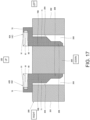
- Fig. 17 is a cross-sectional view illustrating an outline configuration of the support member 200 and the claw member 42 of the robot system 100 according to Embodiment 3.
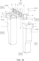
- Fig. 18 is a schematic diagram illustrating an outline configuration of the finger member 30 and the claw member 42 of the robot system 100 according to Embodiment 3. Note that, in Fig. 17 , the up-and-down direction and the left-and-right direction of the robot system 100 are indicated as the up-and-down direction and the left-and-right direction in the drawing. Further, in Fig.
- the front-and-rear direction, the up-and-down direction, and the left-and-right direction of the robot system 100 are indicated as the front-and-rear direction, the up-and-down direction, and the left-and-right direction in the drawing.
- the robot system 100 according to Embodiment 3 is similar in the fundamental configuration to the robot system 100 according to Embodiment 1, but it differs in that a pair of the recesses 203 are formed in the support member 200, and in that the claw members 42 corresponding to the pair of recesses 203 are disposed.
- the support member 200 includes the first support member 201, the second support member 202, and a third support member 205 which extend in the left-and-right direction, and the third support member 205 is disposed between the first support member 201 and the second support member 202. Further, a space between the first support member 201 and the third support member 205 and a space between the second support member 202 and the third support member 205 each constitute the recess 203.
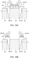
- Figs. 19A and 19B a situation where the claw members 42 accommodated in the support member 200 are attached to the finger members 30 is illustrated.
- the control device 50 operates the robot 101 to move the finger members 30A and 30B so that the pair of finger members 30A and 30B are located between the pair of claw members 42 ( Fig. 19A ).
- the control device 50 operates the actuator 22 to bring the pair of finger members 30A and 30B closer to the corresponding claw members 42.
- the pair of finger members 30A and 30B are separated from each other.
- each engaging part 81 engages with the corresponding to-be-engaged part 61 ( Fig. 19B ). Therefore, the claw members 42 are attached to the finger members 30.
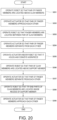
- Fig. 20 is a flowchart illustrating one example of operation of the robot system 100 according to Embodiment 3.
- the control device 50 operates the robot 101 so that the pair of finger members 30A and 30B are located above the claw members 41 (Step S201).
- the control device 50 operates the actuator 22 so that the pair of finger members 30A and 30B approach each other (Step S202).
- the control device 50 operates the robot 101 so that the pair of finger members 30A and 30B are located between the pair of claw members 42A and 42B (Step S203).
- the control device 50 operates the robot 101 so that the tip-end part 62 of the to-be-engaged part 61 of the finger member 30 opposes to the opening of the engaging part 81 of the claw member 42.
- the state of the finger member 30 and the claw member 42 at this time is illustrated in Fig. 19A described above.
- the control device 50 operates the actuator 22 so that the pair of finger members 30A and 30B separate from each other (Step S204).
- the tip ends of the pair of finger members 30A and 30B approach the corresponding claw members 42. Therefore, the to-be-engaged part 61 of the finger member 30 engages with the engaging part 81 of the claw member 41 so that the claw member 41 is attached to the finger member 30.
- the state of the finger member 30 and the claw member 42 at this time is illustrated in Fig. 19B described above.
- the movement of the finger member 30 is limited by the tip-end part 62 of the to-be-engaged part 61 contacting the first stopper part 91. Therefore, it makes the positioning of the finger member 30 and the claw member 42 easier. Further, by the first lock mechanism 80 contacting the first lock mechanism 90, the claw member 42 is fixed to the finger member 30.
- the control device 50 operates the actuator 22 and/or the robot 101 so that it holds and conveys a workpiece (Step S205).
- a cylindrical or tubular member such as the workpiece W1 illustrated in Fig. 1 etc., is assumed, for example. That is, the robot 101 according to Embodiment 3 is configured to hold the workpiece from the inner circumferential surface side.
- control device 50 makes the robot 101 perform operation for releasing the claw members 42.
- control device 50 operates the robot 101 so that the pair of claw members 42A and 42B are located above the support member 200 (Step S206).
- control device 50 operates the actuator 22 so that the pair of finger members 30A and 30B separate from each other (Step S207). Therefore, the tip-end parts of the pair of claw members 42A and 42B can be located above the opening of the recesses 203 of the support member 200.
- control device 50 operates the robot 101 so that the tip-end parts 71 of the claw members 42 are located in the recess 203 of the support member 200 (Step S208).
- control device 50 operates the robot 101 so that the claw members 42 are moved downwardly and are inserted into the recess 203.
- control device 50 operates the actuator 22 so that the pair of finger members 30A and 30B approach each other (Step S209), and then ends this program.
- the pair of claw members 42A and 42B move so that they approach each other according to the pair of finger members 30A and 30B, they become impossible to move in the approaching direction by the side surfaces 79B inside the tip-end parts 71 of the claw members 42A and 42B contacting the side surfaces 206 of the third support member 205.
- the pair of finger members 30A and 30B can release the claw members 42, and the claw members 42 are accommodated in the support member 200.
- the robot system 100 according to Embodiment 3 configured in this way also provides similar operation and effects to the robot system 100 according to Embodiment 1.
- the actuator 22 operates the pair of finger members 30A and 30B so that the pair of finger members 30A and 30B approach and separate to/from each other similarly to the robot system 100 according to Embodiment 1, it is not limited to this configuration.
- At least one of the pair of finger members 30A and 30B may be operated by the actuator 22.
- the other of the finger members 30A and 30B may be fixed to the main body 21 of the hand 20.
- the robot system 100 includes the hand 20 provided with the pair of finger members 30 and the actuator 22 which operates the pair of finger members 30 so that the tip-end parts of the pair of finger members 30 approach or separate to/from each other, the control device 50, and the pair of claw members 42 each configured to be attachable and detachable to/from the corresponding finger member 30.
- the base-end part 72 of each claw member 42 is provided with the engaging part 81
- the tip-end part of each finger member 30 is provided with the to-be-engaged part 61 which may engage with the engaging part 81.
- the engaging part 81 has a concave shape extending in the direction from the tip-end part of one finger member 30 to the tip-end part of the other finger member 30.
- the control device 50 operates the finger members 30 so that the pair of finger members 30 are located between the pair of claw members 42, and then operates them so that each of the pair of finger members 30 is brought closer to the corresponding claw member 42 to engage the to-be-engaged part 61 with the engaging part 81.
- the control device 50 operates the pair of finger members 30 so that the pair of finger members 30 separate from each other to engage the to-be-engaged part 61 with the engaging part 81.
- the robot system 100 according to Embodiment 3 may further be provided with the support member 200 which accommodates the claw members 42 in the state where the extending direction of the claw members 42 is oriented in the vertical direction, when the claw members 42 are not attached to the finger members 30.
- the support member 200 may be provided with the recess 203, and the tip-end parts 71 of the claw members 42 may be inserted in the recess 203 of the support member 200.
- the to-be-engaged part 61 may be formed in a tapered shape.
- the claw member 42 may be provided with the first stopper part so that it opposes to the tip end of the to-be-engaged part 61 of the finger member 30.
- the first stopper part of the claw member 42 and the tip-end part of the to-be-engaged part 61 of the finger member 30 may be each provided with the first lock mechanism.
- the actuator may be configured to operate at least one of the pair of finger members 30.
- the other of the pair of finger members 30 may be fixed to the main body 21 of the hand 20.
- the method of operating the robot system 100 according to Embodiment 3 includes the hand 20 provided with the pair of finger members 30 and the actuator 22 which operates the pair of finger members 30 so that the tip-end parts of the pair of finger members 30 approach or separate to/from each other, the control device 50, and the pair of claw members 42 each configured to be attachable and detachable to/from the corresponding finger member 30.
- the base-end part 72 of each claw member 42 is provided with the engaging part 81.
- the tip-end part of each finger member 30 is provided with the to-be-engaged part 61 which may engage with the engaging part 81.
- the engaging part 81 has a concave shape extending in the direction from the tip-end part of one finger member 30 to the tip-end part of the other finger member 30.
- the method operates the finger members 30 so that the pair of finger members 30 are located between the pair of claw members 42, and then operates them so that the pair of finger members 30 separate from each other to engage the to-be-engaged part 61 with the engaging part
- the method of operating the robot system 100 according to Embodiment 3 may further be provided with the support member 200 which accommodates the claw members 42 in the state where the extending direction of the claw members 42 is oriented in the vertical direction, when the claw members 42 are not attached to the finger members 30.
- the support member 200 may be provided with the recess 203, and the tip-end parts 71 of the claw members 42 may be inserted in the recess 203 of the support member 200.
- the to-be-engaged part 61 may be formed in a tapered shape.
- the claw members 41A and 41B may be provided with the first stopper parts 91 so that they oppose to the tip ends of the to-be-engaged parts 61 of the finger members 30A and 30B.
- the first stopper part 91 of the claw members 41A and 41B, and the tip-end part of the to-be-engaged part 61 of the finger members 30A and 30B may be each provided with the first lock mechanism.
- Fig. 21 is a schematic diagram illustrating an outline configuration of the finger member 30 and the claw member 42 of the robot system 100 according to Embodiment 4.
- the robot system 100 according to Embodiment 4 is similar in the fundamental configuration to the robot system 100 according to Embodiment 3, but it differs in that a concave to-be-engaged part 181 extending in the first direction is formed in the tip-end part (connecting member 3E) of the finger member 30, and in that the engaging part 161 is formed in the base-end part 72 of the claw member 42.
- the base-end part 72 of the claw member 42 is formed in a rectangular parallelepiped shape.
- the flange-shaped engaging part 161 extending in the left-and-right direction is formed in each of the upper-end part of the front surface and the upper-end part of the rear surface of the base-end part 72.
- the engaging part 161 is formed in a tapered shape.
- the engaging part 161 on the claw member 42A side is formed in the tapered shape so that the right surface becomes smaller in the area than the left surface.
- the engaging part 161 on the claw member 42B side is formed in the tapered shape so that the left surface becomes smaller in the area than the right surface.
- the right surface of the base-end part 72 on the claw member 42A side (an inner surface; the tip-end part 162 of the engaging part 161) is provided with the first lock mechanism 180.
- the left surface of the base-end part 72 on the claw member 42B side (an inner surface; the tip-end part 162 of the engaging part 161) is provided with the first lock mechanism 180.
- the first stopper part 191 of the finger member 30 is provided with the first lock mechanism 190.
- the first lock mechanisms 180 and 190 may be in any kind of forms, as long as they can stop the claw member 42 so that the claw member 42 does not fall by its own weight when the tip-end part 162 of the engaging part 161 is oriented downwardly.
- the first lock mechanisms 180 and 190 may be comprised of magnets, or may be comprised of ball plungers, for example.
- the connecting member 3E of the finger member 30 is formed in an inverted T-shape when seen in the left-and-right direction, and has the lower-end part 31.
- the concave to-be-engaged part 181 which opens on the left-surface side and extends in the left-and-right direction (first direction) is formed in the lower-end part 31 of the finger member 30A.
- the concave to-be-engaged part 181 which opens on the right-and-left surface sides and extends in the left-and-right direction is formed in the lower-end part 31 of the finger member 30B.
- the to-be-engaged part 181 engages with the engaging part 161 so that the claw member 42 is attached to the finger member 30.
- the inner circumferential surface of the to-be-engaged part 181 may be formed in a tapered shape so that it fits with the engaging part 161.
- the bottom surface of the recess which constitutes the to-be-engaged part 181 constitutes the first stopper part 191.
- the first stopper part 191 limits the movement of the finger member 30 by contacting the tip-end part 162 of the engaging part 161. Therefore, it makes the positioning of the finger member 30 and the claw member 42 easier.
- first stopper part 191 is provided with the first lock mechanism 190.
- the first lock mechanism 190 can fix the claw member 42 to the finger member 30 in collaboration with the first lock mechanism 180.
- the robot system 100 according to Embodiment 4 configured in this way also provides similar operation and effects to the robot system 100 according to Embodiment 3.
- the actuator 22 operates the pair of finger members 30 so that the pair of finger members 30A and 30B approach and separate to/from each other, similarly to the robot system 100 according to Embodiment 1, it is not limited to this configuration.
- At least one of the pair of finger members 30A and 30B may be operated by the actuator 22.
- the other finger member 30 may be fixed to the main body 21 of the hand 20.
- the robot system 100 includes the hand 20 provided with the pair of finger members 30 and the actuator 22 which operates the pair of finger members 30 so that the tip-end parts of the pair of finger members 30 approach or separate to/from each other, the control device 50, and the pair of claw members 42 each configured to be attachable and detachable to/from the corresponding finger member 30.
- the base-end part 72 of each claw member 42 is provided with the engaging part 161
- the tip-end part of each finger member 30 is provided with the to-be-engaged part 181 which may engage with the engaging part 161.
- the to-be-engaged part 181 has a concave shape extending in the direction from the tip-end part of one finger member 30 to the tip-end part of the other finger member 30.
- the control device 50 operates the finger members 30 so that the pair of finger members 30 are located between the pair of claw members 42, and then operates them so that each of the pair of finger members 30 is brought closer to the corresponding claw member 42 to engage the to-be-engaged part 181 with the engaging part 161.
- the control device 50 operates the pair of finger members 30 so that the pair of finger members 30 separate from each other to engage the to-be-engaged part 181 with the engaging part 161.
- the robot system 100 according to Embodiment 4 may further be provided with the support member 200 which accommodates the claw members 42 in the state where the extending direction of the claw members 42 is oriented in the vertical direction, when the claw members 42 are not attached to the finger members 30.
- the support member 200 may be provided with the recess 203, and the tip-end parts 71 of the claw members 42 may be inserted in the recess 203 of the support member 200.
- the engaging part 161 may be formed in a tapered shape.
- the finger member 30 may be provided with the second stopper part so that it opposes to the tip end of the engaging part 161 of the claw member 42.
- the second stopper part of the finger member 30 and the tip-end part of the engaging part 161 of the claw member 42 may be each provided with the second lock mechanism.
- the actuator may be configured to operate at least one of the pair of finger members 30.
- the other of the pair of finger members 30 may be fixed to the main body 21 of the hand 20.
- the method of operating the robot system 100 according to Embodiment 4 includes the hand 20 provided with the pair of finger members 30 and the actuator 22 which operates the pair of finger members 30 so that the tip-end parts of the pair of finger members 30 approach or separate to/from each other, the control device 50, and the pair of claw members 42 each configured to be attachable and detachable to/from the corresponding finger member 30.
- the base-end part 72 of each claw member 42 is provided with the engaging part 161.
- the tip-end part of each finger member 30 is provided with the to-be-engaged part 181 which may engage with the engaging part 161.
- the to-be-engaged part 181 has a concave shape extending in the direction from the tip-end part of one finger member 30 to the tip-end part of the other finger member 30.
- the method operates the finger members 30 so that the pair of finger members 30 are located between the pair of claw members 42, and then operates them so that the pair of finger members 30 separate from each other to engage the to-be-engaged part 181 with
- the method of operating the robot system 100 according to Embodiment 4 may further be provided with the support member 200 which accommodates the claw members 42 in the state where the extending direction of the claw members 42 is oriented in the vertical direction when the claw members 42 are not attached to the finger members 30.
- the support member 200 may be provided with the recess 203, and the tip-end parts 71 of the claw members 42 may be inserted in the recess 203 of the support member 200.
- the engaging part 161 may be formed in a tapered shape.
- the finger member 30 may be provided with the second stopper part so that it opposes to the tip end of the engaging part 161 of the claw member 42.
- the second stopper part of the finger member 30 and the tip-end part of the engaging part 161 of the claw member 42 may each be provided with the second lock mechanism.
- the actuator may be configured to operate at least one of the pair of finger members 30.
- the other of the pair of finger members 30 may be fixed to the main body 21 of the hand 20.
- a robot system comprising:
- control device operates the finger members so that the pair of claw members are located between the pair of finger members, and then operates the finger members so that the pair of finger members approach each other to bring each of the pair of finger members closer to the corresponding claw member.
- control device operates the finger members so that the pair of finger members are located between the pair of claw members, and then operates the finger members so that the pair of finger members separate from each other to bring each of the pair of finger members closer to the corresponding claw member.
- the robot system of item 11 wherein the hand is further provided with a main body, and the other finger member of the pair of finger members is fixed to the main body.
- a method of operating a robot system comprising:
- the method of operating the robot system of item 13, comprising the steps of:
- control device operates the finger members so that the pair of finger members are located between the pair of claw members, and then operates the finger members so that the pair of finger members separate from each other to bring each of the pair of finger members closer to the corresponding claw member.
Landscapes
- Engineering & Computer Science (AREA)
- Robotics (AREA)
- Mechanical Engineering (AREA)
- Manipulator (AREA)
Abstract
Description
- The present disclosure relates to a robot system and a method of operating the robot system.
- Gripping devices which grip and move a plurality of kinds of objects with different sizes (for example, see Patent Document 1) are known. According to a gripping device disclosed in
Patent Document 1, when a gripper is not equipped with an attachment, the gripper can grip a first kind of object, and when the gripper is equipped with the attachment, it can grip a second kind of object via the attachment. - [Patent Document 1]
JP2011-177862A - However, in the gripping device disclosed in
Patent Document 1, the attachment and the gripper are provided with a to-be-fit part and a fitting part, respectively, so that they extend in the extending direction of the attachment. Thus, when a robotic arm is operated so that the extending direction of the attachment is oriented in the vertical direction, the attachment may fall out from the gripper by its own weight. - The present disclosure is to solve the above-described conventional problem, and one purpose thereof is to provide a robot system and a method of operating the robot system in which a claw member does not fall out from a hand (finger member), even when the orientation of the hand is changed.
- A robot system according to the present disclosure includes a hand provided with a pair of finger members and an actuator which operates the pair of finger members so that tip-end parts of the pair of finger members approach or separate to/from each other, a control device, and a pair of claw members each configured to be attachable and detachable to/from the corresponding finger member. A base-end part of each of the claw members is provided with an engaging part. The tip-end part of each of the finger members is provided with a to-be-engaged part capable of engaging with the engaging part. One of the engaging part and the to-be-engaged part has a concave shape extending in a direction from the tip-end part of one of the finger members to the tip-end part of the other finger member. The control device operates the finger members so that one of the pair of finger members and the pair of claw members are located between the other pair, and then operates the finger members so that each of the pair of finger members is brought closer to the corresponding claw member to engage the to-be-engaged part with the engaging part.
- According to this configuration, the claw member does not fall out from the finger member, even when the orientation of the hand is changed. For example, when the orientation of the hand is changed so that the pair of finger members are lined up in the vertical direction, the claw members are located so that they are lined up in the vertical direction. Thus, even if one claw member located above moves downwardly by its own weight, it will contact the other claw member located below. Therefore, downward movement of one claw member can be suppressed, and it is prevented that the claw member falls out from the finger member.
- The above-described purpose, other purposes, features, and advantages of the present disclosure will be made clear by the detailed description of preferred embodiments below, with reference to accompanying drawings.
- According to the robot system and the robot system of the present disclosure, the claw member does not fall out from the finger member of the hand even when the orientation of the hand is changed.
-
-
Fig. 1 is a schematic diagram illustrating an outline configuration of a robot system according toEmbodiment 1. -
Fig. 2 is a schematic diagram illustrating an outline configuration of the robot system according toEmbodiment 1. -
Fig. 3 is a schematic diagram illustrating an outline configuration of the robot system according toEmbodiment 1. -
Fig. 4 is a cross-sectional view illustrating an outline configuration of a support member and a claw member of the robot system illustrated inFig. 3 . -
Fig. 5 is a schematic diagram illustrating an outline configuration of a hand and a claw member of the robot system illustrated inFig. 1 . -
Fig. 6 is a schematic diagram of the claw member ofFig. 5 seen in a different direction. -
Figs. 7A and 7B are schematic diagrams illustrating situations where the hand and the claw member ofFig. 5 hold a workpiece. -
Fig. 8 is a schematic diagram illustrating an outline configuration of a tip-end part of a finger member and the claw member of the robot system illustrated inFig. 3 . -
Figs. 9A and 9B are schematic diagrams illustrating situations where the claw member illustrated inFig. 4 is attached to the finger member. -
Fig. 10 is a schematic diagram illustrating an outline configuration of a hand equipped with the claw member ofFig. 8 . -
Fig. 11 is a schematic diagram illustrating an outline configuration of the hand equipped with another claw member. -
Fig. 12 is a schematic diagram illustrating an outline configuration of the hand equipped with still another claw member. -
Fig. 13 is a schematic diagram illustrating an outline configuration of the hand equipped with still another claw member. -
Fig. 14 is a flowchart illustrating one example of operation of the robot system according toEmbodiment 1. -
Fig. 15 is a schematic diagram illustrating an outline configuration of a hand and a claw member of a robot system ofModification 1 ofEmbodiment 1. -
Fig. 16 is a schematic diagram illustrating an outline configuration of a tip-end part of a finger member and a claw member of a robot system according to Embodiment 2. -
Fig. 17 is a cross-sectional view illustrating an outline configuration of a support member and a claw member of a robot system according to Embodiment 3. -
Fig. 18 is a schematic diagram illustrating an outline configuration of a tip-end part of a finger member and the claw member of the robot system according to Embodiment 3. -
Figs. 19A and 19B are schematic diagrams illustrating situations where the claw member illustrated inFig. 17 is attached to the finger member. -
Fig. 20 is a flowchart illustrating one example of operation of the robot system according to Embodiment 3. -
Fig. 21 is a schematic diagram illustrating an outline configuration of a finger member and a claw member of a robot system according to Embodiment 4. - Hereinafter, embodiments of the present disclosure will be described with reference to the drawings. Note that, throughout the drawings, the same reference characters are given to the same or corresponding parts to omit redundant explanation. Further, throughout the drawings, components for explaining the present disclosure are selectively illustrated, and illustration of other components may be omitted. Moreover, the present disclosure is not limited to the following embodiments.
- Below, one example of a robot and a robot system according to
Embodiment 1 is described with reference toFigs. 1 to 13 . -
Figs. 1 to 3 are schematic diagrams illustrating an outline configuration of arobot system 100 according toEmbodiment 1.Fig. 1 illustrates a state where a claw member is attached to a finger member, and,Fig. 2 illustrates a state where the claw member is removed from the finger member. Further,Fig. 3 illustrates a state seen from a different direction fromFig. 1 , and illustrates a state where a different claw member from the claw member illustrated inFig. 1 is attached. - Note that, in
Figs. 1 to 3 , a front-and-rear direction, an up-and-down direction, and a left-and-right direction of the robot system are indicated as a front-and-rear direction, an up-and-down direction, and a left-and-right direction in the drawings. - As illustrated in
Figs. 1 to 3 , therobot system 100 according to Embodiment 1 includes arobot 101, ahand 20, acontrol device 50, and asupport member 200. Therobot 101 is placed on amovable body 60. Themovable body 60 is disposed onrail members - Note that the
robot system 100 is further provided with an imaging device (for example, a camera), and image/video information which is imaged by the imaging device may be inputted into thecontrol device 50. Further, thecontrol device 50 may be configured to grasp the shape of a workpiece based on the acquired image/video information, and select a claw member which is adapted for the shape of the workpiece. - A
support member 200 is disposed in front of therobot 101. Thesupport member 200 accommodates a plurality of kinds of pairs of claw members 41-45. Here, a configuration of thesupport member 200 is described with reference toFigs. 1 and4 . Note that configurations of the claw members 41-45 will be described later. -
Fig. 4 is a cross-sectional view illustrating an outline configuration of thesupport member 200 and theclaw member 42 of therobot system 100 illustrated inFig. 3 . Note that, inFig. 4 , the up-and-down direction and the left-and-right direction of therobot system 100 are indicated as the up-and-down direction and the left-and-right direction in the drawing. - As illustrated in
Figs. 1 and4 , thesupport member 200 includes afirst support member 201 and asecond support member 202 which extend in the left-and-right direction, and a space between thefirst support member 201 and thesecond support member 202 constitutes arecess 203. Therecess 203 is configured so that each of tip-end parts 71 of the claw members 41-45 is inserted therein. In detail, in a state where the extending direction of the claw members 41-45 is oriented in the vertical direction, each of the tip-end parts 71 of the claw members 41-45 is inserted in therecess 203. - Note that, although in
Embodiment 1 thesupport member 200 is comprised of two members, it is not limited to this configuration but it may be comprised of a single member. In this case, therecess 203 may be formed in an upper surface of one box-shaped member. - Further, as illustrated in
Fig. 1 , various workpieces W1-W5 are disposed in front of thesupport member 200. In therobot system 100, thecontrol device 50 or an operator selects various kinds of claw members 41-45 which suit the shapes of the various workpieces W1-W5. Thecontrol device 50 operates therobot 101 so that the selected claw member is attached to thefinger member 30. - The
robot 101 is a vertical articulated robotic arm including a serially-coupled body of a plurality of links (here, afirst link 11a to asixth link 11f), a plurality of joints (here, a first joint JT1 to a sixth joint JT6), and apedestal 15 which supports these parts. Note that, although inEmbodiment 1 the vertical articulated robot is adopted as therobot 101, it is not limited to this configuration but it may adopt a horizontal articulated robot. - In the first joint JT1, the
pedestal 15 and a base-end part of thefirst link 11a are coupled to each other so as to be pivotable on an axis extending vertically. In the second joint JT2, a tip-end part of thefirst link 11a and a base-end part of thesecond link 11b are coupled to each other so as to be pivotable on an axis extending horizontally. In the third joint JT3, a tip-end part of thesecond link 11b and a base-end part of thethird link 11c are coupled to each other so as to be pivotable on an axis extending horizontally. - In the fourth joint JT4, a tip-end part of the
third link 11c and a base-end part of thefourth link 11d are coupled to each other so as to be pivotable on an axis extending in the longitudinal direction of thefourth link 11d. In the fifth joint JT5, a tip-end part of thefourth link 11d and a base-end part of thefifth link 11e are coupled to each other so as to be pivotable on an axis perpendicular to the longitudinal direction of thefourth link 11d. In the sixth joint JT6, a tip-end part of thefifth link 11e and the base-end part of thesixth link 11f are coupled to each other so as to be twistable. - A
mechanical interface 12 is provided to a tip-end part of thesixth link 11f. Thehand 20 is detachably attached to themechanical interface 12. Note that a configuration of thehand 20 will be described later. - Further, the first joint JT1 to the sixth joint JT6 are each provided with a drive motor (not illustrated) as one example of an actuator which relatively rotates two members coupled to each other via the joint. The drive motor may be a servomotor which is servo-controlled by the
control device 50, for example. Moreover, the first joint JT1 to the sixth joint JT6 are each provided with a rotation sensor which detects a rotational position of the drive motor, and a current sensor which detects current for controlling rotation of the drive motor (none of them is illustrated). The rotation sensor may be an encoder, for example. - The
control device 50 includes an arithmetic processor such as a microprocessor and a CPU, and a memory, such as a ROM and a RAM, (none of them is illustrated). The memory stores information on a basic program, various fixed data, etc. The arithmetic processor is configured to perform various kinds of operation of therobot system 100 by reading and executing software, such as the basic program stored in the memory. - Note that the
control device 50 may be comprised of a sole control device which carries out a centralized control, or may be comprised of a plurality of control devices which collaboratively carry out a distributed control. Further, thecontrol device 50 may be comprised of a microcomputer, or may be comprised of an MPU, a PLC (Programmable Logic Controller), a logical circuit, etc. - Next, configurations of the
hand 20, thefinger member 30, and the various claw members 41-45 are described with reference toFigs. 1 to 13 . -
Fig. 5 is a schematic diagram illustrating an outline configuration of thehand 20 and theclaw member 41 of therobot system 100 illustrated inFig. 1 . - As illustrated in
Figs. 1 and5 , thehand 20 has a pair offinger members main body 21, and anactuator 22. Theactuator 22 is disposed behind themain body 21, and it is configured to operate the pair offinger members actuator 22 may be comprised of a servomotor. Thehand 20 may have various kinds of members for making the pair offinger members - A direction from a tip-end part of one of the finger members (30A) toward a tip-end part of the other finger member (30B) is referred to as a "first direction." In
Fig. 5 andFigs. 7A and 7B , a direction illustrated by an arrow X is the first direction. Below, the first direction is described as the left-and-right direction. Here, the extending direction of thefinger members - The
claw members finger members Embodiment 1, the pair offinger members 30A and 30b each have fourlink members 3A to 3D and a connectingmember 3E. - Note that, when not distinguishing the pair of
finger members finger member 30." Similarly, when not distinguishing theclaw members claw member 41." - Further, although in
Embodiment 1 thefinger member 30 has the fourlink members 3A to 3D, it is not limited to this configuration. Thefinger member 30 may have a sole link member, or may have two link members. - Base-end parts of the
link members main body 21. Further, a tip-end part of thelink member 3A is rotatably connected to a base-end part of thelink member 3C. Similarly, a tip-end part of thelink member 3B is rotatably connected to a base-end part of thelink member 3D. Tip-end parts of thelink members member 3E. - The connecting
member 3E provided to the tip-end part of thefinger member 30 is connected to a base-end part 72 of theclaw member 41. Here, configurations of the connectingmember 3E of thefinger member 30 and the base-end part 72 of theclaw member 42 are described with reference toFig. 8 . - Note that, although in
Fig. 8 theclaw member 42 is illustrated, since the base-end part 72 of theclaw member 41 and the base-end part 72 of theclaw member 42 are configured similarly, the base-end part 72 of theclaw member 42 will be described below. -
Fig. 8 is a schematic diagram illustrating an outline configuration of the tip-end part of thefinger member 30 and theclaw member 42 of therobot system 100 illustrated inFig. 3 . Note that, inFig. 8 , the front-and-rear direction, the up-and-down direction, and the left-and-right direction of therobot system 100 are indicated as the front-and-rear direction, the up-and-down direction, and the left-and-right direction in the drawing. - As illustrated in
Fig. 8 , the connectingmembers 3E of thefinger members 30 are each formed in a rectangular parallelepiped shape. In each of a lower-end part on a front surface and a lower-end part on a rear surface of the connectingmember 3E, a flange-shaped to-be-engaged part 61 extending in the left-and-right direction is formed. - The to-
be-engaged part 61 is formed in a tapered shape. In detail, the to-be-engaged part 61 on thefinger member 30A side is formed in a tapered shape so that the right surface becomes smaller in the area than the left surface. Further, the to-be-engaged part 61 on thefinger member 30B side is formed in a tapered shape so that the left surface becomes smaller in the area than the right surface. - Moreover, a
first lock mechanism 80 is provided to a right surface of the connectingmember 3E on thefinger member 30A side (an inner surface; a tip-end part 62 of the to-be-engaged part 61). Similarly, thefirst lock mechanism 80 is provided to a left surface of the connectingmember 3E on thefinger member 30B side (an inner surface; a tip-end part 62 of the to-be-engaged part 61). Further, afirst lock mechanism 90 is provided to a first stopper part 91 (described later) of theclaw member 42. - The
first lock mechanisms claw member 42 so that theclaw member 42 does not fall by its own weight, when the tip-end part of the to-be-engaged part 61 is oriented downwardly. Thefirst lock mechanisms - The
claw member 42 is formed in an inverted L-shape when seen in the front-and-rear direction, and it has the base-end part 72 which extends in the left-and-right direction and a tip-end part 71 which extends in the up-and-down direction. A concave engagingpart 81 is formed in the base-end part 72 of theclaw member 42A, which opens on the left-surface side and extends in the left-and-right direction (first direction). Similarly, the concave engagingpart 81 is formed in the base-end part 72 of theclaw member 42B, which opens on the right surface side and extends in the left-and-right direction. - The engaging
part 81 engages with the to-be-engaged part 61 so that theclaw member 42 is attached to thefinger member 30. Note that the inner circumferential surface of theengaging part 81 may be formed in a tapered shape so that it fits with the to-be-engaged part 61. - Further, a bottom surface of the recess which constitutes the engaging
part 81 constitutes thefirst stopper part 91. Thefirst stopper part 91 limits movement of thefinger member 30 when the tip-end part 62 of the to-be-engaged part 61 contacts thefirst stopper part 91. Therefore, it makes the positioning of thefinger member 30 and theclaw member 42 easier. - Moreover, the
first lock mechanism 90 is provided to thefirst stopper part 91. Thefirst lock mechanism 90 can collaborate with thefirst lock mechanism 80 to fix theclaw member 42 to thefinger member 30. -
Figs. 9A and 9B illustrate a situation where theclaw member 42 accommodated in thesupport member 200 is attached to thefinger member 30. First, thecontrol device 50 operates therobot 101 to move thefinger members claw members 42 are located between the pair offinger members Fig. 9A ). Next, thecontrol device 50 operates theactuator 22 to bring each of the pair offinger members corresponding claw member 41. In this form, the pair offinger members part 81 engages with the corresponding to-be-engaged part 61 (Fig. 9B ). Therefore, theclaw member 42 is attached to thefinger member 30. - Next, a configuration of each of the various claw members 41-45 is described with reference to
Figs. 5 to 7 and10 to 13 . InFigs. 5 to 7 , thehand 20 to which theclaw member 41 is attached is illustrated.Figs. 10 to 13 are schematic diagrams illustrating an outline configuration of thehand 20 to which another claw member is attached. Note that, as for the claw members 42-45, when distinguishing each of the pair of claw members, they are referred to as theclaw members 42A-45A and 42B-45B. Further, below, since the base-end part 72 of theclaw member 41 and the claw members 43-45 is configured similarly to the base-end part 72 of theclaw member 42 described above, the detailed explanation is omitted. - In
Fig. 5 , thehand 20 to which theclaw member 41 is attached is illustrated.Fig. 6 is a view of theclaw member 41 seen from a different direction fromFig. 5 . As illustrated inFigs. 5 and6 , each of the tip-end parts 71 of theclaw members 41 is provided with afirst part 85 connected from the base-end part 72, and asecond part 86 which extends obliquely to thefirst part 85. Thefirst part 85A of oneclaw member 41A and thefirst part 85B of theother claw member 41B extend in parallel to each other. Thesecond part 86A of oneclaw member 41A and thesecond part 86B of theother claw member 41B intersect with each other. As illustrated inFig. 6 , thesecond part 86A of oneclaw member 41A has aslit 88 at the center in the thickness direction (the width direction of the mutually-opposing surfaces of the pair of tip-end parts 71), which extends from the tip end toward the root side. Thesecond part 86B of theother claw member 41B penetrates theslit 88 so that thesecond part 86A of oneclaw member 41A and thesecond part 86B of theother claw member 41B intersect with each other. Each tip-end part 71 is provided with acontact surface 87 perpendicular to the first direction X. - In
Figs. 7A and 7B , a situation where therobot system 100 holds a cylindrical workpiece W1 is illustrated. When holding the cylindrical workpiece W1, first, thecontrol device 50 operates therobot 101 to insert the tip-end part 71 of eachclaw member 41 into the cylindrical workpiece W1.Fig. 7A illustrates a state where the tip-end part 71 is inserted into the workpiece W1. - Next, the
control device 50 operates theactuator 22 to move thefinger members 30 so that the tip-end parts of the pair offinger members 30 approach each other in the first direction X. InFig. 7A , an arrow Y1 and an arrow Y2 indicate the moving directions of the tip-end parts of thefinger members 30. The directions Y1 and Y2 are also the moving directions of the base-end parts 72 of theclaw members 41. In this embodiment, the moving directions Y1 and Y2 of the tip-end parts of thefinger members 30 are parallel to the first direction X. The moving direction of the tip-end part of thefinger member 30 does not include any components other than the component in the first direction X. By adjusting inclination angles of thelink members finger member 30 moves in parallel with the first direction X, without moving up and down. - In
Fig. 7A , an arrow Z1 and an arrow Z2 indicate the moving directions of the tip ends of the tip-end parts 71 of theclaw members 41. Since thesecond part 86A of oneclaw member 41A and thesecond part 86B of theother claw member 41B intersect with each other as described above, the tip ends of the tip-end parts 71 of theclaw members 41 move in a direction separating from each other, when the base-end parts 72 of theclaw members 41 move in a direction approaching each other. The tip end of the tip-end part 71 of theclaw member 41 moves in parallel with the first direction X. Therefore, thecontact surface 87 of each tip-end part 71 contacts the inner circumferential surface of the workpiece W1. InFig. 7B , a state where thecontact surface 87 is in contact with the inner circumferential surface of the workpiece W1 is illustrated. Thus, therobot system 100 holds the cylindrical workpiece W1 from the inner circumferential surface side. Similarly, therobot system 100 can hold an annular workpiece W2 from the inner circumferential surface side. - When the
robot system 100 releases the cylindrical workpiece W1, thecontrol device 50 operates theactuator 22 to operate thefinger members 30 so that the tip-end parts of the pair offinger members 30 separate from each other in the first direction X. The tip ends of the tip-end parts 71 of theclaw members 41 move in the direction approaching each other. Thecontact surface 87 of each tip-end part 71 separates from the inner circumferential surface of the workpiece W1. Therefore, the cylindrical workpiece W1 is released from therobot system 100. - As illustrated in
Fig. 10 , theclaw member 42 has arecess 73 which is formed in aninner surface 71B of the tip-end part 71 so as to extend in the up-and-down direction. A plurality ofgrooves 74 are formed in therecess 73. Thus, the annular workpiece W2 where the peripheral surface is formed in a polygonal shape can be held easily by therecess 73 without slip (seeFigs. 1 and2 ). - As illustrated in
Fig. 11 , in theclaw member 43, a V-shaped (or a U-shaped)notch 75 is formed in theinner surface 71B of the tip-end part 71. Thus, by bringing thenotch 75 in contact with a bar-shaped workpiece W3, such as a wrench, the workpiece W3 can be held easily (seeFigs. 1 and2 ). - As illustrated in
Fig. 12 , the tip-end part 71 of theclaw member 44 is formed in an inverted L-shape. Therefore, it can easily hold a box-shaped workpiece W4, such as a cardboard box (seeFigs. 1 and2 ). - As illustrated in
Fig. 13 , the tip-end part 71 of theclaw member 45A is formed in a U-shape. In detail, the tip-end part 71 of theclaw member 45A has a pair offoot parts foot part 76B located below is configured so that its upper surface inclines in a plurality of steps (here, two steps), and the inclination angle of a tip-end part 77 becomes larger than the inclination angle of a base-end part 78. The tip-end part 71 of theclaw member 45B is formed in an inverted L-shape. Therefore, it can easily hold a plate-like workpiece W5, such as a notebook (seeFigs. 1 and2 ). In particular, since the inclination angle of the tip-end part 77 of thefoot part 76B of theclaw member 45A is larger than the inclination angle of the base-end part 78, the tip-end part 77 can easily enter between a lower surface of the workpiece W5 and a floor surface. Further, when placing the held workpiece W5 on the floor surface etc., since the inclination angle of the tip-end part 77 is large, it can drop the workpiece W5 directly below, and can place the workpiece W5 correctly. - Next, operation and effects of the
robot system 100 according toEmbodiment 1 are described in detail with reference toFigs. 1 to 14 . Note that the following operation is performed by the arithmetic processor of thecontrol device 50 reading the program stored in the memory. -
Fig. 14 is a flowchart illustrating one example of operation of therobot system 100 according toEmbodiment 1. Thecontrol device 50 operates therobot 101 to move thefinger members 30 to given positions. That is, thecontrol device 50 operates thefinger members 30 via therobot 101. Thecontrol device 50 operates theactuator 22 to bring the pair offinger members 30 closer or farther to/from each other. That is, thecontrol device 50 operates the pair offinger members 30 so that they approach or separate to/from each other via theactuator 22. Each processing described inFig. 14 is realized by thecontrol device 50 operating thefinger members 30. - First, as illustrated in
Fig. 2 , suppose that the various claw members 41-45 are not attached to the pair offinger members robot system 100 is configured to perform a conveying work in which it conveys the workpiece W4, and then conveys the workpieces W1 to W3 and W5, which are disposed inside the workpiece W4, to the outside of the workpiece W4. Further, therobot system 100 is configured to perform a conveying work in which it conveys the workpieces W1 to W3 and W5, which are disposed outside the workpiece W4, into the workpiece W4, and conveys the workpiece W4. - Then, suppose that a worker (operator) operates an operation terminal (not illustrated) to input into the
control device 50 an instruction signal for performing the conveying work to convey the workpieces W1-W5. - Note that the operator may give an instruction about which workpiece is to be held and conveyed, to the
control device 50 by using the operation terminal. Further, based on the image/video information acquired from the imaging device (not illustrated), thecontrol device 50 may grasp the shape of the workpiece and select the claw member which is adapted for (optimal to) the shape of the workpiece. - Then, as illustrated in
Fig. 14 , thecontrol device 50 operates therobot 101 so that the pair offinger members control device 50 operates theactuator 22 so that the pair offinger members - Next, the
control device 50 operates therobot 101 so that theclaw members 41 are located between the pair offinger members control device 50 operates therobot 101 so that the tip-end part 62 of the to-be-engaged part 61 of thefinger member 30 opposes to an opening of theengaging part 81 of theclaw member 41. A state of thefinger member 30 and theclaw member 41 at this time corresponds to the state ofFig. 9A described above which is described using theclaw member 42. - Next, the
control device 50 operates theactuator 22 so that the pair offinger members finger members corresponding claw members 41. Thus, the to-be-engaged part 61 of thefinger member 30 engages with the engagingpart 81 of theclaw member 41 so that theclaw member 41 is attached to thefinger member 30. A state of thefinger member 30 and theclaw member 41 at this time corresponds to the state ofFig. 9B described above which is described using theclaw member 42. - Here, the movement of the
finger member 30 is limited by the tip-end part 62 of the to-be-engaged part 61 contacting thefirst stopper part 91. Therefore, it makes the positioning of thefinger member 30 and theclaw member 42 easier. Further, as thefirst lock mechanism 90 contacts thefirst lock mechanism 80, theclaw member 42 is fixed to thefinger member 30. - Next, the
control device 50 operates theactuator 22 and/or therobot 101 so that it holds and conveys the workpiece W1 (Step S105). Next, thecontrol device 50 makes therobot 101 perform an operation for releasing theclaw members 41 so that it can hold and convey a workpiece different from the workpiece W1 (for example, the workpiece W2). In detail, thecontrol device 50 operates therobot 101 so that the pair ofclaw members - Next, the
control device 50 operates theactuator 22 so that the pair offinger members claw members recess 203 of thesupport member 200. - Next, the
control device 50 operates therobot 101 so that the tip-end parts 71 of theclaw members 41 are located inside therecess 203 of the support member 200 (Step S108). In detail, thecontrol device 50 operates therobot 101 so that theclaw members 41 is moved downwardly and is inserted into therecess 203. - Next, the
control device 50 operates theactuator 22 so that the pair offinger members - Thus, although the pair of
claw members finger members claw members side surfaces 79A outside of the tip-end parts 71 of theclaw members inner surface 204 of thefirst support member 201 or aninner surface 204 of thesecond support member 202, respectively. Thus, the pair offinger members claw members 41, and theclaw members 41 are accommodated in thesupport member 200. - Note that, when holding and conveying the workpiece different from the workpiece W1 (for example, the workpiece W2), the
control device 50 again performs the processing of Steps S101 to S109. - In the
robot system 100 according toEmbodiment 1 configured in this way, the concave engagingpart 81 extending in the left-and-right direction (first direction) is formed in the base-end part 72 of the claw members 41-46. Further, the flange-shaped to-be-engaged part 61 extending in the left-and-right direction (first direction) is formed in the tip-end part of thefinger member 30. - Thus, the
claw members 41 can be easily attached to thefinger members 30 by thecontrol device 50 moving therobot 101 so that theclaw members 41 are located between the pair offinger members actuator 22 so that the pair offinger members - Further, in the
robot system 100 according toEmbodiment 1, the bottom surface of the recess which constitutes the engagingpart 81 constitutes thefirst stopper part 91. Therefore, when attaching one of the claw members 41-46 to thefinger member 30, the movement of thefinger member 30 is limited by the tip-end part 62 of the to-be-engaged part 61 contacting thefirst stopper part 91. Therefore, it makes the positioning of thefinger member 30 and the claw member easier. - Further, in the
robot system 100 according toEmbodiment 1, thefirst stopper part 91 of the claw member is provided with thefirst lock mechanism 90, and the tip-end part 62 of the to-be-engaged part 61 of thefinger member 30 is provided with thefirst lock mechanism 80. - Therefore, the
first lock mechanism 90 and thefirst lock mechanism 80 can jointly fix theclaw member 42 to thefinger member 30. - Further, even if the
robot system 100 operates to change the orientation of thehand 20 so that the pair offinger members first lock mechanism 80 and thefirst lock mechanism 90 prevent that theclaw members 41 fall out from thefinger members 30. - Moreover, even if the fixation by the
first lock mechanism 80 and thefirst lock mechanism 90 is cancelled, it is prevented that theclaw members 41 fall out from thefinger members 30 for the following reasons. - When the orientation of the
hand 20 is changed so that the pair offinger members claw members claw member 41A located above moves downwardly by its own weight, it will contact theother claw member 41B located below. Therefore, the downward movement of oneclaw member 41A can be suppressed, and it is prevented that theclaw member 41A falls out from thefinger member 30A. - Further, in the
robot system 100 according toEmbodiment 1, the pair ofclaw members end parts 71 separate from each other, when they move in parallel with the first direction so that the pair offinger members end part 71 of theclaw member 41A and the tip-end part 71 of theclaw member 41B are configured to intersect with each other on the way. - Therefore, it can hold the circular cylindrical or annular (cylindrical or annular) workpiece W1 from the inner circumferential surface side.
- The
robot system 100 according toEmbodiment 1 includes thehand 20 provided with the pair offinger members 30 and theactuator 22 which operates the pair offinger members 30 so that their tip-end parts approach or separate to/from each other, thecontrol device 50, and the pair ofclaw members 41 each configured to be attachable and detachable to/from thecorresponding finger member 30. The base-end part 72 of eachclaw member 41 is provided with the engagingpart 81, and the tip-end part of eachfinger member 30 is provided with the to-be-engaged part 61 which may engage with the engagingpart 81. The engagingpart 81 has a concave shape extending in a direction from the tip-end part of onefinger member 30 to the tip-end part of theother finger member 30. Thecontrol device 50 operates thefinger members 30 so that the pair ofclaw members 41 are located between the pair offinger members 30, and then operates them so that each of the pair offinger members 30 is brought closer to thecorresponding claw member 41 to engage the to-be-engaged part 61 with the engagingpart 81. In this form, thecontrol device 50 operates thefinger members 30 so that the pair offinger members 30 approach each other to engage the to-be-engaged part 61 with the engagingpart 81. - The
robot system 100 according toEmbodiment 1 may further include thesupport member 200 which accommodates theclaw members 41 in the state where the extending direction of theclaw members 41 is oriented in the vertical direction, when theclaw members 41 are not attached to thefinger member 30. Thesupport member 200 may be provided with therecess 203, and the tip-end part 71 of theclaw member 41 may be inserted in therecess 203 of thesupport member 200. - In the
robot system 100 according toEmbodiment 1, the to-be-engaged part 61 may be formed in a tapered shape. - In the
robot system 100 according toEmbodiment 1, thefirst stopper part 91 may be provided to theclaw member 41 so that it opposes to the tip end of the to-be-engaged part 61 of thefinger member 30. - In the
robot system 100 according toEmbodiment 1, the first lock mechanism may be provided to each of thefirst stopper part 91 of theclaw member 41 and the tip-end part of the to-be-engaged part 61 of thefinger member 30. - In the
robot system 100 according toEmbodiment 1, the plurality of kinds of pairs of claw members may be accommodated in thesupport member 200 so that they are lined up in a third direction. - In the
robot system 100 according toEmbodiment 1, theactuator 22 may be configured to operate at least one of the pair offinger members 30. - The method of operating the
robot system 100 according toEmbodiment 1 includes thehand 20 provided with the pair offinger members 30 and theactuator 22 which operates thefinger members 30 so that the tip-end parts of the pair offinger members 30 approach or separate to/from each other, thecontrol device 50, and the pair ofclaw members 41 each configured to be attachable and detachable to/from thecorresponding finger member 30. The base-end part 72 of eachclaw member 41 is provided with the engagingpart 81, and the tip-end part of eachfinger member 30 is provided with the to-be-engaged part 61 which may engage with the engagingpart 81. The engagingpart 81 has a concave shape extending in the direction from the tip-end part of onefinger member 30 to the tip-end part of theother finger member 30. The method operates thefinger members 30 so that the pair ofclaw members 41 are located between the pair offinger members 30, and then operates them so that the pair offinger members 30 approach each other to engage the to-be-engaged part 61 with the engagingpart 81. - Alternatively, the method of operating the
robot system 100 according toEmbodiment 1 may further include thesupport member 200 which accommodates theclaw members 41 in the state where the extending direction of theclaw members 41 is oriented in the vertical direction, when theclaw members 41 are not attached to thefinger member 30. Thesupport member 200 may be provided with therecess 203, and the tip-end part 71 of theclaw member 41 may be inserted in therecess 203 of thesupport member 200. - Alternatively, in the method of operating the
robot system 100 according toEmbodiment 1, the to-be-engaged part 61 may be formed in a tapered shape. - Alternatively, in the method of operating the
robot system 100 according toEmbodiment 1, theclaw members first stopper part 91 so that it opposes to the tip ends of the to-be-engaged parts 61 of thefinger members - In the method of operating the
robot system 100 according toEmbodiment 1, thefirst stopper part 91 of theclaw member be-engaged part 61 of thefinger member - Next, a robot system of
Modification 1 ofEmbodiment 1 is described. - Below, one example of the robot system of
Modification 1 ofEmbodiment 1 is described with reference toFig. 15 . -
Fig. 15 is a schematic diagram illustrating an outline configuration of thehand 20 and theclaw member 42 of therobot system 100 ofModification 1 ofEmbodiment 1. - As illustrated in
Fig. 15 , therobot system 100 ofModification 1 ofEmbodiment 1 is the same in the fundamental configuration as therobot system 100 according toEmbodiment 1, but it differs in that at least one of the pair offinger members 30 operates. - In detail, the
actuator 22 is configured to operate at least onefinger member 30 among the pair offinger members actuator 22 may be configured to operate only thefinger member 30A. In this case, thefinger member 30B may be fixed to themain body 21 of thehand 20. Further, theactuator 22 may be configured to operate only thefinger member 30B. In this case, thefinger member 30A may be fixed to themain body 21 of thehand 20. Moreover, theactuator 22 may be configured to operate both of the pair offinger members - The
robot system 100 ofModification 1 configured in this way also provides similar operation and effects to therobot system 100 according toEmbodiment 1. - In the
robot system 100 ofModification 1 ofEmbodiment 1, theactuator 22 is configured to operate at least one of the pair offinger members 30. - Further, in the
robot system 100 ofModification 1 ofEmbodiment 1, the other of the pair offinger members 30 may be fixed to themain body 21 of thehand 20. - In the method of operating the robot system of
Modification 1 ofEmbodiment 1, theactuator 22 is configured to operate at least one of the pair offinger members 30. - Further, in the method of operating the
robot system 100 ofModification 1 ofEmbodiment 1, the other of the pair offinger members 30 may be fixed to themain body 21 of thehand 20. - Below, one example of a robot system according to Embodiment 2 is described with reference to
Fig. 16 . -
Fig. 16 is a schematic diagram illustrating an outline configuration of thefinger member 30 and theclaw member 42 of therobot system 100 according to Embodiment 2. - As illustrated in
Fig. 16 , therobot system 100 according to Embodiment 2 is similar in the fundamental configuration to therobot system 100 according toEmbodiment 1, but it differs in that a concave to-be-engaged part 181 extending in the first direction is formed in the tip-end part (connectingmember 3E) of thefinger member 30, and in that anengaging part 161 is formed in the base-end part 72 of theclaw member 42. - In detail, the base-
end part 72 of theclaw member 42 is formed in a rectangular parallelepiped shape. The flange-shapedengaging part 161 extending in the left-and-right direction is formed in each of an upper-end part of a front surface and an upper-end part of a rear surface of the base-end part 72. - The
engaging part 161 is formed in a tapered shape. In detail, theengaging part 161 on theclaw member 42A side is formed in the tapered shape so that the left surface becomes smaller in the area than the right surface. Further, theengaging part 161 on theclaw member 42B side is formed in the tapered shape so that the right surface becomes smaller in the area than the left surface. - Further, a
first lock mechanism 180 is provided to the left surface of the base-end part 72 on theclaw member 42A side (an outer surface; a tip-end part 162 of the engaging part 161). Similarly, thefirst lock mechanism 180 is provided to the right surface of the base-end part 72 on theclaw member 42B side (an outer surface; a tip-end part 162 of the engaging part 161). Moreover, as will be described later, afirst lock mechanism 190 is provided to afirst stopper part 191 of thefinger member 30. - The
first lock mechanisms claw member 42 so that theclaw member 42 does not fall by its own weight, when the tip-end part 162 of to-be-engaged part 181 is oriented downwardly. Each of thefirst lock mechanisms - The connecting
member 3E of thefinger member 30 is formed in an inverted T-shape when seen in the left-and-right direction, and has a lower-end part 31. The concave to-be-engaged part 181 is formed in the lower-end part 31 of thefinger member 30A, which opens on the right surface side and extends in the left-and-right direction (first direction). Similarly, the concave to-be-engaged part 181 is formed in the lower-end part 31 of thefinger member 30B, which opens on the left-surface side and extends in the left-and-right direction. - The to-
be-engaged part 181 engages with theengaging part 161 so that theclaw member 42 is attached to thefinger member 30. Note that the inner circumferential surface of the to-be-engaged part 181 may be formed in a tapered shape so that it fits to theengaging part 161. - Further, the bottom surface of the recess which constitutes the to-
be-engaged part 181 constitutes thefirst stopper part 191. Thefirst stopper part 191 limits the movement of thefinger member 30 by the tip-end part 162 of theengaging part 161 contacting thefirst stopper part 191. Therefore, it makes the positioning of thefinger member 30 and theclaw member 42 easier. - Further, the
first stopper part 191 is provided with thefirst lock mechanism 190. Thefirst lock mechanism 190 can fix theclaw member 42 to thefinger member 30 in collaboration with thefirst lock mechanism 180. - The
robot system 100 according to Embodiment 2 configured in this way also provides similar operation and effects to therobot system 100 according toEmbodiment 1. - Note that, although in Embodiment 2 the
actuator 22 operates the pair offinger members finger members robot system 100 according toEmbodiment 1, it is not limited to this configuration. - Similarly to the
robot system 100 ofModification 1 ofEmbodiment 1, at least onefinger member 30 among the pair offinger members other finger member 30 may be fixed to themain body 21 of thehand 20. - The
robot system 100 according to Embodiment 2 includes thehand 20 provided with the pair offinger members 30 and theactuator 22 which operates the pair offinger members 30 so that the tip-end parts of the pair offinger members 30 approach or separate to/from each other, thecontrol device 50, and the pair ofclaw members 42 each configured to be attachable and detachable to/from thecorresponding finger member 30. The base-end part 72 of eachclaw member 42 is provided with theengaging part 161, and the tip-end part of eachfinger member 30 is provided with the to-be-engaged part 181 which may engage with theengaging part 161. The to-be-engaged part 181 has a concave shape extending in the direction from the tip-end part of onefinger member 30 to the tip-end part of theother finger member 30. Thecontrol device 50 operates thefinger members 30 so that the pair ofclaw members 42 are located between the pair offinger members 30, and then operates them so that the pair offinger members 30 approach each other to engage the to-be-engaged part 181 with theengaging part 161. - Further, in the
robot system 100 according to Embodiment 2, theengaging part 161 may be formed in a tapered shape. - Moreover, in the
robot system 100 according to Embodiment 2, thefinger member 30 may be provided with a second stopper part so that it opposes to the tip end of theengaging part 161 of theclaw member 42. - Further, in the
robot system 100 according to Embodiment 2, the second stopper part of thefinger member 30 and the tip-end part of theengaging part 161 of theclaw member 42 may be each provided with a second lock mechanism. - The
robot system 100 according to Embodiment 2 may further be provided with thesupport member 200 which accommodates theclaw members 42 in the state where the extending direction of theclaw members 42 is oriented in the vertical direction, when theclaw members 42 are not attached to thefinger members 30. Thesupport member 200 may be provided with therecess 203, and the tip-end parts 71 of theclaw members 42 may be inserted in therecess 203 of thesupport member 200. - Further, in the
robot system 100 according to Embodiment 2, the plurality of kinds of pairs ofclaw members 42 may be accommodated in thesupport member 200 so that they are lined up. - Further, in the
robot system 100 according to Embodiment 2, the actuator may be configured to operate at least one of the pair offinger members 30. - Further, in the
robot system 100 according to Embodiment 2, the other of the pair offinger members 30 may be fixed to themain body 21 of themain body 21 of thehand 20. - The method of operating the robot according to Embodiment 2 includes the
hand 20 provided with the pair offinger members 30 and theactuator 22 which operates the pair offinger members 30 so that the tip-end parts of the pair offinger members 30 approach or separate to/from each other, thecontrol device 50, and the pair ofclaw members 42 each configured to be attachable and detachable to/from thecorresponding finger member 30. The base-end part 72 of eachclaw member 42 is provided with theengaging part 161. The tip-end part of eachfinger member 30 is provided with the to-be-engaged part 181 which may engage with theengaging part 161. The to-be-engaged part 181 has a concave shape extending in the direction from the tip-end part of onefinger member 30 to the tip-end part of theother finger member 30. The method operates thefinger members 30 so that the pair ofclaw members 42 are located between the pair offinger members 30, and then operates them so that the pair offinger members 30 approach each other to engage the to-be-engaged part 181 with theengaging part 161. - Therefore, even if the orientation of the
hand 20 is changed, theclaw member 42 does not fall out from thefinger member 30. For example, when the orientation of thehand 20 is changed so that the pair offinger members 30 are lined up in the vertical direction, theclaw members 42 are located so that they are lined up vertically. Thus, even if theclaw member 42 located above moves downwardly by its own weight, it will contact theother claw member 42 located below. Therefore, the downward movement of oneclaw member 42 can be suppressed, and it is prevented that theclaw member 42 falls out from thefinger member 30. - Further, in the method of operating the robot according to Embodiment 2, the
engaging part 161 may be formed in a tapered shape. - Further, the method of operating the robot according to Embodiment 2 may further be provided with the
support member 200 which accommodates theclaw members 42 in the state where the extending direction of theclaw members 42 is oriented in the vertical direction, when theclaw members 42 are not attached to thefinger members 30. Thesupport member 200 may be provided with therecess 203. The tip-end parts 71 of theclaw members 42 may be inserted in therecess 203 of thesupport member 200. - Further, in the method of operating the robot according to Embodiment 2, the
finger member 30 may be provided with the second stopper part so that it opposes to the tip end of theengaging part 161 of theclaw member 42. - Further, in the method of operating the robot according to Embodiment 2, the second stopper part of the
finger member 30, and the tip-end part of theengaging part 161 of theclaw member 42 may be each provided with the second lock mechanism. - Further, in the method of operating the robot according to Embodiment 2, the plurality of kinds of pairs of
claw members 42 may be accommodated in thesupport member 200 so that they are lined up. - Further, in the method of operating the robot according to Embodiment 2, the actuator may be configured to operate at least one of the pair of
finger members 30. - Further, in the method of operating the robot according to Embodiment 2, the other of the pair of
finger members 30 may be fixed to themain body 21 of the hand. - Below, one example of a robot system according to Embodiment 3 is described with reference to
Figs. 17 to 20 . -
Fig. 17 is a cross-sectional view illustrating an outline configuration of thesupport member 200 and theclaw member 42 of therobot system 100 according to Embodiment 3.Fig. 18 is a schematic diagram illustrating an outline configuration of thefinger member 30 and theclaw member 42 of therobot system 100 according to Embodiment 3. Note that, inFig. 17 , the up-and-down direction and the left-and-right direction of therobot system 100 are indicated as the up-and-down direction and the left-and-right direction in the drawing. Further, inFig. 18 , the front-and-rear direction, the up-and-down direction, and the left-and-right direction of therobot system 100 are indicated as the front-and-rear direction, the up-and-down direction, and the left-and-right direction in the drawing. - As illustrated in
Figs. 17 and18 , therobot system 100 according to Embodiment 3 is similar in the fundamental configuration to therobot system 100 according toEmbodiment 1, but it differs in that a pair of therecesses 203 are formed in thesupport member 200, and in that theclaw members 42 corresponding to the pair ofrecesses 203 are disposed. - In detail, the
support member 200 includes thefirst support member 201, thesecond support member 202, and athird support member 205 which extend in the left-and-right direction, and thethird support member 205 is disposed between thefirst support member 201 and thesecond support member 202. Further, a space between thefirst support member 201 and thethird support member 205 and a space between thesecond support member 202 and thethird support member 205 each constitute therecess 203. - In
Figs. 19A and 19B , a situation where theclaw members 42 accommodated in thesupport member 200 are attached to thefinger members 30 is illustrated. First, thecontrol device 50 operates therobot 101 to move thefinger members finger members Fig. 19A ). Next, thecontrol device 50 operates theactuator 22 to bring the pair offinger members corresponding claw members 42. In this form, the pair offinger members part 81 engages with the corresponding to-be-engaged part 61 (Fig. 19B ). Therefore, theclaw members 42 are attached to thefinger members 30. - Next, operation and effects of the
robot system 100 according to Embodiment 3 are described in detail with reference toFigs. 17 to 20 . Note that the following operation is performed by the arithmetic processor of thecontrol device 50 reading the program stored in the memory. -
Fig. 20 is a flowchart illustrating one example of operation of therobot system 100 according to Embodiment 3. - First, suppose that a worker (operator) operates an operation terminal (not illustrated) so that an instruction signal for performing a conveying work to convey a workpiece is inputted into the
control device 50. - Then, as illustrated in
Fig. 20 , thecontrol device 50 operates therobot 101 so that the pair offinger members control device 50 operates theactuator 22 so that the pair offinger members - Next, the
control device 50 operates therobot 101 so that the pair offinger members claw members control device 50 operates therobot 101 so that the tip-end part 62 of the to-be-engaged part 61 of thefinger member 30 opposes to the opening of theengaging part 81 of theclaw member 42. The state of thefinger member 30 and theclaw member 42 at this time is illustrated inFig. 19A described above. - Next, the
control device 50 operates theactuator 22 so that the pair offinger members finger members corresponding claw members 42. Therefore, the to-be-engaged part 61 of thefinger member 30 engages with the engagingpart 81 of theclaw member 41 so that theclaw member 41 is attached to thefinger member 30. The state of thefinger member 30 and theclaw member 42 at this time is illustrated inFig. 19B described above. - Here, the movement of the
finger member 30 is limited by the tip-end part 62 of the to-be-engaged part 61 contacting thefirst stopper part 91. Therefore, it makes the positioning of thefinger member 30 and theclaw member 42 easier. Further, by thefirst lock mechanism 80 contacting thefirst lock mechanism 90, theclaw member 42 is fixed to thefinger member 30. - Next, the
control device 50 operates theactuator 22 and/or therobot 101 so that it holds and conveys a workpiece (Step S205). Note that, in Embodiment 3, as the workpiece held by therobot 101, a cylindrical or tubular member, such as the workpiece W1 illustrated inFig. 1 etc., is assumed, for example. That is, therobot 101 according to Embodiment 3 is configured to hold the workpiece from the inner circumferential surface side. - Next, the
control device 50 makes therobot 101 perform operation for releasing theclaw members 42. In detail, thecontrol device 50 operates therobot 101 so that the pair ofclaw members - Next, the
control device 50 operates theactuator 22 so that the pair offinger members claw members recesses 203 of thesupport member 200. - Next, the
control device 50 operates therobot 101 so that the tip-end parts 71 of theclaw members 42 are located in therecess 203 of the support member 200 (Step S208). In detail, thecontrol device 50 operates therobot 101 so that theclaw members 42 are moved downwardly and are inserted into therecess 203. - Next, the
control device 50 operates theactuator 22 so that the pair offinger members - Thus, although the pair of
claw members finger members end parts 71 of theclaw members third support member 205. Thus, the pair offinger members claw members 42, and theclaw members 42 are accommodated in thesupport member 200. - The
robot system 100 according to Embodiment 3 configured in this way also provides similar operation and effects to therobot system 100 according toEmbodiment 1. - Note that, although in Embodiment 3 the
actuator 22 operates the pair offinger members finger members robot system 100 according toEmbodiment 1, it is not limited to this configuration. - Similarly to the
robot system 100 ofModification 1 ofEmbodiment 1, at least one of the pair offinger members actuator 22. In this case, the other of thefinger members main body 21 of thehand 20. - The
robot system 100 according to Embodiment 3 includes thehand 20 provided with the pair offinger members 30 and theactuator 22 which operates the pair offinger members 30 so that the tip-end parts of the pair offinger members 30 approach or separate to/from each other, thecontrol device 50, and the pair ofclaw members 42 each configured to be attachable and detachable to/from thecorresponding finger member 30. The base-end part 72 of eachclaw member 42 is provided with the engagingpart 81, and the tip-end part of eachfinger member 30 is provided with the to-be-engaged part 61 which may engage with the engagingpart 81. The engagingpart 81 has a concave shape extending in the direction from the tip-end part of onefinger member 30 to the tip-end part of theother finger member 30. Thecontrol device 50 operates thefinger members 30 so that the pair offinger members 30 are located between the pair ofclaw members 42, and then operates them so that each of the pair offinger members 30 is brought closer to thecorresponding claw member 42 to engage the to-be-engaged part 61 with the engagingpart 81. In this form, thecontrol device 50 operates the pair offinger members 30 so that the pair offinger members 30 separate from each other to engage the to-be-engaged part 61 with the engagingpart 81. - The
robot system 100 according to Embodiment 3 may further be provided with thesupport member 200 which accommodates theclaw members 42 in the state where the extending direction of theclaw members 42 is oriented in the vertical direction, when theclaw members 42 are not attached to thefinger members 30. Thesupport member 200 may be provided with therecess 203, and the tip-end parts 71 of theclaw members 42 may be inserted in therecess 203 of thesupport member 200. - Further, in the
robot system 100 according to Embodiment 3, the to-be-engaged part 61 may be formed in a tapered shape. - Further, in the
robot system 100 according to Embodiment 3, theclaw member 42 may be provided with the first stopper part so that it opposes to the tip end of the to-be-engaged part 61 of thefinger member 30. - Further, in the
robot system 100 according to Embodiment 3, the first stopper part of theclaw member 42 and the tip-end part of the to-be-engaged part 61 of thefinger member 30 may be each provided with the first lock mechanism. - Further, in the
robot system 100 according to Embodiment 3, the actuator may be configured to operate at least one of the pair offinger members 30. - Further, in the
robot system 100 according to Embodiment 3, the other of the pair offinger members 30 may be fixed to themain body 21 of thehand 20. - The method of operating the
robot system 100 according to Embodiment 3 includes thehand 20 provided with the pair offinger members 30 and theactuator 22 which operates the pair offinger members 30 so that the tip-end parts of the pair offinger members 30 approach or separate to/from each other, thecontrol device 50, and the pair ofclaw members 42 each configured to be attachable and detachable to/from thecorresponding finger member 30. The base-end part 72 of eachclaw member 42 is provided with the engagingpart 81. The tip-end part of eachfinger member 30 is provided with the to-be-engaged part 61 which may engage with the engagingpart 81. The engagingpart 81 has a concave shape extending in the direction from the tip-end part of onefinger member 30 to the tip-end part of theother finger member 30. The method operates thefinger members 30 so that the pair offinger members 30 are located between the pair ofclaw members 42, and then operates them so that the pair offinger members 30 separate from each other to engage the to-be-engaged part 61 with the engagingpart 81. - Further, the method of operating the
robot system 100 according to Embodiment 3 may further be provided with thesupport member 200 which accommodates theclaw members 42 in the state where the extending direction of theclaw members 42 is oriented in the vertical direction, when theclaw members 42 are not attached to thefinger members 30. Thesupport member 200 may be provided with therecess 203, and the tip-end parts 71 of theclaw members 42 may be inserted in therecess 203 of thesupport member 200. - Further, in the method of operating the
robot system 100 according to Embodiment 3, the to-be-engaged part 61 may be formed in a tapered shape. - In the method of operating the
robot system 100 according to Embodiment 3, theclaw members first stopper parts 91 so that they oppose to the tip ends of the to-be-engaged parts 61 of thefinger members - Further, in the method of operating the
robot system 100 according to Embodiment 3, thefirst stopper part 91 of theclaw members be-engaged part 61 of thefinger members - Below, one example of the
robot system 100 according to Embodiment 4 is described with reference toFig. 21 . -
Fig. 21 is a schematic diagram illustrating an outline configuration of thefinger member 30 and theclaw member 42 of therobot system 100 according to Embodiment 4. - As illustrated in
Fig. 21 , therobot system 100 according to Embodiment 4 is similar in the fundamental configuration to therobot system 100 according to Embodiment 3, but it differs in that a concave to-be-engaged part 181 extending in the first direction is formed in the tip-end part (connectingmember 3E) of thefinger member 30, and in that theengaging part 161 is formed in the base-end part 72 of theclaw member 42. - In detail, the base-
end part 72 of theclaw member 42 is formed in a rectangular parallelepiped shape. The flange-shapedengaging part 161 extending in the left-and-right direction is formed in each of the upper-end part of the front surface and the upper-end part of the rear surface of the base-end part 72. - The
engaging part 161 is formed in a tapered shape. In detail, theengaging part 161 on theclaw member 42A side is formed in the tapered shape so that the right surface becomes smaller in the area than the left surface. Further, theengaging part 161 on theclaw member 42B side is formed in the tapered shape so that the left surface becomes smaller in the area than the right surface. - Further, the right surface of the base-
end part 72 on theclaw member 42A side (an inner surface; the tip-end part 162 of the engaging part 161) is provided with thefirst lock mechanism 180. Similarly, the left surface of the base-end part 72 on theclaw member 42B side (an inner surface; the tip-end part 162 of the engaging part 161) is provided with thefirst lock mechanism 180. Further, as will be described later, thefirst stopper part 191 of thefinger member 30 is provided with thefirst lock mechanism 190. - The
first lock mechanisms claw member 42 so that theclaw member 42 does not fall by its own weight when the tip-end part 162 of theengaging part 161 is oriented downwardly. Thefirst lock mechanisms - The connecting
member 3E of thefinger member 30 is formed in an inverted T-shape when seen in the left-and-right direction, and has the lower-end part 31. The concave to-be-engaged part 181 which opens on the left-surface side and extends in the left-and-right direction (first direction) is formed in the lower-end part 31 of thefinger member 30A. Similarly, the concave to-be-engaged part 181 which opens on the right-and-left surface sides and extends in the left-and-right direction is formed in the lower-end part 31 of thefinger member 30B. - The to-
be-engaged part 181 engages with theengaging part 161 so that theclaw member 42 is attached to thefinger member 30. Note that the inner circumferential surface of the to-be-engaged part 181 may be formed in a tapered shape so that it fits with theengaging part 161. - The bottom surface of the recess which constitutes the to-
be-engaged part 181 constitutes thefirst stopper part 191. Thefirst stopper part 191 limits the movement of thefinger member 30 by contacting the tip-end part 162 of theengaging part 161. Therefore, it makes the positioning of thefinger member 30 and theclaw member 42 easier. - Further, the
first stopper part 191 is provided with thefirst lock mechanism 190. Thefirst lock mechanism 190 can fix theclaw member 42 to thefinger member 30 in collaboration with thefirst lock mechanism 180. - The
robot system 100 according to Embodiment 4 configured in this way also provides similar operation and effects to therobot system 100 according to Embodiment 3. - Note that, although in Embodiment 4 the
actuator 22 operates the pair offinger members 30 so that the pair offinger members robot system 100 according toEmbodiment 1, it is not limited to this configuration. - Similarly to the
robot system 100 ofModification 1 ofEmbodiment 1, at least one of the pair offinger members actuator 22. In this case, theother finger member 30 may be fixed to themain body 21 of thehand 20. - The
robot system 100 according to Embodiment 4 includes thehand 20 provided with the pair offinger members 30 and theactuator 22 which operates the pair offinger members 30 so that the tip-end parts of the pair offinger members 30 approach or separate to/from each other, thecontrol device 50, and the pair ofclaw members 42 each configured to be attachable and detachable to/from thecorresponding finger member 30. The base-end part 72 of eachclaw member 42 is provided with theengaging part 161, and the tip-end part of eachfinger member 30 is provided with the to-be-engaged part 181 which may engage with theengaging part 161. The to-be-engaged part 181 has a concave shape extending in the direction from the tip-end part of onefinger member 30 to the tip-end part of theother finger member 30. Thecontrol device 50 operates thefinger members 30 so that the pair offinger members 30 are located between the pair ofclaw members 42, and then operates them so that each of the pair offinger members 30 is brought closer to thecorresponding claw member 42 to engage the to-be-engaged part 181 with theengaging part 161. In this form, thecontrol device 50 operates the pair offinger members 30 so that the pair offinger members 30 separate from each other to engage the to-be-engaged part 181 with theengaging part 161. - The
robot system 100 according to Embodiment 4 may further be provided with thesupport member 200 which accommodates theclaw members 42 in the state where the extending direction of theclaw members 42 is oriented in the vertical direction, when theclaw members 42 are not attached to thefinger members 30. Thesupport member 200 may be provided with therecess 203, and the tip-end parts 71 of theclaw members 42 may be inserted in therecess 203 of thesupport member 200. - Further, in the
robot system 100 according to Embodiment 4, theengaging part 161 may be formed in a tapered shape. - Further, in the
robot system 100 according to Embodiment 4, thefinger member 30 may be provided with the second stopper part so that it opposes to the tip end of theengaging part 161 of theclaw member 42. - Further, in the
robot system 100 according to Embodiment 4, the second stopper part of thefinger member 30 and the tip-end part of theengaging part 161 of theclaw member 42 may be each provided with the second lock mechanism. - Further, in the
robot system 100 according to Embodiment 4, the actuator may be configured to operate at least one of the pair offinger members 30. - Further, in the
robot system 100 according to Embodiment 4, the other of the pair offinger members 30 may be fixed to themain body 21 of thehand 20. - The method of operating the
robot system 100 according to Embodiment 4 includes thehand 20 provided with the pair offinger members 30 and theactuator 22 which operates the pair offinger members 30 so that the tip-end parts of the pair offinger members 30 approach or separate to/from each other, thecontrol device 50, and the pair ofclaw members 42 each configured to be attachable and detachable to/from thecorresponding finger member 30. The base-end part 72 of eachclaw member 42 is provided with theengaging part 161. The tip-end part of eachfinger member 30 is provided with the to-be-engaged part 181 which may engage with theengaging part 161. The to-be-engaged part 181 has a concave shape extending in the direction from the tip-end part of onefinger member 30 to the tip-end part of theother finger member 30. The method operates thefinger members 30 so that the pair offinger members 30 are located between the pair ofclaw members 42, and then operates them so that the pair offinger members 30 separate from each other to engage the to-be-engaged part 181 with theengaging part 161. - Further, the method of operating the
robot system 100 according to Embodiment 4 may further be provided with thesupport member 200 which accommodates theclaw members 42 in the state where the extending direction of theclaw members 42 is oriented in the vertical direction when theclaw members 42 are not attached to thefinger members 30. Thesupport member 200 may be provided with therecess 203, and the tip-end parts 71 of theclaw members 42 may be inserted in therecess 203 of thesupport member 200. - Further, in the method of operating the
robot system 100 according to Embodiment 4, theengaging part 161 may be formed in a tapered shape. - Further, in the method of operating the
robot system 100 according to Embodiment 4, thefinger member 30 may be provided with the second stopper part so that it opposes to the tip end of theengaging part 161 of theclaw member 42. - Further, in the method of operating the
robot system 100 according to Embodiment 4, the second stopper part of thefinger member 30 and the tip-end part of theengaging part 161 of theclaw member 42 may each be provided with the second lock mechanism. - Further, in the method of operating the
robot system 100 according to Embodiment 4, the actuator may be configured to operate at least one of the pair offinger members 30. - Further, in the method of operating the
robot system 100 according to Embodiment 4, the other of the pair offinger members 30 may be fixed to themain body 21 of thehand 20. - It is apparent for the person skilled in the art that many improvements or other embodiments of the present disclosure are possible from the above description. Therefore, the above description is to be interpreted only as illustration, and it is provided in order to teach the person skilled in the art the best mode to implement the present disclosure. The details of the structure and/or the function may be changed substantially, without departing from the present disclosure.
- The following is disclosure of desirable embodiments.
- A robot system, comprising:
- a hand provided with a pair of finger members and an actuator that operates the pair of finger members so that tip-end parts of the pair of finger members approach or separate to/from each other;
- a control device; and
- a pair of claw members each configured to be attachable and detachable to/from the corresponding finger member,
- wherein a base-end part of each of the claw members is provided with an engaging part,
- wherein the tip-end part of each of the finger members is provided with a to-be-engaged part that is capable of engaging with the engaging part,
- wherein one of the engaging part and the to-be-engaged part has a concave shape extending in a direction from the tip-end part of one of the finger members to the tip-end part of the other finger member, and
- wherein the control device operates the finger members so that one of the pair of finger members and the pair of claw members are located between the other pair, and then operates the finger members so that each of the pair of finger members is brought closer to the corresponding claw member to engage the to-be-engaged part with the engaging part.
- The robot system of
item 1, wherein the control device operates the finger members so that the pair of claw members are located between the pair of finger members, and then operates the finger members so that the pair of finger members approach each other to bring each of the pair of finger members closer to the corresponding claw member. - The robot system of
item 1, wherein the control device operates the finger members so that the pair of finger members are located between the pair of claw members, and then operates the finger members so that the pair of finger members separate from each other to bring each of the pair of finger members closer to the corresponding claw member. - The robot system of any one of
items 1 to 3, further comprising a support member that accommodates the claw members in a state where an extending direction of the claw members is oriented in the vertical direction, when the claw members are not attached to the finger members, - wherein the support member is provided with a recess, and
- wherein tip-end parts of the claw members are inserted in the recess of the support member.
- The robot system of item 4, wherein a plurality of kinds of pairs of claw members are accommodated in the support member so that the plurality of kinds of pairs of claw members are lined up.
- The robot system of any one of
items 1 to 5, wherein the engaging part has a concave shape extending in a direction from the tip-end part of one of the finger members to the tip-end part of the other finger member. - The robot system of item 5, wherein the engaging part has a tapered shape.
- The robot system of item 6 or 7, wherein the claw member is provided with a first stopper part so that the first stopper part opposes to a tip end of the to-be-engaged part.
- The robot system of item 8, wherein the first stopper part and the tip-end part of the to-be-engaged part are each provided with a first lock mechanism.
- The robot system of any one of
items 1 to 5, wherein the to-be-engaged part has a concave shape extending in a direction from the tip-end part of one of the finger members to the tip-end part of the other finger member, and wherein the engaging part has a tapered shape. - The robot system of any one of
items 1 to 10, wherein the actuator operates at least one of the pair of finger members. - The robot system of item 11, wherein the hand is further provided with a main body, and the other finger member of the pair of finger members is fixed to the main body.
- A method of operating a robot system comprising:
- a
hand 20 provided with a pair of finger members and anactuator 22 that operates the pair of finger members so that tip-end parts of the pair of finger members approach or separate to/from each other; - a control device; and
- a pair of claw members each configured to be attachable and detachable to/from the corresponding finger member,
- wherein a base-end part of each of the claw members is provided with an engaging part,
- wherein the tip-end part of each of the finger members is provided with a to-be-engaged part that is capable of engaging with the engaging part, and
- wherein one of the engaging part and the to-be-engaged part has a concave shape extending in a direction from the tip-end part of one of the finger members to the tip-end part of the other finger member,
- the method comprising the steps of:
- operating the finger members so that one of the pair of finger members and the pair of claw members are located between the other pair; and
- then operating the finger members so that each of the pair of finger members is brought closer to the corresponding claw member to engage the to-be-engaged part with the engaging part.
- The method of operating the robot system of item 13, comprising the steps of:
- operating the finger members so that the pair of claw members are located between the pair of finger members; and
- then operating the finger members so that the pair of finger members approach each other to bring each of the pair of finger members closer to the corresponding claw member.
- The method of operating the robot system of item 13, wherein the control device operates the finger members so that the pair of finger members are located between the pair of claw members, and then operates the finger members so that the pair of finger members separate from each other to bring each of the pair of finger members closer to the corresponding claw member.
-
- 3A
- Link Member
- 3B
- Link Member
- 3C
- Link Member
- 3D
- Link Member
- 3E
- Connecting Member
- 11a
- First Link
- 11b
- Second Link
- 11c
- Third Link
- 11d
- Fourth Link
- 11e
- Fifth Link
- 11f
- Sixth Link
- 12
- Mechanical Interface
- 15
- Pedestal
- 20
- Hand
- 21
- Main Body
- 22
- Actuator
- 30
- Finger Member
- 30A
- Finger Member
- 30B
- Finger Member
- 31
- Lower-end Part
- 41
- Claw Member
- 41A
- Claw Member
- 41B
- Claw Member
- 42
- Claw Member
- 42A
- Claw Member
- 42B
- Claw Member
- 43
- Claw Member
- 43A
- Claw Member
- 43B
- Claw Member
- 44
- Claw Member
- 44A
- Claw Member
- 44B
- Claw Member
- 45
- Claw Member
- 45A
- Claw Member
- 45B
- Claw Member
- 50
- Control Device
- 60
- Movable Body
- 61
- To-be-engaged Part
- 62
- Tip-end Part
- 71
- Tip-end Part
- 71A
- Contact Surface
- 72
- Base-end Part
- 73
- Recess
- 74
- Groove
- 75
- Notch
- 76A
- Foot Part
- 76B
- Foot Part
- 77
- Tip-end Part
- 78
- Base-end Part
- 79A
- Side Surface
- 79B
- Side Surface
- 80
- First Lock Mechanism
- 81
- Engaging Part
- 85
- First Part
- 86
- Second Part
- 87
- Contact Surface
- 88
- Slit
- 90
- First Lock Mechanism
- 91
- First Stopper Part
- 100
- Robot System
- 101
- Robot
- 161
- Engaging Part
- 162
- Tip-end Part
- 180
- First Lock Mechanism
- 181
- To-be-engaged Part
- 190
- First Lock Mechanism
- 191
- First Stopper Part
- 200
- Support Member
- 201
- First Support Member
- 202
- Second Support Member
- 203
- Recess
- 204
- Inner Surface
- 205
- Third Support Member
- 206
- Side Surface
- 301A
- Rail Member
- 301B
- Rail Member
- JT1
- First Joint
- JT2
- Second Joint
- JT3
- Third Joint
- JT4
- Fourth Joint
- JT5
- Fifth Joint
- JT6
- Sixth Joint
- W1
- Workpiece
- W2
- Workpiece
- W3
- Workpiece
- W4
- Workpiece
- W5
- Workpiece
Claims (15)
- A robot system, comprising:a hand provided with a pair of finger members and an actuator that operates the pair of finger members so that tip-end parts of the pair of finger members approach or separate to/from each other;a control device; anda pair of claw members each configured to be attachable and detachable to/from the corresponding finger member,wherein a base-end part of each of the claw members is provided with an engaging part,wherein the tip-end part of each of the finger members is provided with a to-be-engaged part that is capable of engaging with the engaging part,wherein one of the engaging part and the to-be-engaged part has a concave shape extending in a direction from the tip-end part of one of the finger members to the tip-end part of the other finger member, andwherein the control device operates the finger members so that one of the pair of finger members and the pair of claw members are located between the other pair, and then operates the finger members so that each of the pair of finger members is brought closer to the corresponding claw member to engage the to-be-engaged part with the engaging part.
- The robot system of claim 1, wherein the control device operates the finger members so that the pair of claw members are located between the pair of finger members, and then operates the finger members so that the pair of finger members approach each other to bring each of the pair of finger members closer to the corresponding claw member.
- The robot system of claim 1, wherein the control device operates the finger members so that the pair of finger members are located between the pair of claw members, and then operates the finger members so that the pair of finger members separate from each other to bring each of the pair of finger members closer to the corresponding claw member.
- The robot system of any one of claims 1 to 3, further comprising a support member that accommodates the claw members in a state where an extending direction of the claw members is oriented in the vertical direction, when the claw members are not attached to the finger members,wherein the support member is provided with a recess, andwherein tip-end parts of the claw members are inserted in the recess of the support member.
- The robot system of claim 4, wherein a plurality of kinds of pairs of claw members are accommodated in the support member so that the plurality of kinds of pairs of claw members are lined up.
- The robot system of any one of claims 1 to 5, wherein the engaging part has a concave shape extending in a direction from the tip-end part of one of the finger members to the tip-end part of the other finger member.
- The robot system of claim 6, wherein the engaging part has a tapered shape.
- The robot system of claim 6 or 7, wherein the claw member is provided with a first stopper part so that the first stopper part opposes to a tip end of the to-be-engaged part.
- The robot system of claim 8, wherein the first stopper part and the tip-end part of the to-be-engaged part are each provided with a first lock mechanism.
- The robot system of any one of claims 1 to 5, wherein the to-be-engaged part has a concave shape extending in a direction from the tip-end part of one of the finger members to the tip-end part of the other finger member, and
wherein the engaging part has a tapered shape. - The robot system of any one of claims 1 to 10, wherein the actuator operates at least one of the pair of finger members.
- The robot system of claim 11, wherein the hand is further provided with a main body, and the other finger member of the pair of finger members is fixed to the main body.
- A method of operating a robot system comprising:a hand provided with a pair of finger members and an actuator that operates the pair of finger members so that tip-end parts of the pair of finger members approach or separate to/from each other;a control device; anda pair of claw members each configured to be attachable and detachable to/from the corresponding finger member,wherein a base-end part of each of the claw members is provided with an engaging part,wherein the tip-end part of each of the finger members is provided with a to-be-engaged part that is capable of engaging with the engaging part, andwherein one of the engaging part and the to-be-engaged part has a concave shape extending in a direction from the tip-end part of one of the finger members to the tip-end part of the other finger member,the method comprising the steps of:operating the finger members so that one of the pair of finger members and the pair of claw members are located between the other pair; andthen operating the finger members so that each of the pair of finger members is brought closer to the corresponding claw member to engage the to-be-engaged part with the engaging part.
- The method of operating the robot system of claim 13, comprising the steps of:operating the finger members so that the pair of claw members are located between the pair of finger members; andthen operating the finger members so that the pair of finger members approach each other to bring each of the pair of finger members closer to the corresponding claw member.
- The method of operating the robot system of claim 13, wherein the control device operates the finger members so that the pair of finger members are located between the pair of claw members, and then operates the finger members so that the pair of finger members separate from each other to bring each of the pair of finger members closer to the corresponding claw member.
Applications Claiming Priority (2)
| Application Number | Priority Date | Filing Date | Title |
|---|---|---|---|
| JP2020146076 | 2020-08-31 | ||
| PCT/JP2021/031556 WO2022045299A1 (en) | 2020-08-31 | 2021-08-27 | Robot system and method for operating robot system |
Publications (2)
| Publication Number | Publication Date |
|---|---|
| EP4205918A1 true EP4205918A1 (en) | 2023-07-05 |
| EP4205918A4 EP4205918A4 (en) | 2024-09-25 |
Family
ID=80355380
Family Applications (1)
| Application Number | Title | Priority Date | Filing Date |
|---|---|---|---|
| EP21861720.7A Withdrawn EP4205918A4 (en) | 2020-08-31 | 2021-08-27 | ROBOT SYSTEM AND METHOD FOR OPERATING THE ROBOT SYSTEM |
Country Status (5)
| Country | Link |
|---|---|
| US (1) | US20230356409A1 (en) |
| EP (1) | EP4205918A4 (en) |
| JP (2) | JP7465983B2 (en) |
| CN (1) | CN115916484A (en) |
| WO (1) | WO2022045299A1 (en) |
Families Citing this family (4)
| Publication number | Priority date | Publication date | Assignee | Title |
|---|---|---|---|---|
| US20220331992A1 (en) * | 2021-03-30 | 2022-10-20 | Ats Automation Tooling Systems Inc. | Robotic gripper with offset gripping elements |
| WO2025115848A1 (en) * | 2023-11-28 | 2025-06-05 | 京セラ株式会社 | Control device, holding tool, tool set, end effector, robot, program, and control method |
| JP2026025461A (en) * | 2024-08-02 | 2026-02-16 | 川崎重工業株式会社 | hand |
| FR3170447A1 (en) * | 2024-12-20 | 2026-06-26 | Sidel Participations | Hollow body gripper with detachable arm |
Family Cites Families (10)
| Publication number | Priority date | Publication date | Assignee | Title |
|---|---|---|---|---|
| DD239756A1 (en) * | 1985-08-01 | 1986-10-08 | Werkzeugmasch Forschzent | AUTOMATIC GRIPPING FINGER CHANGE SYSTEM |
| JPS61184684U (en) * | 1986-04-16 | 1986-11-18 | ||
| US4852242A (en) * | 1988-03-24 | 1989-08-01 | Hewlett-Packard Company | Tool coupling apparatus and method |
| JPH01317989A (en) * | 1988-06-17 | 1989-12-22 | Murata Kogyo Kk | Transport apparatus |
| JP2009107079A (en) * | 2007-10-31 | 2009-05-21 | Nachi Fujikoshi Corp | Industrial robot hand device |
| JP2011177862A (en) | 2010-03-03 | 2011-09-15 | Ihi Corp | Gripping device |
| JPWO2013157121A1 (en) * | 2012-04-19 | 2015-12-21 | 株式会社安川電機 | Robot system |
| DE102016111893B4 (en) | 2016-06-29 | 2024-02-08 | Schunk Gmbh & Co. Kg Spann- Und Greiftechnik | Clamping or gripping device and system for changing attachment elements of a jaw of this device |
| JP7035355B2 (en) * | 2017-07-20 | 2022-03-15 | 株式会社アイシン | Gripping device |
| JP6841804B2 (en) * | 2018-09-28 | 2021-03-10 | ファナック株式会社 | Robot hand |
-
2021
- 2021-08-27 CN CN202180049872.5A patent/CN115916484A/en active Pending
- 2021-08-27 US US18/043,067 patent/US20230356409A1/en not_active Abandoned
- 2021-08-27 WO PCT/JP2021/031556 patent/WO2022045299A1/en not_active Ceased
- 2021-08-27 JP JP2022545736A patent/JP7465983B2/en active Active
- 2021-08-27 EP EP21861720.7A patent/EP4205918A4/en not_active Withdrawn
-
2024
- 2024-01-31 JP JP2024012922A patent/JP2024042055A/en active Pending
Also Published As
| Publication number | Publication date |
|---|---|
| JP2024042055A (en) | 2024-03-27 |
| EP4205918A4 (en) | 2024-09-25 |
| JPWO2022045299A1 (en) | 2022-03-03 |
| JP7465983B2 (en) | 2024-04-11 |
| US20230356409A1 (en) | 2023-11-09 |
| CN115916484A (en) | 2023-04-04 |
| WO2022045299A1 (en) | 2022-03-03 |
Similar Documents
| Publication | Publication Date | Title |
|---|---|---|
| US20230356409A1 (en) | Robot system and method of operating the robot system | |
| US7181315B2 (en) | Manual-mode operating system for robot | |
| EP0228471B1 (en) | Robot control system | |
| EP3342561B1 (en) | Remote control robot system | |
| EP2353796A2 (en) | Robot system and method of manufacturing product | |
| US20190283259A1 (en) | Robot control method | |
| EP3238888A1 (en) | Dual arm robot teaching system and dual arm robot teaching method | |
| US20210107137A1 (en) | Robot control system | |
| JPWO2012101956A1 (en) | Robot arm control device and control method, robot, robot arm control program, and integrated electronic circuit | |
| EP3626402B1 (en) | Remote operation robot system | |
| JP6951106B2 (en) | Food holding device and its operation method | |
| CN107443404A (en) | End effector, robot and robot controller | |
| US12544917B2 (en) | Device for acquiring positional relationship between robot and working machine, control device, system, method, and computer program | |
| US12005576B2 (en) | Teaching system | |
| JP2015182212A (en) | Robot system, robot, control device, and control method | |
| JP2015085481A (en) | Robot, robot system, robot controller and gripping method | |
| US20190193277A1 (en) | Robot and method of operating the same | |
| JP2015085499A (en) | Robot, robot system, control apparatus and control method | |
| JP2011189440A (en) | Robot control device, robot system, program and robot control method | |
| JP2019202396A (en) | Robot system | |
| JP7525620B2 (en) | Robot System | |
| JP7654691B2 (en) | ROBOT OPERATION SIMULATION DEVICE, ROBOT CONTROL DEVICE, AND ROBOT OPERATION SIMULATION METHOD | |
| EP4640381A1 (en) | Robot control system | |
| JP7493816B2 (en) | ROBOT, SYSTEM, METHOD, AND PROGRAM | |
| JP2015182211A (en) | Robot system, robot, control device, and control method |
Legal Events
| Date | Code | Title | Description |
|---|---|---|---|
| STAA | Information on the status of an ep patent application or granted ep patent |
Free format text: STATUS: THE INTERNATIONAL PUBLICATION HAS BEEN MADE |
|
| PUAI | Public reference made under article 153(3) epc to a published international application that has entered the european phase |
Free format text: ORIGINAL CODE: 0009012 |
|
| STAA | Information on the status of an ep patent application or granted ep patent |
Free format text: STATUS: REQUEST FOR EXAMINATION WAS MADE |
|
| 17P | Request for examination filed |
Effective date: 20230302 |
|
| AK | Designated contracting states |
Kind code of ref document: A1 Designated state(s): AL AT BE BG CH CY CZ DE DK EE ES FI FR GB GR HR HU IE IS IT LI LT LU LV MC MK MT NL NO PL PT RO RS SE SI SK SM TR |
|
| DAV | Request for validation of the european patent (deleted) | ||
| DAX | Request for extension of the european patent (deleted) | ||
| A4 | Supplementary search report drawn up and despatched |
Effective date: 20240826 |
|
| RIC1 | Information provided on ipc code assigned before grant |
Ipc: B25J 15/02 20060101ALI20240820BHEP Ipc: B25J 15/04 20060101AFI20240820BHEP |
|
| STAA | Information on the status of an ep patent application or granted ep patent |
Free format text: STATUS: THE APPLICATION HAS BEEN WITHDRAWN |
|
| 18W | Application withdrawn |
Effective date: 20251030 |