EP3238888A1 - Dual arm robot teaching system and dual arm robot teaching method - Google Patents
Dual arm robot teaching system and dual arm robot teaching method Download PDFInfo
- Publication number
- EP3238888A1 EP3238888A1 EP15872300.7A EP15872300A EP3238888A1 EP 3238888 A1 EP3238888 A1 EP 3238888A1 EP 15872300 A EP15872300 A EP 15872300A EP 3238888 A1 EP3238888 A1 EP 3238888A1
- Authority
- EP
- European Patent Office
- Prior art keywords
- teaching
- link
- arms
- dual
- arm robot
- Prior art date
- Legal status (The legal status is an assumption and is not a legal conclusion. Google has not performed a legal analysis and makes no representation as to the accuracy of the status listed.)
- Granted
Links
- 238000000034 method Methods 0.000 title claims description 12
- 230000009977 dual effect Effects 0.000 title 2
- 230000007246 mechanism Effects 0.000 claims description 17
- 230000005484 gravity Effects 0.000 claims description 5
- 230000036544 posture Effects 0.000 description 5
- 230000005540 biological transmission Effects 0.000 description 2
- 238000010586 diagram Methods 0.000 description 2
- 230000006870 function Effects 0.000 description 2
- NJPPVKZQTLUDBO-UHFFFAOYSA-N novaluron Chemical compound C1=C(Cl)C(OC(F)(F)C(OC(F)(F)F)F)=CC=C1NC(=O)NC(=O)C1=C(F)C=CC=C1F NJPPVKZQTLUDBO-UHFFFAOYSA-N 0.000 description 2
- 238000003825 pressing Methods 0.000 description 2
- 230000009467 reduction Effects 0.000 description 2
- 230000008859 change Effects 0.000 description 1
- 230000000694 effects Effects 0.000 description 1
- 238000004519 manufacturing process Methods 0.000 description 1
Images


Classifications
-
- B—PERFORMING OPERATIONS; TRANSPORTING
- B25—HAND TOOLS; PORTABLE POWER-DRIVEN TOOLS; MANIPULATORS
- B25J—MANIPULATORS; CHAMBERS PROVIDED WITH MANIPULATION DEVICES
- B25J9/00—Programme-controlled manipulators
- B25J9/16—Programme controls
- B25J9/1628—Programme controls characterised by the control loop
- B25J9/163—Programme controls characterised by the control loop learning, adaptive, model based, rule based expert control
-
- G—PHYSICS
- G05—CONTROLLING; REGULATING
- G05B—CONTROL OR REGULATING SYSTEMS IN GENERAL; FUNCTIONAL ELEMENTS OF SUCH SYSTEMS; MONITORING OR TESTING ARRANGEMENTS FOR SUCH SYSTEMS OR ELEMENTS
- G05B19/00—Programme-control systems
- G05B19/02—Programme-control systems electric
- G05B19/42—Recording and playback systems, i.e. in which the programme is recorded from a cycle of operations, e.g. the cycle of operations being manually controlled, after which this record is played back on the same machine
- G05B19/423—Teaching successive positions by walk-through, i.e. the tool head or end effector being grasped and guided directly, with or without servo-assistance, to follow a path
-
- B—PERFORMING OPERATIONS; TRANSPORTING
- B25—HAND TOOLS; PORTABLE POWER-DRIVEN TOOLS; MANIPULATORS
- B25J—MANIPULATORS; CHAMBERS PROVIDED WITH MANIPULATION DEVICES
- B25J13/00—Controls for manipulators
- B25J13/06—Control stands, e.g. consoles, switchboards
-
- B—PERFORMING OPERATIONS; TRANSPORTING
- B25—HAND TOOLS; PORTABLE POWER-DRIVEN TOOLS; MANIPULATORS
- B25J—MANIPULATORS; CHAMBERS PROVIDED WITH MANIPULATION DEVICES
- B25J9/00—Programme-controlled manipulators
- B25J9/0084—Programme-controlled manipulators comprising a plurality of manipulators
- B25J9/0087—Dual arms
-
- B—PERFORMING OPERATIONS; TRANSPORTING
- B25—HAND TOOLS; PORTABLE POWER-DRIVEN TOOLS; MANIPULATORS
- B25J—MANIPULATORS; CHAMBERS PROVIDED WITH MANIPULATION DEVICES
- B25J9/00—Programme-controlled manipulators
- B25J9/02—Programme-controlled manipulators characterised by movement of the arms, e.g. cartesian coordinate type
- B25J9/04—Programme-controlled manipulators characterised by movement of the arms, e.g. cartesian coordinate type by rotating at least one arm, excluding the head movement itself, e.g. cylindrical coordinate type or polar coordinate type
- B25J9/041—Cylindrical coordinate type
- B25J9/042—Cylindrical coordinate type comprising an articulated arm
-
- B—PERFORMING OPERATIONS; TRANSPORTING
- B25—HAND TOOLS; PORTABLE POWER-DRIVEN TOOLS; MANIPULATORS
- B25J—MANIPULATORS; CHAMBERS PROVIDED WITH MANIPULATION DEVICES
- B25J9/00—Programme-controlled manipulators
- B25J9/10—Programme-controlled manipulators characterised by positioning means for manipulator elements
- B25J9/106—Programme-controlled manipulators characterised by positioning means for manipulator elements with articulated links
-
- B—PERFORMING OPERATIONS; TRANSPORTING
- B25—HAND TOOLS; PORTABLE POWER-DRIVEN TOOLS; MANIPULATORS
- B25J—MANIPULATORS; CHAMBERS PROVIDED WITH MANIPULATION DEVICES
- B25J9/00—Programme-controlled manipulators
- B25J9/10—Programme-controlled manipulators characterised by positioning means for manipulator elements
- B25J9/12—Programme-controlled manipulators characterised by positioning means for manipulator elements electric
- B25J9/126—Rotary actuators
-
- B—PERFORMING OPERATIONS; TRANSPORTING
- B25—HAND TOOLS; PORTABLE POWER-DRIVEN TOOLS; MANIPULATORS
- B25J—MANIPULATORS; CHAMBERS PROVIDED WITH MANIPULATION DEVICES
- B25J9/00—Programme-controlled manipulators
- B25J9/16—Programme controls
- B25J9/1656—Programme controls characterised by programming, planning systems for manipulators
- B25J9/1664—Programme controls characterised by programming, planning systems for manipulators characterised by motion, path, trajectory planning
-
- B—PERFORMING OPERATIONS; TRANSPORTING
- B25—HAND TOOLS; PORTABLE POWER-DRIVEN TOOLS; MANIPULATORS
- B25J—MANIPULATORS; CHAMBERS PROVIDED WITH MANIPULATION DEVICES
- B25J9/00—Programme-controlled manipulators
- B25J9/16—Programme controls
- B25J9/1679—Programme controls characterised by the tasks executed
- B25J9/1682—Dual arm manipulator; Coordination of several manipulators
-
- G—PHYSICS
- G05—CONTROLLING; REGULATING
- G05B—CONTROL OR REGULATING SYSTEMS IN GENERAL; FUNCTIONAL ELEMENTS OF SUCH SYSTEMS; MONITORING OR TESTING ARRANGEMENTS FOR SUCH SYSTEMS OR ELEMENTS
- G05B2219/00—Program-control systems
- G05B2219/30—Nc systems
- G05B2219/39—Robotics, robotics to robotics hand
- G05B2219/39553—Dual gripper, two heads to pick up different objects
Definitions
- the present disclosure relates to a teaching system of a dual-arm robot, and a method of teaching the dual-arm robot.
- teaching of a robot is performed using a teaching pendant.
- teaching pendant As for a method of teaching a robot more instinctively, there is direct teaching in which one touches the robot to teach operations (see Patent Documents 1 to 3).
- a teaching system of a dual-arm robot includes a dual-arm robot including two arms comprised of a plurality of links coupled to each other with joint shafts, and two instructing parts provided to tip ends of the two arms, respectively, and configured to indicate coordinate points in space and to be grippable by a teacher, and a control device configured to acquire the coordinate points indicated by the teacher moving the two instructing parts directly and simultaneously with both hands as teaching points, and teach the dual-arm robot operation corresponding to the acquired teaching points.
- the teaching is achieved by the teacher gripping both of the arm tip ends (instructing parts) with both hands and moving the arms directly and simultaneously.
- the route in which the arms do not interfere with each other is instinctively taught to the dual-arm robot.
- exclusive sensors etc. required for the conventional direct teaching are no longer necessary, and the system is configured at low cost.
- Each of the arms may include servo motors that drive the joint shafts, respectively, and the control device may acquire the teaching points in a state where the servo motors are turned off and brakes are disengaged.
- the teacher becomes easier to move both the arms and the teaching operation becomes easier.
- the servo motors are turned off and the brakes are disengaged, a possibility of the robot going out of control is eliminated completely, and safety is assured.
- the servo motor may be a direct drive motor, or may be provided with a DC motor and a transmission mechanism with a low reduction ratio.
- the backdrive of the arm suitably acts.
- the control device may further include a first operational key configured to turn off the servo motors of each of the arms and disengage the brakes, and a second operational key configured to register the coordinate points indicated by the instructing parts of the respective arms as the teaching points.
- the teacher is able to start the teaching operation of the arm by the first operational key and register the teaching point at an arbitrary point by the second operational key. Thereby, the teaching operation becomes easier.
- the first operational key and the second operational key may be provided to the respective arms. According to this configuration, since the teacher becomes easier to perform the key operation with both hands, the teaching operation becomes easier.
- the first operational key and the second operational key may be provided to each of the instructing parts or near each of the instructing parts.
- Each of the arms may further include a first link supported by the robot main body so as to be rotatable centering on a vertical rotational axis of a first joint shaft that is used as a fulcrum, a second link supported by the first link so as to be rotatable centering on a horizontal rotational axis of a second joint shaft that is used as a fulcrum, and a self-weight compensation mechanism configured to come the second link to rest with respect to the first link by applying a force in the opposite direction of gravity to the second link.
- the self-weight compensation mechanism may be comprised of a tension spring, a balance weight or an auxiliary link.
- the robot main body may include a support having branched parts of which tip ends are spaced apart from each other and branched to the left and to right, and the first links including base ends of the two arms may be supported by the branched parts of the support so as to be rotatable centering on rotational axes of the first joint shafts that are used as fulcrums, respectively.
- the first rotational axis of the first joint shaft may be parallel to a center axis of the support.
- the system may further include second links and self-weight compensation mechanisms.
- the first links may be supported by the branched parts of the support in a suspended state so as to be horizontally rotatable centering on the first rotational axis of the first joint shaft.
- the second link may be supported by the first link so as to be vertically rotatable centering on the second joint shaft having a rotational axis perpendicular to the center axis of the support.
- the self-weight compensation mechanism may come the second link to rest with respect to the first link at an angle of substantially 90 degrees with respect to the rotational axis of the first link by applying a force in the opposite direction of gravity to the second link.
- the second links which are maintained at the angle substantially horizontal with respect to the first links of the arms by the self-weight compensation mechanisms rotate horizontally together with the first links, spaces are produced below the first links and the second links, and the teacher is able to insert both shoulders into the spaces.
- the shaft joint positions of the arms of the robot substantially coincide with the shaft joint positions of the teacher's shoulders, and the teaching operation becomes easier.
- a method of teaching a dual-arm robot including two arms comprised of a plurality of links coupled to each other with joint shafts, and two instructing parts provided to tip ends of the two arms, respectively, and configured to indicate coordinate points in space and to be grippable by a teacher.
- the method includes acquiring the coordinate points indicated by the teacher moving the two instructing parts directly and simultaneously with both hands as teaching points, and teaching the dual-arm robot operation corresponding to the acquired teaching points.
- the teaching work of the dual-arm robot is performable instinctively and easily.
- Fig. 1 is a front view schematically illustrating a configuration of a teaching system of a dual-arm robot according to one embodiment.
- the robot teaching system 1 includes a dual-arm robot 2, and a control device 3 connected with the dual-arm robot 2 through a control line 3a.
- the forward direction of the dual-arm robot 2 coincide with a direction in which the drawing surface faces.
- the dual-arm robot 2 includes a robot main body 10, a right arm 4R provided to a right side of the robot main body 10, and a left arm 4L provided to a left side of the robot main body 10.
- the robot main body 10 includes a support 10A, and a pedestal 10B which is installed on a floor surface and supports the support 10A.
- the support 10A has branched parts 10R and 10L of which tip ends are separated from each other and branched to the left and the right.
- a stool 11 for a teacher is disposed behind the robot main body 10. The teacher sits down on the stool 11 and performs a teaching work of the dual-arm robot 2.
- the right arm 4R is comprised of a plurality of links which are coupled to each other with joint shafts.
- An instructing part 5R is provided to a tip end of the right arm 4R.
- the instructing part 5R indicates a coordinate point in space, and is structured to be grippable by the teacher.
- the left arm 4L is comprised of a plurality of links which are coupled to each other with joint shafts.
- An instructing part 5L is provided to a tip end of the left arm 4L.
- the instructing part 5L indicates a coordinate point in space, and is structure to be grippable by the teacher.
- the left and right arms 4L and 4R are structured symmetrically with respect to a center axis 10a of the support 10A of the robot main body 10.
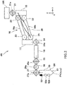
- FIG. 2 is a view schematically illustrating a joint structure of the right arm 4R.
- the right arm 4R is comprised of four kinds of links (15-18) coupled to each other with seven joint shafts (21-27), and the instructing part 5R is provided to the tip end thereof.
- a servo motor for drive, a brake which brakes rotation of the servo motor, and a position sensor which detects a rotational angular position of the servo motor are provided corresponding to each of a first joint shaft 21, second joint shafts 22, a fourth joint shaft 24, a fifth joint shaft 25, a sixth joint shaft 26, and a seventh joint shaft 27, respectively (none of them is illustrated).
- drive shafts among the plurality of joint shafts are indicated by oblique lines.
- the servo motor may be a direct drive motor, or may be provided with a DC motor and a transmission mechanism with a low reduction ratio.
- the position sensor is an encoder, for example.
- the brake is, for example, an excitation-actuated electromagnetic brake which is disengaged when excited by electric power supply, and on the other hand, is engaged when not excited.
- the first link 15 is coupled at one longitudinal end thereof to the branched part 10R of the support 10A ( Fig. 1 ) through the first joint shaft 21, and is coupled at the other longitudinal end to the second link 16 through the pair of second joint shafts 22.
- the first link 15 is supported by the branched part 10R of the support, in a suspended state in which it is horizontally rotatable centering on a first rotational axis 21a of the first joint shaft 21.
- the first rotational axis 21a of the first joint shaft 21 is parallel to the center axis 10a of the support 10A ( Fig. 1 ).
- the second link 16 is comprised of a pair of second link members 16a and 16b parallel to each other. One longitudinal ends of the pair of second link members 16a and 16b are coupled to the first link 15 through the pair of second joint shafts 22, respectively, and the other longitudinal ends of the pair of second link members 16a and 16b are coupled to a third link 17 through a pair of third joint shafts 23, respectively.
- the second link 16 is supported by the first link 15 so as to be vertically rotatable centering on the second joint shafts 22 which have rotational axes perpendicular to the center axis 10a of the support 10A ( Fig. 1 ).
- the third link 17 one longitudinal end is coupled to the second link 16 through the pair of third joint shafts 23.
- the pair of mutually-parallel second link members 16a and 16b which constitute the second link 16, the pair of second joint shafts 22, and the pair of third joint shafts 23 constitute a parallel-link mechanism. Only one of the pair of second joint shafts 22 is a drive shaft, and the other of the pair of second joint shafts 22 and the pair of third joint shafts 23 are driven shafts.
- the third link 17 is uniquely determined when postures of the first link 15 and the second link 16 are fixed.
- the pair of second joint shafts 22 and the pair of third joint shafts 33 are vertically arranged, respectively, the third link 17 moves in a vertical plane defined by the parallel link, while maintaining the uniquely-determined posture.
- the right arm 4R includes a self-weight compensation mechanism 28 which comes the second link 16 to rest with respect to the first link 15 by applying a force in the opposite direction of gravity to the second link 16.
- the self-weight compensation mechanism 28 is comprised of a tension spring in this embodiment, it may be comprised of a balance weight or an auxiliary link. One end of the self-weight compensation mechanism 28 is connected to the first link 15, and the other end is connected to the third joint shaft.
- the second link 16 is capable of coming to rest with respect to the first link 15 at a substantially 90 degrees with respect to the first rotational axis 21 a which is a rotational axis of the first link.
- the other longitudinal end of the third link 17 is coupled to the fourth link 18 through the fourth joint shaft 24.
- the fourth link 18 is coupled at one longitudinal end to the third link 17 through the fourth joint shaft 24.
- the fourth link 18 is supported by the third link 17 so as to be horizontally rotatable centering on a fourth rotational axis 24a of the fourth joint shaft 24.
- the fourth rotational axis 24a of the fourth joint shaft 24 is parallel to the first rotational axis 21a of the first joint shaft 21.
- the other longitudinal end of the fourth link 18 is coupled to the instructing part 5R through the fifth joint shaft 25, the sixth joint shaft 26, and the seventh joint shaft 27.
- the sixth joint shaft 26 is supported by the fourth link 18 so as to be rotatable centering on a fifth rotational axis 25a of the fifth joint shaft 25.
- the fifth rotational axis 25a of the fifth joint shaft 25 is perpendicular to the first rotational axis 21 a and the fourth rotational axis 24a. That is, here, the fifth rotational axis 25a is a horizontal rotational axis.
- the instructing part 5R is coupled at one longitudinal end to the seventh joint shaft.
- the instructing part 5R is supported by the sixth joint shaft 26 so as to be rotatable centering on a seventh rotational axis 27a of the seventh joint shaft 27.
- the rotational axis 26a of the sixth joint shaft is perpendicular to the fifth rotational axis 25a
- the rotational axis 27a of the seventh joint shaft 27 is perpendicular to the sixth rotational axis 26a.
- the instructing part 5R is rotatable with respect to the fourth link 18 in any direction, and is capable of taking any posture.
- the instructing part 5R is comprised of a bar-shaped grip part 50 and a tip-end part 51 which indicates the coordinate point in space.
- the grip part 50 is provided with operation permitting buttons 52a and 52b, and a position registering button 53. They are not limited to the buttons but may be other operational keys.
- the operation permitting buttons 52a and 52b are operational keys for starting a teaching operation.
- the operation permitting button 52a is a button for turning off all the servo motors of the first to sixth joint shafts 21-26 and disengaging the brakes.
- the operation permitting button 52b is a button for turning off the servo motors of three shafts of the first to third joint shafts 21-23 on the main body 10 side and disengaging the brakes.
- the operation permitting buttons 52a and 52b by pressing both the operation permitting buttons 52a and 52b, the servo motors of three shafts of the fourth to sixth joint shafts 24-26 on the tip-end side of the arm are turned off and the brake are disengaged.
- the posture of the hand (the instructing parts 5R and 5L) is adjustable, while the arm position is fixed.
- the operation permitting button 52b may be provided to the fourth link 18 or the fifth link 19.
- the position registering button 53 is an operational key for registering the coordinate point indicated by the instructing part 5R as a teaching point. These buttons may be provided near the instructing part 5R. Thus, since the teacher is easy to operate the buttons with both hands, the teaching operation becomes easier.
- the coordinate point in space is calculated as follows.
- a reference coordinate system (hereinafter, referred to as "the base coordinate system") for the right arm 4R of the dual-arm robot 2, as illustrated in Fig. 2
- the first rotational axis 21a of the first joint shaft 21 is Z-axis
- an arbitrary axis perpendicular to the Z-axis is X-axis
- an axis perpendicular to the Z-axis and the X-axis is Y-axis.
- Fig. 3 is a block diagram illustrating a configuration of the control device 3.
- the control device 3 includes an operation part 31, a memory part 32, and a servo control part 35.
- the control device 3 is, for example, a robot controller provided with a computer, such as a micro controller. In this embodiment, the robot controller has a teaching function of the dual-arm robot 2.
- the control device 3 is not limited to a single device, but may be comprised of a plurality of devices including the robot controller.
- the control device 3 is connected with the operation permitting buttons 52a and 52b and the position registering button 53 through a communication interface (not illustrated), and receives a command signal from each operational key.
- the memory part 32 stores information, such as a basic program as the robot controller, a teaching program of the robot, dimensions of the links, teaching points, and teaching operations.
- the operation part 31 performs calculation processing for a robot control.
- the operation part 31 is configured to achieve each functional block including a control instruction generating module 40, a teaching point acquiring module 41, and an operation generating module 42 (operate as each functional block).
- the control instruction generating module 40 generates a control instruction of the robot 2, and outputs it to the servo control part 35.
- the teaching point acquiring module 41 calculates two coordinate points in the space indicated by the two instructing parts 5R and 5L of the right arm 4R and the left arm 4L to acquire them as the teaching points, respectively.
- the operation generating module 42 generates operations (hereinafter, simply referred to as "the operations") of the two arms, which correspond to the teaching points acquired by the teaching point acquiring module 41.
- the servo control part 35 is configured to control operation of each shaft of the joint shafts 21-26 of the robot 2 based on the control instruction generated by the operation part 31.
- the control instruction generating module 40 when the control device 3 receives an operation permitting signal from at least one of the operation permitting buttons 52a and 52b, the control instruction generating module 40 generates a control instruction based on the operation permitting signal(s), and then outputs the operation permitting signal(s) to the servo control part 35.
- the servo control part 35 controls into a state where the servo motors of the joint shafts are turned off based on the control instruction, and the brakes are disengaged.
- the teaching point acquiring module 41 calculates the coordinate points indicated by the instructing parts 5R and 5L, and registers them as the teaching point, respectively.
- the operation generating module 42 generates operation corresponding to the teaching points acquired by the teaching point acquiring module 41. That is, a sequence program of the robot operation is generated.
- Fig. 4 is a flowchart illustrating one example of procedures of the method of teaching the dual-arm robot 2.
- Figs. 5 and 6 are perspective views illustrating a situation in which the teacher teaches the dual-arm robot 2, when viewed obliquely from front and rear.
- the teacher grips the grip parts 50 of the instructing parts 5L and 5R of the respective arms with both left-and-right hands, sits down on the stool 11, and then performs a teaching work of the dual-arm robot 2.
- the control device 3 is accommodated under the stool 11 in order to save the space.
- the tip end of the support 10A of the robot main body 10 is branched to the branched parts 10L and 10R, a space is produced between the first joint shaft 21 of the arm 4R and the first joint shaft 21 of the arm 4L, thereby there is nothing that interrupts the teacher's view. Therefore, the teacher's view is expanded and the teaching work becomes easier.
- the teacher is able to start the teaching work by pressing either one of the operation permitting buttons 52a and 52b.
- the control device 3 turns off the servo motors of the corresponding shafts of each arm, and disengages the brakes (Step S1).
- the teacher becomes easier to move both the arms by using the backdrive of each arm.
- the servo motors are turned off and the brakes are disengaged, a possibility of the robot going out of control is eliminated completely, and safety is assured.
- self-weight loads of the arms which act on the teacher are reduced by the self-weight compensation mechanisms 28 (see Fig. 2 )
- the teaching becomes easier.
- the teacher moves the two instructing parts 5R and 5L directly and simultaneously with both hands by using the backdrive of the arms (Step S2).
- the second links 16 which are maintained at the angle substantially horizontal with respect to the first links 15 of the arms 4R and 4L by the self-weight compensation mechanisms 28 (see Fig. 2 ) rotate horizontally together with the first links 15, spaces are produced below the first links 15 and the second links 16, and the teacher is able to insert both shoulders into the spaces.
- the shaft joint positions of the two arms 4R and 4L of the dual-arm robot 2 substantially coincide with the shaft joint positions of the teacher's shoulders, and the teaching operation becomes easier.
- control device 3 calculates the positions in the space of the instructing parts 5R and 5L based on the backdrive operation of the arms.
- Step S4 when the teacher presses the position registering buttons 53 of the instructing parts 5R and 5L at arbitrary points, the control device 3 registers the coordinate points indicated by the instructing parts 5R and 5L as the teaching points.
- the position registering button 53 of either one of the instructing parts 5R and 5L is pressed, the teaching points of the two arms 4R and 4L are registered simultaneously.
- the teaching points of the two arms 4R and 4L are registered synchronously.
- the teacher repeats the steps S2-S4 until teaching points required for the teaching operation are registered (Step S5).
- the control device 3 When the registration of the teaching points is completed, the control device 3 generates operation (the sequence program of the robot operation) corresponding to the teaching points (Step S6), and saves the teaching operation (locus of operation) (Step S7) and ends.
- the teaching work is completed only by the operation on the arm side, the teacher does not need to operate other user interfaces (the robot controller, PC, etc.) during the work.
- the coordinate points indicated by the teacher moving the two instructing parts 5R and 5L directly and simultaneously with both hands are acquired as the teaching points, and the operation corresponding to the acquired teaching points is taught to the dual-arm robot 2.
- the route in which the two arms do not interfere with each other is instinctively taught to the dual-arm robot 2.
- exclusive sensors etc. required for the conventional direct teaching are no longer necessary, and the system is configured at low cost.
- the taught robot arm operation substantially coincides with the operation of human arms.
- the operation permitting button 52 and the position registering button 53 are provided to the grip part 50 of the instructing parts 5R and 5L, or near the instructing parts 5R and 5L of the respective arms, they may be disposed on the floor other than on the robot.
- the arms may be moved with both hands, while performing key operations with feet.
- the present disclosure is useful for instructing operation of the dual-arm robot.
Landscapes
- Engineering & Computer Science (AREA)
- Robotics (AREA)
- Mechanical Engineering (AREA)
- Physics & Mathematics (AREA)
- General Physics & Mathematics (AREA)
- Automation & Control Theory (AREA)
- Manipulator (AREA)
Abstract
Description
- The present disclosure relates to a teaching system of a dual-arm robot, and a method of teaching the dual-arm robot.
- Generally, teaching of a robot is performed using a teaching pendant. As for a method of teaching a robot more instinctively, there is direct teaching in which one touches the robot to teach operations (see
Patent Documents 1 to 3). -
- Patent Document 1:
-
JP2013-059852A - Patent Document 2:
-
JP2013-043250A - Patent Document 3:
-
JP2012-157946A - However, in the conventional direct teaching of the robot, exclusive sensors for teaching, such as a joystick and/or a force sensor, need to be used. Thus, a delay occurs in robot operation during the teaching, thereby one feels a sense of discomfort. Furthermore, when a rapid operation is inputted, there is a problem that the robot may perform an abrupt change operation, causing danger, etc.
- Meanwhile, in recent years, in a flow operation line etc., dual-arm robots of about a human size tend to work instead of workers. Generally, there is a problem that teaching of a dual-arm robot is complicated because routes of two arms which avoid interferences therebetween must be found out etc. Therefore, the purpose of the present disclosure is to allow one to perform a teaching work of a dual-arm robot instinctively and easily.
- According to one aspect of the present disclosure, a teaching system of a dual-arm robot includes a dual-arm robot including two arms comprised of a plurality of links coupled to each other with joint shafts, and two instructing parts provided to tip ends of the two arms, respectively, and configured to indicate coordinate points in space and to be grippable by a teacher, and a control device configured to acquire the coordinate points indicated by the teacher moving the two instructing parts directly and simultaneously with both hands as teaching points, and teach the dual-arm robot operation corresponding to the acquired teaching points.
- According to this configuration, the teaching is achieved by the teacher gripping both of the arm tip ends (instructing parts) with both hands and moving the arms directly and simultaneously. Thus, the route in which the arms do not interfere with each other is instinctively taught to the dual-arm robot. Furthermore, exclusive sensors etc. required for the conventional direct teaching are no longer necessary, and the system is configured at low cost.
Each of the arms may include servo motors that drive the joint shafts, respectively, and the control device may acquire the teaching points in a state where the servo motors are turned off and brakes are disengaged. - According to this configuration, by using the backdrive of each arm, the teacher becomes easier to move both the arms and the teaching operation becomes easier. Moreover, since the servo motors are turned off and the brakes are disengaged, a possibility of the robot going out of control is eliminated completely, and safety is assured. For example, the servo motor may be a direct drive motor, or may be provided with a DC motor and a transmission mechanism with a low reduction ratio. Thereby, the backdrive of the arm suitably acts.
- The control device may further include a first operational key configured to turn off the servo motors of each of the arms and disengage the brakes, and a second operational key configured to register the coordinate points indicated by the instructing parts of the respective arms as the teaching points.
- According to this configuration, the teacher is able to start the teaching operation of the arm by the first operational key and register the teaching point at an arbitrary point by the second operational key. Thereby, the teaching operation becomes easier.
- The first operational key and the second operational key may be provided to the respective arms.
According to this configuration, since the teacher becomes easier to perform the key operation with both hands, the teaching operation becomes easier. The first operational key and the second operational key may be provided to each of the instructing parts or near each of the instructing parts. - According to this configuration, the key operation becomes easier and the teaching point can be taught suitably.
- Each of the arms may further include a first link supported by the robot main body so as to be rotatable centering on a vertical rotational axis of a first joint shaft that is used as a fulcrum, a second link supported by the first link so as to be rotatable centering on a horizontal rotational axis of a second joint shaft that is used as a fulcrum, and a self-weight compensation mechanism configured to come the second link to rest with respect to the first link by applying a force in the opposite direction of gravity to the second link.
- According to this configuration, since self-weight loads of the arms which act on the teacher during the teaching are reduced, the teaching becomes easier. For example, the self-weight compensation mechanism may be comprised of a tension spring, a balance weight or an auxiliary link.
- The robot main body may include a support having branched parts of which tip ends are spaced apart from each other and branched to the left and to right, and the first links including base ends of the two arms may be supported by the branched parts of the support so as to be rotatable centering on rotational axes of the first joint shafts that are used as fulcrums, respectively.
- According to this configuration, since the support tip end of the robot main body is branched, a space is produced between the first joint shafts of the two arms, thereby there is nothing that interrupts the teacher's view. Therefore, the teacher's view is expanded and the teaching operation becomes easier.
- The first rotational axis of the first joint shaft may be parallel to a center axis of the support. The system may further include second links and self-weight compensation mechanisms. The first links may be supported by the branched parts of the support in a suspended state so as to be horizontally rotatable centering on the first rotational axis of the first joint shaft. The second link may be supported by the first link so as to be vertically rotatable centering on the second joint shaft having a rotational axis perpendicular to the center axis of the support. The self-weight compensation mechanism may come the second link to rest with respect to the first link at an angle of substantially 90 degrees with respect to the rotational axis of the first link by applying a force in the opposite direction of gravity to the second link.
- According to this configuration, since the second links which are maintained at the angle substantially horizontal with respect to the first links of the arms by the self-weight compensation mechanisms rotate horizontally together with the first links, spaces are produced below the first links and the second links, and the teacher is able to insert both shoulders into the spaces. Thus, the shaft joint positions of the arms of the robot substantially coincide with the shaft joint positions of the teacher's shoulders, and the teaching operation becomes easier.
- According to another aspect of the present disclosure, a method of teaching a dual-arm robot is provided, the dual-arm robot including two arms comprised of a plurality of links coupled to each other with joint shafts, and two instructing parts provided to tip ends of the two arms, respectively, and configured to indicate coordinate points in space and to be grippable by a teacher. The method includes acquiring the coordinate points indicated by the teacher moving the two instructing parts directly and simultaneously with both hands as teaching points, and teaching the dual-arm robot operation corresponding to the acquired teaching points.
- According to the present disclosure, the teaching work of the dual-arm robot is performable instinctively and easily.
- The purpose described above, other purposes, features, and advantages of the present disclosure will be made clear from the following detailed description of a suitable embodiment with reference to the accompanying drawings.
-
-
Fig. 1 is a front view schematically illustrating a configuration of a teaching system of a dual-arm robot according to this embodiment. -
Fig. 2 is a view schematically illustrating a joint structure of a right arm of the dual-arm robot ofFig. 1 . -
Fig. 3 is a block diagram illustrating a configuration of a control device ofFig. 1 . -
Fig. 4 is a flowchart illustrating one example of procedures of a method of teaching the dual-arm robot ofFig. 1 . -
Fig. 5 is a perspective view illustrating a situation in which a teacher teaches the dual-arm robot ofFig. 1 , when viewed obliquely from front. -
Fig. 6 is a perspective view illustrating the situation in which the teacher teaches the dual-arm robot ofFig. 1 , when viewed obliquely from rear. - Hereinafter, one embodiment according to the present disclosure is described with reference to the accompanying drawings. Below, the same reference characters are assigned to the same or corresponding components throughout the drawings to omit redundant description.
-
Fig. 1 is a front view schematically illustrating a configuration of a teaching system of a dual-arm robot according to one embodiment. As illustrated inFig. 1 , therobot teaching system 1 includes a dual-arm robot 2, and acontrol device 3 connected with the dual-arm robot 2 through acontrol line 3a. For this drawing, the forward direction of the dual-arm robot 2 coincide with a direction in which the drawing surface faces. - The dual-
arm robot 2 includes a robotmain body 10, aright arm 4R provided to a right side of the robotmain body 10, and aleft arm 4L provided to a left side of the robotmain body 10. - The robot
main body 10 includes asupport 10A, and apedestal 10B which is installed on a floor surface and supports thesupport 10A. Thesupport 10A has branchedparts stool 11 for a teacher is disposed behind the robotmain body 10. The teacher sits down on thestool 11 and performs a teaching work of the dual-arm robot 2. - The
right arm 4R is comprised of a plurality of links which are coupled to each other with joint shafts. An instructingpart 5R is provided to a tip end of theright arm 4R. The instructingpart 5R indicates a coordinate point in space, and is structured to be grippable by the teacher. - The
left arm 4L is comprised of a plurality of links which are coupled to each other with joint shafts. An instructingpart 5L is provided to a tip end of theleft arm 4L. The instructingpart 5L indicates a coordinate point in space, and is structure to be grippable by the teacher. In this embodiment, the left andright arms center axis 10a of thesupport 10A of the robotmain body 10. - Below, a particular configuration of the
right arm 4R is described.Fig. 2 is a view schematically illustrating a joint structure of theright arm 4R. As illustrated inFig. 2 , theright arm 4R is comprised of four kinds of links (15-18) coupled to each other with seven joint shafts (21-27), and the instructingpart 5R is provided to the tip end thereof. - A servo motor for drive, a brake which brakes rotation of the servo motor, and a position sensor which detects a rotational angular position of the servo motor are provided corresponding to each of a first
joint shaft 21, secondjoint shafts 22, a fourthjoint shaft 24, a fifthjoint shaft 25, a sixthjoint shaft 26, and a seventhjoint shaft 27, respectively (none of them is illustrated). In this drawing, drive shafts among the plurality of joint shafts are indicated by oblique lines. In this embodiment, the servo motor may be a direct drive motor, or may be provided with a DC motor and a transmission mechanism with a low reduction ratio. The position sensor is an encoder, for example. The brake is, for example, an excitation-actuated electromagnetic brake which is disengaged when excited by electric power supply, and on the other hand, is engaged when not excited. - The
first link 15 is coupled at one longitudinal end thereof to thebranched part 10R of thesupport 10A (Fig. 1 ) through the firstjoint shaft 21, and is coupled at the other longitudinal end to thesecond link 16 through the pair of secondjoint shafts 22. Thefirst link 15 is supported by thebranched part 10R of the support, in a suspended state in which it is horizontally rotatable centering on a firstrotational axis 21a of the firstjoint shaft 21. Here, the firstrotational axis 21a of the firstjoint shaft 21 is parallel to thecenter axis 10a of thesupport 10A (Fig. 1 ). - The
second link 16 is comprised of a pair ofsecond link members second link members first link 15 through the pair of secondjoint shafts 22, respectively, and the other longitudinal ends of the pair ofsecond link members third link 17 through a pair of thirdjoint shafts 23, respectively. Thesecond link 16 is supported by thefirst link 15 so as to be vertically rotatable centering on the secondjoint shafts 22 which have rotational axes perpendicular to thecenter axis 10a of thesupport 10A (Fig. 1 ). Moreover, as for thethird link 17, one longitudinal end is coupled to thesecond link 16 through the pair of thirdjoint shafts 23. - Therefore, the pair of mutually-parallel
second link members second link 16, the pair of secondjoint shafts 22, and the pair of thirdjoint shafts 23 constitute a parallel-link mechanism. Only one of the pair of secondjoint shafts 22 is a drive shaft, and the other of the pair of secondjoint shafts 22 and the pair of thirdjoint shafts 23 are driven shafts. - Therefore, the
third link 17 is uniquely determined when postures of thefirst link 15 and thesecond link 16 are fixed. Here, since the pair of secondjoint shafts 22 and the pair of third joint shafts 33 are vertically arranged, respectively, thethird link 17 moves in a vertical plane defined by the parallel link, while maintaining the uniquely-determined posture. Moreover, theright arm 4R includes a self-weight compensation mechanism 28 which comes thesecond link 16 to rest with respect to thefirst link 15 by applying a force in the opposite direction of gravity to thesecond link 16. Although the self-weight compensation mechanism 28 is comprised of a tension spring in this embodiment, it may be comprised of a balance weight or an auxiliary link. One end of the self-weight compensation mechanism 28 is connected to thefirst link 15, and the other end is connected to the third joint shaft. Thus, thesecond link 16 is capable of coming to rest with respect to thefirst link 15 at a substantially 90 degrees with respect to the firstrotational axis 21 a which is a rotational axis of the first link. - The other longitudinal end of the
third link 17 is coupled to thefourth link 18 through the fourthjoint shaft 24. - The
fourth link 18 is coupled at one longitudinal end to thethird link 17 through the fourthjoint shaft 24. Thefourth link 18 is supported by thethird link 17 so as to be horizontally rotatable centering on a fourthrotational axis 24a of the fourthjoint shaft 24. Here, the fourthrotational axis 24a of the fourthjoint shaft 24 is parallel to the firstrotational axis 21a of the firstjoint shaft 21. - The other longitudinal end of the
fourth link 18 is coupled to the instructingpart 5R through the fifthjoint shaft 25, the sixthjoint shaft 26, and the seventhjoint shaft 27. - The sixth
joint shaft 26 is supported by thefourth link 18 so as to be rotatable centering on a fifthrotational axis 25a of the fifthjoint shaft 25. Here, the fifthrotational axis 25a of the fifthjoint shaft 25 is perpendicular to the firstrotational axis 21 a and the fourthrotational axis 24a. That is, here, the fifthrotational axis 25a is a horizontal rotational axis. - The instructing
part 5R is coupled at one longitudinal end to the seventh joint shaft. The instructingpart 5R is supported by the sixthjoint shaft 26 so as to be rotatable centering on a seventhrotational axis 27a of the seventhjoint shaft 27. Here, therotational axis 26a of the sixth joint shaft is perpendicular to the fifthrotational axis 25a, and therotational axis 27a of the seventhjoint shaft 27 is perpendicular to the sixthrotational axis 26a. - Therefore, the instructing
part 5R is rotatable with respect to thefourth link 18 in any direction, and is capable of taking any posture. - The instructing
part 5R is comprised of a bar-shapedgrip part 50 and a tip-end part 51 which indicates the coordinate point in space. Thegrip part 50 is provided withoperation permitting buttons position registering button 53. They are not limited to the buttons but may be other operational keys. - The
operation permitting buttons operation permitting button 52a is a button for turning off all the servo motors of the first to sixth joint shafts 21-26 and disengaging the brakes. Theoperation permitting button 52b is a button for turning off the servo motors of three shafts of the first to third joint shafts 21-23 on themain body 10 side and disengaging the brakes. By using theoperation permitting button 52b, the arm position is adjustable while the posture of the hand (the instructingparts operation permitting buttons parts operation permitting button 52b may be provided to thefourth link 18 or thefifth link 19. - The
position registering button 53 is an operational key for registering the coordinate point indicated by the instructingpart 5R as a teaching point. These buttons may be provided near the instructingpart 5R. Thus, since the teacher is easy to operate the buttons with both hands, the teaching operation becomes easier. - Here, the coordinate point in space is calculated as follows. For example, in a reference coordinate system (hereinafter, referred to as "the base coordinate system") for the
right arm 4R of the dual-arm robot 2, as illustrated inFig. 2 , an intersection between a bottom surface of thebranched part 10R of the support and the firstrotational axis 21a of the firstjoint shaft 21 is an origin, the firstrotational axis 21a of the firstjoint shaft 21 is Z-axis, an arbitrary axis perpendicular to the Z-axis is X-axis, and an axis perpendicular to the Z-axis and the X-axis is Y-axis. Based on the base coordinate system, by storing beforehand angular positions of the first to sixth joint shafts 21-26, dimensions of the links 15-19 and the instructingpart 5R which constitute theright arm 4R, etc., a coordinate point P1 (x, y, z) in the three-dimensional space which is indicated by the tip-end part 51 of the instructingpart 5R is calculatable. -
Fig. 3 is a block diagram illustrating a configuration of thecontrol device 3. As illustrated inFig. 3 , thecontrol device 3 includes anoperation part 31, amemory part 32, and aservo control part 35. Thecontrol device 3 is, for example, a robot controller provided with a computer, such as a micro controller. In this embodiment, the robot controller has a teaching function of the dual-arm robot 2. Thecontrol device 3 is not limited to a single device, but may be comprised of a plurality of devices including the robot controller. Thecontrol device 3 is connected with theoperation permitting buttons position registering button 53 through a communication interface (not illustrated), and receives a command signal from each operational key. - The
memory part 32 stores information, such as a basic program as the robot controller, a teaching program of the robot, dimensions of the links, teaching points, and teaching operations. - The
operation part 31 performs calculation processing for a robot control. Theoperation part 31 is configured to achieve each functional block including a controlinstruction generating module 40, a teachingpoint acquiring module 41, and an operation generating module 42 (operate as each functional block). The controlinstruction generating module 40 generates a control instruction of therobot 2, and outputs it to theservo control part 35. The teachingpoint acquiring module 41 calculates two coordinate points in the space indicated by the two instructingparts right arm 4R and theleft arm 4L to acquire them as the teaching points, respectively. Theoperation generating module 42 generates operations (hereinafter, simply referred to as "the operations") of the two arms, which correspond to the teaching points acquired by the teachingpoint acquiring module 41. - The
servo control part 35 is configured to control operation of each shaft of the joint shafts 21-26 of therobot 2 based on the control instruction generated by theoperation part 31. - With the above configuration, when the
control device 3 receives an operation permitting signal from at least one of theoperation permitting buttons instruction generating module 40 generates a control instruction based on the operation permitting signal(s), and then outputs the operation permitting signal(s) to theservo control part 35. Theservo control part 35 controls into a state where the servo motors of the joint shafts are turned off based on the control instruction, and the brakes are disengaged. Furthermore, when thecontrol device 3 receives a position registering signal from theposition registering button 53, the teachingpoint acquiring module 41 calculates the coordinate points indicated by the instructingparts operation generating module 42 generates operation corresponding to the teaching points acquired by the teachingpoint acquiring module 41. That is, a sequence program of the robot operation is generated. - Next, the method of teaching the dual-
arm robot 2 is described usingFigs. 4 to 6 .Fig. 4 is a flowchart illustrating one example of procedures of the method of teaching the dual-arm robot 2.Figs. 5 and6 are perspective views illustrating a situation in which the teacher teaches the dual-arm robot 2, when viewed obliquely from front and rear. - As illustrated in
Figs. 5 and6 , the teacher grips thegrip parts 50 of the instructingparts stool 11, and then performs a teaching work of the dual-arm robot 2. Here, thecontrol device 3 is accommodated under thestool 11 in order to save the space. Moreover, as illustrated inFig. 5 , since the tip end of thesupport 10A of the robotmain body 10 is branched to the branchedparts joint shaft 21 of thearm 4R and the firstjoint shaft 21 of thearm 4L, thereby there is nothing that interrupts the teacher's view. Therefore, the teacher's view is expanded and the teaching work becomes easier. - Then, the teacher is able to start the teaching work by pressing either one of the
operation permitting buttons control device 3 turns off the servo motors of the corresponding shafts of each arm, and disengages the brakes (Step S1). Thus, the teacher becomes easier to move both the arms by using the backdrive of each arm. Moreover, since the servo motors are turned off and the brakes are disengaged, a possibility of the robot going out of control is eliminated completely, and safety is assured. Moreover, since self-weight loads of the arms which act on the teacher are reduced by the self-weight compensation mechanisms 28 (seeFig. 2 ), the teaching becomes easier. - Next, the teacher moves the two instructing
parts Figs. 5 and6 , since thesecond links 16 which are maintained at the angle substantially horizontal with respect to thefirst links 15 of thearms Fig. 2 ) rotate horizontally together with thefirst links 15, spaces are produced below thefirst links 15 and thesecond links 16, and the teacher is able to insert both shoulders into the spaces. Thus, the shaft joint positions of the twoarms arm robot 2 substantially coincide with the shaft joint positions of the teacher's shoulders, and the teaching operation becomes easier. - Next, the
control device 3 calculates the positions in the space of the instructingparts - Next, when the teacher presses the
position registering buttons 53 of the instructingparts control device 3 registers the coordinate points indicated by the instructingparts position registering button 53 of either one of the instructingparts arms arms - The teacher repeats the steps S2-S4 until teaching points required for the teaching operation are registered (Step S5). When the registration of the teaching points is completed, the
control device 3 generates operation (the sequence program of the robot operation) corresponding to the teaching points (Step S6), and saves the teaching operation (locus of operation) (Step S7) and ends. Thus, since the teaching work is completed only by the operation on the arm side, the teacher does not need to operate other user interfaces (the robot controller, PC, etc.) during the work. - Therefore, according to this embodiment, the coordinate points indicated by the teacher moving the two instructing
parts arm robot 2. Thus, the route in which the two arms do not interfere with each other is instinctively taught to the dual-arm robot 2. Furthermore, exclusive sensors etc. required for the conventional direct teaching are no longer necessary, and the system is configured at low cost. - Moreover, the taught robot arm operation substantially coincides with the operation of human arms. As a result, an administrator of a production site is understandable at a glance of what kind of work the robot is performing and a progress of the work.
- Note that, in this embodiment, although the
operation permitting button 52 and theposition registering button 53 are provided to thegrip part 50 of the instructingparts parts - It is apparent for a person skilled in the art that many improvements and other embodiments of the present disclosure are possible based on the description described above. Therefore, the description described above is to be interpreted only as illustration, and it is provided in order to teach a person skilled in the art the best mode which implements the present disclosure. Details of one or both of the structure and the function can substantially be changed without departing from the spirit of the present disclosure.
- The present disclosure is useful for instructing operation of the dual-arm robot.
-
- 1
- Robot Teaching System
- 2
- Dual-arm Robot
- 3
- Control Device
- 4R, 4L
- Right Arm, Left Arm
- 5R, 5L
- Instructing Part (Right), Instructing Part (Left)
- 10
- Robot Main Body
- 10A
- Support
- 10B
- Pedestal
- 10R, 10L
- Branched Part (Right), Branched Part (Left)
- 11
- Stool
- 15-18
- First to Fourth Links
- 21-27
- First to Seventh Joint Shafts
- 28
- Self-weight Compensation Mechanism
- 30
- Servo Motor
- 31
- Operation Part
- 32
- Memory Part
- 35
- Servo Control Part
- 40
- Control Instruction Generating Module
- 41
- Teaching Point Acquiring Module
- 42
- Operation Generating Module
- 50
- Grip Part
- 51
- Tip-end Part
- 52a, 52b
- Operation Permitting Button (First Operational Key)
- 53
- Position Registering Button (Second Operational Key)
Claims (9)
- A teaching system of a dual-arm robot, comprising:a dual-arm robot including two arms comprised of a plurality of links coupled to each other with joint shafts, and two instructing parts provided to tip ends of the two arms, respectively, and configured to indicate coordinate points in space and to be grippable by a teacher; anda control device configured to acquire the coordinate points indicated by the teacher moving the two instructing parts directly and simultaneously with both hands as teaching points, and teach the dual-arm robot operation corresponding to the acquired teaching points.
- The teaching system of claim 1, wherein,
each of the arms includes servo motors that drive the joint shafts, respectively, and
the control device acquires the teaching points in a state where the servo motors are turned off and brakes are disengaged. - The teaching system of claim 2, wherein the control device further includes a first operational key configured to turn off the servo motors of each of the arms and disengage the brakes, and a second operational key configured to register the coordinate points indicated by the instructing parts of the respective arms as the teaching points.
- The teaching system of claim 3, wherein the first operational key and the second operational key are provided to the respective arms.
- The teaching system of claim 4, wherein the first operational key and the second operational key are provided to each of the instructing parts or near each of the instructing parts.
- The teaching system of any one of claims 1 to 5, wherein each of the arms further includes:a first link supported by the robot main body so as to be rotatable centering on a vertical rotational axis of a first joint shaft that is used as a fulcrum;a second link supported by the first link so as to be rotatable centering on a horizontal rotational axis of a second joint shaft that is used as a fulcrum; anda self-weight compensation mechanism configured to come the second link to rest with respect to the first link by applying a force in the opposite direction of gravity to the second link.
- The teaching system of any one of claims 1 to 6, wherein,
the robot main body includes a support having branched parts of which tip ends are spaced apart from each other and branched to the left and to right, and
the first links including base ends of the two arms are supported by the branched parts of the support so as to be rotatable centering on rotational axes of the first joint shafts that are used as fulcrums, respectively. - The teaching system of claim 7, wherein,
the first rotational axis of the first joint shaft is parallel to a center axis of the support,
the system further comprising second links and self-weight compensation mechanisms,
the first links are supported by the branched parts of the support in a suspended state so as to be horizontally rotatable centering on the first rotational axis of the first joint shaft,
the second link is supported by the first link so as to be vertically rotatable centering on the second joint shaft having a rotational axis perpendicular to the center axis of the support, and
the self-weight compensation mechanism comes the second link to rest with respect to the first link at an angle of substantially 90 degrees with respect to the rotational axis of the first link by applying a force in the opposite direction of gravity to the second link. - A method of teaching a dual-arm robot, the dual-arm robot including two arms comprised of a plurality of links coupled to each other with joint shafts, and two instructing parts provided to tip ends of the two arms, respectively, and configured to indicate coordinate points in space and to be grippable by a teacher, the method comprising:acquiring the coordinate points indicated by the teacher moving the two instructing parts directly and simultaneously with both hands as teaching points; andteaching the dual-arm robot operation corresponding to the acquired teaching points.
Applications Claiming Priority (2)
| Application Number | Priority Date | Filing Date | Title |
|---|---|---|---|
| JP2014266509A JP6630042B2 (en) | 2014-12-26 | 2014-12-26 | Dual arm robot teaching system and dual arm robot teaching method |
| PCT/JP2015/006475 WO2016103729A1 (en) | 2014-12-26 | 2015-12-25 | Dual arm robot teaching system and dual arm robot teaching method |
Publications (3)
| Publication Number | Publication Date |
|---|---|
| EP3238888A1 true EP3238888A1 (en) | 2017-11-01 |
| EP3238888A4 EP3238888A4 (en) | 2018-10-10 |
| EP3238888B1 EP3238888B1 (en) | 2023-03-08 |
Family
ID=56149786
Family Applications (1)
| Application Number | Title | Priority Date | Filing Date |
|---|---|---|---|
| EP15872300.7A Active EP3238888B1 (en) | 2014-12-26 | 2015-12-25 | Dual arm robot teaching system and dual arm robot teaching method |
Country Status (7)
| Country | Link |
|---|---|
| US (1) | US10078327B2 (en) |
| EP (1) | EP3238888B1 (en) |
| JP (1) | JP6630042B2 (en) |
| KR (2) | KR20170097728A (en) |
| CN (1) | CN107107342B (en) |
| TW (1) | TWI623399B (en) |
| WO (1) | WO2016103729A1 (en) |
Cited By (1)
| Publication number | Priority date | Publication date | Assignee | Title |
|---|---|---|---|---|
| CN112549017A (en) * | 2020-10-27 | 2021-03-26 | 南京凌华微电子科技有限公司 | Double-arm robot cooperative space solving method for avoiding joint limit |
Families Citing this family (15)
| Publication number | Priority date | Publication date | Assignee | Title |
|---|---|---|---|---|
| JP6489991B2 (en) * | 2015-10-02 | 2019-03-27 | ファナック株式会社 | Robot operating device having a handle for operating the robot |
| JP2018167334A (en) | 2017-03-29 | 2018-11-01 | セイコーエプソン株式会社 | Teaching device and teaching method |
| CN109202859A (en) * | 2017-06-29 | 2019-01-15 | 沈阳新松机器人自动化股份有限公司 | A kind of robot demonstrator |
| CN109129432A (en) * | 2017-10-27 | 2019-01-04 | 王晶红 | A kind of both arms cooperation robot |
| CN108393894A (en) * | 2018-05-14 | 2018-08-14 | 安徽理工大学 | Both arms casting sample detection robot |
| JP7302182B2 (en) * | 2019-01-29 | 2023-07-04 | セイコーエプソン株式会社 | Horizontal articulated robot |
| DE102019102427B4 (en) * | 2019-01-31 | 2022-02-10 | Franka Emika Gmbh | Coordination of trajectories of two robotic manipulators |
| CN110181490B (en) * | 2019-06-28 | 2023-03-14 | 长沙开山斧智能科技有限公司 | Multi-axis synchronous manipulator and control system thereof |
| JP2021154439A (en) * | 2020-03-27 | 2021-10-07 | セイコーエプソン株式会社 | Teaching method |
| JP6944008B1 (en) * | 2020-03-30 | 2021-10-06 | 川田テクノロジーズ株式会社 | Working robot |
| KR102330992B1 (en) * | 2020-09-25 | 2021-11-24 | 한국로봇융합연구원 | Teaching apparatus for robot and control method of the same |
| KR20220137213A (en) * | 2021-04-01 | 2022-10-12 | 주식회사 제우스 | Delta robot, and control apparatus and method thereof |
| TWI812078B (en) * | 2021-05-14 | 2023-08-11 | 台達電子工業股份有限公司 | Dual-arm robot assembling system |
| CN114332985B (en) * | 2021-12-06 | 2024-06-18 | 上海大学 | Portrait outline intelligent drawing method based on double mechanical arms cooperation |
| CN114536351B (en) * | 2022-04-27 | 2022-07-15 | 季华实验室 | Redundant double-arm robot teaching method and device, electronic equipment and system |
Family Cites Families (15)
| Publication number | Priority date | Publication date | Assignee | Title |
|---|---|---|---|---|
| JPS6080575A (en) * | 1983-10-07 | 1985-05-08 | 松下電器産業株式会社 | Industrial robot |
| JPH0236085A (en) * | 1988-07-25 | 1990-02-06 | Fujitsu Ltd | Direct teaching device for robot |
| JPH08216074A (en) * | 1995-02-17 | 1996-08-27 | Yaskawa Electric Corp | Direct teaching device of robot |
| JPH0962334A (en) * | 1995-08-25 | 1997-03-07 | Fanuc Ltd | Robot controller for safe execution of read-through teaching |
| JPH0985671A (en) * | 1995-09-22 | 1997-03-31 | Daihen Corp | Small-size articulated robot device |
| US8364314B2 (en) | 2009-04-30 | 2013-01-29 | GM Global Technology Operations LLC | Method and apparatus for automatic control of a humanoid robot |
| JP5637883B2 (en) | 2011-02-01 | 2014-12-10 | ファナック株式会社 | Robot teaching device for direct teaching of robots based on force sensor output |
| JP5479541B2 (en) | 2011-08-23 | 2014-04-23 | パナソニック株式会社 | Parallel link robot and its operation teaching method |
| CN102950596B (en) * | 2011-08-23 | 2015-11-11 | 松下电器产业株式会社 | Parallel link robot and action teaching method thereof |
| JP2013043250A (en) | 2011-08-24 | 2013-03-04 | Panasonic Corp | Device and method for controlling robot arm, robot, control program, and integrated electronic circuit |
| WO2013035244A1 (en) * | 2011-09-06 | 2013-03-14 | パナソニック株式会社 | Robotic arm control device and control method, robot, control program and integrated electronic circuit |
| US20130343640A1 (en) * | 2012-06-21 | 2013-12-26 | Rethink Robotics, Inc. | Vision-guided robots and methods of training them |
| JP6110612B2 (en) * | 2012-07-19 | 2017-04-05 | 川崎重工業株式会社 | Substrate transfer device |
| JP2014217913A (en) * | 2013-05-08 | 2014-11-20 | パナソニック株式会社 | Operation teaching method of parallel link robot and parallel link robot |
| JP6440385B2 (en) * | 2014-06-10 | 2018-12-19 | キヤノン株式会社 | Robot arm, display device and robot system |
-
2014
- 2014-12-26 JP JP2014266509A patent/JP6630042B2/en active Active
-
2015
- 2015-12-25 EP EP15872300.7A patent/EP3238888B1/en active Active
- 2015-12-25 WO PCT/JP2015/006475 patent/WO2016103729A1/en active Application Filing
- 2015-12-25 KR KR1020177020086A patent/KR20170097728A/en active Search and Examination
- 2015-12-25 KR KR1020197019646A patent/KR20190085160A/en active Application Filing
- 2015-12-25 TW TW104144017A patent/TWI623399B/en active
- 2015-12-25 CN CN201580071080.2A patent/CN107107342B/en active Active
- 2015-12-25 US US15/539,713 patent/US10078327B2/en active Active
Cited By (1)
| Publication number | Priority date | Publication date | Assignee | Title |
|---|---|---|---|---|
| CN112549017A (en) * | 2020-10-27 | 2021-03-26 | 南京凌华微电子科技有限公司 | Double-arm robot cooperative space solving method for avoiding joint limit |
Also Published As
| Publication number | Publication date |
|---|---|
| TWI623399B (en) | 2018-05-11 |
| EP3238888A4 (en) | 2018-10-10 |
| US20170343998A1 (en) | 2017-11-30 |
| CN107107342B (en) | 2020-06-05 |
| WO2016103729A1 (en) | 2016-06-30 |
| TW201634199A (en) | 2016-10-01 |
| JP6630042B2 (en) | 2020-01-15 |
| KR20190085160A (en) | 2019-07-17 |
| KR20170097728A (en) | 2017-08-28 |
| EP3238888B1 (en) | 2023-03-08 |
| JP2016124065A (en) | 2016-07-11 |
| CN107107342A (en) | 2017-08-29 |
| US10078327B2 (en) | 2018-09-18 |
Similar Documents
| Publication | Publication Date | Title |
|---|---|---|
| EP3238888B1 (en) | Dual arm robot teaching system and dual arm robot teaching method | |
| EP3342541B1 (en) | Remote control robot system | |
| JP5921228B2 (en) | Standing motion support robot | |
| JP6959762B2 (en) | Remote control robot system | |
| JP7187765B2 (en) | robot controller | |
| Luo et al. | Team Northeastern's approach to ANA XPRIZE Avatar final testing: A holistic approach to telepresence and lessons learned | |
| US11305414B2 (en) | Manipulating device | |
| JP6743453B2 (en) | Robot controller, robot and simulation device | |
| JP2022122729A (en) | Teaching device, teaching method and teaching program | |
| JP2016221653A (en) | Robot control device and robot system | |
| JP2020001103A (en) | Robot control system | |
| JP5380192B2 (en) | General-purpose robot movement teaching device | |
| JP7568735B2 (en) | Apparatus, control device, system, method, and computer program for acquiring positional relationship between robot and work equipment | |
| JP7395990B2 (en) | Teaching device, control method and teaching program | |
| JP2000246680A (en) | Manipulator for three-dimensional input | |
| JP2017226021A (en) | Robot, robot control device, and robot system | |
| JP2024140782A (en) | Setting device, setting method and setting program | |
| JP2022122728A (en) | Teaching device, teaching method and teaching program | |
| TW202206242A (en) | Display system and robot system |
Legal Events
| Date | Code | Title | Description |
|---|---|---|---|
| STAA | Information on the status of an ep patent application or granted ep patent |
Free format text: STATUS: THE INTERNATIONAL PUBLICATION HAS BEEN MADE |
|
| PUAI | Public reference made under article 153(3) epc to a published international application that has entered the european phase |
Free format text: ORIGINAL CODE: 0009012 |
|
| STAA | Information on the status of an ep patent application or granted ep patent |
Free format text: STATUS: REQUEST FOR EXAMINATION WAS MADE |
|
| 17P | Request for examination filed |
Effective date: 20170726 |
|
| AK | Designated contracting states |
Kind code of ref document: A1 Designated state(s): AL AT BE BG CH CY CZ DE DK EE ES FI FR GB GR HR HU IE IS IT LI LT LU LV MC MK MT NL NO PL PT RO RS SE SI SK SM TR |
|
| AX | Request for extension of the european patent |
Extension state: BA ME |
|
| DAV | Request for validation of the european patent (deleted) | ||
| DAX | Request for extension of the european patent (deleted) | ||
| A4 | Supplementary search report drawn up and despatched |
Effective date: 20180910 |
|
| RIC1 | Information provided on ipc code assigned before grant |
Ipc: B25J 9/00 20060101ALI20180904BHEP Ipc: B25J 9/22 20060101AFI20180904BHEP Ipc: G05B 19/423 20060101ALI20180904BHEP Ipc: B25J 9/16 20060101ALI20180904BHEP |
|
| STAA | Information on the status of an ep patent application or granted ep patent |
Free format text: STATUS: EXAMINATION IS IN PROGRESS |
|
| 17Q | First examination report despatched |
Effective date: 20210421 |
|
| STAA | Information on the status of an ep patent application or granted ep patent |
Free format text: STATUS: EXAMINATION IS IN PROGRESS |
|
| GRAP | Despatch of communication of intention to grant a patent |
Free format text: ORIGINAL CODE: EPIDOSNIGR1 |
|
| STAA | Information on the status of an ep patent application or granted ep patent |
Free format text: STATUS: GRANT OF PATENT IS INTENDED |
|
| INTG | Intention to grant announced |
Effective date: 20220919 |
|
| GRAS | Grant fee paid |
Free format text: ORIGINAL CODE: EPIDOSNIGR3 |
|
| GRAA | (expected) grant |
Free format text: ORIGINAL CODE: 0009210 |
|
| STAA | Information on the status of an ep patent application or granted ep patent |
Free format text: STATUS: THE PATENT HAS BEEN GRANTED |
|
| AK | Designated contracting states |
Kind code of ref document: B1 Designated state(s): AL AT BE BG CH CY CZ DE DK EE ES FI FR GB GR HR HU IE IS IT LI LT LU LV MC MK MT NL NO PL PT RO RS SE SI SK SM TR |
|
| REG | Reference to a national code |
Ref country code: GB Ref legal event code: FG4D |
|
| REG | Reference to a national code |
Ref country code: CH Ref legal event code: EP Ref country code: AT Ref legal event code: REF Ref document number: 1552274 Country of ref document: AT Kind code of ref document: T Effective date: 20230315 |
|
| REG | Reference to a national code |
Ref country code: DE Ref legal event code: R096 Ref document number: 602015082776 Country of ref document: DE |
|
| REG | Reference to a national code |
Ref country code: IE Ref legal event code: FG4D |
|
| REG | Reference to a national code |
Ref country code: LT Ref legal event code: MG9D |
|
| REG | Reference to a national code |
Ref country code: NL Ref legal event code: MP Effective date: 20230308 |
|
| PG25 | Lapsed in a contracting state [announced via postgrant information from national office to epo] |
Ref country code: RS Free format text: LAPSE BECAUSE OF FAILURE TO SUBMIT A TRANSLATION OF THE DESCRIPTION OR TO PAY THE FEE WITHIN THE PRESCRIBED TIME-LIMIT Effective date: 20230308 Ref country code: NO Free format text: LAPSE BECAUSE OF FAILURE TO SUBMIT A TRANSLATION OF THE DESCRIPTION OR TO PAY THE FEE WITHIN THE PRESCRIBED TIME-LIMIT Effective date: 20230608 Ref country code: LV Free format text: LAPSE BECAUSE OF FAILURE TO SUBMIT A TRANSLATION OF THE DESCRIPTION OR TO PAY THE FEE WITHIN THE PRESCRIBED TIME-LIMIT Effective date: 20230308 Ref country code: LT Free format text: LAPSE BECAUSE OF FAILURE TO SUBMIT A TRANSLATION OF THE DESCRIPTION OR TO PAY THE FEE WITHIN THE PRESCRIBED TIME-LIMIT Effective date: 20230308 Ref country code: HR Free format text: LAPSE BECAUSE OF FAILURE TO SUBMIT A TRANSLATION OF THE DESCRIPTION OR TO PAY THE FEE WITHIN THE PRESCRIBED TIME-LIMIT Effective date: 20230308 Ref country code: ES Free format text: LAPSE BECAUSE OF FAILURE TO SUBMIT A TRANSLATION OF THE DESCRIPTION OR TO PAY THE FEE WITHIN THE PRESCRIBED TIME-LIMIT Effective date: 20230308 |
|
| REG | Reference to a national code |
Ref country code: AT Ref legal event code: MK05 Ref document number: 1552274 Country of ref document: AT Kind code of ref document: T Effective date: 20230308 |
|
| PG25 | Lapsed in a contracting state [announced via postgrant information from national office to epo] |
Ref country code: SE Free format text: LAPSE BECAUSE OF FAILURE TO SUBMIT A TRANSLATION OF THE DESCRIPTION OR TO PAY THE FEE WITHIN THE PRESCRIBED TIME-LIMIT Effective date: 20230308 Ref country code: NL Free format text: LAPSE BECAUSE OF FAILURE TO SUBMIT A TRANSLATION OF THE DESCRIPTION OR TO PAY THE FEE WITHIN THE PRESCRIBED TIME-LIMIT Effective date: 20230308 Ref country code: GR Free format text: LAPSE BECAUSE OF FAILURE TO SUBMIT A TRANSLATION OF THE DESCRIPTION OR TO PAY THE FEE WITHIN THE PRESCRIBED TIME-LIMIT Effective date: 20230609 Ref country code: FI Free format text: LAPSE BECAUSE OF FAILURE TO SUBMIT A TRANSLATION OF THE DESCRIPTION OR TO PAY THE FEE WITHIN THE PRESCRIBED TIME-LIMIT Effective date: 20230308 |
|
| PG25 | Lapsed in a contracting state [announced via postgrant information from national office to epo] |
Ref country code: SM Free format text: LAPSE BECAUSE OF FAILURE TO SUBMIT A TRANSLATION OF THE DESCRIPTION OR TO PAY THE FEE WITHIN THE PRESCRIBED TIME-LIMIT Effective date: 20230308 Ref country code: RO Free format text: LAPSE BECAUSE OF FAILURE TO SUBMIT A TRANSLATION OF THE DESCRIPTION OR TO PAY THE FEE WITHIN THE PRESCRIBED TIME-LIMIT Effective date: 20230308 Ref country code: PT Free format text: LAPSE BECAUSE OF FAILURE TO SUBMIT A TRANSLATION OF THE DESCRIPTION OR TO PAY THE FEE WITHIN THE PRESCRIBED TIME-LIMIT Effective date: 20230710 Ref country code: EE Free format text: LAPSE BECAUSE OF FAILURE TO SUBMIT A TRANSLATION OF THE DESCRIPTION OR TO PAY THE FEE WITHIN THE PRESCRIBED TIME-LIMIT Effective date: 20230308 Ref country code: CZ Free format text: LAPSE BECAUSE OF FAILURE TO SUBMIT A TRANSLATION OF THE DESCRIPTION OR TO PAY THE FEE WITHIN THE PRESCRIBED TIME-LIMIT Effective date: 20230308 Ref country code: AT Free format text: LAPSE BECAUSE OF FAILURE TO SUBMIT A TRANSLATION OF THE DESCRIPTION OR TO PAY THE FEE WITHIN THE PRESCRIBED TIME-LIMIT Effective date: 20230308 |
|
| PG25 | Lapsed in a contracting state [announced via postgrant information from national office to epo] |
Ref country code: SK Free format text: LAPSE BECAUSE OF FAILURE TO SUBMIT A TRANSLATION OF THE DESCRIPTION OR TO PAY THE FEE WITHIN THE PRESCRIBED TIME-LIMIT Effective date: 20230308 Ref country code: PL Free format text: LAPSE BECAUSE OF FAILURE TO SUBMIT A TRANSLATION OF THE DESCRIPTION OR TO PAY THE FEE WITHIN THE PRESCRIBED TIME-LIMIT Effective date: 20230308 Ref country code: IS Free format text: LAPSE BECAUSE OF FAILURE TO SUBMIT A TRANSLATION OF THE DESCRIPTION OR TO PAY THE FEE WITHIN THE PRESCRIBED TIME-LIMIT Effective date: 20230708 |
|
| REG | Reference to a national code |
Ref country code: DE Ref legal event code: R097 Ref document number: 602015082776 Country of ref document: DE |
|
| PLBE | No opposition filed within time limit |
Free format text: ORIGINAL CODE: 0009261 |
|
| STAA | Information on the status of an ep patent application or granted ep patent |
Free format text: STATUS: NO OPPOSITION FILED WITHIN TIME LIMIT |
|
| PGFP | Annual fee paid to national office [announced via postgrant information from national office to epo] |
Ref country code: GB Payment date: 20231220 Year of fee payment: 9 |
|
| PG25 | Lapsed in a contracting state [announced via postgrant information from national office to epo] |
Ref country code: SI Free format text: LAPSE BECAUSE OF FAILURE TO SUBMIT A TRANSLATION OF THE DESCRIPTION OR TO PAY THE FEE WITHIN THE PRESCRIBED TIME-LIMIT Effective date: 20230308 Ref country code: DK Free format text: LAPSE BECAUSE OF FAILURE TO SUBMIT A TRANSLATION OF THE DESCRIPTION OR TO PAY THE FEE WITHIN THE PRESCRIBED TIME-LIMIT Effective date: 20230308 |
|
| PGFP | Annual fee paid to national office [announced via postgrant information from national office to epo] |
Ref country code: FR Payment date: 20231221 Year of fee payment: 9 |
|
| 26N | No opposition filed |
Effective date: 20231211 |
|
| PGFP | Annual fee paid to national office [announced via postgrant information from national office to epo] |
Ref country code: DE Payment date: 20240129 Year of fee payment: 9 |
|
| PG25 | Lapsed in a contracting state [announced via postgrant information from national office to epo] |
Ref country code: IT Free format text: LAPSE BECAUSE OF FAILURE TO SUBMIT A TRANSLATION OF THE DESCRIPTION OR TO PAY THE FEE WITHIN THE PRESCRIBED TIME-LIMIT Effective date: 20230308 |
|
| REG | Reference to a national code |
Ref country code: CH Ref legal event code: PL |
|
| PG25 | Lapsed in a contracting state [announced via postgrant information from national office to epo] |
Ref country code: LU Free format text: LAPSE BECAUSE OF NON-PAYMENT OF DUE FEES Effective date: 20231225 |
|
| PG25 | Lapsed in a contracting state [announced via postgrant information from national office to epo] |
Ref country code: MC Free format text: LAPSE BECAUSE OF FAILURE TO SUBMIT A TRANSLATION OF THE DESCRIPTION OR TO PAY THE FEE WITHIN THE PRESCRIBED TIME-LIMIT Effective date: 20230308 |
|
| REG | Reference to a national code |
Ref country code: BE Ref legal event code: MM Effective date: 20231231 |
|
| PG25 | Lapsed in a contracting state [announced via postgrant information from national office to epo] |
Ref country code: MC Free format text: LAPSE BECAUSE OF FAILURE TO SUBMIT A TRANSLATION OF THE DESCRIPTION OR TO PAY THE FEE WITHIN THE PRESCRIBED TIME-LIMIT Effective date: 20230308 Ref country code: LU Free format text: LAPSE BECAUSE OF NON-PAYMENT OF DUE FEES Effective date: 20231225 |
|
| REG | Reference to a national code |
Ref country code: IE Ref legal event code: MM4A |
|
| PG25 | Lapsed in a contracting state [announced via postgrant information from national office to epo] |
Ref country code: IE Free format text: LAPSE BECAUSE OF NON-PAYMENT OF DUE FEES Effective date: 20231225 |
|
| PG25 | Lapsed in a contracting state [announced via postgrant information from national office to epo] |
Ref country code: BE Free format text: LAPSE BECAUSE OF NON-PAYMENT OF DUE FEES Effective date: 20231231 |