EP4205901A1 - Machine for processing workpieces comprising an interface device - Google Patents
Machine for processing workpieces comprising an interface device Download PDFInfo
- Publication number
- EP4205901A1 EP4205901A1 EP22215330.6A EP22215330A EP4205901A1 EP 4205901 A1 EP4205901 A1 EP 4205901A1 EP 22215330 A EP22215330 A EP 22215330A EP 4205901 A1 EP4205901 A1 EP 4205901A1
- Authority
- EP
- European Patent Office
- Prior art keywords
- machine
- working
- interface device
- workpieces
- logic control
- Prior art date
- Legal status (The legal status is an assumption and is not a legal conclusion. Google has not performed a legal analysis and makes no representation as to the accuracy of the status listed.)
- Granted
Links
Images

Classifications
-
- B—PERFORMING OPERATIONS; TRANSPORTING
- B23—MACHINE TOOLS; METAL-WORKING NOT OTHERWISE PROVIDED FOR
- B23Q—DETAILS, COMPONENTS, OR ACCESSORIES FOR MACHINE TOOLS, e.g. ARRANGEMENTS FOR COPYING OR CONTROLLING; MACHINE TOOLS IN GENERAL CHARACTERISED BY THE CONSTRUCTION OF PARTICULAR DETAILS OR COMPONENTS; COMBINATIONS OR ASSOCIATIONS OF METAL-WORKING MACHINES, NOT DIRECTED TO A PARTICULAR RESULT
- B23Q11/00—Accessories fitted to machine tools for keeping tools or parts of the machine in good working condition or for cooling work; Safety devices specially combined with or arranged in, or specially adapted for use in connection with, machine tools
- B23Q11/08—Protective coverings for parts of machine tools; Splash guards
- B23Q11/0891—Protective coverings for parts of machine tools; Splash guards arranged between the working area and the operator
-
- B—PERFORMING OPERATIONS; TRANSPORTING
- B23—MACHINE TOOLS; METAL-WORKING NOT OTHERWISE PROVIDED FOR
- B23Q—DETAILS, COMPONENTS, OR ACCESSORIES FOR MACHINE TOOLS, e.g. ARRANGEMENTS FOR COPYING OR CONTROLLING; MACHINE TOOLS IN GENERAL CHARACTERISED BY THE CONSTRUCTION OF PARTICULAR DETAILS OR COMPONENTS; COMBINATIONS OR ASSOCIATIONS OF METAL-WORKING MACHINES, NOT DIRECTED TO A PARTICULAR RESULT
- B23Q17/00—Arrangements for observing, indicating or measuring on machine tools
- B23Q17/24—Arrangements for observing, indicating or measuring on machine tools using optics or electromagnetic waves
- B23Q17/2409—Arrangements for indirect observation of the working space using image recording means, e.g. a camera
Definitions
- the present invention relates to a machine for processing wooden workpieces comprising an interface device.
- the invention relates to a machine for machining workpieces made of wood, glass, fiberglass, ceramic, plastic, metal, provided with an interface device of the said type, designed and realized, in particular, to provide information to an operator regarding the state of machine operation, but which can be used for any interface function with the operator.
- the machines for machining wooden workpieces can be working centers, in which the workpiece is generally blocked on a supporting plane and various machining operations are carried out on the workpiece by means of a mobile working unit along three linear axes and rotating around one, two or three rotation axes.
- Machines defined as "pass-through” machines are also known, in which the workpiece is machined while it is moved along an advancement direction and in which there is an entry station, a machining station, and an exit station.
- edge banding machines examples include edge banding machines, molders, drillers, sanders, panel saws, squaring-edge banding machines, and the like.
- the machining station is covered with a closed cover carter, so as to protect both the groups that carry out the machining and the operators located near the machine during operation.
- Said known machines are also provided with interface devices with the operator, such as for example PC machines or crystal liquid display of the LCD-type - Liquid Crystal Display, through which the operator can control its operation in a limited way, i.e., only by entering the data or modifying the machining parameters.
- interface devices with the operator, such as for example PC machines or crystal liquid display of the LCD-type - Liquid Crystal Display, through which the operator can control its operation in a limited way, i.e., only by entering the data or modifying the machining parameters.
- LCD or LED displays work through the use of additional components to be illuminated, i.e., light-emitting diodes used as backlighting of the LCD display.
- an object of the present invention to provide a machine for machining wooden workpieces wherein an operator can interact by means of interface devices having multiple functions.
- Another object of the invention is to provide a machine for machining wooden workpieces wherein it is possible to observe the state of working of the working groups even when the machines are covered by closed carter and directly on the worked workpiece.
- a machine for working workpieces made in wood, glass, fiberglass, ceramic, plastic, metal comprising a logic control unit comprising machining programs to be carried out on said workpieces, a base to support the machine on the ground, a working plane, coupled to said base, for supporting the workpieces, at least one working unit, provided with working tools, for working the workpieces, arranged above to working plane, or arranged below said working plane, a cover frame for the protection of said working unit, said machine being comprising an interface device arranged in said covering frame and operationally connected to said logic control unit.
- said interface device is inserted in said covering frame.
- said covering frame comprises a transparent wall, and said interface device is coupled to said transparent wall.
- said interface device is transparent in order to view the working of said working unit.
- said interface device comprises at least one camera capable of projecting images and/or information on said workpieces in AR - Augmented Reality mode.
- said interface device is provided with a connection module of the wireless type, for exchanging data and/or information with said logic control unit.
- said interface device comprises at least one camera capable of monitoring the internal area of said covering frame in which the working takes place and capable of showing the working on said interface device.
- said interface device is provided with a wireless type connection module, to exchange data and/or information, such as images or videos, with other remote machines and/or devices such as PC and/or mobile devices and/or or with servers cloud.
- said interface device is a display - Interactive Touch, with T-OLED technology - Transparent Organic Light Emitting Device.
- said interface device comprises an active portion configured to allow an operator to modify the working parameters of said machine such as setting and adjustment parameters of said at least one working unit.
- the machine M for working workpieces made in wood, glass, fiberglass, ceramic, plastic, metal, provided with an improved frame, object of the present invention essentially comprises a base 1 to support the machine M on the ground, a working plane 2, for supporting the workpieces to be machined, a working unit 3, provided with working tools for working the workpieces, a cover frame or carter 4, which covers said working unit 3, and a logic control unit U, containing the workpiece machining programs.
- said machine M is a working center.
- Said base 1 is capable of supporting said machine M for resting on the ground.
- Said working plane 2 is arranged above said base 1 and extends along a first direction or development direction X.
- Said working plane 2 comprises an entry portion 21, into which the workpiece to be machined is inserted, a working portion 22, in which the workpiece is machined by said working unit 3, and an exit portion 23, from which comes out the machined workpieces.
- Said working unit 3 is capable of sliding along said working plane 2 to perform workpiece machining.
- Said machine M works in the known "pendulum" mode, therefore the entry portion 21, depending on the position of the working unit 3, can also be the working portion 22 or the exit portion 23, as well as the working portion 22 can be the entry portion 21 or exit portion 23, and the exit portion 23 can be entry portion 21 or the working portion 22.
- Said cover frame or carter 4 covers said working unit 3 and, in the machine shown in figure 1 , it is movable integrally with the working unit along the development direction X, in other types of machines it can be static.
- a portion of said frame 4 comprises an interface device 41.
- said interface device 41 is a part of the frame.
- Said interface device 41 is a window of the cover carter 4, reinforced with transparent protective layers.
- said interface device 41 is coupled to a window of the cover carter 4.
- Said interface device 41 is transparent, and therefore allows an operator to see the operation of said working unit 3 during the machining of the workpieces.
- said interface device 41 is capable of generating superimposed images on the workpieces.
- said interface device 41 can include cameras capable of projecting, on the workpieces, images or symbols or writings, in a user interaction mode of the AR - Augmented Reality type.
- said interface device 41 comprises at least one camera for monitoring the internal area of said cover frame 4, in which the matching takes place, and showing it on said interface device 41.
- Said interface device 41 is capable of emitting its own light, therefore it can be made in different shapes and sizes.
- Said interface device 41 is therefore light, flexible, it allows a wide viewing angle, approximately 90° from the normal straight line to the surface of the device itself, has high contrast, has a saturation of the colors, has a minimum response time, has black images regardless of brightness, has extremely low consumption, can be integrated with automatic operating temperature control and self-diagnostic systems.
- Said interface device 41 comprises wireless connection modules, in particular Bluetooth°, to exchange data and/or information, such as images and videos, with said logic control unit U and with other remote devices or with devices arranged in the plant, wherein said machine M is installed, for example, worn by operators, or with cloud units.
- Said interface device 41 is a ITW - Interactive Touch-Windows display type, with T-OLED - Transparent Organic Light Emitting Device technology, i.e. transparent OLEDs, integrated into the windows of said cover carter 4 of said working unit 3.
- Said interface device 41 comprises an active portion, i.e. of the touch screen type, configured to allow an operator to modify the operating parameters of said machine M, such as setting and adjustment parameters of said at least one working unit 3.
- Said logic control unit U contains the working programs for said workpieces.
- Said logic control unit U is also provided with communication means, such as a connection module of the wireless type, in particular Bluetooth ® , to exchange data and/or information, such as images or videos with remote users, such as assistance centers.
- communication means such as a connection module of the wireless type, in particular Bluetooth ® , to exchange data and/or information, such as images or videos with remote users, such as assistance centers.
- said logic control unit U is configured to send said data and/or information to wearable devices, and/or mobile devices, and/or desktop PCs.
- said logic control unit U is configured to send said data and/or information to a remote cloud server, which in turn sends said signals to wearable devices, and/or mobile devices, and/or desktop PCs.
- Said interface device 41 also allows the operator to modify the operating parameters of the machine M.
- Said interface device 41 exchanges data and/or information with other machines or sensors or devices present in the plant in which the machine M is installed.
- said machine M can learn from the experience and make autonomous decisions, redefining parameters, monitoring conditions, and predicting events.
- said logic control unit U comprises control programs that also allow it to operate in multi-user mode, i.e., by allowing more users to simultaneously access to different navigation menus and choose their own customized contents and the information to be displayed, autonomously and independently, even in different languages.
- said interface device 41 is transparent, it is also possible to allow the operator to interact in augmented reality mode orAR-Augmented Reality mode, i.e., it is possible to show data and/or drawings and/or information on the workpieces being machined, in a complete superposition of the physical workpieces in transit in the machine M or static workpieces.
- said interface device 41 allows several operators to share information, technological parameters related to the machining in progress, process information, working data, setting, and adjustment of the working units and/or used tools, to carry out adjustments, set-up, and regulation of the working groups, directly during the machining, without using auxiliary devices or accessories such as command buttons or touch-pad.
- the machine M' differs from the first embodiment described above solely in that said machine M' is a sander, in which the protective carter is fixed.
- the machine M" differs from the first embodiment described above solely in that said machine M" comprises a sequence of machines arranged in series with each other, like a squaring-edge-banding machine, in which a squaring and an edge banding machine are arranged in series with each other.
- the protective carter is fixed.
- the machine object of the present invention allows an operator to visualize the working unit and to interact with the machine itself during the machining of the workpieces.
- the present invention can also be applied to machines not shown, such as, for example, molders, drilling machines, panel saws, working centers for the working of carpentry elements, painting machines, tenoning machines, working centers for the working of doors and windows
Landscapes
- Engineering & Computer Science (AREA)
- Mechanical Engineering (AREA)
- Physics & Mathematics (AREA)
- Optics & Photonics (AREA)
- Multi-Process Working Machines And Systems (AREA)
- Machine Tool Sensing Apparatuses (AREA)
- Numerical Control (AREA)
Abstract
Description
- The present invention relates to a machine for processing wooden workpieces comprising an interface device.
- In more detail, the invention relates to a machine for machining workpieces made of wood, glass, fiberglass, ceramic, plastic, metal, provided with an interface device of the said type, designed and realized, in particular, to provide information to an operator regarding the state of machine operation, but which can be used for any interface function with the operator.
- In the following, the description will be directed to a machine for machining wooden workpieces equipped with an interface device with the operator, integrated in the frame of the machine, but it is clear that the same should not be considered limited to this specific use.
- As is well known, currently the machines for machining wooden workpieces can be working centers, in which the workpiece is generally blocked on a supporting plane and various machining operations are carried out on the workpiece by means of a mobile working unit along three linear axes and rotating around one, two or three rotation axes.
- Machines defined as "pass-through" machines are also known, in which the workpiece is machined while it is moved along an advancement direction and in which there is an entry station, a machining station, and an exit station.
- Examples of such known machines are edge banding machines, molders, drillers, sanders, panel saws, squaring-edge banding machines, and the like.
- Usually, the machining station is covered with a closed cover carter, so as to protect both the groups that carry out the machining and the operators located near the machine during operation.
- Said known machines are also provided with interface devices with the operator, such as for example PC machines or crystal liquid display of the LCD-type - Liquid Crystal Display, through which the operator can control its operation in a limited way, i.e., only by entering the data or modifying the machining parameters.
- It is clear that the known machines allow an operator to interact with the machine only by means of PC machines equipped with LCD or LED displays, or mobile devices.
- LCD or LED displays work through the use of additional components to be illuminated, i.e., light-emitting diodes used as backlighting of the LCD display.
- In light of the above, it is, therefore, an object of the present invention to provide a machine for machining wooden workpieces wherein an operator can interact by means of interface devices having multiple functions.
- Another object of the invention is to provide a machine for machining wooden workpieces wherein it is possible to observe the state of working of the working groups even when the machines are covered by closed carter and directly on the worked workpiece.
- It is, therefore, specific object of the present invention a machine for working workpieces made in wood, glass, fiberglass, ceramic, plastic, metal, comprising a logic control unit comprising machining programs to be carried out on said workpieces, a base to support the machine on the ground, a working plane, coupled to said base, for supporting the workpieces, at least one working unit, provided with working tools, for working the workpieces, arranged above to working plane, or arranged below said working plane, a cover frame for the protection of said working unit, said machine being comprising an interface device arranged in said covering frame and operationally connected to said logic control unit.
- Further according to the invention, said interface device is inserted in said covering frame.
- Still according to the invention, said covering frame comprises a transparent wall, and said interface device is coupled to said transparent wall.
- Always according to the invention, said interface device is transparent in order to view the working of said working unit.
- Preferably according to the invention, said interface device comprises at least one camera capable of projecting images and/or information on said workpieces in AR - Augmented Reality mode.
- Further according to the invention, said interface device is provided with a connection module of the wireless type, for exchanging data and/or information with said logic control unit.
- Still according to the invention, said interface device comprises at least one camera capable of monitoring the internal area of said covering frame in which the working takes place and capable of showing the working on said interface device.
- Always according to the invention, said interface device is provided with a wireless type connection module, to exchange data and/or information, such as images or videos, with other remote machines and/or devices such as PC and/or mobile devices and/or or with servers cloud.
- Preferably according to the invention, said interface device is a display - Interactive Touch, with T-OLED technology - Transparent Organic Light Emitting Device.
- Further according to the invention, said interface device comprises an active portion configured to allow an operator to modify the working parameters of said machine such as setting and adjustment parameters of said at least one working unit.
- The present invention will be now described, for illustrative but not limitative purposes, according to its preferred embodiments, with particular reference to the figures of the enclosed drawings, wherein:
-
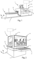
figure 1 shows a perspective view of a first embodiment of the machine for machining wooden workpieces provided with an improved frame, object of the present invention, in which the machine is a working center; -
figure 2 shows a perspective view of a second embodiment of the machine for machining wooden workpieces provided with an improved frame, object of the present invention, in which the machine is a sander; and -
figure 3 shows a perspective view of a third embodiment of the machine for machining wooden workpieces provided with an improved frame, object of the present invention, in which the machine is a squaring-edge-banding machine. - In the various figures, similar parts will be indicated with the same reference numbers.
- With reference to
figure 1 , the machine M for working workpieces made in wood, glass, fiberglass, ceramic, plastic, metal, provided with an improved frame, object of the present invention, essentially comprises abase 1 to support the machine M on the ground, a workingplane 2, for supporting the workpieces to be machined, a workingunit 3, provided with working tools for working the workpieces, a cover frame orcarter 4, which covers said workingunit 3, and a logic control unit U, containing the workpiece machining programs. - In this first embodiment, said machine M is a working center.
- Said
base 1 is capable of supporting said machine M for resting on the ground. - Said working
plane 2 is arranged above saidbase 1 and extends along a first direction or development direction X. - Said working
plane 2 comprises anentry portion 21, into which the workpiece to be machined is inserted, a workingportion 22, in which the workpiece is machined by said workingunit 3, and anexit portion 23, from which comes out the machined workpieces. - Said working
unit 3 is capable of sliding along said workingplane 2 to perform workpiece machining. Said machine M works in the known "pendulum" mode, therefore theentry portion 21, depending on the position of the workingunit 3, can also be the workingportion 22 or theexit portion 23, as well as the workingportion 22 can be theentry portion 21 orexit portion 23, and theexit portion 23 can beentry portion 21 or the workingportion 22. - Said cover frame or
carter 4 covers said workingunit 3 and, in the machine shown infigure 1 , it is movable integrally with the working unit along the development direction X, in other types of machines it can be static. - A portion of said
frame 4 comprises aninterface device 41. - In particular, said
interface device 41 is a part of the frame. - Said
interface device 41 is a window of thecover carter 4, reinforced with transparent protective layers. - Alternatively, said
interface device 41 is coupled to a window of thecover carter 4. - Said
interface device 41 is transparent, and therefore allows an operator to see the operation of said workingunit 3 during the machining of the workpieces. - Furthermore, said
interface device 41 is capable of generating superimposed images on the workpieces. - Furthermore, said
interface device 41 can include cameras capable of projecting, on the workpieces, images or symbols or writings, in a user interaction mode of the AR - Augmented Reality type. - Furthermore, said
interface device 41 comprises at least one camera for monitoring the internal area of saidcover frame 4, in which the matching takes place, and showing it on saidinterface device 41. - Said
interface device 41 is capable of emitting its own light, therefore it can be made in different shapes and sizes. - Said
interface device 41 is therefore light, flexible, it allows a wide viewing angle, approximately 90° from the normal straight line to the surface of the device itself, has high contrast, has a saturation of the colors, has a minimum response time, has black images regardless of brightness, has extremely low consumption, can be integrated with automatic operating temperature control and self-diagnostic systems. - Said
interface device 41 comprises wireless connection modules, in particular Bluetooth°, to exchange data and/or information, such as images and videos, with said logic control unit U and with other remote devices or with devices arranged in the plant, wherein said machine M is installed, for example, worn by operators, or with cloud units. - Said
interface device 41 is a ITW - Interactive Touch-Windows display type, with T-OLED - Transparent Organic Light Emitting Device technology, i.e. transparent OLEDs, integrated into the windows of saidcover carter 4 of said workingunit 3. - Said
interface device 41 comprises an active portion, i.e. of the touch screen type, configured to allow an operator to modify the operating parameters of said machine M, such as setting and adjustment parameters of said at least one workingunit 3. - Said logic control unit U contains the working programs for said workpieces.
- Said logic control unit U is also provided with communication means, such as a connection module of the wireless type, in particular Bluetooth®, to exchange data and/or information, such as images or videos with remote users, such as assistance centers.
- Furthermore, said logic control unit U is configured to send said data and/or information to wearable devices, and/or mobile devices, and/or desktop PCs.
- Furthermore, said logic control unit U is configured to send said data and/or information to a remote cloud server, which in turn sends said signals to wearable devices, and/or mobile devices, and/or desktop PCs.
- The operation of the machine M for working wooden workpieces provided with an
interface device 41 described above is as follows. - When the machine M is machining wooden workpieces, the operator can view the operation of said working
unit 3 through saidtransparent interface device 41. - Said
interface device 41 also allows the operator to modify the operating parameters of the machine M. - Said
interface device 41 exchanges data and/or information with other machines or sensors or devices present in the plant in which the machine M is installed. - Thus, it occurs constant feedback on machining and a continuous exchange of data and/or information between man-machine and machine-machine.
- Furthermore, by means of said
interface device 41, said machine M can learn from the experience and make autonomous decisions, redefining parameters, monitoring conditions, and predicting events. - It is also possible that said logic control unit U comprises control programs that also allow it to operate in multi-user mode, i.e., by allowing more users to simultaneously access to different navigation menus and choose their own customized contents and the information to be displayed, autonomously and independently, even in different languages.
- For example, it is possible to insert in said logic control unit U dynamic customized menus, for collaborative applications by operators with different tasks, such as maintenance technicians, process/production managers, or to share or transfer various screens between devices or different screens.
- Furthermore, since said
interface device 41 is transparent, it is also possible to allow the operator to interact in augmented reality mode orAR-Augmented Reality mode, i.e., it is possible to show data and/or drawings and/or information on the workpieces being machined, in a complete superposition of the physical workpieces in transit in the machine M or static workpieces. - Furthermore, said
interface device 41 allows several operators to share information, technological parameters related to the machining in progress, process information, working data, setting, and adjustment of the working units and/or used tools, to carry out adjustments, set-up, and regulation of the working groups, directly during the machining, without using auxiliary devices or accessories such as command buttons or touch-pad. - Furthermore, it is also possible to directly access into the machine M, and during the machining, to an internet browser or data and cloud resources, to acquire and use process information, technical data sheets, company maintenance services, service, spare parts, and the like.
- It is also possible to directly interconnect several machines in line or of the same type, even separated from each other, to share data and/or technology and process information, for example, to control or regulate the working groups of a machine connected in series to the machine M, or be able to view, from the display of a working center of a certain department, the production data, efficiency or status of other machines of the same type, group, and department.
- With reference to
figure 2 , in a second embodiment, the machine M' differs from the first embodiment described above solely in that said machine M' is a sander, in which the protective carter is fixed. - With reference to
figure 3 , in a third embodiment, the machine M" differs from the first embodiment described above solely in that said machine M" comprises a sequence of machines arranged in series with each other, like a squaring-edge-banding machine, in which a squaring and an edge banding machine are arranged in series with each other. - In particular, in the edge-bending machine shown in the figure, the protective carter is fixed.
- As is evident from the description above, the machine object of the present invention allows an operator to visualize the working unit and to interact with the machine itself during the machining of the workpieces.
- The present invention has been described for illustrative but non-limiting purposes, according to its preferred embodiments, but it is to be understood that modifications and/or changes can be introduced by those skilled in the art without departing from the relevant scope of protection, as defined by the enclosed claims.
- In fact, the present invention can also be applied to machines not shown, such as, for example, molders, drilling machines, panel saws, working centers for the working of carpentry elements, painting machines, tenoning machines, working centers for the working of doors and windows
Claims (10)
- Machine (M, M', M") for working workpieces made in wood, glass, fiberglass, ceramic, plastic, metal, comprisinga logic control unit (U) comprising machining programs to be carried out on said workpieces,a base (1) to support the machine (M, M', M") on the ground,a working plane (2), coupled to said base, for supporting the workpieces,at least one working unit (3), provided with working tools, for working the workpieces, arranged above said working plane (2), or arranged below said working plane (2),a cover frame (4) for the protection of said processing unit (3),said machine (M, M', M") being characterized in that it comprises an interface device (41) arranged in said covering frame (4) and operationally connected to said logic control unit (U).
- Machine (M, M', M") according to the preceding claim, characterized in that said interface device (41) is inserted in said covering frame (4).
- Machine (M, M', M") according to claim 1, characterizedin that said covering frame (4) comprises a transparent wall, andin that said interface device (41) is coupled to said transparent wall.
- Machine (M, M', M") according to any one of the preceding claims, characterized in that said interface device (41) is transparent, in order to view the processing of said working unit (3).
- Machine (M, M', M") according to any one of the preceding claims, characterized in that said interface device (41) comprises at least one camera capable of projecting images and/or information on said workpieces in AR - Augmented Reality mode.
- Machine (M, M', M") according to any one of the preceding claims, characterized in that said interface device (41) is provided with a connection module of the wireless type, to exchange data and/or information with said logic control unit (U).
- Machine (M, M', M") according to any one of the preceding claims, characterized in that said interface device (41) comprises at least one camera capable of monitoring the internal area of said covering frame (4), in which the processing takes place and capable of showing the working on said interface device (41).
- Machine (M, M', M") according to any one of the preceding claims, characterized in that said interface device (41) is provided with a wireless type connection module, to exchange data and/or information, such as images or videos, with other remote machines and/or devices such as PC and/or mobile devices and/or with servers cloud.
- Machine (M, M', M") according to any one of the preceding claims, characterized in that said interface device (41) is a display - Interactive Touch, with T-OLED technology - Transparent Organic Light Emitting Device.
- Machine (M, M', M") according to any one of the preceding claims, characterized in that said interface device (41) comprises an active portion configured to allow an operator to modify the working parameters of said machine (M, M', M") as setting and adjustment parameters of said at least one processing unit (3).
Applications Claiming Priority (1)
| Application Number | Priority Date | Filing Date | Title |
|---|---|---|---|
| IT102021000033101A IT202100033101A1 (en) | 2021-12-30 | 2021-12-30 | Machine for processing wooden pieces including an interface device. |
Publications (2)
| Publication Number | Publication Date |
|---|---|
| EP4205901A1 true EP4205901A1 (en) | 2023-07-05 |
| EP4205901B1 EP4205901B1 (en) | 2026-03-04 |
Family
ID=80685394
Family Applications (1)
| Application Number | Title | Priority Date | Filing Date |
|---|---|---|---|
| EP22215330.6A Active EP4205901B1 (en) | 2021-12-30 | 2022-12-21 | Machine for processing workpieces comprising an interface device |
Country Status (2)
| Country | Link |
|---|---|
| EP (1) | EP4205901B1 (en) |
| IT (1) | IT202100033101A1 (en) |
Citations (4)
| Publication number | Priority date | Publication date | Assignee | Title |
|---|---|---|---|---|
| KR101670862B1 (en) * | 2016-02-17 | 2016-11-04 | (주)아이포 | authentication processing method for machine connected service and authentication platform |
| EP3348350A1 (en) * | 2017-01-16 | 2018-07-18 | Nakamura-Tome Precision Industry Co., Ltd | Machine tool with camera |
| US20210260711A1 (en) * | 2020-02-26 | 2021-08-26 | Disco Corporation | Processing apparatus |
| WO2021225584A1 (en) * | 2020-05-05 | 2021-11-11 | Hitachi America, Ltd. | A robust two-in-one sensor signal acquisition method for online manufacturing process and tool condition monitoring system |
Family Cites Families (3)
| Publication number | Priority date | Publication date | Assignee | Title |
|---|---|---|---|---|
| DE10325895A1 (en) * | 2003-06-06 | 2005-01-05 | Siemens Ag | Tool or production machine with head-up display |
| DE102014000789A1 (en) * | 2014-01-22 | 2015-07-23 | Mimot Gmbh | Machine tool with display device |
| KR101843992B1 (en) * | 2017-11-30 | 2018-05-14 | 재단법인 구미전자정보기술원 | Augmented reality based cannula guide system for interventional cardiology procedures and method thereof |
-
2021
- 2021-12-30 IT IT102021000033101A patent/IT202100033101A1/en unknown
-
2022
- 2022-12-21 EP EP22215330.6A patent/EP4205901B1/en active Active
Patent Citations (4)
| Publication number | Priority date | Publication date | Assignee | Title |
|---|---|---|---|---|
| KR101670862B1 (en) * | 2016-02-17 | 2016-11-04 | (주)아이포 | authentication processing method for machine connected service and authentication platform |
| EP3348350A1 (en) * | 2017-01-16 | 2018-07-18 | Nakamura-Tome Precision Industry Co., Ltd | Machine tool with camera |
| US20210260711A1 (en) * | 2020-02-26 | 2021-08-26 | Disco Corporation | Processing apparatus |
| WO2021225584A1 (en) * | 2020-05-05 | 2021-11-11 | Hitachi America, Ltd. | A robust two-in-one sensor signal acquisition method for online manufacturing process and tool condition monitoring system |
Also Published As
| Publication number | Publication date |
|---|---|
| IT202100033101A1 (en) | 2023-06-30 |
| EP4205901B1 (en) | 2026-03-04 |
Similar Documents
| Publication | Publication Date | Title |
|---|---|---|
| US7296956B2 (en) | Machine-tool or production machine with head-up display | |
| US7444201B2 (en) | Machine tool or production machine with a display unit for visually displaying operating sequences | |
| US11339036B2 (en) | Control stand for a crane, excavator, and the like | |
| KR102013012B1 (en) | Portable-type operation instruction input device and device provided with portable-type operation instruction input device | |
| JP6914329B2 (en) | Manual workshop unit, remote data processing device, manual workshop operation system, manual workshop operation method, and manual workshop provision method | |
| US20200125064A1 (en) | Method for monitoring a manufacturing process | |
| CN101351599A (en) | Maintenance history information management system for construction machine | |
| WO2015063828A1 (en) | Working machine and working machine line | |
| EP4205901B1 (en) | Machine for processing workpieces comprising an interface device | |
| CN101362333A (en) | Controller for robot having robot body and additional mechanism providing additional operation axes | |
| CN104977900A (en) | Machine state display device of composite lathe having a plurality of main spindles | |
| US20050209711A1 (en) | Control system and method for controlling one or serveral manipulators | |
| US20050192684A1 (en) | Device for automating machine tools or production machines | |
| Krauß et al. | Digital manufacturing for smart small satellites systems | |
| JP6873592B2 (en) | Operating parts and industrial machinery system | |
| Zakoldaev et al. | Implementation of H2M technology and augmented reality for operation of cyber-physical production of the Industry 4.0 | |
| JPWO2019116462A1 (en) | Manufacturing system | |
| CN114067657A (en) | Real teaching system that instructs of assembly line | |
| JP2015098063A (en) | Processing device | |
| KR102858921B1 (en) | Processing apparatus | |
| WO2018047309A1 (en) | Machining system | |
| KR20150044241A (en) | Apparatus for teaching of robot pose Pendant Equipped Slide-out | |
| WO2022201850A1 (en) | Machine tool | |
| JP2013045867A (en) | Processing device | |
| CN107390633A (en) | A kind of machining tool with error correcting function |
Legal Events
| Date | Code | Title | Description |
|---|---|---|---|
| PUAI | Public reference made under article 153(3) epc to a published international application that has entered the european phase |
Free format text: ORIGINAL CODE: 0009012 |
|
| STAA | Information on the status of an ep patent application or granted ep patent |
Free format text: STATUS: THE APPLICATION HAS BEEN PUBLISHED |
|
| AK | Designated contracting states |
Kind code of ref document: A1 Designated state(s): AL AT BE BG CH CY CZ DE DK EE ES FI FR GB GR HR HU IE IS IT LI LT LU LV MC ME MK MT NL NO PL PT RO RS SE SI SK SM TR |
|
| STAA | Information on the status of an ep patent application or granted ep patent |
Free format text: STATUS: REQUEST FOR EXAMINATION WAS MADE |
|
| 17P | Request for examination filed |
Effective date: 20231221 |
|
| RBV | Designated contracting states (corrected) |
Designated state(s): AL AT BE BG CH CY CZ DE DK EE ES FI FR GB GR HR HU IE IS IT LI LT LU LV MC ME MK MT NL NO PL PT RO RS SE SI SK SM TR |
|
| STAA | Information on the status of an ep patent application or granted ep patent |
Free format text: STATUS: EXAMINATION IS IN PROGRESS |
|
| 17Q | First examination report despatched |
Effective date: 20250224 |
|
| GRAP | Despatch of communication of intention to grant a patent |
Free format text: ORIGINAL CODE: EPIDOSNIGR1 |
|
| STAA | Information on the status of an ep patent application or granted ep patent |
Free format text: STATUS: GRANT OF PATENT IS INTENDED |
|
| INTG | Intention to grant announced |
Effective date: 20251006 |
|
| GRAS | Grant fee paid |
Free format text: ORIGINAL CODE: EPIDOSNIGR3 |
|
| GRAA | (expected) grant |
Free format text: ORIGINAL CODE: 0009210 |
|
| STAA | Information on the status of an ep patent application or granted ep patent |
Free format text: STATUS: THE PATENT HAS BEEN GRANTED |
|
| AK | Designated contracting states |
Kind code of ref document: B1 Designated state(s): AL AT BE BG CH CY CZ DE DK EE ES FI FR GB GR HR HU IE IS IT LI LT LU LV MC ME MK MT NL NO PL PT RO RS SE SI SK SM TR |
|
| REG | Reference to a national code |
Ref country code: CH Ref legal event code: F10 Free format text: ST27 STATUS EVENT CODE: U-0-0-F10-F00 (AS PROVIDED BY THE NATIONAL OFFICE) Effective date: 20260304 Ref country code: GB Ref legal event code: FG4D |
|
| REG | Reference to a national code |
Ref country code: DE Ref legal event code: R096 Ref document number: 602022031550 Country of ref document: DE |
|
| REG | Reference to a national code |
Ref country code: IE Ref legal event code: FG4D |