EP4205802B1 - Mehrschwellenwertmessung von elektrischen herzsignalen in einer implantierbaren medizinischen vorrichtung - Google Patents
Mehrschwellenwertmessung von elektrischen herzsignalen in einer implantierbaren medizinischen vorrichtung Download PDFInfo
- Publication number
- EP4205802B1 EP4205802B1 EP23156009.5A EP23156009A EP4205802B1 EP 4205802 B1 EP4205802 B1 EP 4205802B1 EP 23156009 A EP23156009 A EP 23156009A EP 4205802 B1 EP4205802 B1 EP 4205802B1
- Authority
- EP
- European Patent Office
- Prior art keywords
- interval
- wave
- sensing
- cardiac
- threshold
- Prior art date
- Legal status (The legal status is an assumption and is not a legal conclusion. Google has not performed a legal analysis and makes no representation as to the accuracy of the status listed.)
- Active
Links
Images


Classifications
-
- A—HUMAN NECESSITIES
- A61—MEDICAL OR VETERINARY SCIENCE; HYGIENE
- A61N—ELECTROTHERAPY; MAGNETOTHERAPY; RADIATION THERAPY; ULTRASOUND THERAPY
- A61N1/00—Electrotherapy; Circuits therefor
- A61N1/18—Applying electric currents by contact electrodes
- A61N1/32—Applying electric currents by contact electrodes alternating or intermittent currents
- A61N1/38—Applying electric currents by contact electrodes alternating or intermittent currents for producing shock effects
- A61N1/39—Heart defibrillators
- A61N1/3956—Implantable devices for applying electric shocks to the heart, e.g. for cardioversion
-
- A—HUMAN NECESSITIES
- A61—MEDICAL OR VETERINARY SCIENCE; HYGIENE
- A61B—DIAGNOSIS; SURGERY; IDENTIFICATION
- A61B5/00—Measuring for diagnostic purposes; Identification of persons
- A61B5/24—Detecting, measuring or recording bioelectric or biomagnetic signals of the body or parts thereof
- A61B5/316—Modalities, i.e. specific diagnostic methods
- A61B5/318—Heart-related electrical modalities, e.g. electrocardiography [ECG]
- A61B5/346—Analysis of electrocardiograms
- A61B5/349—Detecting specific parameters of the electrocardiograph cycle
- A61B5/361—Detecting fibrillation
-
- A—HUMAN NECESSITIES
- A61—MEDICAL OR VETERINARY SCIENCE; HYGIENE
- A61N—ELECTROTHERAPY; MAGNETOTHERAPY; RADIATION THERAPY; ULTRASOUND THERAPY
- A61N1/00—Electrotherapy; Circuits therefor
- A61N1/18—Applying electric currents by contact electrodes
- A61N1/32—Applying electric currents by contact electrodes alternating or intermittent currents
- A61N1/36—Applying electric currents by contact electrodes alternating or intermittent currents for stimulation
- A61N1/362—Heart stimulators
- A61N1/3621—Heart stimulators for treating or preventing abnormally high heart rate
- A61N1/3622—Heart stimulators for treating or preventing abnormally high heart rate comprising two or more electrodes co-operating with different heart regions
-
- A—HUMAN NECESSITIES
- A61—MEDICAL OR VETERINARY SCIENCE; HYGIENE
- A61N—ELECTROTHERAPY; MAGNETOTHERAPY; RADIATION THERAPY; ULTRASOUND THERAPY
- A61N1/00—Electrotherapy; Circuits therefor
- A61N1/18—Applying electric currents by contact electrodes
- A61N1/32—Applying electric currents by contact electrodes alternating or intermittent currents
- A61N1/36—Applying electric currents by contact electrodes alternating or intermittent currents for stimulation
- A61N1/362—Heart stimulators
- A61N1/365—Heart stimulators controlled by a physiological parameter, e.g. heart potential
-
- A—HUMAN NECESSITIES
- A61—MEDICAL OR VETERINARY SCIENCE; HYGIENE
- A61N—ELECTROTHERAPY; MAGNETOTHERAPY; RADIATION THERAPY; ULTRASOUND THERAPY
- A61N1/00—Electrotherapy; Circuits therefor
- A61N1/18—Applying electric currents by contact electrodes
- A61N1/32—Applying electric currents by contact electrodes alternating or intermittent currents
- A61N1/36—Applying electric currents by contact electrodes alternating or intermittent currents for stimulation
- A61N1/362—Heart stimulators
- A61N1/37—Monitoring; Protecting
- A61N1/3702—Physiological parameters
-
- A—HUMAN NECESSITIES
- A61—MEDICAL OR VETERINARY SCIENCE; HYGIENE
- A61N—ELECTROTHERAPY; MAGNETOTHERAPY; RADIATION THERAPY; ULTRASOUND THERAPY
- A61N1/00—Electrotherapy; Circuits therefor
- A61N1/18—Applying electric currents by contact electrodes
- A61N1/32—Applying electric currents by contact electrodes alternating or intermittent currents
- A61N1/36—Applying electric currents by contact electrodes alternating or intermittent currents for stimulation
- A61N1/372—Arrangements in connection with the implantation of stimulators
- A61N1/37211—Means for communicating with stimulators
- A61N1/37252—Details of algorithms or data aspects of communication system, e.g. handshaking, transmitting specific data or segmenting data
-
- A—HUMAN NECESSITIES
- A61—MEDICAL OR VETERINARY SCIENCE; HYGIENE
- A61N—ELECTROTHERAPY; MAGNETOTHERAPY; RADIATION THERAPY; ULTRASOUND THERAPY
- A61N1/00—Electrotherapy; Circuits therefor
- A61N1/18—Applying electric currents by contact electrodes
- A61N1/32—Applying electric currents by contact electrodes alternating or intermittent currents
- A61N1/38—Applying electric currents by contact electrodes alternating or intermittent currents for producing shock effects
- A61N1/39—Heart defibrillators
- A61N1/3956—Implantable devices for applying electric shocks to the heart, e.g. for cardioversion
- A61N1/3962—Implantable devices for applying electric shocks to the heart, e.g. for cardioversion in combination with another heart therapy
- A61N1/39622—Pacing therapy
-
- A—HUMAN NECESSITIES
- A61—MEDICAL OR VETERINARY SCIENCE; HYGIENE
- A61B—DIAGNOSIS; SURGERY; IDENTIFICATION
- A61B5/00—Measuring for diagnostic purposes; Identification of persons
- A61B5/24—Detecting, measuring or recording bioelectric or biomagnetic signals of the body or parts thereof
- A61B5/316—Modalities, i.e. specific diagnostic methods
- A61B5/318—Heart-related electrical modalities, e.g. electrocardiography [ECG]
- A61B5/346—Analysis of electrocardiograms
- A61B5/349—Detecting specific parameters of the electrocardiograph cycle
- A61B5/352—Detecting R peaks, e.g. for synchronising diagnostic apparatus; Estimating R-R interval
-
- A—HUMAN NECESSITIES
- A61—MEDICAL OR VETERINARY SCIENCE; HYGIENE
- A61N—ELECTROTHERAPY; MAGNETOTHERAPY; RADIATION THERAPY; ULTRASOUND THERAPY
- A61N1/00—Electrotherapy; Circuits therefor
- A61N1/02—Details
- A61N1/04—Electrodes
- A61N1/05—Electrodes for implantation or insertion into the body, e.g. heart electrode
-
- A—HUMAN NECESSITIES
- A61—MEDICAL OR VETERINARY SCIENCE; HYGIENE
- A61N—ELECTROTHERAPY; MAGNETOTHERAPY; RADIATION THERAPY; ULTRASOUND THERAPY
- A61N1/00—Electrotherapy; Circuits therefor
- A61N1/18—Applying electric currents by contact electrodes
- A61N1/32—Applying electric currents by contact electrodes alternating or intermittent currents
- A61N1/38—Applying electric currents by contact electrodes alternating or intermittent currents for producing shock effects
- A61N1/39—Heart defibrillators
- A61N1/3925—Monitoring; Protecting
- A61N1/3931—Protecting, e.g. back-up systems
-
- A—HUMAN NECESSITIES
- A61—MEDICAL OR VETERINARY SCIENCE; HYGIENE
- A61N—ELECTROTHERAPY; MAGNETOTHERAPY; RADIATION THERAPY; ULTRASOUND THERAPY
- A61N1/00—Electrotherapy; Circuits therefor
- A61N1/18—Applying electric currents by contact electrodes
- A61N1/32—Applying electric currents by contact electrodes alternating or intermittent currents
- A61N1/38—Applying electric currents by contact electrodes alternating or intermittent currents for producing shock effects
- A61N1/39—Heart defibrillators
- A61N1/3925—Monitoring; Protecting
- A61N1/3937—Monitoring output parameters
- A61N1/3943—Monitoring output parameters for threshold determination
-
- A—HUMAN NECESSITIES
- A61—MEDICAL OR VETERINARY SCIENCE; HYGIENE
- A61N—ELECTROTHERAPY; MAGNETOTHERAPY; RADIATION THERAPY; ULTRASOUND THERAPY
- A61N1/00—Electrotherapy; Circuits therefor
- A61N1/18—Applying electric currents by contact electrodes
- A61N1/32—Applying electric currents by contact electrodes alternating or intermittent currents
- A61N1/38—Applying electric currents by contact electrodes alternating or intermittent currents for producing shock effects
- A61N1/39—Heart defibrillators
- A61N1/3987—Heart defibrillators characterised by the timing or triggering of the shock
Definitions
- the disclosure relates generally to a medical device for sensing cardiac electrical events from a cardiac electrical signal.
- Medical devices such as cardiac pacemakers and implantable cardioverter defibrillators (ICDs), provide therapeutic electrical stimulation to a heart of a patient via electrodes carried by one or more medical electrical leads and/or a housing of the medical device.
- the electrical stimulation may include signals such as pacing pulses or cardioversion or defibrillation shocks.
- the medical device may sense cardiac electrical signals attendant to the intrinsic depolarizations of the heart and control delivery of stimulation signals to the heart based on sensed cardiac electrical signals.
- an appropriate electrical stimulation therapy may be delivered to restore or maintain a more normal rhythm of the heart.
- an ICD may deliver pacing pulses to the heart of the patient upon detecting bradycardia or tachycardia or deliver cardioversion or defibrillation shocks to the heart upon detecting tachycardia or fibrillation,
- US 2016/045129 Al relates to a use of detection profiles in an implantable medical device.
- US 2016/106989 Al relates to cardiac event sensing and pacing after delivery of an electrical stimulation pulse.
- US 2016/106991 Al relates to recovery of cardiac event sensing and rhythm detection following electrical stimulation pulse delivery.
- US 2004/049120 Al relates to methods an apparatus for cardiac R-wave sensing in a subcutaneous ECG waveform.
- the disclosure is directed to techniques for controlling a cardiac event sensing threshold by a medical device.
- the cardiac event sensing threshold may be an R-wave sensing threshold controlled by the medical device to avoid oversensing of T-waves and P-waves while maintaining high sensitivity for detecting abnormal rhythms, such as atrial or ventricular tachyarrhythmias.
- the cardiac event sensing threshold is held at a threshold value during a drop time interval that is set based on a heart rate interval, which may be a pacing interval or a sensed event interval. For example, the drop time interval may be set to a percentage of the pacing interval.
- the medical device may be an ICD coupled to an extra-cardiovascular lead carrying at least one sensing electrode in some examples.
- the disclosure provides a medical device in accordance with appended claim 1.
- this disclosure describes techniques for sensing cardiac electrical signals by an implantable medical device (IMD) using a multi-level cardiac event sensing threshold.
- the multi-level cardiac event sensing threshold is set by a sensing circuit of the IMD under the control of a control circuit and is adjusted between threshold value levels at determined time intervals.
- a cardiac electrical signal received by the sensing circuit crosses the cardiac event sensing threshold, a cardiac event is sensed.
- the cardiac electrical signal is received by the IMD using implanted, extra-cardiovascular electrodes.
- extra-cardiovascular refers to a position outside the blood vessels, heart, and pericardium surrounding the heart of a patient.
- Implantable electrodes carried by extra-cardiovascular leads may be positioned extra-thoracically (outside the ribcage and sternum) or intra-thoracically (beneath the ribcage or sternum) but generally not in intimate contact with myocardial tissue.
- the techniques disclosed herein provide a method for reliably sensing R-waves, attendant to ventricular depolarization, using extra-cardiovascular electrodes by applying multiple sensing thresholds to avoid oversensing of T-waves attendant to ventricular repolarization and P-waves attendant to atrial depolarization.
- the techniques are described in conjunction with an implantable medical lead carrying extra-cardiovascular electrodes, but aspects disclosed herein may be utilized in conjunction with other cardiac electrical sensing lead and electrode systems.
- the techniques for controlling a cardiac event sensing threshold as described in conjunction with the accompanying drawings may be implemented in any implantable or external medical device enabled for sensing cardiac electrical signals, including implantable pacemakers, ICDs or cardiac monitors coupled to transvenous or epicardial leads carrying sensing electrodes; leadless pacemakers, ICDs or cardiac monitors having housing-based sensing electrodes; and external or wearable pacemakers, defibrillators, or cardiac monitors coupled to external, surface or skin electrodes.
- FIGs. 1A and 1B are conceptual diagrams of one example of an extra-cardiovascular ICD system 10 in which the presently disclosed techniques may be implemented.
- FIG. 1A is a front view of ICD system 10 implanted within patient 12.
- FIG. 1B is a side view of ICD system 10 implanted within patient 12.
- ICD system 10 includes an ICD 14 connected to an extra-cardiovascular electrical stimulation and sensing lead 16.
- FIGs. 1A and 1B are described in the context of an ICD system 10 capable of providing defibrillation and/or cardioversion shocks and pacing pulses.
- Lead 16 includes an elongated lead body 18 having a proximal end 27 that includes a lead connector (not shown) configured to be connected to ICD connector assembly 17 and a distal portion 25 that includes one or more electrodes.
- the distal portion 25 of lead body 18 includes defibrillation electrodes 24 and 26 and pace/sense electrodes 28, 30 and 31.
- defibrillation electrodes 24 and 26 may together form a defibrillation electrode in that they may be configured to be activated concurrently.
- defibrillation electrodes 24 and 26 may form separate defibrillation electrodes in which case each of the electrodes 24 and 26 may be activated independently.
- defibrillation electrodes 24 and 26 are coupled to electrically isolated conductors, and ICD 14 may include switching mechanisms to allow electrodes 24 and 26 to be utilized as a single defibrillation electrode (e.g., activated concurrently to form a common cathode or anode) or as separate defibrillation electrodes, (e.g., activated individually, one as a cathode and one as an anode or activated one at a time, one as an anode or cathode and the other remaining inactive with housing 15 as an active electrode).
- a single defibrillation electrode e.g., activated concurrently to form a common cathode or anode
- separate defibrillation electrodes e.g., activated individually, one as a cathode and one as an anode or activated one at a time, one as an anode or cathode and the other remaining inactive with housing 15 as an active electrode.
- Electrodes 24 and 26 are referred to herein as defibrillation electrodes because they are utilized, individually or collectively, for delivering high voltage stimulation therapy (e.g, cardioversion or defibrillation shocks). Electrodes 24 and 26 may be elongated coil electrodes and generally have a relatively high surface area for delivering high voltage electrical stimulation pulses compared to low voltage pacing and sensing electrodes 28, 30 and 31. However, electrodes 24 and 26 and housing 15 may also be utilized to provide pacing functionality, sensing functionality or both pacing and sensing functionality in addition to or instead of high voltage stimulation therapy.
- high voltage stimulation therapy e.g, cardioversion or defibrillation shocks.
- Electrodes 24 and 26 may be elongated coil electrodes and generally have a relatively high surface area for delivering high voltage electrical stimulation pulses compared to low voltage pacing and sensing electrodes 28, 30 and 31. However, electrodes 24 and 26 and housing 15 may also be utilized to provide pacing functionality, sensing functionality or both pacing and sens
- Electrodes 24 and 26 may be used in a pacing electrode vector for delivering extra-cardiovascular pacing pulses such as anti-tachycardia pacing (ATP) pulses or bradycardia pacing pulses and/or in a sensing vector used to sense cardiac electrical signals and detect ventricular tachycardia (VT) and ventricular fibrillation (VF).
- extra-cardiovascular pacing pulses such as anti-tachycardia pacing (ATP) pulses or bradycardia pacing pulses
- ATP anti-tachycardia pacing
- VT ventricular tachycardia
- VF ventricular fibrillation
- Electrodes 28, 30 and 31 are relatively smaller surface area electrodes for delivering low voltage pacing pulses and for sensing cardiac electrical signals. Electrodes 28, 30 and 31 are referred to as pace/sense electrodes because they are generally configured for use in relatively lower voltage applications than defibrillation electrodes 24 and 26, e.g., used as either a cathode or anode for delivery of pacing pulses and/or sensing of cardiac electrical signals. In some instances, electrodes 28, 30 and 31 may provide only pacing functionality, only sensing functionality or both.
- electrode 28 is located proximal to defibrillation electrode 24, and electrode 30 is located between defibrillation electrodes 24 and 26.
- a third pace/sense electrode 31 may be located distal to defibrillation electrode 26.
- Electrodes 28 and 30 are illustrated as ring electrodes, and electrode 31 is illustrated as a hemispherical tip electrode in the example of FIGs. 1A and 1B
- electrodes 28, 30 and 31 may comprise any of a number of different types of electrodes, including ring electrodes, short coil electrodes, hemispherical electrodes, directional electrodes, segmented electrodes, or the like, and may be positioned at any position along lead body 18. Further, electrodes 28, 30 and 31 may be of similar type, shape, size and material or may differ from each other.
- Lead 16 extends subcutaneously or submuscularly over the ribcage 32 medially from the connector assembly 27 of ICD 14 toward a center of the torso of patient 12, e.g., toward xiphoid process 20 of patient 12. At a location near xiphoid process 20, lead 16 bends or turns and extends superior subcutaneously or submuscularly over the ribcage and/or sternum, substantially parallel to sternum 22. Although illustrated in FIGs. 1A and 1B as being offset laterally from and extending substantially parallel to sternum 22, lead 16 may be implanted at other locations, such as over sternum 22, offset to the right or left of sternum 22, angled laterally from sternum 22 toward the left or the right, or the like. Alternatively, lead 16 may be placed along other subcutaneous or submuscular paths. The path of lead 16 may depend on the location of ICD 14, the arrangement and position of electrodes along lead body 18, and/or other factors.
- Electrodes extend through one or more lumens of the elongated lead body 18 of lead 16 from the lead connector at the proximal lead end 27 to electrodes 24, 26, 28, 30 and 31 located along the distal portion 25 of the lead body 18.
- Lead body 18 may be tubular or cylindrical in shape. In other examples, the distal portion 25 (or all of) the elongated lead body 18 may have a flat, ribbon or paddle shape.
- the lead body 18 may be formed from a non-conductive material, including silicone, polyurethane, fluoropolymers, mixtures thereof, and other appropriate materials, and shaped to form one or more lumens within which the one or more conductors extend.
- the techniques disclosed herein are not limited to such constructions or to any particular lead body design.
- the elongated electrical conductors contained within the lead body 18 are each electrically coupled with respective defibrillation electrodes 24 and 26 and pace/sense electrodes 28, 30 and 31.
- Each of pacing and sensing electrodes 28, 30 and 31 are coupled to respective electrical conductors, which may be separate respective conductors within the lead body.
- the respective conductors electrically couple the electrodes 24, 26, 28, 30 and 31 to circuitry, such as a therapy circuit and/or a sensing circuit, of ICD 14 via connections in the connector assembly 17, including associated electrical feedthroughs crossing housing 15.
- the electrical conductors transmit therapy from a therapy circuit within ICD 14 to one or more of defibrillation electrodes 24 and 26 and/or pace/sense electrodes 28, 30 and 31 and transmit cardiac electrical signals from one or more of defibrillation electrodes 24 and 26 and/or pace/sense electrodes 28, 30 and 31 to the sensing circuit within ICD 14.
- ICD 14 may obtain cardiac electrical signals corresponding to electrical activity of heart 8 via a combination of sensing vectors that include combinations of electrodes 28, 30, and/or 31.
- housing 15 of ICD 14 is used in combination with one or more of electrodes 28, 30 and/or 31 in a sensing electrode vector.
- ICD 14 may even obtain cardiac electrical signals using a sensing vector that includes one or both defibrillation electrodes 24 and/or 26, e.g., between electrodes 24 and 26 or one of electrodes 24 or 26 in combination with one or more of electrodes 28, 30, 31, and/or housing 15.
- ICD 14 analyzes the cardiac electrical signals received from one or more of the sensing vectors to monitor for abnormal rhythms, such as bradycardia, ventricular tachycardia (VT) or ventricular fibrillation (VF). ICD 14 may analyze the heart rate and/or morphology of the cardiac electrical signals to monitor for tachyarrhythmia in accordance with any of a number of tachyarrhythmia detection techniques.
- One example technique for detecting tachyarrhythmia is described in U.S. Patent No. 7,761,150 (Ghanem, et al. ), incorporated by reference herein in its entirety.
- ICD 14 generates and delivers electrical stimulation therapy in response to detecting a tachyarrhythmia (e.g., VT or VF).
- ICD 14 may deliver ATP in response to VT detection, and in some cases may deliver ATP prior to a CV/DF shock or during high voltage capacitor charging in an attempt to avert the need for delivering a CV/DF shock.
- ATP may be delivered using an extra-cardiovascular pacing electrode vector selected from any of electrodes 24, 26, 28, 30, 31 and/or housing 15 The pacing electrode vector may be different than the sensing electrode vector.
- cardiac electrical signals are sensed between pace/sense electrodes 28 and 30, and ATP pulses (or other cardiac pacing pulses) are delivered between pace/sense electrode 30 used as a cathode electrode and defibrillation electrode 24 used as a return anode electrode.
- cardiac pacing pulses may be delivered between pace/sense electrode 28 and either (or both) defibrillation electrode 24 or 26 or between defibrillation electrode 24 and defibrillation electrode 26.
- ICD 14 may deliver one or more CV/DF shocks via one or both of defibrillation electrodes 24 and 26 and/or housing 15.
- ICD 14 may generate and deliver other types of electrical stimulation pulses such as post-shock pacing pulses or bradycardia pacing pulses using a pacing electrode vector that includes one or more of the electrodes 24, 26, 28, 30 and 31 and the housing 15 of ICD 14.
- ICD 14 may detect a need for an electrical stimulation therapy based on at least a rate of cardiac events sensed from a cardiac electrical signal received via one or more sensing electrode vector selected from the available electrodes 24, 26, 28, 30 and 31 and housing 15.
- a fast rate of sensed cardiac events may lead to determining a need for ATP and/or a CV/DF shock.
- a slow rate of cardiac events may lead to cardiac pacing according to a programmed pacing protocol or mode, e.g., VVI pacing or post-shock pacing.
- ICD 14 may detect a need for a pacing therapy based on a pacing interval expiring before a cardiac event is sensed, indicating a slow rate of cardiac events below a programmed lower pacing rate.
- FIGs. 1A and 1B are illustrative in nature and should not be considered limiting of the practice of the techniques disclosed herein.
- lead 16 may include less than three pace/sense electrodes or more than three pace/sense electrodes and/or a single defibrillation electrode or more than two electrically isolated or electrically coupled defibrillation electrodes or electrode segments
- the pace/sense electrodes 28, 30 and/or 31 may be located elsewhere along the length of lead 16.
- lead 16 may include a single pace/sense electrode 30 between defibrillation electrodes 24 and 26 and no pace/sense electrode distal to defibrillation electrode 26 or proximal defibrillation electrode 24.
- ICD 14 is shown implanted subcutaneously on the left side of patient 12 along the ribcage 32. ICD 14 may, in some instances, be implanted between the left posterior axillary line and the left anterior axillary line of patient 12. ICD 14 may, however, be implanted at other subcutaneous or submuscular locations in patient 12. For example, ICD 14 may be implanted in a subcutaneous pocket in the pectoral region. In this case, lead 16 may extend subcutaneously or submuscularly from ICD 14 toward the manubrium of sternum 22 and bend or turn and extend inferior from the manubrium to the desired location subcutaneously or submuscularly. In yet another example, ICD 14 may be placed abdominally.
- Lead 16 may be implanted in other extra-cardiovascular locations as well. For instance, as described with respect to FIGs. 2A-2C , the distal portion 25 of lead 16 may be implanted underneath the sternum/ribcage in the substernal space.
- External device 40 is shown in telemetric communication with ICD 14 by a communication link 42.
- External device 40 may include a processor 52, memory 53, display 54, user interface 56 and telemetry unit 58.
- Processor 52 controls external device operations and processes data and signals received from ICD 14.
- Display 54 which may include a graphical user interface, displays data and other information to a user for reviewing ICD operation and programmed parameters as well as cardiac electrical signals retrieved from ICD 14. For example, as described in conjunction with FIGs. 10 and 11 , a clinician may view cardiac electrical signals received from ICD 14 during VF induction for testing programmed sensitivity settings and during normal sinus rhythm for reviewing and selecting programmable R-wave sensing threshold parameter settings.
- User interface 56 may include a mouse, touch screen, key pad or the like to enable a user to interact with external device 40 to initiate a telemetry session with ICD 14 for retrieving data from and/or transmitting data to ICD 14, including programmable parameters for controlling a cardiac event sensing threshold as described herein.
- Telemetry unit 58 includes a transceiver and antenna configured for bidirectional communication with a telemetry circuit included in ICD 14 and is configured to operate in conjunction with processor 52 for sending and receiving data relating to ICD functions via communication link 42.
- Communication link 42 may be established between ICD 14 and external device 40 using a radio frequency (RF) link such as BLUETOOTH ® , Wi-Fi, or Medical Implant Communication Service (MICS) or other RF or communication frequency bandwidth or communication protocols.
- RF radio frequency
- ICD 14 Data stored or acquired by ICD 14, including physiological signals or associated data derived therefrom, results of device diagnostics, and histories of detected rhythm episodes and delivered therapies, may be retrieved from ICD 14 by external device 40 following an interrogation command.
- External device 40 may be embodied as a programmer used in a hospital, clinic or physician's office to retrieve data from ICD 14 and to program operating parameters and algorithms in ICD 14 for controlling ICD functions External device 40 may alternatively be embodied as a home monitor or hand held device. External device 40 may be used to program cardiac signal sensing parameters, cardiac rhythm detection parameters and therapy control parameters used by ICD 14. At least some control parameters used to control a cardiac event sensing threshold, e.g., the R-wave sensing threshold, according to techniques disclosed herein may be programmed into ICD 14 using external device 40.
- a cardiac event sensing threshold e.g., the R-wave sensing threshold
- FIGs. 2A-2C are conceptual diagrams of patient 12 implanted with extra-cardiovascular ICD system 10 in a different implant configuration than the arrangement shown in FIGs. 1A-1B .
- FIG. 2A is a front view of patient 12 implanted with ICD system 10.
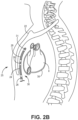
- FIG. 2B is a side view of patient 12 implanted with ICD system 10.
- FIG. 2C is a transverse view of patient 12 implanted with ICD system 10.
- lead 16 of system 10 is implanted at least partially underneath sternum 22 of patient 12. Lead 16 extends subcutaneously or submuscularly from ICD 14 toward xiphoid process 20 and at a location near xiphoid process 20 bends or turns and extends superiorly within anterior mediastinum 36 in a substernal position.
- Anterior mediastinum 36 may be viewed as being bounded laterally by pleurae 39, posteriorly by pericardium 38, and anteriorly by sternum 22. In some instances, the anterior wall of anterior mediastinum 30 may also be formed by the transversus thoracis muscle and one or more costal cartilages.
- Anterior mediastinum 36 includes a quantity of loose connective tissue (such as areolar tissue), adipose tissue, some lymph vessels, lymph glands, substernal musculature, small side branches of the internal thoracic artery or vein, and the thymus gland.
- the distal portion 25 of lead 16 extends along the posterior side of sternum 22 substantially within the loose connective tissue and/or substernal musculature of anterior mediastinum 36.
- a lead implanted such that the distal portion 25 is substantially within anterior mediastinum 36 may be referred to as a "substernal lead.”
- the distal portion 25 of lead body 18 is located substantially centered under sternum 22. In other instances, however, the distal portion 25 may be implanted such that it is offset laterally from the center of sternum 22. In some instances, lead 16 may extend laterally such that distal portion 25 is underneath/below the ribcage 32 in addition to or instead of sternum 22.
- the distal portion 25 of lead 16 may be implanted in other extra-cardiovascular, intra-thoracic locations, including the pleural cavity or around the perimeter of or adjacent to the pericardium 38 of heart 8.
- Other implant locations and lead and electrode arrangements that may be used in conjunction with the techniques described herein are generally disclosed in the incorporated patent references.
- FIG. 3 is a conceptual diagram illustrating a distal portion 25' of another example of extra-cardiovascular lead 16 of FIGs. 1A-2C having a curving distal portion 25' of lead body 18'.
- Lead body 18' may be formed having an undulating, curving, bending, serpentine, or zig-zagging shape along distal portion 25'.
- defibrillation electrodes 24' and 26' are carried along pre-formed curving portions of the lead body 18'.
- Pace/sense electrode 30' is carried in between defibrillation electrodes 24' and 26'.
- Pace/sense electrode 28' is carried proximal to the proximal defibrillation electrode 24'. No electrode is provided distal to defibrillation electrode 26' in this example.
- lead body 18' may be formed having a curving distal portion 25' that includes two "C" shaped curves, which together may resemble the Greek letter epsilon, " ⁇ .”
- Defibrillation electrodes 24' and 26' are each carried by one of the two respective C-shaped portions of the lead body distal portion 25', which extend or curve in the same direction away from a central axis 33 of lead body 18'.
- pace/sense electrode 28' is proximal to the C-shaped portion carrying electrode 24'
- pace/sense electrode 30' is proximal to the C-shaped portion carrying electrode 26'.
- Pace/sense electrodes 28' and 30' may, in some instances, be approximately aligned with the central axis 33 of the straight, proximal portion of lead body 18' such that mid-points of defibrillation electrodes 24' and 26' are laterally offset from electrodes 28' and 30'.
- Other examples of extra-cardiovascular leads including one or more defibrillation electrodes and one or more pacing and sensing electrodes carried by curving, serpentine, undulating or zig-zagging distal portion of the lead body that may be implemented with the pacing techniques described herein are generally disclosed in pending U.S. Pat. Publication No. 2016/0158567 (Marshall et al. ), incorporated herein by reference in its entirety.
- FIG. 4 is a schematic diagram of ICD 14 according to one example.
- the electronic circuitry enclosed within housing 15 includes software, firmware and hardware that cooperatively monitor one or more cardiac electrical signals, determine when an electrical stimulation therapy is necessary, and deliver therapy as needed according to programmed therapy delivery algorithms and control parameters.
- the software, firmware and hardware are configured to detect and discriminate VT and VF for determining when ATP or CV/DF shocks are required and may determine when bradycardia pacing, post-shock pacing, rate-responsive pacing or other types of electrical stimulation is needed.
- ICD 14 is coupled to an extra-cardiovascular lead, such as lead 16 carrying extra-cardiovascular electrodes 24, 26, 28, 30, and 31, as shown in FIG. 1A , for delivering electrical stimulation pulses to the patient's heart and for sensing cardiac electrical signals.
- ICD 14 includes a control circuit 80, memory 82, therapy delivery circuit 84, sensing circuit 86, and telemetry circuit 88.
- a power source 98 provides power to the circuitry of ICD 14, including each of the circuits 80, 82, 84, 86, and 88 as needed.
- Power source 98 may include one or more energy storage devices, such as one or more rechargeable or non-rechargeable batteries. The connections between power source 98 and each of the other circuits 80, 82, 84, 86 and 88 are to be understood from the general block diagram of FIG. 4 , but are not shown for the sake of clarity.
- power source 98 may be coupled to a low voltage (LV) charging circuit and to a high voltage (HV) charging circuit included in therapy delivery circuit 84 for charging low voltage and high voltage capacitors, respectively, included in therapy delivery circuit 84 for producing respective low voltage pacing pulses, such as bradycardia pacing, post-shock pacing or ATP pulses, or for producing relatively higher voltage pulses, such as CV/DF shock pulses or higher voltage pacing pulses.
- high voltage capacitors are charged and utilized for delivering pacing pulses instead of low voltage capacitors.
- the circuits shown in FIG. 4 represent functionality included in ICD 14 and may include any discrete and/or integrated electronic circuit components that implement analog and/or digital circuits capable of producing the functions attributed to ICD 14 herein.
- the various circuits may include one or more of an application specific integrated circuit (ASIC), an electronic circuit, a processor (shared, dedicated, or group) and memory that execute one or more software or firmware programs, a combinational logic circuit, state machine, or other suitable components or combination of components that provide the described functionality.
- ASIC application specific integrated circuit
- the particular form of software, hardware and/or firmware employed to implement the functionality disclosed herein will be determined primarily by the particular system architecture employed in the ICD and by the particular detection and therapy delivery methodologies employed by the ICD. Providing software, hardware, and/or firmware to accomplish the described functionality in the context of any modern IMD system, given the disclosure herein, is within the abilities of one of skill in the art.
- Memory 82 may include any volatile, non-volatile, magnetic, or electrical non-transitory computer readable storage media, such as a random access memory (RAM), read-only memory (ROM), non-volatile RAM (NVRAM), electrically-erasable programmable ROM (EEPROM), flash memory, or any other memory device. Furthermore, memory 82 may include non-transitory computer readable media storing instructions that when executed by one or more processing circuits, cause control circuit 80 and/or other ICD circuits to perform various functions attributed to ICD 14 or those ICD circuits. The non-transitory computer-readable media storing the instructions may include any of the media listed above.
- ICD 14 may be embodied as one or more integrated circuits. Depiction of different circuits is intended to highlight different functional aspects and does not necessarily imply that such circuits must be realized by separate hardware or software components. Rather, functionality associated with one or more circuits may be performed by separate hardware, firmware or software components, or integrated within common hardware, firmware or software components. For example, sensing operations may be performed by sensing circuit 86 under the control of control circuit 80 and may include operations implemented in a processor executing instructions stored in memory 82 and control signals such as timing and sensing threshold amplitude signals sent from control circuit 80 to sensing circuit 86.
- Control circuit 80 communicates, e.g., via a data bus, with therapy delivery circuit 84 and sensing circuit 86 for sensing cardiac electrical activity, detecting cardiac rhythms, and controlling delivery of cardiac electrical stimulation therapies in response to sensed cardiac signals.
- Therapy delivery circuit 84 and sensing circuit 86 are electrically coupled to electrodes 24, 26, 28, 30 and 31 (if present) carried by lead 16 and the housing 15, which may function as a common or ground electrode or as an active can electrode for delivering CV/DF shock pulses or cardiac pacing pulses.
- Sensing circuit 86 may be selectively coupled to electrodes 28, 30 and 31 and/or housing 15 in order to monitor electrical activity of the patient's heart. Sensing circuit 86 may additionally be selectively coupled to defibrillation electrodes 24 and/or 26 for use in a sensing electrode vector. Sensing circuit 86 is enabled to selectively monitor one or more sensing vectors at a time selected from the available electrodes 24, 26, 28, 30, 31 and housing 15. For example, sensing circuit 86 may include switching circuitry for selecting which of electrodes 24, 26, 28, 30, 31 and housing 15 are coupled to sense amplifiers or other cardiac event detection circuitry included in sensing circuit 86.
- Switching circuitry may include a switch array, switch matrix, multiplexer, or any other type of switching device suitable to selectively couple components of sensing circuit 86 to selected electrodes.
- control circuit 80 may control the switching circuitry to selectively couple sensing circuit 86 to one or more sense electrode vectors.
- the cardiac event detection circuitry within sensing circuit 86 may include one or more sense amplifiers, filters, rectifiers, threshold detectors, comparators, analog-to-digital converters (ADCs), or other analog or digital components.
- sensing circuit 86 includes multiple sensing channels for acquiring cardiac electrical signals from multiple sensing vectors selected from electrodes 24, 26, 28, 30, 31 and housing 15.
- Each sensing channel may be configured to amplify, filter and rectify the cardiac electrical signal received from selected electrodes coupled to the respective sensing channel to improve the signal quality for sensing cardiac events, such as R-waves.
- each sensing channel may include a pre-filter and amplifier for filtering and amplifying a signal received from a selected pair of electrodes.
- the resulting raw cardiac electrical signal may be passed from the pre-filter and amplifier to a post-filter and amplifier, analog-to-digital converter, rectifier, and cardiac event detector that compares the digitized, filtered and rectified cardiac electrical signal to a cardiac event sensing threshold for sensing cardiac events from the received cardiac electrical signal
- the cardiac event detector may include a sense amplifier, comparator or other detection circuitry that senses a cardiac event when the cardiac electrical signal crosses the cardiac event sensing threshold.
- the cardiac event sensing threshold is automatically adjusted by sensing circuit 86 under the control of control circuit 80, based on timing intervals and sensing threshold values determined by control circuit 80, stored in memory 82, and/or controlled by hardware of control circuit 80 and/or sensing circuit 86.
- Some sensing threshold control parameters may be programmed by a user and passed from control circuit 80 to sensing circuit 86 via a data bus.
- sensing circuit 86 may sense R-waves according to a sensing threshold that is automatically adjusted to multiple threshold levels at specified times after a sensing threshold crossing or after an electrical stimulation pulse delivered by therapy delivery circuit 84. Multiple threshold levels and the time intervals over which each threshold level or value is applied may be used to provide accurate R-wave sensing while minimizing T-wave oversensing and P-wave oversensing. If T-waves and/or P-waves are falsely sensed as R-waves, due to a cardiac electrical signal crossing the R-wave sensing threshold, a tachyarrhythmia may be falsely detected potentially leading to an unnecessary cardiac electrical stimulation therapy, such as ATP or shock delivery.
- This situation is avoided using the multi-level sensing threshold techniques disclosed herein while still providing VT and VF detection with a high sensitivity. Oversensing may also cause ICD 14 to inhibit bradycardia pacing pulses when pacing is actually needed. By avoiding oversensing using the multi-level sensing threshold, inhibiting of bradycardia pacing pulses when pacing is actually needed is avoided.
- sensing circuit 86 may produce a sensed event signal, such as an R-wave sensed event signal, that is passed to control circuit 80.
- the sensed event signals are used by control circuit 80 for detecting cardiac rhythms and determining a need for therapy. For example, time intervals between consecutive sensed event signals may be determined and compared to tachyarrhythmia detection intervals for detecting a tachyarrhythmia and thereby determine a need for an electrical stimulation therapy to treat the detected tachyarrhythmia.
- Sensing circuit 86 may also pass a digitized electrocardiogram (ECG) signal to control circuit 80 for morphology analysis performed for detecting and discriminating heart rhythms. In some examples, analysis of the digitized cardiac electrical signal is performed for determining R-wave sensing threshold control parameters as described in conjunction with FIG. 11 .
- ECG electrocardiogram
- Signals from the selected sensing vector may be passed through a bandpass filter and amplifier, provided to a multiplexer and thereafter converted to multi-bit digital signals by an analog-to-digital converter, all included in sensing circuit 86, for storage in random access memory included in memory 82 under control of a direct memory access circuit via a data/address bus.
- Control circuit 80 may be a microprocessor based controller that employs digital signal analysis techniques to characterize the digitized signals stored in random access memory of memory 82 to recognize and classify the patient's heart rhythm employing any of numerous signal processing methodologies for analyzing cardiac signals and cardiac event waveforms, e.g., R-waves.
- Examples of algorithms that may be performed by ICD 14 for detecting, discriminating and treating tachyarrhythmia which may be adapted to utilize techniques disclosed herein for controlling a multi-level cardiac event sensing threshold for sensing cardiac electrical signals are generally disclosed in U.S. Pat. No. 5,354,316 (Keimel ); U.S. Pat. No. 5,545,186 (Olson, et al. ); U.S. Pat. No. 6,393,316 (Gillberg et al. ); U.S. Pat. No. 7,031,771 (Brown, et al. ): U.S. Pat. No. 8,160,684 (Ghanem, et al. ), and U.S. Pat. No. 8,437,842 (Zhang, et al. ), all of which patents are incorporated herein by reference in their entirety.
- Therapy delivery circuit 84 includes charging circuitry, one or more charge storage devices, such as one or more high voltage capacitors and in some examples one or more low voltage capacitors, and switching circuitry that controls when the capacitor(s) are discharged across a selected pacing electrode vector or CV/DF shock vector. Charging of capacitors to a programmed pulse amplitude and discharging of the capacitors for a programmed pulse width may be performed by therapy delivery circuit 84 according to control signals received from control circuit 80. Control circuit 80 may include various timers or counters that control when ATP or other cardiac pacing pulses are delivered.
- control circuit 80 may include pacer timing and control circuitry having programmable digital counters set by the microprocessor of the control circuit 80 for controlling the basic time intervals associated with various pacing modes or anti-tachycardia pacing sequences delivered by ICD 14.
- the microprocessor of control circuit 80 may also set the amplitude, pulse width, polarity or other characteristics of the cardiac pacing pulses, which may be based on programmed values stored in memory 82.
- escape interval counters within the pacer timing and control circuitry are reset upon sensing of an intrinsic R-wave as indicated by an R-wave sensed event signal from sensing circuit 86 and upon generation of a pacing pulse
- pacing pulses are generated by a pulse output circuit of therapy delivery circuit 84 if an escape interval expires without being reset due to an R-wave sensed event signal.
- the pace output circuit is coupled to the desired electrodes via switch matrix for discharging one or more capacitors across the pacing load.
- the durations of the escape intervals are determined by control circuit 80 via a data/address bus.
- sensing circuit 86 may be configured to control the R-wave sensing threshold used for sensing R-waves from a received cardiac electrical signal according to post-sense control parameters and according to post-pulse control parameters
- One or more time intervals and/or sensing threshold values used to control the R-wave sensing threshold following an electrical stimulation pulse e.g., a pacing pulse or CV/DF shock pulse, may be different than the time intervals and/or sensing threshold values used to control the R-wave sensing threshold following a sensed intrinsic R-wave.
- Memory 82 includes read-only memory (ROM) in which stored programs controlling the operation of the control circuit 80 reside. Memory 82 may further include random access memory (RAM) configured as a number of recirculating buffers capable of holding a series of measured intervals, counts or other data for analysis by the control circuit 80 for predicting or diagnosing an arrhythmia.
- ROM read-only memory
- RAM random access memory
- ATP therapy can be delivered by loading a regimen from the microprocessor included in control circuit 80 into the pacer timing and control circuit according to the type and rate of tachycardia detected.
- the control circuit microprocessor activates cardioversion and defibrillation control circuitry included in control circuit 80 to initiate charging of the high voltage capacitors of via a charging circuit, both included in therapy delivery circuit 84, under the control of a high voltage charging control line. The voltage on the high voltage capacitors is monitored via a voltage capacitor line, which is passed to control circuit 80.
- a logic signal is generated on a capacitor full line passed to therapy delivery circuit 84, terminating charging.
- the CV/DF pulse is delivered to the heart by an output circuit of therapy delivery circuit 84 under the control of the pacer timing and control circuitry via a control bus.
- the output circuit determines the electrodes used for delivering the CV/DF pulse and the pulse wave shape.
- Therapy delivery and control circuitry generally disclosed in any of the above-incorporated patents may be implemented in ICD 14.
- Control parameters utilized by control circuit 80 for detecting cardiac rhythms and controlling therapy delivery may be programmed into memory 82 via telemetry circuit 88.
- Telemetry circuit 88 includes a transceiver and antenna for communicating with external device 40 (shown in FIG. 1A ), e.g., using RF communication as described above. Under the control of control circuit 80, telemetry circuit 88 may receive downlink telemetry from and send uplink telemetry to extemal device 40. In some cases, telemetry circuit 88 may be used to transmit and receive communication signals to/from another medical device implanted in patient 12.
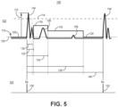
- FIG. 5 is a timing diagram 100 showing a band-pass filtered and rectified cardiac electrical signal 102 and R-wave sensed event signals 103 produced by sensing circuit 86.
- the cardiac electrical signal 102 includes R-waves 104, 104', T-wave 106, and P-wave 108.
- R-wave sensing generally refers to sensing the intrinsic QRS complex of a cardiac electrical signal for the purposes of detecting and discriminating intrinsic ventricular rhythms, e.g., for detecting and discriminating ventricular fibrillation, ventricular tachycardia, supraventricular tachycardia, bradycardia, asystole or other types of intrinsic heart rhythms.
- Sensing circuit 86 automatically adjusts an R-wave sensing threshold 110 to multiple threshold values 116, 118, and 120.
- the multiple threshold values 116, 118, and 120 may be determined by control circuit 80 based on the maximum peak amplitude 112 of a sensed R-wave 104 and passed to sensing circuit 86 along with multiple timing intervals 130, 132, 134 and 136 for controlling the R-wave sensing threshold 110 for detecting of the next R-wave 104'.
- Threshold values 116, 118 and 120 of R-wave sensing threshold 110 may also be referred to as threshold “levels” or “settings” or merely as “thresholds” but all refer to different voltage amplitudes which, when crossed by a positive-going, rectified band-pass filtered cardiac electrical signal, result in an R-wave sensed event signal being produced by sensing circuit 86.
- R-wave 104 is sensed by sensing circuit 86 when the cardiac electrical signal 102 crosses R-wave sensing threshold 110, which is set to threshold value 120 at the time of the threshold crossing.
- An R-wave sensed event signal 150 is generated.
- a post-sense blanking interval 130 may be started.
- the post-sense blanking interval may be a fixed time interval controlled by hardware that prevents the R-wave 104 from being sensed twice.
- the post-sense blanking interval 130 is 120 ms in one example, and may be 120 ms to 160 ms in other examples.
- a peak detector circuit included in sensing circuit 86 or control circuit 80 determines the maximum peak amplitude 112 of R-wave 104.
- the maximum peak amplitude 112 is used to determine the sensing threshold values 116 and 118.
- a second blanking interval 132 is started upon sensing R-wave 104 and is slightly longer than the first blanking interval 130.
- a microprocessor within control circuit 80 may fetch the R-wave peak amplitude and determine the first, starting threshold value 116 prior to expiration of the second blanking interval 132.
- the R-wave sensing threshold 110 may be set to the starting threshold value 116 upon expiration of the second blanking interval 132.
- the second blanking interval 132 may be at least 20 ms longer than the first blanking interval 130.
- second blanking interval 132 may be 140 ms to 180 ms long in some examples.
- the first blanking interval 130 is a hardware controlled blanking interval
- the second blanking interval 132 is a digital blanking interval controlled by firmware or software stored in memory 82.
- the second blanking interval 132 may be a user-programmable value so that it may be tailored to the patient, e.g., based on the width of R-wave 104.
- the control circuit 80 may determine the first, starting threshold value 116 as a percentage of the R-wave peak amplitude 112 during the interval between the expiration of the first blanking interval 130 and the expiration of the second blanking interval 132. This interval difference between the first and second blanking intervals 130 and 132 may be minimized in some examples to enable firmware processing time to determine the first, starting threshold value 116 but enable R-wave sensing as early as possible after expiration of the first blanking interval 130.
- the multi-level R-wave sensing threshold 110 disclosed herein may be implemented in many existing IMD systems that already include a hardware-implemented blanking interval without requiring hardware modifications.
- the longer second blanking interval 132 may be fixed or programmable to account for wider R-waves that typically appear in a cardiac signal obtained using extra-cardiovascular electrodes compared to the R-wave width in intracardiac electrogram signals.
- the second blanking interval 132 as a digital blanking interval allows R-wave sensing threshold control techniques disclosed herein to operate in conjunction with other algorithms or methods being executed by hardware or firmware of ICD 14 for heart rhythm detection without modification.
- ICD 14 may be configured to execute T-wave oversensing rejection algorithms implemented in hardware or firmware configured to determine a differential filtered cardiac electrical signal as generally disclosed in U.S. Pat. No. 7,831,304 (Cao, et al. ), incorporated herein by reference in its entirety.
- the R-wave sensing threshold 110 may be controlled without altering operations performed by a T-wave oversensing rejection algorithm operating concurrently, which may be implemented in hardware.
- the first blanking interval 130, peak detector for determining R-wave peak amplitude 112, and the second blanking interval 132 may all be implemented in hardware, all be implemented in firmware or a combination of both.
- the second blanking interval 132 may be programmable such that the time of the onset of R-wave sensing at the expiration of the second blanking interval 132, after the expiration of the first blanking interval 130, may be selected by a user according to patient need.
- peak detection and determination of the starting threshold value 116 are implemented in hardware, a single hardware implemented blanking interval 130 may be used without requiring a second blanking interval 132 for providing firmware processing time during which the starting threshold value 116 is determined.
- the first sensing threshold value 116 may set to a percentage of the R-wave peak amplitude 112.
- the first sensing threshold value 116 may be 50% of peak amplitude 112, and may be from 40% to 60% in other examples.
- the percentage of R-wave peak amplitude 112 used to determine the starting threshold value 116 is selected to promote a high likelihood that the threshold value 116 is greater than the maximum amplitude of T-wave 106.
- the percentage of peak amplitude 112 used to determine starting threshold value 116 may be selected based on a previous baseline T-wave amplitude measurement or T/R amplitude ratio.
- the starting threshold value 116 is held constant over a sense delay interval 134 in the example shown to maintain the R-wave sensing threshold 110 above a maximum T-wave amplitude until a time point near the end or after the T-wave 106.
- the R-wave sensing threshold 110 may have a starting threshold value 116 that slowly decays over the sense delay interval 134. The decay rate, however, is selected to be relatively slow so that the ending threshold value at the expiration of the sense delay interval 134 is still greater than an expected T-wave amplitude.
- Sense delay interval 134 may be started upon sensing R-wave 104, as shown in FIG. 5 . Alternatively, sense delay interval 134 may be started upon expiration of the second blanking interval 132. Sense delay interval 134 may be a user-programmable interval which may be tailored to patient need to encompass the T-wave 106, or at least the peak of the T-wave or a majority of the T-wave 106, to avoid T-wave oversensing. Sense delay interval 134 is 360 ms in one example and may be, with no limitation intended, 300 ms to 400 ms in other examples.
- the user By allowing a user to program the sense delay interval 134, the user has the ability to make adjustments to how early after a sensed R-wave the sensing threshold 110 is adjusted to a lower value, e.g., threshold value 118.
- a lower value e.g., threshold value 118.
- the clinician has the ability to increase the sense delay interval 134 to avoid future T-wave oversensing without compromising detection of ventricular fibrillation or ventricular tachycardia.
- Control circuit 80 may be configured to detect T-wave oversensing when it occurs and reject RR-intervals or other evidence of VT or VF when T-wave oversensing is detected.
- T-wave oversensing rejection algorithms that may be included in ICD 14 are generally disclosed in the above-incorporated '304 patent (Cao, et al.) and in U.S. Pat. No. 8,886,296 (Patel, et al. ) and U.S. Pat. No. 8,914,106 (Charlton, et al. ), also incorporated herein by reference in their entirety.
- control circuit 80 may automatically increase the sense delay interval 134 and/or increase the starting value 116 of R-wave sensing threshold 110 in response to T-wave oversensing detection.
- Sense delay interval 134 may be increased up to a predefined maximum limit, e.g., 440 ms. If there is no TWOS detected for a predetermined time interval, for example one minute one hour or one day, or if a tachyarrhythmia episode is being detected (e.g., three or more VT or VF intervals detected), sense delay interval 134 may be automatically reduced to a shorter interval or to a previous setting by control circuit 80.
- sense delay interval 134 is set equal to the tachycardia detection interval (TDI) used by control circuit 80 for detecting ventricular tachycardia (VT).
- sense delay interval 134 may be set slightly longer than the TDI, e.g., 10 to 20 ms longer than the TDI.
- Intervals between consecutively sensed R-wavces, for example RR interval 140 between two consecutive R-wave sensed event signals 150 and 152 shown in FIG. 5 are compared to the TDI and to a fibrillation detection interval (FDI) by a cardiac rhythm analyzer included in control circuit 80. If an RR, interval is less than the TDI, the cardiac rhythm analyzer may increase a VT interval counter.
- TDI tachycardia detection interval
- VT ventricular tachycardia
- the cardiac rhythm analyzer may increase a VF interval counter. If the VT counter reaches a number of intervals to detect (NID) VT, VT is detected. If the VF counter reaches an NID to detect VF, VF is detected.
- NID intervals to detect
- the R-wave sensing threshold 110 is kept high, at the starting threshold value 116, throughout the FDI and the TDI (which is longer than the FDI) such that the likelihood of a falsely sensed R-wave due to T-wave oversensing during the TDI is minimized, minimizing the likelihood of an oversensed T-wave contributing to a VT or VF detection.
- the sense delay interval 134 may be set to match the TDI programmed for VT detection and may be automatically adjusted to track the TDI if the TDI is reprogrammed to a different value.
- the sensing circuit 86 adjusts R-wave sensing threshold 110 to a second threshold value 118, lower than the starting value 116.
- the second threshold value 118 may be determined as a percentage of the R-wave peak amplitude 112. In one example, threshold value 118 is set to approximately 28% of the R-wave peak amplitude 112. Threshold value 118 may be set to 20% to 30% of the R-wave peak amplitude 112 in other examples.
- the second threshold value 118 is set to a value that is expected to be greater than the peak amplitude of the P-wave 108.
- P-waves are generally much lower in amplitude than R-waves, however, depending on the alignment of the sensing electrode vector relative to the cardiac axis and other factors, P-wave oversensing can occur in some patients, particularly when the lead 16 is positioned substemally as shown in FIG. 2A .
- R-wave sensing threshold 110 is held at the second threshold value 118 until the expiration of drop time interval 136.
- Drop time interval 136 may be started at the time R-wave 104 is sensed, as shown in FIG. 5 , or upon expiration of blanking interval 130, blanking interval 132, or sense delay interval 134.
- drop time interval 136 When drop time interval 136 is started upon sensing R-wave 104, it may be set to 1.5 seconds or other relatively long interval to promote a high likelihood of maintaining the R-wave sensing threshold at the second value 118 until after P-wave 108, or at least until after the peak amplitude or majority of P-wave 108, Drop time interval 136 may be a fixed interval or may be programmable by the user.
- the drop time interval 136 may range from 0.8 to 2.0 seconds in other examples.
- the drop time interval 136 may be adjusted with changes in heart rate. For example, as heart rate increases based on measurements of RR intervals such as RR interval 140, the drop time interval 136 may be shortened. As heart rate decreases, the drop time interval 136 may be increased.
- the R-wave sensing threshold 110 is adjusted from the second sensing threshold value 118 to a minimum sensing threshold value 120, which may be referred to as the "sensing floor.”
- the R-wave sensing threshold 110 remains at the minimum sensing threshold 120 until the cardiac electrical signal 102 crosses the threshold 120.
- R-wave 104' is sensed when the minimum sensing threshold 120 is crossed, causing sensing circuit 86 to generate R-wave sensed event signal 152.
- the minimum sensing threshold value 120 is set equal to the programmed sensitivity setting 122 which may be, for example, 0.07 millivolts (mV), 0.15 mV, 0.3 mV, 0.6 mV or higher.
- the programmed sensitivity setting 122 may establish the minimum possible sensing threshold value in some examples, in which case the R-wave sensing threshold 110 is never set below the programmed sensitivity setting 122.
- the sensitivity setting 122 may be programmable between 0.075 and 1.2 millivolts (mV) in one example and may be selected by a user as the minimum voltage threshold required to sense a cardiac event from cardiac signal 102. As the value of the sensitivity setting 122 decreases, sensitivity of the sensing circuit for sensing low amplitude signals increases.
- a low sensitivity setting 122 corresponds to high sensitivity for sensing R-waves.
- the lowest setting e.g., 0.07 mV
- the highest setting e.g., 1.2 mV
- Pulses of the cardiac electrical signal 102 that have a maximum peak voltage below the programmed sensitivity setting 122 are considered noise or events that are not intended to be sensed, which may include T-waves and P-waves.
- the user may reprogram the sensitivity setting 122 to a higher setting (lower sensitivity).
- the programmed sensitivity setting 122 may be kept at a low value to provide high sensitivity for sensing R-waves and low amplitude fibrillation waves while still minimizing the likelihood of T-wave and P-wave oversensing.
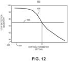
- control circuit 80 may establish a maximum R-wave sensing threshold limit 114 that limits the maximum starting value of R-wave sensing threshold 110. If the starting value 116 of the R-wave sensing threshold 110 determined based on peak amplitude 112 of R-wave 104 is greater than the maximum threshold limit 114, the starting value of R-wave sensing threshold 110 may be set to the maximum threshold limit 114. In some cases, a maximum R-wave sensing threshold limit 114 is set as a fixed multiple or fixed gain of the programmed sensitivity setting 122, for example a gain of eight to ten times the sensitivity setting 122. In other examples, the gain applied to the programmed sensitivity setting 122 for establishing a maximum R-wave sensing threshold limit 114 is a variable gain. The variable gain may be defined to be dependent on the programmed sensitivity setting 122 as described below.
- FIG. 6 is a diagram of a filtered and rectified cardiac electrical signal 200 including R-wave 202 and T-wave 204.
- Two examples of maximum R-wave sensing threshold limits 216 and 218 are each set as a fixed multiple of a respective programmed sensitivity setting 220 or 222. As can be seen in this example, in some cases, when large amplitude R-waves and T-waves occur, the maximum R-wave sensing threshold limit 218 set as a fixed multiple of the lower programmed sensitivity setting 222 may result in T-wave oversensing because T-wave 204 crosses the maximum R-wave sensing threshold limit 218.
- the maximum peak amplitude 212 of R-wave 202 is 10 mV, and the sensitivity setting 222 is programmed to 0.3 mV.
- the maximum R-wave sensing threshold limit 218 is set to 3 mV, when a fixed gain of 10 times the programmed sensitivity setting is used to set the maximum threshold limit 218.
- the first sensing threshold value 214 determined as a percentage (50% in the example shown) of the maximum peak amplitude 212 of the R-wave 202 is greater than the maximum sensing threshold limit 218.
- the R-wave sensing threshold is set to the maximum sensing threshold limit 218 at the expiration of the second blanking interval 132 until the expiration of sense delay interval 134.
- the R-wave sensing threshold set to the maximum threshold limit 218 would result in T-wave oversensing in this example since the maximum limit 218 is less than the amplitude of T-wave 204.
- a higher sensitivity setting 220 could be programmed, for example 0.6 mV.
- the maximum sensing threshold limit 216 is 6 mV in the example of the programmed sensitivity setting 220 being 0.6 mV and a fixed gain of 10 being used to determine the maximum limit 216.
- This maximum threshold limit 216 is greater than the starting sensing threshold value 214 determined as a percentage of R-wave amplitude peak 212, which is 50% of 10 mV or 5 mV in this example.
- This starting threshold value 214 is applied as the R-wave sensing threshold upon expiration of the second blanking interval 132 since it is less than the maximum threshold limit 216.
- the starting threshold value 214 does not result in T-wave oversensing because the amplitude of T-wave 204 is less than the starting sensing threshold value 214.
- T-wave oversensing can occur when a maximum sensing threshold limit is determined as a fixed gain of the sensitivity setting and the sensitivity setting is low.
- the sensitivity setting can be increased to lower the sensitivity, e.g., to 0.6 mV from 0.3 mV as represented by sensitivity setting 220 and sensitivity setting 222, respectively, in FIG. 6 .
- the higher sensitivity setting makes sensing circuit 86 less sensitive to low amplitude R-waves that may occur during VT or VF, potentially resulting in under-detection of ventricular tachyarrhythmia episodes.
- FIG. 7 is a diagram of the cardiac electrical signal 200 shown in FIG. 6 shown with two different examples of maximum sensing threshold limits 256 and 258 determined using a variable, sensitivity-dependent gain applied to the programmed sensitivity.
- the gain or multiple of the programmed sensitivity setting used by control circuit 80 to determine the maximum sensing threshold limit following a sensed event is a function of the programmed sensitivity setting in some examples.
- the maximum sensing threshold limit may be inversely related to the programmed sensitivity setting such that a higher gain is applied to a lower programmed sensitivity setting for obtaining the maximum threshold limit.
- G variable gain
- a and B are constants
- S the programmed sensitivity (B/S being an inverse proportion of the programmed sensitivity setting).
- the gain determined for each available programmable sensitivity setting is stored in a look-up table in memory 80 and is retrieved by control circuit 80 each time a new sensitivity setting is programmed.
- A is at least 5 and B is at least 1.5.
- B may be equal to 2.5 in the equation given for the gain G above.
- the minimum possible value of the maximum sensing threshold limit will approach 2.5 since the maximum sensing threshold limit is the product of the gain and the programmed sensitivity setting, or 6S + 2.5 where S equals the programmed sensitivity setting.
- the sensitivity-dependent gain ranges from approximately 39.3 for the lowest sensitivity setting of 0.075 mV (corresponding to highest sensitivity) to approximately 8.1 for the highest sensitivity setting of 1.2 mV (corresponding to the lowest sensitivity). The higher the sensitivity, i.e., the lower the sensitivity setting, the higher the sensitivity-dependent gain is.
- the maximum sensing threshold limit 258 determined when the sensitivity setting 222 is programmed to 0.3 mV is the sensitivity-dependent gain, 14.3, multiplied by the sensitivity setting, 0.3 mV, or approximately 4.3 mV. This maximum sensing threshold limit 258 is less than the first sensing threshold value 254 determined as a percentage (50% in this example) of R-wave peak amplitude 212.
- the R-wave sensing threshold 210 will be set to the maximum sensing threshold limit 258, but in this case the sensing threshold limit 258 set using the variable gain is greater than the amplitude of T-wave 204, thereby avoiding T-wave oversensing while still allowing a high sensitivity (low sensitivity setting) to be used for sensing low amplitude waveforms during VT or VF (especially spontaneous fine VF) after the drop time interval 134 expires.
- the R-wave sensing threshold value during the sense delay interval 134 avoids T-wave oversensing in the presence of large amplitude R-waves and T-waves. Even when a low sensitivity setting is used.. e.g., 0.3 mV or less, so that sensing circuit 86 remains highly sensitive to small R-waves that may occur during a ventricular tachyarrhythmia, T-wave oversensing is avoided by using a sensitivity-dependent variable gain for determining the maximum R-wave sensing threshold limit.
- the R-wave sensing threshold is adjusted from the starting threshold 254 or 258, to the second threshold 260 which is determined as 25% of the R-wave peak amplitude 212 in this example.
- the second threshold 260 remains in effect until the drop time interval 136 expires (described in FIG. 5 ) after which the R-wave sensing threshold 210 drops to the programmed sensitivity setting, either the 0.6 mV sensitivity setting 220 or the 0.3 mV sensitivity setting 222 in the example shown in FIG. 7 .
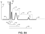
- FIG. 8A is a diagram of a filtered and rectified cardiac electrical signal 300 including an R-wave 302, a T-wave 304, and a P-wave 306 and an automatically adjusted R-wave sensing threshold 310 having multiple sensing threshold values 316, 317, 318 and 320.
- the R-wave sensing threshold 310 is set to the first, starting threshold value and second threshold value before dropping to the programmed sensitivity setting. In other examples, the R-wave sensing threshold 310 may be adjusted to three or more threshold values before dropping to the programmed sensitivity setting.
- the starting threshold value 316 may be determined as a first percentage of the peak R-wave amplitude 312 that is detected during first blanking interval 330, e.g, 62.5% or between 55% and 70% of the peak R-wave amplitude 312.
- the starting threshold value 316 may be maintained from the expiration of the second blanking interval 332 until the expiration of a first sense delay interval 333.
- the first sense delay interval 333 may be approximately 180 ms, for example 30 to 60 ms longer than the second blanking interval 332.
- the higher starting threshold value 316 applied for a short interval may reduce the likelihood of double sensing the R-wave 302, particularly in patients exhibiting a wide QRS complex.
- the R-wave sensing threshold 310 Upon expiration of the first sense delay interval 333, the R-wave sensing threshold 310 is adjusted to a lower, second sensing threshold value 317, which may be between 30% and 60% of the R-wave peak amplitude 312, such as 50% of the R-wave peak amplitude 312.
- the second sensing threshold value 317 is maintained until expiration of the second sense delay interval 334, which may be between 300 and 360 ms, and may be set equal to a programmed TDI as described previously in conjunction with FIG. 5 .
- the third sensing threshold value 318 is applied until a drop time interval 336 expires, and the R-wave sensing threshold 310 falls to a minimum sensing threshold value 320, which may be equal to the programmed sensitivity setting.
- the third sensing threshold value 318 may be approximately 28% of the R-wave peak amplitude 312, or between 20% and 30% in other examples, and extend for a drop time interval 336 of one to two seconds, e.g., 1.5 seconds,
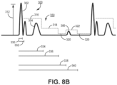
- FIG. 8B is a diagram of a non-monotonic, multi-level R-wave sensing threshold 350 accordmg to another example.
- R-wave sensing threshold 110 and R-wave sensing threshold 310 are monotonically decreasing sensing thresholds.
- the multi-level R-wave sensing threshold controlled by control circuit 80 is non-monotonic, including one or more step increases in the value of R-wave sensing threshold in addition to the decreasing step changes in the R-wave sensing threshold value.
- R-wave sensing threshold 350 may include a starting sensing threshold value 316 beginning upon expiration of second blanking interval 332 and a second sensing threshold value 318 beginning after expiration of the sense delay interval 334. R-wave sensing threshold 350 drops to the programmed sensitivity setting 320 upon expiration of drop time interval 336.
- the R-wave sensing threshold 350 is increased to a third sensing threshold value 322.
- the third sensing threshold value may be equal to the second sensing threshold value 318 or set as a percentage of a previously determined baseline P-wave maximum peak amplitude, e.g., 1.5 times a previously determined P-wave maximum peak amplitude.
- the maximum sensitivity interval 338 controls how long the R-wave sensitivity threshold 350 is held at the maximum sensitivity, e.g., the programmed sensitivity setting 320, before being increased to the third sensing threshold value 322
- the maximum sensitivity interval 338 is approximately 200 ms longer than the drop time interval 336 so that the R-wave sensing threshold 350 is set to the programmed sensitivity setting 320 for up to 200 ms if an R-wave sensing threshold crossing does not occur
- R-wave sensing threshold 350 Upon expiration of the maximum sensitivity interval 338, R-wave sensing threshold 350 is increased to the third sensing threshold value 322 to minimize the likelihood of oversensing the P-wave 306 during very slow heart rates and when the P-wave 306 has an amplitude greater than the programmed sensitivity setting 320, By allowing the R-wave sensing threshold 350 to drop to the programmed sensitivity setting 320, to provide high sensitivity for up to a predefined time interval as controlled by interval 338, undersensing of low amplitude, fine VF waveforms is avoided. Sensing circuit 86 may sense low amplitude ventricular tachyarrhythmia waveforms after expiration of drop time interval 336 and before expiration of maximum sensitivity interval 338.
- P-wave oversensing may be avoided by increasing the R-wave sensing threshold 350 to the third threshold value 322 while still providing an interval of high sensitivity to low amplitude tachyarrhythmia waveforms.
- the third sensing threshold value 322 may be maintained until a sensing threshold crossing occurs. In other examples, as shown in FIG. 8B , the third sensing threshold value 322 is held until a second drop time interval 340 expires, at which time the R-wave sensing threshold 350 is adjusted back to the programmed sensitivity setting 320.
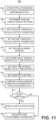
- FIG. 9 is a flow chart 400 of a method for controlling the R-wave sensing threshold according to one example.
- the control circuit 80 establishes the maximum threshold limit.
- the maximum threshold limit may be set based on a sensitivity-dependent gain as described in conjunction with FIG. 7 .
- Control circuit 80 determines the sensitivity-dependent gain then computes the maximum threshold limit as the product of the gain and the programmed sensitivity setting.
- the maximum threshold limit may be set as a fixed multiple of the programmed sensitivity setting, using a gain that is independent of the programmed sensitivity, as described in conjunction with FIG. 6 .
- the maximum threshold limit is re-established at block 402 each time the sensitivity is reprogrammed to a different sensitivity setting.
- an R-wave is sensed in response to the cardiac electrical signal crossing the R-wave sensing threshold, which may initially be set to the maximum sensing threshold, a nominal sensing threshold, the programmed sensitivity setting or other starting value.
- sensing circuit 86 produces an R-wave sensed event signal at block 408, and control circuit 80 sets various timers or counters as described in conjunction with FIGs. 5 and 8A and 8B for controlling the multi-threshold R-wave sensing threshold.
- a first blanking interval which may be a hardware controlled blanking interval
- a second blanking interval which may be a digital blanking interval controlled by firmware stored in memory 82
- a sense delay interval for example, a pulse width interval, a pulse width interval, and a pulse width interval.
- a maximum sensitivity interval may be started upon sensing an R-wave due to a positive-going R-wave sensing threshold crossing of the cardiac electrical signal received by sensing circuit 86
- the maximum peak amplitude of the sensed R-wave is determined during the first post-sense blanking interval.
- the R-wave peak amplitude may be determined by a peak track and hold circuit or other hardware or firmware.
- the R-wave peak amplitude is fetched by control circuit 80 at the expiration of the first post-sense blanking interval
- Control circuit 80 determines the starting and second threshold values at block 410 is two different percentages of the R-wave peak amplitude.
- the starting threshold value may be determined as 40 to 60% of the R-wave peak amplitude
- the second threshold value may be determined as 20 to 30% of the R-wave peak amplitude.
- Control circuit 80 may execute firmware after expiration of the first blanking interval for determining the starting, first threshold value and the second threshold value before expiration of the second blanking interval.
- the starting and second threshold values may be passed to sensing circuit 86 as control values used by circuitry of sensing circuit 86 for controlling the R-wave sensing threshold. In other examples, three or more threshold values are determined as described in conjunction with FIGs. 8A and 8B .
- the sensing circuit 86 Upon expiration of the second blanking interval, as determined at block 412, the sensing circuit 86 sets the starting R-wave sensing threshold at block 414 to the starting threshold value determined as a percentage of the R-wave peak amplitude or to the maximum threshold limit, whichever is less, under the control of control circuit 80. If the cardiac electrical signal crosses the starting R-wave sensing threshold, as determined at block 416, the process returns to block 406 where sensing circuit 86 produces another R-wave sensed event signal and restarts the various control time intervals as described above, e.g., first post-sense blanking interval 130, second post-sense blanking interval 132, sense delay interval 134 and drop time interval 136 shown in FIG. 5 .
- sensing circuit 86 adjusts the R-wave sensing threshold at block 420 to the second threshold value received from control circuit 80. If the cardiac electrical signal crosses the R-wave sensing threshold adjusted to the second threshold value, as determined at block 422, the process returns to block 406 to generate an R-wave sensed event signal and reset the control time intervals as described above. If the drop time interval expires at block 424 without the cardiac electrical signal crossing the R-wave sensing threshold (block 422), the sensing circuit 86 adjusts the R-wave sensing threshold to the minimum threshold value or sensing floor, which may be the programmed sensitivity setting, at block 426. In other examples, more than two drop steps in the sensing threshold value may be implemented, as described in conjunction with FIG. 8A , and/or a step increase in the sensing threshold value may be included as described in conjunction with FIG. 8B .
- Sensing circuit 86 waits for the cardiac electrical signal to cross the sensing floor at block 404 and the process repeats by advancing to block 406 if the cardiac electrical signal crosses the sensing floor. If a cardiac electrical stimulation therapy is enabled, however, for example a cardiac pacing therapy, the control circuit 80 may start a pacing interval at block 406 when various timers are set in response to the R-wave sensed event signal. If the pacing interval expires at block 430 before the cardiac electrical signal crosses the R-wave sensing threshold, control circuit 80 may advance to block 756 of FIG. 15 , described below, to deliver a cardiac pacing pulse and control the R-wave sensing threshold according to post-pace R-wave sensing control parameters.
- control parameters used to control the R-wave sensing threshold following an electrical stimulation pulse may be different than the post-sense R-wave sensing threshold control parameters described in conjunction with FIGs. 5-9 .
- Examples of post-pulse R-wave sensing threshold control parameters are described in conjunction with FIGs. 14-16 below.
- a maximum P-wave sensing threshold limit may be set based on a sensitivity-dependent gain and a programmed sensitivity; a maximum T-wave sensing threshold limit may be set based on a sensitivity-dependent gain and programmed sensitivity.
- P-wave and/or T-wave sensing thresholds may be controlled using multiple threshold levels and multiple time intervals.
- FIG. 10 is a flow chart of a method for selecting a sensitivity setting in ICD 14.
- the process shown in FIG. 10 may be performed at the time of ICD 14 implant or during a lead replacement procedure to determine a reliable sensitivity setting for detecting low amplitude fibrillation waves during VF.
- the process shown by flow chart 500 may be a semi-automated process executed by ICD 14 in response to programming commands received from external device 40.
- a test sensitivity setting is selected.
- the test sensitivity setting may be programmed by a user using external device 40 or may be a value two times a nominal sensitivity setting or a preferred sensitivity setting, which may be based on a measured R-wave amplitude. For example, if the R-wave amplitude observed on an electrocardiogram signal produced by ICD 14 and transmitted to external device 40 is at least 3 mV, a test sensitivity setting of 0.6 mV may be set at block 502 for a preferred sensitivity setting of 0.3 mV, half of the test setting.
- This process may be repeated one or more times as needed to determine the highest sensitivity setting that allows successful detection of VF.
- a recording of the cardiac electrical signal during the induced VF may be used to determine the voltage amplitude of the VF waveforms, and the sensitivity setting may be programmed lower than the VF waveform amplitude at block 512.
- sensing circuit 86 includes two sensing channels, the cardiac electrical signal may be sensed using two different test sensitivity settings simultaneously to determine if one or both result in VF detection.
- the sensitivity setting When VF is detected at the current test sensitivity setting the sensitivity setting is programmed to one-half to one-third the test sensitivity setting. For example, if the sensitivity setting tested is 0.6 mV, the sensitivity setting is programmed to 0.3 mV at block 512.
- a sensitivity-dependent gain for setting the maximum R-wave sensing threshold limit By using a sensitivity-dependent gain for setting the maximum R-wave sensing threshold limit, a lower sensitivity setting may be used with confidence in avoiding T-wave and P-wave oversensing while still providing high sensitivity for detecting VF, both acutely and chronically after implantation of the ICD system 10.
- the R-wave amplitude of the cardiac electrical signal received by the extra-cardiovascular electrodes is similar during the acute, phase (days or weeks) after implantation and after chronic implantation (months or years). Accordingly, the recommended sensitivity setting determined at block 512 need not change based on time since implant, unlike transvenous ICD systems which may have larger R-wave amplitude acutely and smaller R-wave amplitude chronically.
- a two-fold or three fold sensitivity safety margin may be used in the extra-cardiovascular ICD system 10 rather than higher safety margins which have been practiced in the past for transvenous ICD systems, such as a four-fold safety margin Control of the R-wave sensing threshold as disclosed herein using a two-to three-fold sensitivity safety margin minimizes the risk of undersensing spontaneous fine VF (usually with small waveform amplitudes) while avoiding T-wave and P-wave oversensing.
- FIG. 11 is a flow chart 600 of a method for selecting R-wave sensing threshold control parameters according to one example.
- the sensitivity setting which may define the minimum R-wave sensing threshold value, may be based at least in part on VF detection testing.
- the starting value of the R-wave sensing threshold may be set on a boat-by-beat basis based on the peak R-wave amplitude (as shown in FIG. 5 ) or based on the programmed sensitivity following an electrical stimulation pulse as described below in conjunction with FIG. 14 .
- the gain applied to the sensitivity for setting the maximum R-wave sensing threshold value may be a variable gain that is dependent on the programmed sensitivity setting as described in conjunction with FIG. 7 .
- the percentage of the R-wave peak amplitude used to set the post-sense starting threshold value 116, the second blanking interval 132, the sense delay interval 134, the post-sense second, lower threshold value 118, and the drop time interval 136 may all be programmable or variable values that may be tailored to an individual patient and/or based on sensitivity performance data obtained from a population of patients.
- Other control parameters such as a second sensing delay interval 334 as shown in FIG. 8A . or a maximum sensitivity interval 338 as shown in FIG. 8B may also be programmable and tailored individually to a patient.
- FIG. 12 is a plot 650 of an illustrative VT/VF detection sensitivity curve 656.
- VT/VF detection sensitivity expressed as the percentage of all VT/VF episodes actually detected, is plotted along the y-axis 652 as a function of an R-wave sensing threshold control parameter setting plotted along the x-axis 654.
- the sensing control parameter is indicated generically in FIG. 12 but may be the second blanking interval 132, the percentage used to determine the starting value 116 of the R-wave sensing threshold, the sense delay interval 134, the percentage used to determine the second value 118 of the R-wave sensing threshold, the drop time interval 136, the sensitivity setting 122 (all shown in FIG. 5 ) or any of the other R-wave sensing threshold control parameters described herein.
- This percentage may be based on a T/R ratio of the peak T-wave voltage amplitude to the peak R-wave voltage amplitude 112 determined from the filtered, rectified cardiac electrical signal at block 604. For example, if the T/R ratio is 0.5, the starting R-wave sensing threshold may be determined as at least 0.6 or 0.7 of the maximum peak R-wave amplitude 112 or a percentage of at least 60% or 70%. If the T/R ratio is 0.3, the percentage may be set to 50% or some other percentage greater than the T/R ratio.
- the minimum sensing threshold value 720 may be set equal to the programmed sensitivity setting as described above, which may be, for example, 0.075 mV, 0.15 mV, 0.3 mV, 0.6 mV or higher.
- the R-wave sensing threshold 710 remains at the minimum sensing threshold 720 until the cardiac electrical signal 702 crosses the threshold 710 or pacing interval 705 expires, whichever occurs first. In the example shown, pacing interval 705 expires, and pacing pulse 703 is delivered.
- Fig. 15 is a flow chart 750 of a method for controlling the R-wave sensing threshold following an electrical stimulation pulse.
- the methods described in conjunction with flow chart 750 generally relate to controlling the R-wave sensing threshold following a pacing pulse, however, the R-wave sensing threshold may be controlled in the same or similar manner following other electrical stimulation pulses, such as a CV/DF shock pulse or a T-wave shock for inducing ventricular tachyarrhythmia.
- control circuit 80 establishes a maximum threshold limit.
- the maximum threshold limit may be set by detemlining a multiple of the programed sensitivity setting and/or adding a predetermined constant. In one example, the maximum threshold limit is set to eight times the programmed sensitivity setting plus 1.8.
- the maximum threshold limit determined at block 752 may be the same maximum threshold limit determined at block 402 of FIG. 9 for establishing a maximum R-wave sensing threshold value that may be set following a sensed intrinsic R-wave. In some cases, the maximum threshold limit may be determined using a sensitivity-dependent gain. In other examples, the maximum threshold limit determined at block 752 may be determined differently than the maximum threshold limit determined at block 402 of FIG. 9 .
- the maximum R-wave sensing threshold limit determined at block 752 is used at block 754 to determine the starting and second, intermediate sensing threshold values based on the programmed sensitivity setting.
- the maximum R-wave sensing threshold determined at block 402 of FIG. 9 sets a maximum limit of the starting R-wave sensing threshold value determined based on the peak amplitude determined during a post-sense blanking interval as described in conjunction with FIGs. 5 and 9 above.
- the starting and second, intermediate threshold values used after an electrical stimulation pulse are not based on determined a peak amplitude of an R-wave, these values may be pre-determined, prior to a delivered pacing pulse.
- the starting and second threshold values used following a pacing pulse therefore, do not need to be determined on a beat-by-beat basis during a blanking interval.
- the starting and second threshold values used following an intrinsic, sensed R-wave may be determined beat-by-beat since they are based on the peak R-wave amplitude determined during the post-sense blanking interval.
- the post-pulse starting and second threshold values used following an electrical stimulation pulse may be determined a single time for a given programmed sensitivity setting and may be re-determined only in response to a change in the programmed sensitivity setting.
- the starting threshold value determined at block 754 may be a first percentage of the maximum threshold limit, and the second, intermediate threshold value may be a second percentage of the maximum threshold limit. As described above, the starting threshold value may be 31% of the maximum threshold limit and the intermediate threshold value may be 15% of the maximum threshold limit though other percentages or relative ratios of the maximum threshold limit (or programmed sensitivity setting) may be used.
- a pacing pulse may be delivered at block 756 according to a programmed pacing protocol.
- the pacing pulse is delivered at a pacing interval following a preceding pacing pulse or sensed intrinsic R-wave.
- the pacing interval may be a lower rate interval set to control bradycardia pacing (e.g., VVI pacing) a post-shock back-up pacing rate interval, an ATP interval or other time interval used to control the delivery of an electrical stimulation pulse by therapy delivery circuit 84.
- Control circuit 80 determines the drop time interval at block 758 based on the pacing interval,
- the drop time interval may be set to a percentage of the pacing interval, e.g., one-half of the pacing interval. As described above, the drop time interval may be set to a predetermined percentage of the pacing interval but not less than a predetermined minimum interval. In some examples, the drop time interval may not be set less than the delay interval 732 shown in FIG. 14 In other examples, if the drop time interval determined at block 758 is shorter than the sense delay interval, the sense delay interval is truncated to be equal to the drop time interval.
- the drop time interval may be set to the predetermined percentage of the pacing interval but not more than a maximum drop time, which may be a fixed time interval, e.g., 600 to 750 ms. While the drop time is shown to be determined at block 758 after pacing pulse delivery, it is recognized that the drop time interval may be determined prior to pacing pulse delivery, while die pacing interval is running, in anticipation of a delivered pacing pulse and post-pulse R-wave sensing,
- control circuit 80 sets timers or counters for controlling the multilevel R-wave sensing threshold following the pacing pulse.
- the post-pulse blanking interval which may be a digital blanking interval controlled by firmware stored in memory 82, the sense delay interval, the determined drop time interval and a pacing interval may each be started upon delivery of the pacing pulse at block 756.
- the post-pulse blanking interval may be longer than the blanking interval used after a sensed R-wave.
- the post-pulse blanking interval may be a digital blanking interval that is 250 ms long following a pacing pulse.
- the post-pulse blanking interval may be longer, e.g., 800 ms or longer, when the delivered electrical stimulation pulse is a CV/DF shock pulse.
- the post-pulse blanking interval may be programmable and set between 250 ms following a pacing pulse and up to 2 seconds following a shock pulse.
- the sensing circuit 86 Upon expiration of the post-pulse blanking interval, as determined at block 762, the sensing circuit 86 sets the starting R-wave sensing threshold at block 764 to the starting threshold value determined at block 754. If the cardiac electrical signal crosses the starting R-wave sensing threshold, as determined at block 766, the process returns to block 406 of FIG. 9 where sensing circuit 86 produces an R-wave sensed event signal and restarts the various control time intervals for controlling the R-wave sensing threshold following a sensed R-wave as described above in conjunction with FIG. 9 .
Landscapes
- Health & Medical Sciences (AREA)
- Cardiology (AREA)
- Life Sciences & Earth Sciences (AREA)
- Public Health (AREA)
- Engineering & Computer Science (AREA)
- Biomedical Technology (AREA)
- Veterinary Medicine (AREA)
- Animal Behavior & Ethology (AREA)
- General Health & Medical Sciences (AREA)
- Heart & Thoracic Surgery (AREA)
- Nuclear Medicine, Radiotherapy & Molecular Imaging (AREA)
- Radiology & Medical Imaging (AREA)
- Biophysics (AREA)
- Physiology (AREA)
- Physics & Mathematics (AREA)
- Pathology (AREA)
- Medical Informatics (AREA)
- Molecular Biology (AREA)
- Surgery (AREA)
- Electrotherapy Devices (AREA)
Claims (11)
- Medizinische Vorrichtung umfassend:
eine Steuerschaltung (80), gestaltet zum:Einstellen eines Ablaufzeitintervalls (136);Erkennen von Ablaufen des Ablaufzeitintervalls; undeine Erfassungsschaltung (86), die an die Steuerschaltung gekoppelt ist und gestaltet ist zum:Empfangen eines elektrischen Herzsignals;Halten der Herzereignis-Erfassungsschwelle (110) bei einem ersten Schwellenwert bis zu einem Ablaufen des Ablaufzeitintervalls;Anpassen der Herzereignis-Erfassungsschwelle von dem ersten Schwellenwert auf einen minimalen Schwellenwert als Reaktion auf das Ablaufen des Ablaufzeitintervalls;Erfassen eines Herzereignisbegleiters auf eine Myokarddepolarisation als Reaktion darauf, dass das elektrische Herzsignal die Herzereignis-Erfassungsschwelle überschreitet; undErzeugen eines Erfasstes-Ereignis-Signals als Reaktion auf Erfassen des Herzereignisses. - Medizinische Vorrichtung nach Anspruch 1, wobei die Steuerschaltung ferner dafür gestaltet ist, das Ablaufzeitintervall auf der Grundlage eines R-P-Zeitintervalls, das sich von einer R-Welle zu einer P-Welle erstreckt, einzustellen.
- Medizinische Vorrichtung nach Anspruch 2, wobei die Steuerschaltung ferner gestaltet ist zum:Bestimmen des R-P-Zeitintervalls aus dem elektrischen Herzsignal; undEinstellen des Ablaufzeitintervalls, so dass es größer als das bestimmte R-P-Zeitintervall ist.
- Medizinische Vorrichtung nach einem der Ansprüche 1 bis 3, wobei die Steuerschaltung ferner gestaltet ist zum:Bestimmen einer Veränderung der Herzfrequenz; undAnpassen des Ablaufzeitintervalls auf der Grundlage der Veränderung der Herzfrequenz.
- Medizinische Vorrichtung nach Anspruch 4, ferner umfassend eine Therapieabgabeschaltung (84), die dafür gestaltet ist, Herzstimulationsimpulse zu erzeugen; wobei die Steuerschaltung ferner gestaltet ist zum:Planen eines Stimulationsimpulses, der von der Therapieabgabeschaltung in einem Stimulationsintervall erzeugt werden soll;Bestimmen der Herzfrequenz durch Bestimmen des Stimulationsintervalls; undAnpassen des Ablaufzeitintervall auf der Grundlage des Stimulationsintervalls.
- Medizinische Vorrichtung nach einem der Ansprüche 1 bis 5, wobei:
die Erfassungsschaltung gestaltet ist zum:Einstellen eines Austastintervalls als Reaktion darauf, dass das elektrische Herzsignal die Herzereignis-Erfassungsschwelle überschreitet; undBestimmen einer Spitzenamplitude des elektrischen Herzsignals während des Austastintervalls; unddie Steuerschaltung ferner dafür gestaltet ist, wenigstens einen von dem ersten Schwellenwert und dem minimalen Schwellenwert auf der Grundlage der Spitzenamplitude zu bestimmen. - Medizinische Vorrichtung nach einem der Ansprüche 1 bis 6, wobei die Steuerschaltung ferner gestaltet ist zum:Bestimmen einer Grundlinienrauschamplitude des elektrischen Herzsignals; undEinstellen des minimalen Schwellenwerts, so dass er größer als die Grundlinienrauschamplitude ist.
- Medizinische Vorrichtung nach einem der Ansprüche 1 bis 7, ferner umfassend eine Therapieabgabeschaltung (86), die dafür gestaltet ist, Herzstimulationsimpulse zu erzeugen,
wobei die Steuerschaltung an die Therapieabgabeschaltung gekoppelt und gestaltet ist zum:Starten eines Stimulationsintervalls als Reaktion auf das erzeugte Erfasstes-Ereignis-Signal;Erkennen von Ablaufen des Stimulationsintervalls; undwobei die Therapieabgabeschaltung dafür gestaltet ist, einen Herzstimulationsimpuls als Reaktion auf das Ablaufen des Stimulationsintervalls zu erzeugen. - Medizinische Vorrichtung nach einem der Ansprüche 1 bis 8, ferner umfassend eine Therapieabgabeschaltung (86), die dafür gestaltet ist, eine elektrische Stimulationstherapie abzugeben,
wobei die Steuerschaltung an die Therapieabgabeschaltung gekoppelt und gestaltet ist zum:Bestimmen eines Herzereignisintervalls als Reaktion auf das von der Erfassungsschaltung erzeugte Erfasstes-Ereignis-Signal;Bestimmen, dass das Herzereignisintervall kleiner als ein Tachyarrhythmie-Erkennungsintervall ist;Erhöhen einer Tachyarrhythmie-Intervallzählung als Reaktion auf Bestimmen, dass das Herzereignisintervall kleiner als das Tachyarrhythmieintervall ist;Bestimmen, dass die Tachyarrhythmie-Intervallzählung eine Schwellenanzahl von Intervallen erreicht, um Tachyarrhythmie zu erkennen; undErkennen einer Tachyarrhythmie als Reaktion darauf, dass die Tachyarrhythmie-Intervallzählung die Schwellenanzahl von Intervallen erreicht, um Tachyarrhythmie zu erkennen;wobei die Therapieabgabeschaltung dafür gestaltet ist, die elektrische Stimulationstherapie als Reaktion darauf abzugeben, dass die Steuerschaltung Tachyarrhythmie erkennt. - Medizinische Vorrichtung nach einem der Ansprüche 1 bis 9, ferner umfassend einen Verbinderblock (17), der dafür gestaltet ist, eine extrakardiovaskuläre implantierbare Leitung aufzunehmen.
- Nichttransitorisches computerlesbares Speichermedium, das Anweisungen speichert, die bei Ausführung durch eine Steuerschaltung einer medizinischen Vorrichtung die Vorrichtung veranlassen zum:Empfangen eines elektrischen Herzsignals;Festlegen eines Ablaufzeitintervalls;Erkennen von Ablaufen des Ablaufzeitintervalls;Halten einer Herzereignis-Erfassungsschwelle auf einem ersten Schwellenwert bis zu dem Ablaufen des Ablaufzeitintervalls;Anpassen der Herzereignis-Erfassungsschwelle von dem ersten Schwellenwert auf einen minimalen Schwellenwert als Reaktion auf das Ablaufen des Ablaufzeitintervalls;Erfassen eines Herzereignisbegleiters auf eine Myokarddepolarisation als Reaktion darauf, dass das elektrische Herzsignal die Herzereignis-Erfassungsschwelle überschreitet; undErzeugen eines Erfasstes-Ereignis-Signals als Reaktion auf Erfassen des Herzereignisses.
Applications Claiming Priority (3)
| Application Number | Priority Date | Filing Date | Title |
|---|---|---|---|
| US15/790,255 US10799710B2 (en) | 2017-10-23 | 2017-10-23 | Multi-threshold sensing of cardiac electrical signals in an implantable medical device |
| EP18797496.9A EP3700624B1 (de) | 2017-10-23 | 2018-10-23 | Mehrschwellenwertmessung von elektrischen herzsignalen in einer implantierbaren medizinischen vorrichtung |
| PCT/US2018/056967 WO2019083911A1 (en) | 2017-10-23 | 2018-10-23 | MULTIPLE THRESHOLD DETECTION OF CARDIAC ELECTRIC SIGNALS IN AN IMPLANTABLE MEDICAL DEVICE |
Related Parent Applications (1)
| Application Number | Title | Priority Date | Filing Date |
|---|---|---|---|
| EP18797496.9A Division EP3700624B1 (de) | 2017-10-23 | 2018-10-23 | Mehrschwellenwertmessung von elektrischen herzsignalen in einer implantierbaren medizinischen vorrichtung |
Publications (2)
| Publication Number | Publication Date |
|---|---|
| EP4205802A1 EP4205802A1 (de) | 2023-07-05 |
| EP4205802B1 true EP4205802B1 (de) | 2025-06-25 |
Family
ID=64110288
Family Applications (2)
| Application Number | Title | Priority Date | Filing Date |
|---|---|---|---|
| EP23156009.5A Active EP4205802B1 (de) | 2017-10-23 | 2018-10-23 | Mehrschwellenwertmessung von elektrischen herzsignalen in einer implantierbaren medizinischen vorrichtung |
| EP18797496.9A Active EP3700624B1 (de) | 2017-10-23 | 2018-10-23 | Mehrschwellenwertmessung von elektrischen herzsignalen in einer implantierbaren medizinischen vorrichtung |
Family Applications After (1)
| Application Number | Title | Priority Date | Filing Date |
|---|---|---|---|
| EP18797496.9A Active EP3700624B1 (de) | 2017-10-23 | 2018-10-23 | Mehrschwellenwertmessung von elektrischen herzsignalen in einer implantierbaren medizinischen vorrichtung |
Country Status (4)
| Country | Link |
|---|---|
| US (3) | US10799710B2 (de) |
| EP (2) | EP4205802B1 (de) |
| CN (2) | CN111278505B (de) |
| WO (1) | WO2019083911A1 (de) |
Families Citing this family (14)
| Publication number | Priority date | Publication date | Assignee | Title |
|---|---|---|---|---|
| US10799710B2 (en) * | 2017-10-23 | 2020-10-13 | Medtronic, Inc. | Multi-threshold sensing of cardiac electrical signals in an implantable medical device |
| CN113711315A (zh) * | 2019-05-08 | 2021-11-26 | 百多力两合公司 | 具有用于检测心脏活动的处理器装置的可植入医疗装置 |
| US11801385B2 (en) | 2019-11-07 | 2023-10-31 | Medtronic, Inc. | Medical device and method for tachyarrythmia detection |
| US11931585B2 (en) | 2019-12-09 | 2024-03-19 | Medtronic, Inc. | Method and apparatus for detecting cardiac event oversensing |
| CN111714772B (zh) * | 2019-12-16 | 2024-06-28 | 苏州无双医疗设备有限公司 | 植入医疗设备和室颤计数方法 |
| CN111407235B (zh) * | 2020-04-08 | 2023-02-28 | 苏州无双医疗设备有限公司 | 结合心音解决t波过感知的方法及医疗设备 |
| CN111714086A (zh) * | 2020-04-30 | 2020-09-29 | 苏州无双医疗设备有限公司 | 一种利用血流传感器检测t波过感知的植入式医疗设备 |
| CN115399783B (zh) * | 2021-05-28 | 2025-07-22 | 合源医疗器械(上海)有限公司 | 心脏信号监测方法及装置、存储介质及电子设备 |
| US12390167B2 (en) * | 2021-06-22 | 2025-08-19 | Pacesetter, Inc. | Methods and systems for determining whether R-wave detections should be classified as false due to T-wave oversensing (TWO) or P-wave oversensing (PWO) |
| IT202100020627A1 (it) | 2021-07-30 | 2023-01-30 | St Microelectronics Srl | Dispositivo di monitoraggio dello stato di salute e relativo metodo |
| US12350059B2 (en) | 2021-09-07 | 2025-07-08 | Pacesetter, Inc. | Robust ventricular sensing of far-field EGM or ECG signals that avoids oversensing of ventricular sensed events |
| US12569688B2 (en) | 2021-12-06 | 2026-03-10 | Medtronic, Inc. | Medical device and method for detecting arrhythmia |
| CN120417967A (zh) * | 2022-12-21 | 2025-08-01 | 美敦力公司 | 用于心脏事件信号感测的方法和设备 |
| WO2026022573A1 (en) * | 2024-07-25 | 2026-01-29 | Medtronic, Inc. | Cardiac medical device and method for avoiding t-wave oversensing |
Family Cites Families (47)
| Publication number | Priority date | Publication date | Assignee | Title |
|---|---|---|---|---|
| US106A (en) | 1915-08-24 | Specipication | ||
| US8914A (en) | 1852-04-27 | Steering apparatus | ||
| US5312441A (en) | 1992-04-13 | 1994-05-17 | Medtronic, Inc. | Method and apparatus for discrimination of ventricular tachycardia from supraventricular tachycardia and for treatment thereof |
| US5354316A (en) | 1993-01-29 | 1994-10-11 | Medtronic, Inc. | Method and apparatus for detection and treatment of tachycardia and fibrillation |
| US5545186A (en) | 1995-03-30 | 1996-08-13 | Medtronic, Inc. | Prioritized rule based method and apparatus for diagnosis and treatment of arrhythmias |
| US5620466A (en) | 1995-08-14 | 1997-04-15 | Cardiac Pacemakers, Inc. | Digital AGC using separate gain control and threshold templating |
| US5709215A (en) | 1995-09-06 | 1998-01-20 | Angeion Corporation | R-wave detection method for implantable cardioverter defibrillators |
| US5800466A (en) | 1997-04-14 | 1998-09-01 | Sulzer Intermedics Inc. | Dynamic atrial detection sensitivity control in an implantable medical cardiac simulator |
| US5957857A (en) | 1998-05-07 | 1999-09-28 | Cardiac Pacemakers, Inc. | Apparatus and method for automatic sensing threshold determination in cardiac pacemakers |
| US6249701B1 (en) | 1999-02-12 | 2001-06-19 | Medtronic, Inc. | Implantable device with automatic sensing adjustment |
| US6393316B1 (en) | 1999-05-12 | 2002-05-21 | Medtronic, Inc. | Method and apparatus for detection and treatment of cardiac arrhythmias |
| US6539259B1 (en) | 1999-07-15 | 2003-03-25 | Pacesetter, Inc. | System and method of automatically adjusting sensitivity in an implantable cardiac stimulation device |
| US6418343B1 (en) | 1999-10-01 | 2002-07-09 | Cardiac Pacemakers, Inc. | Method and apparatus for adjusting the sensing threshold of a cardiac rhythm management device |
| US6459937B1 (en) | 2000-04-25 | 2002-10-01 | Pacesetter, Inc. | Endocardial pacing lead with detachable tip electrode assembly |
| US6526311B2 (en) | 2000-08-11 | 2003-02-25 | Medtronic, Inc. | System and method for sensing and detecting far-field R-wave |
| US7330757B2 (en) | 2001-11-21 | 2008-02-12 | Cameron Health, Inc. | Method for discriminating between ventricular and supraventricular arrhythmias |
| CA2469149A1 (en) | 2001-12-03 | 2003-06-12 | Medtronic, Inc. | Dual chamber method and apparatus for diagnosis and treatment of arrhythmias |
| US6862476B2 (en) | 2002-02-20 | 2005-03-01 | Pacesetter, Inc. | Implantable cardiac stimulation device having automatic sensitivity control and method |
| US7783354B2 (en) | 2002-04-29 | 2010-08-24 | Medtronic, Inc. | Method and apparatus for identifying cardiac and non-cardiac oversensing using intracardiac electrograms |
| US7027858B2 (en) | 2002-09-11 | 2006-04-11 | Medtronic, Inc. | Methods and apparatus for cardiac R-wave sensing in a subcutaneous ECG waveform |
| US7447540B1 (en) | 2004-11-24 | 2008-11-04 | Pacesetter, Inc. | Systems and methods for detection of VT and VF from remote sensing electrodes |
| US7333855B2 (en) | 2004-12-01 | 2008-02-19 | Medtronic, Inc. | Method and apparatus for determining oversensing in a medical device |
| US8942795B2 (en) | 2005-03-31 | 2015-01-27 | Medtronic, Inc. | Implantable medical device with real time T-wave oversensing detection |
| US7567835B2 (en) | 2005-04-18 | 2009-07-28 | Medtronic, Inc. | Method and apparatus for identifying oversensing using far-field intracardiac electrograms and marker channels |
| US7496409B2 (en) | 2006-03-29 | 2009-02-24 | Medtronic, Inc. | Implantable medical device system and method with signal quality monitoring and response |
| US7734333B2 (en) | 2006-03-29 | 2010-06-08 | Medtronic, Inc. | Method and apparatus for detecting arrhythmias in a medical device |
| US7831304B2 (en) | 2006-09-29 | 2010-11-09 | Medtronic, Inc. | Method for determining oversensing in an implantable device |
| US7937135B2 (en) | 2007-05-01 | 2011-05-03 | Medtronic, Inc. | Method and apparatus for adjusting a sensing parameter |
| EP2574371B1 (de) | 2008-03-07 | 2014-06-18 | Cameron Health, Inc. | Vorrichtungen zur genauen Klassifizierung der Herzaktivität |
| US8744555B2 (en) | 2009-10-27 | 2014-06-03 | Cameron Health, Inc. | Adaptive waveform appraisal in an implantable cardiac system |
| US8437842B2 (en) | 2010-04-28 | 2013-05-07 | Medtronic, Inc. | Method and apparatus for detecting and discriminating tachycardia |
| US8694097B2 (en) | 2010-06-30 | 2014-04-08 | Medtronic, Inc. | Multi-channel sensing methods in implantable cardiovertor defibrillators |
| US20120109240A1 (en) | 2010-10-29 | 2012-05-03 | Xiaohong Zhou | Automatic adjustment of arrhythmia detection parameters |
| US8886296B2 (en) | 2011-10-14 | 2014-11-11 | Medtronic, Inc. | T-wave oversensing |
| US8983586B2 (en) | 2013-03-14 | 2015-03-17 | Medtronic, Inc. | Beat-morphology matching scheme for cardiac sensing and event detection |
| US9002443B2 (en) | 2013-03-15 | 2015-04-07 | Medtronic, Inc. | System and method for avoiding undersensing of ventricular fibrillation |
| US8914106B2 (en) | 2013-03-15 | 2014-12-16 | Medtronic, Inc. | Utilization of morphology discrimination after T-wave oversensing determination for underlying rhythms in the therapy zone |
| US20150306375A1 (en) | 2014-04-25 | 2015-10-29 | Medtronic, Inc. | Implantable extravascular electrical stimulation lead having improved sensing and pacing capability |
| US9554714B2 (en) * | 2014-08-14 | 2017-01-31 | Cameron Health Inc. | Use of detection profiles in an implantable medical device |
| US9682244B2 (en) * | 2014-10-21 | 2017-06-20 | Medtronic, Inc. | Cardiac event sensing and pacing after delivery of an electrical stimulation pulse |
| US10369372B2 (en) * | 2014-10-21 | 2019-08-06 | Medtronic, Inc. | Recovery of cardiac event sensing and rhythm detection following electrical stimulation pulse delivery |
| US10675478B2 (en) | 2014-12-09 | 2020-06-09 | Medtronic, Inc. | Extravascular implantable electrical lead having undulating configuration |
| US9561005B2 (en) | 2015-01-23 | 2017-02-07 | Medtronic, Inc. | Method and apparatus for beat acquisition during template generation in a medical device having dual sensing vectors |
| US9603543B2 (en) * | 2015-02-18 | 2017-03-28 | Medtronic, Inc. | Method and apparatus for atrial arrhythmia episode detection |
| US9597525B2 (en) | 2015-05-06 | 2017-03-21 | Medtronic, Inc. | T-wave oversensing rejection |
| US9956423B2 (en) | 2016-04-27 | 2018-05-01 | Medtronic, Inc. | System and method for sensing and detection in an extra-cardiovascular implantable cardioverter defibrillator |
| US10799710B2 (en) * | 2017-10-23 | 2020-10-13 | Medtronic, Inc. | Multi-threshold sensing of cardiac electrical signals in an implantable medical device |
-
2017
- 2017-10-23 US US15/790,255 patent/US10799710B2/en active Active
-
2018
- 2018-10-23 WO PCT/US2018/056967 patent/WO2019083911A1/en not_active Ceased
- 2018-10-23 CN CN201880068879.XA patent/CN111278505B/zh active Active
- 2018-10-23 CN CN202410244144.5A patent/CN117919596A/zh active Pending
- 2018-10-23 EP EP23156009.5A patent/EP4205802B1/de active Active
- 2018-10-23 EP EP18797496.9A patent/EP3700624B1/de active Active
-
2020
- 2020-10-12 US US17/068,011 patent/US11547864B2/en active Active
-
2022
- 2022-12-20 US US18/069,218 patent/US12186571B2/en active Active
Also Published As
| Publication number | Publication date |
|---|---|
| US20210038905A1 (en) | 2021-02-11 |
| EP3700624B1 (de) | 2023-02-15 |
| US12186571B2 (en) | 2025-01-07 |
| US20190117985A1 (en) | 2019-04-25 |
| CN111278505A (zh) | 2020-06-12 |
| US10799710B2 (en) | 2020-10-13 |
| CN111278505B (zh) | 2024-03-08 |
| EP4205802A1 (de) | 2023-07-05 |
| US20230129026A1 (en) | 2023-04-27 |
| WO2019083911A1 (en) | 2019-05-02 |
| EP3700624A1 (de) | 2020-09-02 |
| CN117919596A (zh) | 2024-04-26 |
| US11547864B2 (en) | 2023-01-10 |
Similar Documents
| Publication | Publication Date | Title |
|---|---|---|
| US12311189B2 (en) | Multi-threshold sensing of cardiac electrical signals in an extracardiovascular implantable cardioverter defibrillator | |
| US12186571B2 (en) | Multi-threshold sensing of cardiac electrical signals in an implantable medical device | |
| US20240325766A1 (en) | System and method for identifying and responding to p-wave oversensing in a cardiac system | |
| US12383746B2 (en) | Synchronization of anti-tachycardia pacing in an extra-cardiovascular implantable system | |
| US12220586B2 (en) | Cardiac event sensing in an implantable medical device | |
| US20160175603A1 (en) | Hemodynamically unstable ventricular arrhythmia detection | |
| WO2016064566A1 (en) | Cardiac event sensing and pacing after delivery of an electrical stimulation pulse | |
| WO2026087988A1 (en) | Medical device and method for detecting cardiac event signal variability |
Legal Events
| Date | Code | Title | Description |
|---|---|---|---|
| PUAI | Public reference made under article 153(3) epc to a published international application that has entered the european phase |
Free format text: ORIGINAL CODE: 0009012 |
|
| STAA | Information on the status of an ep patent application or granted ep patent |
Free format text: STATUS: REQUEST FOR EXAMINATION WAS MADE |
|
| 17P | Request for examination filed |
Effective date: 20230210 |
|
| AC | Divisional application: reference to earlier application |
Ref document number: 3700624 Country of ref document: EP Kind code of ref document: P |
|
| AK | Designated contracting states |
Kind code of ref document: A1 Designated state(s): AL AT BE BG CH CY CZ DE DK EE ES FI FR GB GR HR HU IE IS IT LI LT LU LV MC MK MT NL NO PL PT RO RS SE SI SK SM TR |
|
| GRAP | Despatch of communication of intention to grant a patent |
Free format text: ORIGINAL CODE: EPIDOSNIGR1 |
|
| STAA | Information on the status of an ep patent application or granted ep patent |
Free format text: STATUS: GRANT OF PATENT IS INTENDED |
|
| INTG | Intention to grant announced |
Effective date: 20250124 |
|
| GRAS | Grant fee paid |
Free format text: ORIGINAL CODE: EPIDOSNIGR3 |
|
| GRAA | (expected) grant |
Free format text: ORIGINAL CODE: 0009210 |
|
| STAA | Information on the status of an ep patent application or granted ep patent |
Free format text: STATUS: THE PATENT HAS BEEN GRANTED |
|
| AC | Divisional application: reference to earlier application |
Ref document number: 3700624 Country of ref document: EP Kind code of ref document: P |
|
| AK | Designated contracting states |
Kind code of ref document: B1 Designated state(s): AL AT BE BG CH CY CZ DE DK EE ES FI FR GB GR HR HU IE IS IT LI LT LU LV MC MK MT NL NO PL PT RO RS SE SI SK SM TR |
|
| REG | Reference to a national code |
Ref country code: GB Ref legal event code: FG4D |
|
| REG | Reference to a national code |
Ref country code: CH Ref legal event code: EP |
|
| REG | Reference to a national code |
Ref country code: CH Ref legal event code: EP |
|
| REG | Reference to a national code |
Ref country code: IE Ref legal event code: FG4D |
|
| REG | Reference to a national code |
Ref country code: DE Ref legal event code: R096 Ref document number: 602018083094 Country of ref document: DE |
|
| PG25 | Lapsed in a contracting state [announced via postgrant information from national office to epo] |
Ref country code: FI Free format text: LAPSE BECAUSE OF FAILURE TO SUBMIT A TRANSLATION OF THE DESCRIPTION OR TO PAY THE FEE WITHIN THE PRESCRIBED TIME-LIMIT Effective date: 20250625 |
|
| REG | Reference to a national code |
Ref country code: LT Ref legal event code: MG9D |
|
| PG25 | Lapsed in a contracting state [announced via postgrant information from national office to epo] |
Ref country code: GR Free format text: LAPSE BECAUSE OF FAILURE TO SUBMIT A TRANSLATION OF THE DESCRIPTION OR TO PAY THE FEE WITHIN THE PRESCRIBED TIME-LIMIT Effective date: 20250926 Ref country code: NO Free format text: LAPSE BECAUSE OF FAILURE TO SUBMIT A TRANSLATION OF THE DESCRIPTION OR TO PAY THE FEE WITHIN THE PRESCRIBED TIME-LIMIT Effective date: 20250925 |
|
| PG25 | Lapsed in a contracting state [announced via postgrant information from national office to epo] |
Ref country code: BG Free format text: LAPSE BECAUSE OF FAILURE TO SUBMIT A TRANSLATION OF THE DESCRIPTION OR TO PAY THE FEE WITHIN THE PRESCRIBED TIME-LIMIT Effective date: 20250625 |
|
| PG25 | Lapsed in a contracting state [announced via postgrant information from national office to epo] |
Ref country code: HR Free format text: LAPSE BECAUSE OF FAILURE TO SUBMIT A TRANSLATION OF THE DESCRIPTION OR TO PAY THE FEE WITHIN THE PRESCRIBED TIME-LIMIT Effective date: 20250625 |
|
| PGFP | Annual fee paid to national office [announced via postgrant information from national office to epo] |
Ref country code: FR Payment date: 20250924 Year of fee payment: 8 |
|
| PG25 | Lapsed in a contracting state [announced via postgrant information from national office to epo] |
Ref country code: RS Free format text: LAPSE BECAUSE OF FAILURE TO SUBMIT A TRANSLATION OF THE DESCRIPTION OR TO PAY THE FEE WITHIN THE PRESCRIBED TIME-LIMIT Effective date: 20250925 |
|
| PG25 | Lapsed in a contracting state [announced via postgrant information from national office to epo] |
Ref country code: LV Free format text: LAPSE BECAUSE OF FAILURE TO SUBMIT A TRANSLATION OF THE DESCRIPTION OR TO PAY THE FEE WITHIN THE PRESCRIBED TIME-LIMIT Effective date: 20250625 |
|
| REG | Reference to a national code |
Ref country code: NL Ref legal event code: MP Effective date: 20250625 |
|
| PG25 | Lapsed in a contracting state [announced via postgrant information from national office to epo] |
Ref country code: NL Free format text: LAPSE BECAUSE OF FAILURE TO SUBMIT A TRANSLATION OF THE DESCRIPTION OR TO PAY THE FEE WITHIN THE PRESCRIBED TIME-LIMIT Effective date: 20250625 |
|
| PG25 | Lapsed in a contracting state [announced via postgrant information from national office to epo] |
Ref country code: PT Free format text: LAPSE BECAUSE OF FAILURE TO SUBMIT A TRANSLATION OF THE DESCRIPTION OR TO PAY THE FEE WITHIN THE PRESCRIBED TIME-LIMIT Effective date: 20251027 |
|
| REG | Reference to a national code |
Ref country code: AT Ref legal event code: MK05 Ref document number: 1805866 Country of ref document: AT Kind code of ref document: T Effective date: 20250625 |
|
| PG25 | Lapsed in a contracting state [announced via postgrant information from national office to epo] |
Ref country code: IS Free format text: LAPSE BECAUSE OF FAILURE TO SUBMIT A TRANSLATION OF THE DESCRIPTION OR TO PAY THE FEE WITHIN THE PRESCRIBED TIME-LIMIT Effective date: 20251025 |
|
| PGFP | Annual fee paid to national office [announced via postgrant information from national office to epo] |
Ref country code: DE Payment date: 20250923 Year of fee payment: 8 |
|
| PG25 | Lapsed in a contracting state [announced via postgrant information from national office to epo] |
Ref country code: AT Free format text: LAPSE BECAUSE OF FAILURE TO SUBMIT A TRANSLATION OF THE DESCRIPTION OR TO PAY THE FEE WITHIN THE PRESCRIBED TIME-LIMIT Effective date: 20250625 Ref country code: SM Free format text: LAPSE BECAUSE OF FAILURE TO SUBMIT A TRANSLATION OF THE DESCRIPTION OR TO PAY THE FEE WITHIN THE PRESCRIBED TIME-LIMIT Effective date: 20250625 |
|
| PG25 | Lapsed in a contracting state [announced via postgrant information from national office to epo] |
Ref country code: CZ Free format text: LAPSE BECAUSE OF FAILURE TO SUBMIT A TRANSLATION OF THE DESCRIPTION OR TO PAY THE FEE WITHIN THE PRESCRIBED TIME-LIMIT Effective date: 20250625 |
|
| PG25 | Lapsed in a contracting state [announced via postgrant information from national office to epo] |
Ref country code: PL Free format text: LAPSE BECAUSE OF FAILURE TO SUBMIT A TRANSLATION OF THE DESCRIPTION OR TO PAY THE FEE WITHIN THE PRESCRIBED TIME-LIMIT Effective date: 20250625 |
|
| PG25 | Lapsed in a contracting state [announced via postgrant information from national office to epo] |
Ref country code: EE Free format text: LAPSE BECAUSE OF FAILURE TO SUBMIT A TRANSLATION OF THE DESCRIPTION OR TO PAY THE FEE WITHIN THE PRESCRIBED TIME-LIMIT Effective date: 20250625 |
|
| PG25 | Lapsed in a contracting state [announced via postgrant information from national office to epo] |
Ref country code: SK Free format text: LAPSE BECAUSE OF FAILURE TO SUBMIT A TRANSLATION OF THE DESCRIPTION OR TO PAY THE FEE WITHIN THE PRESCRIBED TIME-LIMIT Effective date: 20250625 |
|
| PG25 | Lapsed in a contracting state [announced via postgrant information from national office to epo] |
Ref country code: ES Free format text: LAPSE BECAUSE OF FAILURE TO SUBMIT A TRANSLATION OF THE DESCRIPTION OR TO PAY THE FEE WITHIN THE PRESCRIBED TIME-LIMIT Effective date: 20250625 |
|
| PG25 | Lapsed in a contracting state [announced via postgrant information from national office to epo] |
Ref country code: RO Free format text: LAPSE BECAUSE OF FAILURE TO SUBMIT A TRANSLATION OF THE DESCRIPTION OR TO PAY THE FEE WITHIN THE PRESCRIBED TIME-LIMIT Effective date: 20250625 |
|
| PG25 | Lapsed in a contracting state [announced via postgrant information from national office to epo] |
Ref country code: DK Free format text: LAPSE BECAUSE OF FAILURE TO SUBMIT A TRANSLATION OF THE DESCRIPTION OR TO PAY THE FEE WITHIN THE PRESCRIBED TIME-LIMIT Effective date: 20250625 |
|
| PG25 | Lapsed in a contracting state [announced via postgrant information from national office to epo] |
Ref country code: IT Free format text: LAPSE BECAUSE OF FAILURE TO SUBMIT A TRANSLATION OF THE DESCRIPTION OR TO PAY THE FEE WITHIN THE PRESCRIBED TIME-LIMIT Effective date: 20250625 |
|
| PLBE | No opposition filed within time limit |
Free format text: ORIGINAL CODE: 0009261 |
|
| STAA | Information on the status of an ep patent application or granted ep patent |
Free format text: STATUS: NO OPPOSITION FILED WITHIN TIME LIMIT |