EP4205709B1 - Patch mit intelligentem bestimmungssystem zur thermischen signalübertragung - Google Patents
Patch mit intelligentem bestimmungssystem zur thermischen signalübertragung Download PDFInfo
- Publication number
- EP4205709B1 EP4205709B1 EP20950630.2A EP20950630A EP4205709B1 EP 4205709 B1 EP4205709 B1 EP 4205709B1 EP 20950630 A EP20950630 A EP 20950630A EP 4205709 B1 EP4205709 B1 EP 4205709B1
- Authority
- EP
- European Patent Office
- Prior art keywords
- contact
- line segment
- loop
- signal transmission
- layer
- Prior art date
- Legal status (The legal status is an assumption and is not a legal conclusion. Google has not performed a legal analysis and makes no representation as to the accuracy of the status listed.)
- Active
Links
Images



Classifications
-
- A—HUMAN NECESSITIES
- A61—MEDICAL OR VETERINARY SCIENCE; HYGIENE
- A61F—FILTERS IMPLANTABLE INTO BLOOD VESSELS; PROSTHESES; DEVICES PROVIDING PATENCY TO, OR PREVENTING COLLAPSING OF, TUBULAR STRUCTURES OF THE BODY, e.g. STENTS; ORTHOPAEDIC, NURSING OR CONTRACEPTIVE DEVICES; FOMENTATION; TREATMENT OR PROTECTION OF EYES OR EARS; BANDAGES, DRESSINGS OR ABSORBENT PADS; FIRST-AID KITS
- A61F7/00—Heating or cooling appliances for medical or therapeutic treatment of the human body
- A61F7/007—Heating or cooling appliances for medical or therapeutic treatment of the human body characterised by electric heating
-
- A—HUMAN NECESSITIES
- A61—MEDICAL OR VETERINARY SCIENCE; HYGIENE
- A61F—FILTERS IMPLANTABLE INTO BLOOD VESSELS; PROSTHESES; DEVICES PROVIDING PATENCY TO, OR PREVENTING COLLAPSING OF, TUBULAR STRUCTURES OF THE BODY, e.g. STENTS; ORTHOPAEDIC, NURSING OR CONTRACEPTIVE DEVICES; FOMENTATION; TREATMENT OR PROTECTION OF EYES OR EARS; BANDAGES, DRESSINGS OR ABSORBENT PADS; FIRST-AID KITS
- A61F7/00—Heating or cooling appliances for medical or therapeutic treatment of the human body
- A61F7/02—Compresses or poultices for effecting heating or cooling
-
- A—HUMAN NECESSITIES
- A61—MEDICAL OR VETERINARY SCIENCE; HYGIENE
- A61H—PHYSICAL THERAPY APPARATUS, e.g. DEVICES FOR LOCATING OR STIMULATING REFLEX POINTS IN THE BODY; ARTIFICIAL RESPIRATION; MASSAGE; BATHING DEVICES FOR SPECIAL THERAPEUTIC OR HYGIENIC PURPOSES OR SPECIFIC PARTS OF THE BODY
- A61H1/00—Apparatus for passive exercising; Vibrating apparatus; Chiropractic devices, e.g. body impacting devices, external devices for briefly extending or aligning unbroken bones
-
- A—HUMAN NECESSITIES
- A61—MEDICAL OR VETERINARY SCIENCE; HYGIENE
- A61N—ELECTROTHERAPY; MAGNETOTHERAPY; RADIATION THERAPY; ULTRASOUND THERAPY
- A61N1/00—Electrotherapy; Circuits therefor
- A61N1/02—Details
- A61N1/04—Electrodes
- A61N1/0404—Electrodes for external use
- A61N1/0472—Structure-related aspects
- A61N1/0484—Garment electrodes worn by the patient
-
- A—HUMAN NECESSITIES
- A61—MEDICAL OR VETERINARY SCIENCE; HYGIENE
- A61N—ELECTROTHERAPY; MAGNETOTHERAPY; RADIATION THERAPY; ULTRASOUND THERAPY
- A61N1/00—Electrotherapy; Circuits therefor
- A61N1/02—Details
- A61N1/04—Electrodes
- A61N1/0404—Electrodes for external use
- A61N1/0472—Structure-related aspects
- A61N1/0492—Patch electrodes
-
- A—HUMAN NECESSITIES
- A61—MEDICAL OR VETERINARY SCIENCE; HYGIENE
- A61F—FILTERS IMPLANTABLE INTO BLOOD VESSELS; PROSTHESES; DEVICES PROVIDING PATENCY TO, OR PREVENTING COLLAPSING OF, TUBULAR STRUCTURES OF THE BODY, e.g. STENTS; ORTHOPAEDIC, NURSING OR CONTRACEPTIVE DEVICES; FOMENTATION; TREATMENT OR PROTECTION OF EYES OR EARS; BANDAGES, DRESSINGS OR ABSORBENT PADS; FIRST-AID KITS
- A61F7/00—Heating or cooling appliances for medical or therapeutic treatment of the human body
- A61F2007/0001—Body part
- A61F2007/0002—Head or parts thereof
- A61F2007/0004—Eyes or part of the face surrounding the eyes
-
- A—HUMAN NECESSITIES
- A61—MEDICAL OR VETERINARY SCIENCE; HYGIENE
- A61F—FILTERS IMPLANTABLE INTO BLOOD VESSELS; PROSTHESES; DEVICES PROVIDING PATENCY TO, OR PREVENTING COLLAPSING OF, TUBULAR STRUCTURES OF THE BODY, e.g. STENTS; ORTHOPAEDIC, NURSING OR CONTRACEPTIVE DEVICES; FOMENTATION; TREATMENT OR PROTECTION OF EYES OR EARS; BANDAGES, DRESSINGS OR ABSORBENT PADS; FIRST-AID KITS
- A61F7/00—Heating or cooling appliances for medical or therapeutic treatment of the human body
- A61F7/007—Heating or cooling appliances for medical or therapeutic treatment of the human body characterised by electric heating
- A61F2007/0071—Heating or cooling appliances for medical or therapeutic treatment of the human body characterised by electric heating using a resistor, e.g. near the spot to be heated
-
- A—HUMAN NECESSITIES
- A61—MEDICAL OR VETERINARY SCIENCE; HYGIENE
- A61F—FILTERS IMPLANTABLE INTO BLOOD VESSELS; PROSTHESES; DEVICES PROVIDING PATENCY TO, OR PREVENTING COLLAPSING OF, TUBULAR STRUCTURES OF THE BODY, e.g. STENTS; ORTHOPAEDIC, NURSING OR CONTRACEPTIVE DEVICES; FOMENTATION; TREATMENT OR PROTECTION OF EYES OR EARS; BANDAGES, DRESSINGS OR ABSORBENT PADS; FIRST-AID KITS
- A61F7/00—Heating or cooling appliances for medical or therapeutic treatment of the human body
- A61F7/007—Heating or cooling appliances for medical or therapeutic treatment of the human body characterised by electric heating
- A61F2007/0071—Heating or cooling appliances for medical or therapeutic treatment of the human body characterised by electric heating using a resistor, e.g. near the spot to be heated
- A61F2007/0073—Heating or cooling appliances for medical or therapeutic treatment of the human body characterised by electric heating using a resistor, e.g. near the spot to be heated thermistor
-
- A—HUMAN NECESSITIES
- A61—MEDICAL OR VETERINARY SCIENCE; HYGIENE
- A61H—PHYSICAL THERAPY APPARATUS, e.g. DEVICES FOR LOCATING OR STIMULATING REFLEX POINTS IN THE BODY; ARTIFICIAL RESPIRATION; MASSAGE; BATHING DEVICES FOR SPECIAL THERAPEUTIC OR HYGIENIC PURPOSES OR SPECIFIC PARTS OF THE BODY
- A61H2201/00—Characteristics of apparatus not provided for in the preceding codes
- A61H2201/02—Characteristics of apparatus not provided for in the preceding codes heated or cooled
- A61H2201/0207—Characteristics of apparatus not provided for in the preceding codes heated or cooled heated
-
- A—HUMAN NECESSITIES
- A61—MEDICAL OR VETERINARY SCIENCE; HYGIENE
- A61H—PHYSICAL THERAPY APPARATUS, e.g. DEVICES FOR LOCATING OR STIMULATING REFLEX POINTS IN THE BODY; ARTIFICIAL RESPIRATION; MASSAGE; BATHING DEVICES FOR SPECIAL THERAPEUTIC OR HYGIENIC PURPOSES OR SPECIFIC PARTS OF THE BODY
- A61H2201/00—Characteristics of apparatus not provided for in the preceding codes
- A61H2201/10—Characteristics of apparatus not provided for in the preceding codes with further special therapeutic means, e.g. electrotherapy, magneto therapy or radiation therapy, chromo therapy, infrared or ultraviolet therapy
Definitions
- the present disclosure relates to an electrode plate which is used for contacting a body and can receive or transmit electrophysiological signals, and especially relates to a thermal signal transmission patch with an intelligent determination system and used for electrotherapy apparatus or measuring physiological signals.
- TW M596618 discloses a patent of a third medicine electrical skin-friendly sheet and electrical connection apparatus, which is an example of the current electrotherapy or thermotherapy apparatus.
- TW M596618 provides a physical warm moxibustion skin-friendly sheet and related electrical connection apparatus with dual-function physiotherapy of hot compress and electric shock touching human skin; a flexible sheet that has insulating, thermal conductivity properties and can be bent according to the surface of the human body is used; a thermal circuit and a conductive film layer are respectively arranged on two opposite sides of the flexible sheet by plating; the conductive film layer is connected to a superimposed skin-friendly conductive layer; the thermal circuit and the conductive film layer are respectively connected to electricity through a relay terminal, so that the thermal circuit generates thermal temperature; a low frequency pulse current is outputted from the conductive film layer and transmitted to the electricity area which contacts the skin; moreover, the relay terminal is conductive through a conductive button and an opposite button which are dry-typed fastened; the inner circular surfaces of the conductive button and the
- a healing apparatus for thermotherapy and electrotherapy comprising a main body which consists of an inner layer, an outer layer, at least one heating layer and at least two electrode layers.
- the heating layer is arranged between the inner layer and the outer layer or the two electrode layers are firmly seated on the inner layer.
- An operating unit which can be attached to the main body or removed therefrom is electrically connected in each case to the heating layer and the two electrode layers.
- CN 210 932 172 U discloses an electric-property skin-friendly sheet, which utilizes a flexible mat sheet with insulation and heat-conducting properties and capable of bending according to the human body surface.
- a hot-work circuit and a conductive film layer are respectively laid on the two opposite surfaces of the flexible mat sheet in a plating manner, the conductive film layer is electrically connected with a superposed skin-friendly conductive layer, and the hot-work circuit and the conductive film layer are respectively electrically connected by a relay terminal.
- the thermal signal transmission patch can be electrically connected to an external controller, an external electronic component or an external signal source.
- the thermal signal transmission patch comprises a substrate and a loop layer.
- the substrate is a sheet-shaped body.
- the loop layer is arranged on one side of the substrate.
- the loop layer at least comprises a first loop layer and a second loop layer.
- the first loop layer comprises a first contact, a second contact and a third contact.
- the second loop layer comprises a fourth contact, a fifth contact and a sixth contact.
- an electrical connection mode of the first contact, the second contact, the fourth contact and the fifth contact of the loop layer electrically connected to the external controller or the external electronic component is changed (namely, an electrical connection between the external controller (or the external electronic component), the first contact, the second contact, the fourth contact and the fifth contact is changed; for example, the external controller is configured to change an electrical connection between the first contact, the second contact, the fourth contact and the fifth contact), and the third contact and the sixth contact are electrically connected to the external signal source, so as to achieve (namely, perform) a fast switching between an electrotherapy and a thermotherapy.
- the first contact is connectable to the second contact, and the fourth contact is connected to the fifth contact, so that a first loop-circuit of the first contact and the second contact is a first pole, and a second loop-circuit of the fourth contact and the fifth contact is a second pole, so as to perform the electrotherapy.
- the first contact is connectable to the fourth contact, and the second contact is connected to the fifth contact, to form two loop-circuits in parallel for performing the thermotherapy.
- the first loop layer comprises a first outer line segment and a first inner line segment which is electrically connected to the first outer line segment.
- the first outer line segment is C-shaped. One end of the first outer line segment is electrically connected to one end of the first inner line segment.
- the first inner line segment comprises two first straight-line segments and a first C-shaped line segment which is electrically connected between the two first straight-line segments. The other end of the first outer line segment fails to be directly connected to the other end of the first inner line segment; the first contact is formed at the other end of the first outer line segment; the second contact is formed at the other end of the first inner line segment.
- the third contact is formed where the first outer line segment and the first inner line segment are electrically connected.
- the second loop layer comprises a second outer line segment and a second inner line segment which is electrically connected to the second outer line segment.
- the second outer line segment is C-shaped. One end of the second outer line segment is electrically connected to one end of the second inner line segment.
- the second inner line segment comprises two second straight-line segments and a second C-shaped line segment which is electrically connected between the two second straight-line segments.
- the other end of the second outer line segment fails to be directly connected to the other end of the second inner line segment; the fourth contact is formed at the other end of the second outer line segment; the fifth contact is formed at the other end of the second inner line segment.
- the sixth contact is formed where the second outer line segment and the second inner line segment are electrically connected.
- the first contact and the second contact of the first loop layer and the fourth contact and the fifth contact of the second loop layer are electrically connected to the external controller.
- the external controller is an active component or a passive component.
- the active component is a proportional integral derivative controller.
- the proportional integral derivative controller is a microcontroller, a control chip or a temperature control chip.
- the passive component is an environmental sensor.
- the environmental sensor is a thermistor or a relay.
- the third contact of the first loop layer and the sixth contact of the second loop layer are electrically connected to an electrotherapy-and-hot-compress therapy apparatus.
- the first loop layer and the second loop layer are connected to form a parallel loop-circuit; the first contact of the first loop layer is connected to the fourth contact of the second loop layer; the second contact of the first loop layer is connected to the fifth contact of the second loop layer; the thermal signal transmission patch further comprises a first thermistor; the second contact and the fifth contact are electrically connected to the first thermistor; the third contact of the first loop layer and the sixth contact of the second loop layer are connected to the external signal source.
- the thermal signal transmission patch further comprises a third loop layer, a first thermistor and a second thermistor; the third loop layer comprises a first innermost line segment and a second innermost line segment.
- the first loop layer, the second loop layer and the third loop layer are connected to form a parallel loop-circuit; the first contact of the first loop layer is connected to the fourth contact of the second loop layer; the second contact of the first loop layer is connected to the fifth contact of the second loop layer; the second contact and the fifth contact are electrically connected to the first thermistor; a seventh contact of the first innermost line segment is formed at one end of the first innermost line segment; an eighth contact of the second innermost line segment is formed at one end of the second innermost line segment; the seventh contact is connected to the eighth contact; the seventh contact and the eighth contact are electrically connected to the second thermistor; the other end of the first innermost line segment is electrically connected to the third contact of the first loop layer and the external signal source; the other end of the second inner
- the first innermost line segment and the second innermost line segment are two oppositely arranged arcuate shapes.
- the thermal signal transmission patch further comprises an adhesive layer arranged on the one side of the substrate.
- the adhesive layer and the loop layer are arranged on the same one side of the substrate.
- the substrate is an adhesive bandage.
- the substrate is non-adhesive.
- the substrate is a bandage.
- the loop layer is a conductive cloth.
- the conductive cloth is a silver fiber cloth, nanometer silver wires or a conductive paste.
- the conductive paste is a thermal-transfer-type conductive gel.
- the thermal signal transmission patch is a flexible printed circuit board, a flexible line-circuit board, a soft circuit board, a soft line-circuit board, a flexibility line-circuit board or a soft board.
- the present disclosure uses the conductive cloth to manufacture the loop layer of the patch, and achieves a fast switching between electrotherapy and thermotherapy by changing the electrical connection of each contact on the loop layer.
- the heating temperature may be controlled under a specific temperature state during electrotherapy and thermotherapy.
- the patch made by this method can reduce product risk, and can control the temperature through a low-cost and simple control system during thermotherapy.
- the present disclosure has an active system or passive system for switching between electrotherapy and thermotherapy, which improves user experience and reduces use hazards; flexibility/softness is increased; the flexibility/softness of a single layer must be higher than that of multiple layers.
- the present disclosure can be applied to warped areas or body parts with larger curvature.
- the present disclosure can be used in a single layer or multiple layers for switching between electrotherapy system and thermotherapy system.
- Fig. 1 shows a schematic view of the appearance of the patch of the first embodiment of the present disclosure.
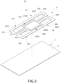
- Fig. 2 shows an exploded schematic view of the patch of the first embodiment of the present disclosure.
- a thermal signal transmission patch (hereinafter referred to as the patch 10) with an intelligent determination system of the present disclosure includes a substrate 1 and a loop layer 2.
- the loop layer 2 includes at least two loops in parallel to form two signal transmission loops.
- the two signal transmission loops are electrically connected to an external electrotherapy-and-hot-compress therapy apparatus (not shown in the figures) and a controller (not shown in the figures), as the signal transmission (thermal signal transmission) between the external electrotherapy-and-hot-compress therapy apparatus and the controller.
- the substrate 1 has no signal transmission function.
- the patch 10 further includes an adhesive layer 11 arranged on one side of the substrate 1, so that the substrate 1 adheres to the patient's skin surface.
- the substrate 1 is a sheet-shaped body, such as an adhesive bandage material which is the stretchable tape type, while the patch material of the adhesive bandage is a nonwoven cloth with good air permeability, stretchability and flexibility.
- the substrate 1 may be a non-adhesive bandage.
- the loop layer 2 is arranged on the one side of the substrate 1 with the adhesive layer 11.
- the loop layer 2 at least includes a first loop layer 21 and a second loop layer 22.
- the first loop layer 21 includes a first outer line segment 211 and a first inner line segment 212 which is electrically connected to the first outer line segment 211.
- the first outer line segment 211 is C-shaped. One end of the first outer line segment 211 is electrically connected to one end of the first inner line segment 212.
- the first inner line segment 212 includes two first straight-line segments 2121 and a first C-shaped line segment 2122 which is electrically connected between the two first straight-line segments 2121.
- the other end of the first outer line segment 211 fails to be directly connected to the other end of the first inner line segment 212; a first contact 21a is formed at the other end of the first outer line segment 211; a second contact 21b is formed at the other end of the first inner line segment 212.
- a third contact 21c is formed where the first outer line segment 211 and the first inner line segment 212 are electrically connected.
- the second loop layer 22 includes a second outer line segment 221 and a second inner line segment 222 which is electrically connected to the second outer line segment 221.
- the second outer line segment 221 is C-shaped. One end of the second outer line segment 221 is electrically connected to one end of the second inner line segment 222.
- the second inner line segment 222 includes two second straight-line segments 2221 and a second C-shaped line segment 2222 which is electrically connected between the two second straight-line segments 2221.
- the other end of the second outer line segment 221 fails to be directly connected to the other end of the second inner line segment 222; a fourth contact 22a is formed at the other end of the second outer line segment 221; a fifth contact 22b is formed at the other end of the second inner line segment 222.
- a sixth contact 22c is formed where the second outer line segment 221 and the second inner line segment 222 are electrically connected.
- the loop layer 2 mentioned above in the figures is a conductive cloth.
- the conductive cloth is a carrier with conductive function such as a silver fiber cloth, nanometer silver wires or a conductive paste (such as a thermal-transfer-type conductive gel) printing.
- the conductive cloth is processed and designed as a specific loop to achieve a single-piece single-layer which can perform thermotherapy treatment and which has the function of simple intelligent temperature control system, wherein the single-layer refers to a layer with a transmission function; other layers without electric signal transmission function may also be laminated on the other end of the main functional layer for modification, but do not affect the main functional layer.
- the intelligent temperature control refers to a temperature control system that has a determination function and can change due to changes in the external environment; for example, if the temperature of the product reaches 40 degrees, the system determines that the temperature is too high, and the product has other further operations to reduce harm.
- Fig. 3 shows a schematic block diagram of the circuit for electrically connecting the patch of the first embodiment, the external controller and the electrotherapy-and-hot-compress therapy apparatus of the present disclosure. As shown in Fig. 3 , when this embodiment is used, the first contact 21a and the second contact 21b of the first loop layer 21 of the loop layer 2, and the fourth contact 22a and the fifth contact 22b of the second loop layer 22 of the loop layer 2, are electrically connected to the external controller 20, which is an active component or a passive component.
- the active component is a proportional integral derivative (PID) controller; the proportional integral derivative controller is a microcontroller, a control chip or a temperature control chip.
- the passive component is an environmental sensor, such as a thermistor or a relay.
- the third contact 21c of the first loop layer 21 and the sixth contact 22c of the second loop layer 22 are electrically connected to an electrotherapy-and-hot-compress therapy apparatus 30.
- the first contact 21a is connected to the second contact 21b
- the fourth contact 22a is connected to the fifth contact 22b, so as to perform the electrotherapy
- a first loop-circuit of the first contact 21a and the second contact 21b is a first pole
- a second loop-circuit of the fourth contact 22a and the fifth contact 22b is a second pole
- the electric signal output voltage for electrotherapy is about 40V ⁇ 100V pulses
- the output current is 80mA.
- thermotherapy a parallel loop-circuit is required for circuit requirements; for example, the first contact 21a is connected to the fourth contact 22a, and the second contact 21b is connected to the fifth contact 22b, to form two loop-circuits in parallel;
- the electric signal output for thermotherapy is the constant voltage (commonly 5V/12V/24V, etc.), the constant current (0.7A/1.0A/1.5A, etc.), or changes in voltage and current according to the heating temperature design, so that the heating temperature can meet the requirement.
- the electrical connection of the first contact 21a, the second contact 21b, the fourth contact 22a and the fifth contact 22b of the loop layer 2 connected to the external controller 20 is changed (pins jumping/changing), so as to achieve a fast switching between the electrotherapy and the thermotherapy, allowing the user to feel both the electrotherapy and the thermotherapy simultaneously, or switching between the electrotherapy and the thermotherapy.
- the users are also allowed to adjust the operation mentioned above by themselves.
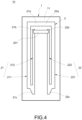
- Fig. 4 shows a schematic plan view of the patch of an embodiment not according to the claimed invention.
- this embodiment is substantially the same as the first embodiment, except that: the first loop layer 21 and the second loop layer 22 are connected to form a parallel loop-circuit; the first contact 21a of the first loop layer 21 is connected to the fourth contact 22a of the second loop layer 22 to form a first coil; the second contact 21b of the first loop layer 21 is connected to the fifth contact 22b of the second loop layer 22; the patch 10 further includes a first thermistor 201; the second contact 21b and the fifth contact 22b are electrically connected to the first thermistor 201 to form a second coil; the third contact 21c of the first loop layer 21 and the sixth contact 22c of the second loop layer 22 form an electrode connection part to be connected to the signal source (the electrotherapy-and-hot-compress therapy apparatus 30).
- the inner loop-circuit resistance is smaller, the outer loop-circuit resistance is larger, while there is the first thermistor 201 in the inner loop-circuit, wherein if the temperature is higher than 40 degrees, the first thermistor 201 is the open circuit; if the temperature is lower than 36 degrees, the thermistor 201 changes back to the short circuit. Because the temperature control range of the first thermistor 201 is not accurate enough and the first thermistor 201 is not sensitive enough, the dual-loop-circuit design is used to make the heating temperature of these two coils not too high and is used to avoid causing damage.
- the heating efficiency is 5W
- the inner loop-circuit resistance is 8.5 ohms
- the outer loop-circuit resistance is 12 ohms
- the total resistance including the cable connecting the signal source is about 5 ohms.
- the inner loop-circuit resistance is smaller, the line width is smaller, and the heating efficiency (the heat generated per unit area) is stronger, so the inner loop-circuit heats up fast, and the thermistor is triggered by the fast heating through the inner loop-circuit.
- the thermistor When the temperature reaches 40 degrees, the thermistor is cut off; at this time, only the outer loop-circuit continues to generate heat.
- the outer loop-circuit has a wider line width and a larger resistance; the overall heating efficiency is poor, and the temperature rise is slow, so that the overall system can maintain the temperature, and keep the temperature at 40 degrees (specific temperature).
- the patch 10 may be used in medical equipment, sport equipment or rehabilitation aids, such as compression stockings, compression garments, protectors and other highly elastic clothing combined with electrical stimulation (electrotherapy), thermotherapy, or elastic smart clothing (such as with input and output electric signal function or heating function), or thermotherapy products (such as heating eye masks, heating masks, heating blankets and heating clothing).
- medical equipment sport equipment or rehabilitation aids
- compression stockings compression garments, protectors and other highly elastic clothing combined with electrical stimulation (electrotherapy), thermotherapy, or elastic smart clothing (such as with input and output electric signal function or heating function), or thermotherapy products (such as heating eye masks, heating masks, heating blankets and heating clothing).
- Fig. 5 shows a schematic plan view of the patch of another embodiment not according to the claimed invention.
- this embodiment is substantially the same as the first embodiment or the second embodiment, except that: the patch 10 further includes a third loop layer 23, a first thermistor 201 and a second thermistor 202; the first loop layer 21, the second loop layer 22 and the third loop layer 23 are connected to form a parallel loop-circuit; the first contact 21a of the first loop layer 21 is connected to the fourth contact 22a of the second loop layer 22 to form the outermost layer coil; the second contact 21b of the first loop layer 21 is connected to the fifth contact 22b of the second loop layer 22; the second contact 21b and the fifth contact 22b are electrically connected to the first thermistor 201 to form the middle layer coil; the third loop layer 23 includes a first innermost line segment 231 and a second innermost line segment 232; the first innermost line segment 231 and the second innermost line segment 232 are two oppositely arranged arcuate shapes; a seventh contact 231a of the first innermost line segment 231 is formed at one end of the first inner
- the resistance value of the outermost layer coil connected as mentioned above is 25 ⁇ (ohms), which is set as a temperature-maintaining coil.
- the resistance value of the middle layer coil is 16.67 ⁇ (ohms), which is set as a slow heating coil; with the first thermistor 201, an open circuit is formed when the temperature exceeds 45 degrees.
- the resistance value of the innermost layer coil is 10 ⁇ (ohms), which is set as a fast-heating coil; with the second thermistor 202, an open circuit is formed when the temperature exceeds 45 degrees.
- the patch 10 of the present disclosure may be manufactured with the flexible printed circuit (FPC) board, which is a special kind of the printed circuit board and is also known as a flexible line-circuit board, a soft circuit board, a soft line-circuit board, a flexibility line-circuit board or a soft board, and so on, so that the patch 10 of the present disclosure has the industrial practicability.
- FPC flexible printed circuit
Landscapes
- Health & Medical Sciences (AREA)
- Life Sciences & Earth Sciences (AREA)
- Animal Behavior & Ethology (AREA)
- General Health & Medical Sciences (AREA)
- Public Health (AREA)
- Veterinary Medicine (AREA)
- Engineering & Computer Science (AREA)
- Biomedical Technology (AREA)
- Heart & Thoracic Surgery (AREA)
- Vascular Medicine (AREA)
- Nuclear Medicine, Radiotherapy & Molecular Imaging (AREA)
- Radiology & Medical Imaging (AREA)
- Physics & Mathematics (AREA)
- Thermal Sciences (AREA)
- Epidemiology (AREA)
- Pain & Pain Management (AREA)
- Physical Education & Sports Medicine (AREA)
- Rehabilitation Therapy (AREA)
- Thermotherapy And Cooling Therapy Devices (AREA)
- Measuring And Recording Apparatus For Diagnosis (AREA)
Claims (10)
- Wärmesignalübertragungs-Pflaster (10), wobei das Wärmesignalübertragungs-Pflaster (10) mit einer externen Steuerung (20), einem externen elektronischen Bauelement oder einer externen Signalquelle elektrisch verbindbar ist, wobei das Wärmesignalübertragungs-Pflaster (10) umfasst:ein Substrat (1), das ein blattförmiger Körper ist; undeine Leitungsschleifenschicht (2), die auf einer Seite des Substrats (1) angeordnet ist und mindestens eine erste Leitungsschleifenschicht (21) und eine zweite Leitungsschleifenschicht (22) umfasst,wobei die erste Leitungsschleifenschicht (21) einen ersten Kontakt (21a), einen zweiten Kontakt (21b), einen dritten Kontakt (21c), ein erstes äußeres Leitungssegment (211) und ein erstes inneres Leitungssegment (212), das elektrisch mit dem ersten äußeren Leitungssegment (211) verbunden ist, umfasstwobei die zweite Leitungsschleifenschicht (22) einen vierten Kontakt (22a), einen fünften Kontakt (22b), einen sechsten Kontakt (22c), ein zweites äußeres Leitungssegment (221) und ein zweites inneres Leitungssegment (222) umfasst, das elektrisch mit dem zweiten äußeren Leitungssegment (221) verbunden ist, wobei das erste äußere Leitungssegment (211) und das zweite äußere Leitungssegment (221) einen äußeren Leitungsschleifenstromkreis bilden und das erste innere Leitungssegment (212) und das zweite innere Leitungssegment (222) einen inneren Leitungsschleifenstromkreis bilden, wobei ein Widerstand des äußeren Leitungsschleifenstromkreises größer ist als ein Widerstand des inneren Leitungsschleifenstromkreises;wobei, wenn der dritte Kontakt (21c) und der sechste Kontakt (22c) elektrisch mit der externen Signalquelle verbunden sind, ein elektrischer Verbindungsmodus des ersten Kontakts (21a), des zweiten Kontakts (21b), des vierten Kontakts (22a) und des fünften Kontakts (22b) der Leitungsschleifenschicht (2), die elektrisch mit der externen Steuerung (20) oder der externen elektronischen Bauelement verbunden sind, geändert werden kann, um ein schnelles Umschalten zwischen einer Elektrotherapie und einer Thermotherapie zu erreichen;wobei der erste Kontakt (21a) mit dem zweiten Kontakt (21b) verbindbar ist und der vierte Kontakt (22a) mit dem fünften Kontakt (22b) verbindbar ist, so dass ein erster Leitungsschleifenstromkreis des ersten Kontakts (21a) und des zweiten Kontakts (21b) einen ersten Pol einen und ein zweiter Leitungsschleifenstromkreis des vierten Kontakts (22a) und des fünften Kontakts (22b) einen zweiten Pol bilden, um die Elektrotherapie durchzuführen;wobei der erste Kontakt (21a) mit dem vierten Kontakt (22a) verbindbar ist und der zweite Kontakt (21b) mit dem fünften Kontakt (22b) verbindbar ist, um zwei parallele Leitungsschleifenschaltungen zur Durchführung der Thermotherapie zu bilden.
- Wärmesignalübertragungs-Pflaster (10) nach Anspruch 1, wobei das erste äußere Leitungssegment (211) C-förmig ist; ein Ende des ersten äußeren Leitungssegments (211) elektrisch mit einem Ende des ersten inneren Leitungssegments (212) verbunden ist; das erste innere Leitungssegment (212) zwei erste gerade Leitungssegmente (2121) und ein erstes C-förmiges Leitungssegment (2122) umfasst, das elektrisch zwischen den beiden ersten geraden Leitungssegmenten (2121) verbunden ist; das andere Ende des ersten äußeren Leitungssegments (211) nicht unmittelbar mit dem anderen Ende des ersten inneren Leitungssegments (212) verbunden ist; der erste Kontakt (21a) an dem anderen Ende des ersten äußeren Leitungssegments (211) ausgebildet ist; der zweite Kontakt (21b) an dem anderen Ende des ersten inneren Leitungssegments (212) ausgebildet ist; der dritte Kontakt (21c) dort ausgebildet ist, wo das erste äußere Leitungssegment (211) und das erste innere Leitungssegment (212) elektrisch verbunden sind.
- Wärmesignalübertragungs-Pflaster (10) nach Anspruch 2, wobei das zweite äußere Leitungssegment (221) C-förmig ist; ein Ende des zweiten äußeren Leitungssegments (221) elektrisch mit einem Ende des zweiten inneren Leitungssegments (222) verbunden ist; das zweite innere Leitungssegment (222) zwei zweite gerade Leitungssegmente (2221) und ein zweites C-förmiges Leitungssegment (2222) umfasst, das elektrisch zwischen den beiden zweiten geraden Leitungssegmenten (2221) verbunden ist; das andere Ende des zweiten äußeren Leitungssegments (221) nicht unmittelbar mit dem anderen Ende des zweiten inneren Leitungssegments (222) verbunden ist; der vierte Kontakt (22a) an dem anderen Ende des zweiten äußeren Leitungssegments (221) ausgebildet ist; der fünfte Kontakt (22b) an dem anderen Ende des zweiten inneren Leitungssegments (222) ausgebildet ist; der sechste Kontakt (22c) dort ausgebildet ist, wo das zweite äußere Leitungssegment (221) und das zweite innere Leitungssegment (222) elektrisch miteinander verbunden sind.
- Wärmesignalübertragungs-Pflaster (10) nach Anspruch 1, wobei der erste Kontakt (21a) und der zweite Kontakt (21b) der ersten Leitungsschleifenschicht (21) und der vierte Kontakt (22a) und der fünfte Kontakt (22b) der zweiten Leitungsschleifenschicht (22) elektrisch mit der externen Steuerung (20) verbindbar sind.
- Wärmesignalübertragungs-Pflaster (10) nach Anspruch 1, wobei die externe Steuerung (20) ein Proportional-Integral-Differenzial-Regler ist.
- Wärmesignalübertragungs-Pflaster (10) nach Anspruch 1, wobei der dritte Kontakt (21c) der ersten Leitungsschleifenschicht (21) und der sechste Kontakt (22c) der zweiten Leitungsschleifenschicht (22) elektrisch mit einem Elektrotherapie- und Wärmekompressions-Therapiegerät (30) verbindbar sind.
- Wärmesignalübertragungs-Pflaster (10) nach Anspruch 1, das ferner eine Klebstoffschicht (11) umfasst, die auf der einen Seite des Substrats (1) angeordnet ist, wobei die Klebstoffschicht (11) und die Leitungsschleifenschicht (2) auf derselben einen Seite des Substrats (1) angeordnet sind.
- Wärmesignalübertragungs-Pflaster (10) nach Anspruch 7, wobei das Substrat (1) eine Klebebandage ist.
- Wärmesignalübertragungs-Pflaster (10) nach Anspruch 1, wobei die Leitungsschleifenschicht (2) ein leitfähiger Stoff ist.
- Wärmesignalübertragungs-Pflaster (10) nach Anspruch 1, wobei das Wärmesignalübertragungs-Pflaster (10) eine flexible Leiterplatte, eine flexible Leitungsplatine, eine weiche Leiterplatte, eine weiche Leitungsplatine, eine flexible Leitungsplatine oder eine weiche Platte ist.
Applications Claiming Priority (1)
| Application Number | Priority Date | Filing Date | Title |
|---|---|---|---|
| PCT/CN2020/111238 WO2022040957A1 (zh) | 2020-08-26 | 2020-08-26 | 具智能判断系统的热讯号传输的贴片 |
Publications (4)
| Publication Number | Publication Date |
|---|---|
| EP4205709A1 EP4205709A1 (de) | 2023-07-05 |
| EP4205709A4 EP4205709A4 (de) | 2023-11-08 |
| EP4205709B1 true EP4205709B1 (de) | 2024-06-19 |
| EP4205709C0 EP4205709C0 (de) | 2024-06-19 |
Family
ID=80352406
Family Applications (1)
| Application Number | Title | Priority Date | Filing Date |
|---|---|---|---|
| EP20950630.2A Active EP4205709B1 (de) | 2020-08-26 | 2020-08-26 | Patch mit intelligentem bestimmungssystem zur thermischen signalübertragung |
Country Status (3)
| Country | Link |
|---|---|
| US (1) | US20230233364A1 (de) |
| EP (1) | EP4205709B1 (de) |
| WO (1) | WO2022040957A1 (de) |
Family Cites Families (8)
| Publication number | Priority date | Publication date | Assignee | Title |
|---|---|---|---|---|
| US20160015962A1 (en) * | 2014-07-16 | 2016-01-21 | Mehdi Shokoueinejad Maragheh | Smart Patch For Wound Management |
| DE202015102429U1 (de) * | 2015-05-12 | 2015-05-28 | Well-Life Healthcare Limited | Heilapparat zur Thermo- und Elektrotherapie |
| CN205126846U (zh) * | 2015-11-25 | 2016-04-06 | 解渤 | 温灸理疗贴片及温灸理疗服装 |
| CN106994064A (zh) * | 2017-05-18 | 2017-08-01 | 韩恺 | 一种智能药贴 |
| CN107860483A (zh) * | 2017-12-26 | 2018-03-30 | 上海理好智能科技有限公司 | 一种带温度传感器的发热器及其制备方法 |
| CN109041294A (zh) * | 2018-08-16 | 2018-12-18 | 镇江市海格乐电子科技有限公司 | 一种电加热板 |
| TWM596618U (zh) | 2019-04-25 | 2020-06-11 | 鉭騏實業有限公司 | 第三醫學之電性親膚片及接電裝置 |
| CN210932172U (zh) * | 2019-05-23 | 2020-07-07 | 钽骐实业有限公司 | 电性亲肤片 |
-
2020
- 2020-08-26 US US17/923,222 patent/US20230233364A1/en active Pending
- 2020-08-26 EP EP20950630.2A patent/EP4205709B1/de active Active
- 2020-08-26 WO PCT/CN2020/111238 patent/WO2022040957A1/zh not_active Ceased
Also Published As
| Publication number | Publication date |
|---|---|
| US20230233364A1 (en) | 2023-07-27 |
| EP4205709A1 (de) | 2023-07-05 |
| WO2022040957A1 (zh) | 2022-03-03 |
| EP4205709A4 (de) | 2023-11-08 |
| EP4205709C0 (de) | 2024-06-19 |
Similar Documents
| Publication | Publication Date | Title |
|---|---|---|
| US20070049916A1 (en) | Tuned return electrode with matching inductor | |
| CN106456971B (zh) | 身体接触的便携式治疗仪 | |
| US20180280190A1 (en) | Tri-modal localized heating garment | |
| US20190029877A1 (en) | Tri-modal localized heating garment | |
| US20200404987A1 (en) | Tri-modal localized heating garment | |
| WO2013134477A1 (en) | Patient-warming apparatus including an electrosurgical return electrode | |
| JP2012024405A (ja) | 電気刺激治療用導子、および電気刺激治療装置 | |
| US20230363685A1 (en) | Wearable system for muscle activity sensing and feedback | |
| CN116832321A (zh) | 治疗仪 | |
| EP4205709A1 (de) | Patch mit intelligentem bestimmungssystem zur thermischen signalübertragung | |
| CN108836612A (zh) | 智能电加热暖宫仪及系统 | |
| TWI810478B (zh) | 具智慧判斷系統之熱訊號傳輸之貼片 | |
| CN211050710U (zh) | 一种电极加热贴片 | |
| CN210932172U (zh) | 电性亲肤片 | |
| CN102551948B (zh) | 一种加热防护织物和系统 | |
| US12397150B2 (en) | Functional protector with electric conduction and heat conduction | |
| CN212439706U (zh) | 治疗仪用多功能治疗垫 | |
| CN213466511U (zh) | 具有导电导热的功能性护具 | |
| CN211634902U (zh) | 加热式理疗电极片 | |
| CN202665969U (zh) | 一种腹背电针刺热疗保健器 | |
| CN213609388U (zh) | 一种体表药力渗透增强装置 | |
| CN217563800U (zh) | 一种发热片及其发热装置 | |
| CN213760226U (zh) | 多功能电连接的磁力贴片与控制器结构 | |
| CN223026538U (zh) | 一种复合型温控电极片 | |
| CN221751073U (zh) | 一种用于盆腔部位的自发热的导电电极 |
Legal Events
| Date | Code | Title | Description |
|---|---|---|---|
| STAA | Information on the status of an ep patent application or granted ep patent |
Free format text: STATUS: THE INTERNATIONAL PUBLICATION HAS BEEN MADE |
|
| PUAI | Public reference made under article 153(3) epc to a published international application that has entered the european phase |
Free format text: ORIGINAL CODE: 0009012 |
|
| STAA | Information on the status of an ep patent application or granted ep patent |
Free format text: STATUS: REQUEST FOR EXAMINATION WAS MADE |
|
| 17P | Request for examination filed |
Effective date: 20230224 |
|
| AK | Designated contracting states |
Kind code of ref document: A1 Designated state(s): AL AT BE BG CH CY CZ DE DK EE ES FI FR GB GR HR HU IE IS IT LI LT LU LV MC MK MT NL NO PL PT RO RS SE SI SK SM TR |
|
| A4 | Supplementary search report drawn up and despatched |
Effective date: 20231010 |
|
| RIC1 | Information provided on ipc code assigned before grant |
Ipc: A61N 1/36 20060101ALI20231004BHEP Ipc: A61N 1/32 20060101ALI20231004BHEP Ipc: A61N 1/28 20060101ALI20231004BHEP Ipc: A61N 1/08 20060101ALI20231004BHEP Ipc: A61N 1/04 20060101ALI20231004BHEP Ipc: A61H 39/00 20060101ALI20231004BHEP Ipc: A61F 7/00 20060101ALI20231004BHEP Ipc: A61F 7/02 20060101AFI20231004BHEP |
|
| DAV | Request for validation of the european patent (deleted) | ||
| DAX | Request for extension of the european patent (deleted) | ||
| GRAP | Despatch of communication of intention to grant a patent |
Free format text: ORIGINAL CODE: EPIDOSNIGR1 |
|
| STAA | Information on the status of an ep patent application or granted ep patent |
Free format text: STATUS: GRANT OF PATENT IS INTENDED |
|
| INTG | Intention to grant announced |
Effective date: 20240313 |
|
| GRAS | Grant fee paid |
Free format text: ORIGINAL CODE: EPIDOSNIGR3 |
|
| GRAA | (expected) grant |
Free format text: ORIGINAL CODE: 0009210 |
|
| STAA | Information on the status of an ep patent application or granted ep patent |
Free format text: STATUS: THE PATENT HAS BEEN GRANTED |
|
| AK | Designated contracting states |
Kind code of ref document: B1 Designated state(s): AL AT BE BG CH CY CZ DE DK EE ES FI FR GB GR HR HU IE IS IT LI LT LU LV MC MK MT NL NO PL PT RO RS SE SI SK SM TR |
|
| REG | Reference to a national code |
Ref country code: GB Ref legal event code: FG4D |
|
| REG | Reference to a national code |
Ref country code: CH Ref legal event code: EP |
|
| REG | Reference to a national code |
Ref country code: DE Ref legal event code: R096 Ref document number: 602020032823 Country of ref document: DE |
|
| U01 | Request for unitary effect filed |
Effective date: 20240701 |
|
| U07 | Unitary effect registered |
Designated state(s): AT BE BG DE DK EE FI FR IT LT LU LV MT NL PT SE SI Effective date: 20240710 |
|
| U20 | Renewal fee for the european patent with unitary effect paid |
Year of fee payment: 5 Effective date: 20240830 |
|
| PG25 | Lapsed in a contracting state [announced via postgrant information from national office to epo] |
Ref country code: HR Free format text: LAPSE BECAUSE OF FAILURE TO SUBMIT A TRANSLATION OF THE DESCRIPTION OR TO PAY THE FEE WITHIN THE PRESCRIBED TIME-LIMIT Effective date: 20240619 |
|
| PG25 | Lapsed in a contracting state [announced via postgrant information from national office to epo] |
Ref country code: GR Free format text: LAPSE BECAUSE OF FAILURE TO SUBMIT A TRANSLATION OF THE DESCRIPTION OR TO PAY THE FEE WITHIN THE PRESCRIBED TIME-LIMIT Effective date: 20240920 |
|
| PG25 | Lapsed in a contracting state [announced via postgrant information from national office to epo] |
Ref country code: NO Free format text: LAPSE BECAUSE OF FAILURE TO SUBMIT A TRANSLATION OF THE DESCRIPTION OR TO PAY THE FEE WITHIN THE PRESCRIBED TIME-LIMIT Effective date: 20240919 Ref country code: HR Free format text: LAPSE BECAUSE OF FAILURE TO SUBMIT A TRANSLATION OF THE DESCRIPTION OR TO PAY THE FEE WITHIN THE PRESCRIBED TIME-LIMIT Effective date: 20240619 Ref country code: GR Free format text: LAPSE BECAUSE OF FAILURE TO SUBMIT A TRANSLATION OF THE DESCRIPTION OR TO PAY THE FEE WITHIN THE PRESCRIBED TIME-LIMIT Effective date: 20240920 Ref country code: RS Free format text: LAPSE BECAUSE OF FAILURE TO SUBMIT A TRANSLATION OF THE DESCRIPTION OR TO PAY THE FEE WITHIN THE PRESCRIBED TIME-LIMIT Effective date: 20240919 |
|
| PG25 | Lapsed in a contracting state [announced via postgrant information from national office to epo] |
Ref country code: PL Free format text: LAPSE BECAUSE OF FAILURE TO SUBMIT A TRANSLATION OF THE DESCRIPTION OR TO PAY THE FEE WITHIN THE PRESCRIBED TIME-LIMIT Effective date: 20240619 |
|
| PG25 | Lapsed in a contracting state [announced via postgrant information from national office to epo] |
Ref country code: IS Free format text: LAPSE BECAUSE OF FAILURE TO SUBMIT A TRANSLATION OF THE DESCRIPTION OR TO PAY THE FEE WITHIN THE PRESCRIBED TIME-LIMIT Effective date: 20241019 |
|
| PG25 | Lapsed in a contracting state [announced via postgrant information from national office to epo] |
Ref country code: CZ Free format text: LAPSE BECAUSE OF FAILURE TO SUBMIT A TRANSLATION OF THE DESCRIPTION OR TO PAY THE FEE WITHIN THE PRESCRIBED TIME-LIMIT Effective date: 20240619 |
|
| PG25 | Lapsed in a contracting state [announced via postgrant information from national office to epo] |
Ref country code: RO Free format text: LAPSE BECAUSE OF FAILURE TO SUBMIT A TRANSLATION OF THE DESCRIPTION OR TO PAY THE FEE WITHIN THE PRESCRIBED TIME-LIMIT Effective date: 20240619 Ref country code: SK Free format text: LAPSE BECAUSE OF FAILURE TO SUBMIT A TRANSLATION OF THE DESCRIPTION OR TO PAY THE FEE WITHIN THE PRESCRIBED TIME-LIMIT Effective date: 20240619 |
|
| PG25 | Lapsed in a contracting state [announced via postgrant information from national office to epo] |
Ref country code: ES Free format text: LAPSE BECAUSE OF FAILURE TO SUBMIT A TRANSLATION OF THE DESCRIPTION OR TO PAY THE FEE WITHIN THE PRESCRIBED TIME-LIMIT Effective date: 20240619 Ref country code: SM Free format text: LAPSE BECAUSE OF FAILURE TO SUBMIT A TRANSLATION OF THE DESCRIPTION OR TO PAY THE FEE WITHIN THE PRESCRIBED TIME-LIMIT Effective date: 20240619 |
|
| PG25 | Lapsed in a contracting state [announced via postgrant information from national office to epo] |
Ref country code: SM Free format text: LAPSE BECAUSE OF FAILURE TO SUBMIT A TRANSLATION OF THE DESCRIPTION OR TO PAY THE FEE WITHIN THE PRESCRIBED TIME-LIMIT Effective date: 20240619 Ref country code: SK Free format text: LAPSE BECAUSE OF FAILURE TO SUBMIT A TRANSLATION OF THE DESCRIPTION OR TO PAY THE FEE WITHIN THE PRESCRIBED TIME-LIMIT Effective date: 20240619 Ref country code: RO Free format text: LAPSE BECAUSE OF FAILURE TO SUBMIT A TRANSLATION OF THE DESCRIPTION OR TO PAY THE FEE WITHIN THE PRESCRIBED TIME-LIMIT Effective date: 20240619 Ref country code: PL Free format text: LAPSE BECAUSE OF FAILURE TO SUBMIT A TRANSLATION OF THE DESCRIPTION OR TO PAY THE FEE WITHIN THE PRESCRIBED TIME-LIMIT Effective date: 20240619 Ref country code: IS Free format text: LAPSE BECAUSE OF FAILURE TO SUBMIT A TRANSLATION OF THE DESCRIPTION OR TO PAY THE FEE WITHIN THE PRESCRIBED TIME-LIMIT Effective date: 20241019 Ref country code: ES Free format text: LAPSE BECAUSE OF FAILURE TO SUBMIT A TRANSLATION OF THE DESCRIPTION OR TO PAY THE FEE WITHIN THE PRESCRIBED TIME-LIMIT Effective date: 20240619 Ref country code: CZ Free format text: LAPSE BECAUSE OF FAILURE TO SUBMIT A TRANSLATION OF THE DESCRIPTION OR TO PAY THE FEE WITHIN THE PRESCRIBED TIME-LIMIT Effective date: 20240619 |
|
| REG | Reference to a national code |
Ref country code: CH Ref legal event code: PL |
|
| PG25 | Lapsed in a contracting state [announced via postgrant information from national office to epo] |
Ref country code: MC Free format text: LAPSE BECAUSE OF FAILURE TO SUBMIT A TRANSLATION OF THE DESCRIPTION OR TO PAY THE FEE WITHIN THE PRESCRIBED TIME-LIMIT Effective date: 20240619 Ref country code: CH Free format text: LAPSE BECAUSE OF NON-PAYMENT OF DUE FEES Effective date: 20240831 |
|
| PLBE | No opposition filed within time limit |
Free format text: ORIGINAL CODE: 0009261 |
|
| STAA | Information on the status of an ep patent application or granted ep patent |
Free format text: STATUS: NO OPPOSITION FILED WITHIN TIME LIMIT |
|
| 26N | No opposition filed |
Effective date: 20250320 |
|
| GBPC | Gb: european patent ceased through non-payment of renewal fee |
Effective date: 20240919 |
|
| PG25 | Lapsed in a contracting state [announced via postgrant information from national office to epo] |
Ref country code: GB Free format text: LAPSE BECAUSE OF NON-PAYMENT OF DUE FEES Effective date: 20240919 |
|
| U20 | Renewal fee for the european patent with unitary effect paid |
Year of fee payment: 6 Effective date: 20250612 |
|
| PG25 | Lapsed in a contracting state [announced via postgrant information from national office to epo] |
Ref country code: IE Free format text: LAPSE BECAUSE OF NON-PAYMENT OF DUE FEES Effective date: 20240826 |
|
| PG25 | Lapsed in a contracting state [announced via postgrant information from national office to epo] |
Ref country code: CY Free format text: LAPSE BECAUSE OF FAILURE TO SUBMIT A TRANSLATION OF THE DESCRIPTION OR TO PAY THE FEE WITHIN THE PRESCRIBED TIME-LIMIT; INVALID AB INITIO Effective date: 20200826 |
|
| PG25 | Lapsed in a contracting state [announced via postgrant information from national office to epo] |
Ref country code: HU Free format text: LAPSE BECAUSE OF FAILURE TO SUBMIT A TRANSLATION OF THE DESCRIPTION OR TO PAY THE FEE WITHIN THE PRESCRIBED TIME-LIMIT; INVALID AB INITIO Effective date: 20200826 |