EP4205663A1 - Information processing device, information processing method, and program - Google Patents
Information processing device, information processing method, and program Download PDFInfo
- Publication number
- EP4205663A1 EP4205663A1 EP21875629.4A EP21875629A EP4205663A1 EP 4205663 A1 EP4205663 A1 EP 4205663A1 EP 21875629 A EP21875629 A EP 21875629A EP 4205663 A1 EP4205663 A1 EP 4205663A1
- Authority
- EP
- European Patent Office
- Prior art keywords
- catheter
- data
- image
- medical instrument
- region
- Prior art date
- Legal status (The legal status is an assumption and is not a legal conclusion. Google has not performed a legal analysis and makes no representation as to the accuracy of the status listed.)
- Pending
Links
- 230000010365 information processing Effects 0.000 title claims abstract description 83
- 238000003672 processing method Methods 0.000 title claims description 5
- 238000012545 processing Methods 0.000 claims description 187
- 230000015572 biosynthetic process Effects 0.000 claims description 152
- 238000003786 synthesis reaction Methods 0.000 claims description 152
- 238000012549 training Methods 0.000 description 123
- 238000013145 classification model Methods 0.000 description 36
- 230000006870 function Effects 0.000 description 33
- 238000000034 method Methods 0.000 description 29
- 238000012937 correction Methods 0.000 description 23
- 238000012986 modification Methods 0.000 description 20
- 230000004048 modification Effects 0.000 description 20
- 238000006243 chemical reaction Methods 0.000 description 16
- 230000014509 gene expression Effects 0.000 description 16
- 230000012447 hatching Effects 0.000 description 15
- 238000010801 machine learning Methods 0.000 description 15
- 238000002604 ultrasonography Methods 0.000 description 15
- 239000000523 sample Substances 0.000 description 14
- 238000010224 classification analysis Methods 0.000 description 12
- 230000001746 atrial effect Effects 0.000 description 11
- 230000015654 memory Effects 0.000 description 10
- 210000000056 organ Anatomy 0.000 description 10
- 230000000295 complement effect Effects 0.000 description 9
- 238000013527 convolutional neural network Methods 0.000 description 9
- 238000003745 diagnosis Methods 0.000 description 9
- 239000000284 extract Substances 0.000 description 8
- 238000010586 diagram Methods 0.000 description 7
- 238000002697 interventional radiology Methods 0.000 description 7
- 230000008569 process Effects 0.000 description 7
- 238000004891 communication Methods 0.000 description 6
- 210000005246 left atrium Anatomy 0.000 description 6
- 230000002194 synthesizing effect Effects 0.000 description 6
- 238000012360 testing method Methods 0.000 description 6
- 238000013528 artificial neural network Methods 0.000 description 5
- 238000000605 extraction Methods 0.000 description 5
- 210000005245 right atrium Anatomy 0.000 description 4
- 230000011218 segmentation Effects 0.000 description 4
- 230000008859 change Effects 0.000 description 3
- 238000001514 detection method Methods 0.000 description 3
- 238000011176 pooling Methods 0.000 description 3
- 210000000709 aorta Anatomy 0.000 description 2
- 230000017531 blood circulation Effects 0.000 description 2
- 210000004204 blood vessel Anatomy 0.000 description 2
- 238000002591 computed tomography Methods 0.000 description 2
- 210000004351 coronary vessel Anatomy 0.000 description 2
- 210000003743 erythrocyte Anatomy 0.000 description 2
- 230000007717 exclusion Effects 0.000 description 2
- 230000005484 gravity Effects 0.000 description 2
- 238000002608 intravascular ultrasound Methods 0.000 description 2
- 238000002372 labelling Methods 0.000 description 2
- 210000005240 left ventricle Anatomy 0.000 description 2
- 239000003550 marker Substances 0.000 description 2
- 238000012014 optical coherence tomography Methods 0.000 description 2
- 239000004065 semiconductor Substances 0.000 description 2
- 230000002861 ventricular Effects 0.000 description 2
- 238000012800 visualization Methods 0.000 description 2
- 244000208734 Pisonia aculeata Species 0.000 description 1
- 238000002679 ablation Methods 0.000 description 1
- 230000002159 abnormal effect Effects 0.000 description 1
- 238000002583 angiography Methods 0.000 description 1
- 210000002376 aorta thoracic Anatomy 0.000 description 1
- 210000000013 bile duct Anatomy 0.000 description 1
- 230000005540 biological transmission Effects 0.000 description 1
- 210000004369 blood Anatomy 0.000 description 1
- 239000008280 blood Substances 0.000 description 1
- 239000003086 colorant Substances 0.000 description 1
- 230000008878 coupling Effects 0.000 description 1
- 238000010168 coupling process Methods 0.000 description 1
- 238000005859 coupling reaction Methods 0.000 description 1
- 238000002592 echocardiography Methods 0.000 description 1
- 230000000694 effects Effects 0.000 description 1
- 238000002594 fluoroscopy Methods 0.000 description 1
- 238000010030 laminating Methods 0.000 description 1
- 230000003902 lesion Effects 0.000 description 1
- 210000003141 lower extremity Anatomy 0.000 description 1
- 238000002595 magnetic resonance imaging Methods 0.000 description 1
- 230000007257 malfunction Effects 0.000 description 1
- 230000000873 masking effect Effects 0.000 description 1
- 230000002107 myocardial effect Effects 0.000 description 1
- 210000004798 organs belonging to the digestive system Anatomy 0.000 description 1
- 210000000277 pancreatic duct Anatomy 0.000 description 1
- 238000002600 positron emission tomography Methods 0.000 description 1
- 210000001147 pulmonary artery Anatomy 0.000 description 1
- 210000003492 pulmonary vein Anatomy 0.000 description 1
- 230000000306 recurrent effect Effects 0.000 description 1
- 230000009467 reduction Effects 0.000 description 1
- 230000000241 respiratory effect Effects 0.000 description 1
- 210000005241 right ventricle Anatomy 0.000 description 1
- 230000006403 short-term memory Effects 0.000 description 1
- 230000003068 static effect Effects 0.000 description 1
Images


Classifications
-
- A—HUMAN NECESSITIES
- A61—MEDICAL OR VETERINARY SCIENCE; HYGIENE
- A61B—DIAGNOSIS; SURGERY; IDENTIFICATION
- A61B90/00—Instruments, implements or accessories specially adapted for surgery or diagnosis and not covered by any of the groups A61B1/00 - A61B50/00, e.g. for luxation treatment or for protecting wound edges
- A61B90/36—Image-producing devices or illumination devices not otherwise provided for
- A61B90/37—Surgical systems with images on a monitor during operation
-
- G—PHYSICS
- G06—COMPUTING; CALCULATING OR COUNTING
- G06T—IMAGE DATA PROCESSING OR GENERATION, IN GENERAL
- G06T7/00—Image analysis
- G06T7/0002—Inspection of images, e.g. flaw detection
- G06T7/0012—Biomedical image inspection
-
- A—HUMAN NECESSITIES
- A61—MEDICAL OR VETERINARY SCIENCE; HYGIENE
- A61B—DIAGNOSIS; SURGERY; IDENTIFICATION
- A61B5/00—Measuring for diagnostic purposes; Identification of persons
- A61B5/0059—Measuring for diagnostic purposes; Identification of persons using light, e.g. diagnosis by transillumination, diascopy, fluorescence
- A61B5/0062—Arrangements for scanning
- A61B5/0066—Optical coherence imaging
-
- A—HUMAN NECESSITIES
- A61—MEDICAL OR VETERINARY SCIENCE; HYGIENE
- A61B—DIAGNOSIS; SURGERY; IDENTIFICATION
- A61B5/00—Measuring for diagnostic purposes; Identification of persons
- A61B5/0059—Measuring for diagnostic purposes; Identification of persons using light, e.g. diagnosis by transillumination, diascopy, fluorescence
- A61B5/0082—Measuring for diagnostic purposes; Identification of persons using light, e.g. diagnosis by transillumination, diascopy, fluorescence adapted for particular medical purposes
- A61B5/0084—Measuring for diagnostic purposes; Identification of persons using light, e.g. diagnosis by transillumination, diascopy, fluorescence adapted for particular medical purposes for introduction into the body, e.g. by catheters
-
- A—HUMAN NECESSITIES
- A61—MEDICAL OR VETERINARY SCIENCE; HYGIENE
- A61B—DIAGNOSIS; SURGERY; IDENTIFICATION
- A61B8/00—Diagnosis using ultrasonic, sonic or infrasonic waves
- A61B8/08—Detecting organic movements or changes, e.g. tumours, cysts, swellings
- A61B8/0833—Detecting organic movements or changes, e.g. tumours, cysts, swellings involving detecting or locating foreign bodies or organic structures
- A61B8/0841—Detecting organic movements or changes, e.g. tumours, cysts, swellings involving detecting or locating foreign bodies or organic structures for locating instruments
-
- A—HUMAN NECESSITIES
- A61—MEDICAL OR VETERINARY SCIENCE; HYGIENE
- A61B—DIAGNOSIS; SURGERY; IDENTIFICATION
- A61B8/00—Diagnosis using ultrasonic, sonic or infrasonic waves
- A61B8/12—Diagnosis using ultrasonic, sonic or infrasonic waves in body cavities or body tracts, e.g. by using catheters
-
- A—HUMAN NECESSITIES
- A61—MEDICAL OR VETERINARY SCIENCE; HYGIENE
- A61B—DIAGNOSIS; SURGERY; IDENTIFICATION
- A61B8/00—Diagnosis using ultrasonic, sonic or infrasonic waves
- A61B8/52—Devices using data or image processing specially adapted for diagnosis using ultrasonic, sonic or infrasonic waves
- A61B8/5215—Devices using data or image processing specially adapted for diagnosis using ultrasonic, sonic or infrasonic waves involving processing of medical diagnostic data
-
- G—PHYSICS
- G06—COMPUTING; CALCULATING OR COUNTING
- G06V—IMAGE OR VIDEO RECOGNITION OR UNDERSTANDING
- G06V10/00—Arrangements for image or video recognition or understanding
- G06V10/20—Image preprocessing
- G06V10/25—Determination of region of interest [ROI] or a volume of interest [VOI]
-
- G—PHYSICS
- G06—COMPUTING; CALCULATING OR COUNTING
- G06V—IMAGE OR VIDEO RECOGNITION OR UNDERSTANDING
- G06V10/00—Arrangements for image or video recognition or understanding
- G06V10/70—Arrangements for image or video recognition or understanding using pattern recognition or machine learning
- G06V10/764—Arrangements for image or video recognition or understanding using pattern recognition or machine learning using classification, e.g. of video objects
-
- G—PHYSICS
- G16—INFORMATION AND COMMUNICATION TECHNOLOGY [ICT] SPECIALLY ADAPTED FOR SPECIFIC APPLICATION FIELDS
- G16H—HEALTHCARE INFORMATICS, i.e. INFORMATION AND COMMUNICATION TECHNOLOGY [ICT] SPECIALLY ADAPTED FOR THE HANDLING OR PROCESSING OF MEDICAL OR HEALTHCARE DATA
- G16H30/00—ICT specially adapted for the handling or processing of medical images
- G16H30/20—ICT specially adapted for the handling or processing of medical images for handling medical images, e.g. DICOM, HL7 or PACS
-
- A—HUMAN NECESSITIES
- A61—MEDICAL OR VETERINARY SCIENCE; HYGIENE
- A61B—DIAGNOSIS; SURGERY; IDENTIFICATION
- A61B17/00—Surgical instruments, devices or methods, e.g. tourniquets
- A61B17/00234—Surgical instruments, devices or methods, e.g. tourniquets for minimally invasive surgery
- A61B2017/00238—Type of minimally invasive operation
- A61B2017/00243—Type of minimally invasive operation cardiac
-
- A—HUMAN NECESSITIES
- A61—MEDICAL OR VETERINARY SCIENCE; HYGIENE
- A61B—DIAGNOSIS; SURGERY; IDENTIFICATION
- A61B90/00—Instruments, implements or accessories specially adapted for surgery or diagnosis and not covered by any of the groups A61B1/00 - A61B50/00, e.g. for luxation treatment or for protecting wound edges
- A61B90/36—Image-producing devices or illumination devices not otherwise provided for
- A61B2090/364—Correlation of different images or relation of image positions in respect to the body
- A61B2090/367—Correlation of different images or relation of image positions in respect to the body creating a 3D dataset from 2D images using position information
-
- A—HUMAN NECESSITIES
- A61—MEDICAL OR VETERINARY SCIENCE; HYGIENE
- A61B—DIAGNOSIS; SURGERY; IDENTIFICATION
- A61B90/00—Instruments, implements or accessories specially adapted for surgery or diagnosis and not covered by any of the groups A61B1/00 - A61B50/00, e.g. for luxation treatment or for protecting wound edges
- A61B90/36—Image-producing devices or illumination devices not otherwise provided for
- A61B90/37—Surgical systems with images on a monitor during operation
- A61B2090/373—Surgical systems with images on a monitor during operation using light, e.g. by using optical scanners
- A61B2090/3735—Optical coherence tomography [OCT]
-
- A—HUMAN NECESSITIES
- A61—MEDICAL OR VETERINARY SCIENCE; HYGIENE
- A61B—DIAGNOSIS; SURGERY; IDENTIFICATION
- A61B90/00—Instruments, implements or accessories specially adapted for surgery or diagnosis and not covered by any of the groups A61B1/00 - A61B50/00, e.g. for luxation treatment or for protecting wound edges
- A61B90/36—Image-producing devices or illumination devices not otherwise provided for
- A61B90/37—Surgical systems with images on a monitor during operation
- A61B2090/376—Surgical systems with images on a monitor during operation using X-rays, e.g. fluoroscopy
-
- A—HUMAN NECESSITIES
- A61—MEDICAL OR VETERINARY SCIENCE; HYGIENE
- A61B—DIAGNOSIS; SURGERY; IDENTIFICATION
- A61B90/00—Instruments, implements or accessories specially adapted for surgery or diagnosis and not covered by any of the groups A61B1/00 - A61B50/00, e.g. for luxation treatment or for protecting wound edges
- A61B90/36—Image-producing devices or illumination devices not otherwise provided for
- A61B90/37—Surgical systems with images on a monitor during operation
- A61B2090/378—Surgical systems with images on a monitor during operation using ultrasound
- A61B2090/3782—Surgical systems with images on a monitor during operation using ultrasound transmitter or receiver in catheter or minimal invasive instrument
-
- A—HUMAN NECESSITIES
- A61—MEDICAL OR VETERINARY SCIENCE; HYGIENE
- A61B—DIAGNOSIS; SURGERY; IDENTIFICATION
- A61B6/00—Apparatus or devices for radiation diagnosis; Apparatus or devices for radiation diagnosis combined with radiation therapy equipment
- A61B6/12—Arrangements for detecting or locating foreign bodies
-
- A—HUMAN NECESSITIES
- A61—MEDICAL OR VETERINARY SCIENCE; HYGIENE
- A61B—DIAGNOSIS; SURGERY; IDENTIFICATION
- A61B8/00—Diagnosis using ultrasonic, sonic or infrasonic waves
- A61B8/08—Detecting organic movements or changes, e.g. tumours, cysts, swellings
- A61B8/0883—Detecting organic movements or changes, e.g. tumours, cysts, swellings for diagnosis of the heart
-
- A—HUMAN NECESSITIES
- A61—MEDICAL OR VETERINARY SCIENCE; HYGIENE
- A61B—DIAGNOSIS; SURGERY; IDENTIFICATION
- A61B8/00—Diagnosis using ultrasonic, sonic or infrasonic waves
- A61B8/08—Detecting organic movements or changes, e.g. tumours, cysts, swellings
- A61B8/0891—Detecting organic movements or changes, e.g. tumours, cysts, swellings for diagnosis of blood vessels
-
- A—HUMAN NECESSITIES
- A61—MEDICAL OR VETERINARY SCIENCE; HYGIENE
- A61B—DIAGNOSIS; SURGERY; IDENTIFICATION
- A61B8/00—Diagnosis using ultrasonic, sonic or infrasonic waves
- A61B8/44—Constructional features of the ultrasonic, sonic or infrasonic diagnostic device
- A61B8/4444—Constructional features of the ultrasonic, sonic or infrasonic diagnostic device related to the probe
- A61B8/4461—Features of the scanning mechanism, e.g. for moving the transducer within the housing of the probe
-
- A—HUMAN NECESSITIES
- A61—MEDICAL OR VETERINARY SCIENCE; HYGIENE
- A61B—DIAGNOSIS; SURGERY; IDENTIFICATION
- A61B8/00—Diagnosis using ultrasonic, sonic or infrasonic waves
- A61B8/48—Diagnostic techniques
- A61B8/483—Diagnostic techniques involving the acquisition of a 3D volume of data
-
- G—PHYSICS
- G06—COMPUTING; CALCULATING OR COUNTING
- G06N—COMPUTING ARRANGEMENTS BASED ON SPECIFIC COMPUTATIONAL MODELS
- G06N3/00—Computing arrangements based on biological models
- G06N3/02—Neural networks
- G06N3/04—Architecture, e.g. interconnection topology
- G06N3/044—Recurrent networks, e.g. Hopfield networks
- G06N3/0442—Recurrent networks, e.g. Hopfield networks characterised by memory or gating, e.g. long short-term memory [LSTM] or gated recurrent units [GRU]
-
- G—PHYSICS
- G06—COMPUTING; CALCULATING OR COUNTING
- G06N—COMPUTING ARRANGEMENTS BASED ON SPECIFIC COMPUTATIONAL MODELS
- G06N3/00—Computing arrangements based on biological models
- G06N3/02—Neural networks
- G06N3/04—Architecture, e.g. interconnection topology
- G06N3/045—Combinations of networks
- G06N3/0455—Auto-encoder networks; Encoder-decoder networks
-
- G—PHYSICS
- G06—COMPUTING; CALCULATING OR COUNTING
- G06N—COMPUTING ARRANGEMENTS BASED ON SPECIFIC COMPUTATIONAL MODELS
- G06N3/00—Computing arrangements based on biological models
- G06N3/02—Neural networks
- G06N3/04—Architecture, e.g. interconnection topology
- G06N3/0464—Convolutional networks [CNN, ConvNet]
-
- G—PHYSICS
- G06—COMPUTING; CALCULATING OR COUNTING
- G06N—COMPUTING ARRANGEMENTS BASED ON SPECIFIC COMPUTATIONAL MODELS
- G06N3/00—Computing arrangements based on biological models
- G06N3/02—Neural networks
- G06N3/04—Architecture, e.g. interconnection topology
- G06N3/0475—Generative networks
-
- G—PHYSICS
- G06—COMPUTING; CALCULATING OR COUNTING
- G06N—COMPUTING ARRANGEMENTS BASED ON SPECIFIC COMPUTATIONAL MODELS
- G06N3/00—Computing arrangements based on biological models
- G06N3/02—Neural networks
- G06N3/08—Learning methods
- G06N3/09—Supervised learning
-
- G—PHYSICS
- G06—COMPUTING; CALCULATING OR COUNTING
- G06T—IMAGE DATA PROCESSING OR GENERATION, IN GENERAL
- G06T2207/00—Indexing scheme for image analysis or image enhancement
- G06T2207/30—Subject of image; Context of image processing
- G06T2207/30004—Biomedical image processing
- G06T2207/30021—Catheter; Guide wire
Definitions
- the present invention relates to an information processing device, an information processing method, and a program.
- Patent Literature 1 A catheter system that acquires an image by inserting an image acquisition catheter into a hollow organ such as a blood vessel is used (Patent Literature 1).
- Patent Literature 1 WO 2017/164071 A
- an object is to provide an information processing device and the like that assist in understanding of an image acquired by an image acquisition catheter.
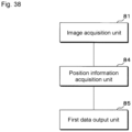
- An information processing device includes: an image acquisition unit that acquires a catheter image including an inner cavity obtained by an image acquisition catheter; a position information acquisition unit that acquires position information regarding a position of a medical instrument inserted into the inner cavity included in the catheter image; and a first data output unit that inputs the acquired catheter image and the acquired position information to a first trained model that, upon receiving input of the catheter image and the position information, outputs first data in which each region of the catheter image is classified into at least three of a biological tissue region, a medical instrument region where the medical instrument exists, and a non-biological tissue region, and outputs the first data.
- an information processing device and the like that assist in understanding of an image acquired by an image acquisition catheter.
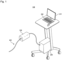
- Fig. 1 is an explanatory view explaining an outline of a catheter system 10.
- the catheter system 10 of the present embodiment is used for interventional radiology (IVR) that performs treatment of various organs while performing fluoroscopy using an image diagnosis device such as an X-ray fluoroscopic device.
- IVR interventional radiology
- an image diagnosis device such as an X-ray fluoroscopic device.
- the catheter system 10 includes an image acquisition catheter 40, a motor driving unit (MDU) 33, and an information processing device 20.
- the image acquisition catheter 40 is connected to the information processing device 20 via the MDU 33.
- a display device 31 and an input device 32 are connected to the information processing device 20.
- the input device 32 is an input device such as a keyboard, a mouse, a trackball, or a microphone.
- the display device 31 and the input device 32 may be integrally laminated to constitute a touchscreen.
- the input device 32 and the information processing device 20 may be integrally configured.
- Fig. 2 is an explanatory view explaining an outline of an image acquisition catheter 40.
- the image acquisition catheter 40 includes a probe portion 41 and a connector portion 45 disposed at an end part of the probe portion 41.
- the probe portion 41 is connected to the MDU 33 via the connector portion 45.
- a side far from the connector portion 45 of the image acquisition catheter 40 will be referred to as distal side.
- a shaft 43 is inserted into the probe portion 41.
- a sensor 42 is connected to the distal side of the shaft 43.
- a guide wire lumen 46 is provided at the distal end of the probe portion 41.
- the sensor 42 is, for example, an ultrasound transducer that transmits and receives ultrasound waves, or a transmission and reception unit for optical coherence tomography (OCT) that emits near-infrared light and receives reflected light.
- OCT optical coherence tomography
- a case where the image acquisition catheter 40 is an intravascular ultrasound (IVUS) catheter used when an ultrasound tomographic image is captured from the inside of a circulatory organ will be described as an example.
- IVUS intravascular ultrasound
- Fig. 3 is an explanatory view explaining the configuration of the catheter system 10.
- the catheter system 10 includes the information processing device 20, the MDU 33, and the image acquisition catheter 40.
- the information processing device 20 includes a control unit 21, a main storage device 22, an auxiliary storage device 23, a communication unit 24, a display unit 25, an input unit 26, a catheter control unit 271, and a bus.
- the control unit 21 is an arithmetic control device that executes the program of the present embodiment.
- the control unit 21 one or a plurality of central processing units (CPUs), graphics processing units (GPUs), tensor processing units (TPUs), multi-core CPUs, or the like are used.
- the control unit 21 is connected to each hardware unit constituting the information processing device 20 via the bus.
- the main storage device 22 is a storage device such as a static random access memory (SRAM), a dynamic random access memory (DRAM), or a flash memory.
- SRAM static random access memory
- DRAM dynamic random access memory
- flash memory a storage device such as a static random access memory (SRAM), a dynamic random access memory (DRAM), or a flash memory.
- the main storage device 22 temporarily saves necessary information in the middle of processing performed by the control unit 21 and a program being executed by the control unit 21.
- the auxiliary storage device 23 is a storage device such as an SR_AM, a flash memory, a hard disk, or a magnetic tape.
- the auxiliary storage device 23 saves a medical instrument trained model 611, a classification model 62, a program to be executed by the control unit 21, and various data necessary for executing the program.
- the communication unit 24 is an interface that performs communication between the information processing device 20 and a network.
- the display unit 25 is an interface that connects the display device 31 and the bus.
- the input unit 26 is an interface that connects the input device 32 and the bus.
- the catheter control unit 271 performs control of the MDU 33, control of the sensor 42, generation of an image based on a signal received from the sensor 42, and the like.
- the MDU 33 rotates the sensor 42 and the shaft 43 inside the probe portion 41.
- the catheter control unit 271 generates one catheter image 51 (see Fig. 4 ) for each rotation of the sensor 42.
- the generated catheter image 51 is a transverse tomographic image centered on the probe portion 41 and substantially perpendicular to the probe portion 41.
- the MDU 33 can further advance and retract the sensor 42 while rotating the sensor 42 and the shaft 43 inside the probe portion 41.
- the catheter control unit 271 continuously generates a plurality of catheter images 51 substantially perpendicular to the probe portion 41.
- the continuously generated catheter images 51 can be used to construct a three-dimensional image. Therefore, the image acquisition catheter 40 implements the function of a three-dimensional scanning catheter that sequentially acquires the plurality of catheter images 51 along the long direction.
- the advancing and retracting operation of the sensor 42 includes both an operation of advancing and retracting the entire probe portion 41 and an operation of advancing and retracting the sensor 42 inside the probe portion 41.
- the advancing and retracting operation may be automatically performed at a predetermined speed by the MDU 33 or may be manually performed by the user.
- the image acquisition catheter 40 is not limited to a mechanical scanning method of mechanically performing rotation and advancing and retracting.
- the image acquisition catheter 40 may be an electronic radial scanning type using the sensor 42 in which a plurality of ultrasound transducers are annularly arranged.
- the image acquisition catheter 40 it is possible to capture the catheter image 51 including a reflector present inside a circulatory organ such as red blood cells and an organ present outside the circulatory organ such as a respiratory organ and a digestive organ in addition to a biological tissue constituting the circulatory organ such as a heart wall and a blood vessel wall.
- a circulatory organ such as red blood cells
- an organ present outside the circulatory organ such as a respiratory organ and a digestive organ
- a biological tissue constituting the circulatory organ such as a heart wall and a blood vessel wall.
- the image acquisition catheter 40 is used for atrial septal puncture.
- a Brockenbrough needle is punctured into the fossa ovalis, which is a thin portion of the atrial septal, under ultrasound guide. The distal end of the Brockenbrough needle reaches the inside of the left atrium.
- the catheter image 51 visualizes the Brockenbrough needle in addition to a biological tissue constituting a circulatory organ such as the atrial septal, the right atrium, the left atrium, and the aorta, and a reflector such as red blood cells contained in blood flowing inside the circulatory organ.
- a user such as a medical doctor can safely perform atrial septal puncture by confirming the positional relationship between the fossa ovalis and the distal end of the Brockenbrough needle using the catheter image 51.
- the Brockenbrough needle is an example of the medical instrument of the present embodiment.
- the use of the catheter system 10 is not limited to the atrial septal puncture.
- the catheter system 10 can be used for manipulations such as transcatheter myocardial ablation, transcatheter valve replacement, and stent placement in a coronary artery or the like.
- the site of to be treated using the catheter system 10 is not limited to the periphery of the heart.
- the catheter system 10 can be used for treatment of various sites such as a pancreatic duct, a bile duct, and a lower extremity vessel.
- the control unit 21 may implement the function of the catheter control unit 271.
- the information processing device 20 is connected to various image diagnosis devices 37 such as an X-ray angiography device, an X-ray computed tomography (CT) device, a magnetic resonance imaging (MRI) device, a positron emission tomography (PET) device, or an ultrasound diagnosis device via a hospital information system (HIS) or the like.
- image diagnosis devices 37 such as an X-ray angiography device, an X-ray computed tomography (CT) device, a magnetic resonance imaging (MRI) device, a positron emission tomography (PET) device, or an ultrasound diagnosis device via a hospital information system (HIS) or the like.
- the information processing device 20 of the present embodiment is a dedicated ultrasound diagnosis device, or a personal computer, a tablet, a smartphone, or the like having the function of an ultrasound diagnosis device.
- a case where the information processing device 20 is also used for learning of a trained model such as the medical instrument trained model 611 and creation of training data will be described as an example.
- a computer, a server, or the like different from the information processing device 20 may be used for learning of the trained model and creation of the training data.
- control unit 21 performs software processing
- the processing described using the flowchart and the various trained models may be implemented by dedicated hardware.
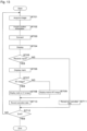
- Fig. 4 is an explanatory view explaining an outline of the operation of the catheter system 10.
- a case of capturing a plurality of catheter images 51 while pulling the sensor 42 at a predetermined speed and displaying an image in real time will be described as an example.
- the control unit 21 captures one catheter image 51 (step S501).
- the control unit 21 acquires position information of the medical instrument visualized in the catheter image 51 (step S502).
- the position of the medical instrument in the catheter image 51 is indicated by a cross mark ( ⁇ ).
- the control unit 21 records the catheter image 51, the position of the catheter image 51 in the long direction of the image acquisition catheter 40, and the position information of the medical instrument in association with one another in the auxiliary storage device 23 or a mass storage device connected to the HIS (step S503).
- the control unit 21 generates classification data 52 classified for each visualized subject for each portion constituting the catheter image 51 (step S504).
- the classification data 52 is illustrated by a schematic diagram in which the catheter image 51 is painted based on the classification result.
- the control unit 21 determines whether the user designates two-dimensional display or designates three-dimensional display (step S505). When determining that the user designates the two-dimensional display (2D in step S505), the control unit 21 displays the catheter image 51 and the classification data 52 on the display device 31 by two-dimensional display (step S506).
- step S505 in Fig. 4 description is made as if selection is either "two-dimensional display” and “three-dimensional display” such as “2D/3D". However, when the user selects "3D", the control unit 21 may display both "two-dimensional display” and "three-dimensional display”.
- step S511 When determining that the user designates three-dimensional display (3D in step S505), the control unit 21 determines whether or not the position information of the medical instrument sequentially recorded in step S503 is normal (step S511). When determining that the position information is not normal (NO in step S511), the control unit 21 corrects the position information (step S512). Details of the processing performed in steps S511 and S512 will be described later.
- control unit 21 When determining that the position information is normal (YES in step S511), or after the end of step S512, the control unit 21 performs three-dimensional display illustrating the structure of the site being observed and the position of the medical instrument (step S513). As described above, the control unit 21 may display both the three-dimensional display and the two-dimensional display on one screen.
- control unit 21 determines whether or not acquisition of the catheter image 51 has ended (step S507). For example, when receiving an end instruction from the user, the control unit 21 determines to end the processing.
- step S507 When determining not to end the processing (NO in step S507), the control unit 21 returns to step S501. When determining to end the processing (YES in step S507), the control unit 21 ends the processing.
- Fig. 4 explains the flow of processing in a case of performing the two-dimensional display (step S506) or the three-dimensional display (step S513) in real time during capturing of the series of catheter images 51.
- the control unit 21 may perform two-dimensional display or three-dimensional display in non-real time on the basis of the data recorded in step S503.
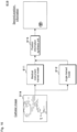
- Fig. 5A is an explanatory view schematically illustrating the operation of the image acquisition catheter 40.
- Fig. 5B is an explanatory view schematically illustrating the catheter image 51 captured by the image acquisition catheter 40.
- Fig. 5C is an explanatory view schematically explaining the classification data 52 generated on the basis of the catheter image 51.
- a radius-theta (RT) format and an XY format will be described with reference to Figs. 5A to 5C .
- the sensor 42 transmits and receives ultrasound waves while rotating inside the image acquisition catheter 40.
- the catheter control unit 271 acquires radial scanning line data around the image acquisition catheter 40.
- the catheter control unit 271 can generate the catheter image 51 illustrated in Fig. 5B in two formats of an RT format catheter image 518 and an XY format catheter image 519 on the basis of the scanning line data.
- the RT format catheter image 518 is an image generated by arranging pieces of scanning line data in parallel with one another.
- the lateral direction of the RT format catheter image 518 indicates the distance from the image acquisition catheter 40.
- the longitudinal direction of the RT format catheter image 518 indicates the scanning angle.
- One RT format catheter image 518 is formed by arraying, in parallel in the order of the scanning angle, the scanning line data acquired by the sensor 42 rotating by 360 degrees.
- the left side of the RT format catheter image 518 indicates a place close to the image acquisition catheter 40, and the right side of the RT format catheter image 518 indicates a place far from the image acquisition catheter 40.
- the XY format catheter image 519 is an image generated by radially arranging and interpolating the pieces of scanning line data.
- the XY format catheter image 519 indicates a tomographic image of the subject being cut perpendicularly to the image acquisition catheter 40 at the position of the sensor 42.
- Fig. 5C schematically illustrates the classification data 52 classified for each visualized subject for each portion constituting the catheter image 51.
- the classification data 52 can also be displayed in the two formats of RT format classification data 528 and XY format classification data 529. Since an image conversion method between the RT format and the XY format is known, description thereof is omitted.
- the thick right-downward hatching indicates a biological tissue region forming a cavity into which the image acquisition catheter 40 is inserted, such as an atrial wall and a ventricular wall.
- the thin left-downward hatching indicates the inside of the first cavity, which is a blood flow region into which the distal part of the image acquisition catheter 40 is inserted.
- the thin right-downward hatching indicates the inside of the second cavity, which is a blood flow region other than the first cavity.
- the first cavity is the right atrium
- the second cavity is the left atrium, the right ventricle, the left ventricle, the aorta, the coronary artery, and the like.
- first inner cavity region the inside of the first cavity
- second inner cavity region the inside of the second cavity
- the thick left-downward hatching indicates a non-inner cavity region, which is neither the first inner cavity region nor the second inner cavity region of the non-biological tissue region.
- the non-inner cavity region includes an out-of-cardiac region and a region outside the heart structure.
- the inside of the left atrium is also included in the non-inner cavity region.
- the inner cavity such as the left ventricle, the pulmonary artery, the pulmonary vein, and the aortic arch are also included in the non-inner cavity region when the distal wall cannot be sufficiently visualized.
- Black indicates a medical instrument region in which a medical instrument such as a Brockenbrough needle is visualized.
- the biological tissue region and the non-biological tissue region may be collectively referred to as biological tissue-related region.
- the medical instrument is not necessarily inserted into the same first cavity as the image acquisition catheter 40. Depending on the manipulation, the medical instrument may be inserted into the second cavity.
- the hatching and the black illustrated in Fig. 5C are examples of modes in which those regions can be distinguished. Those regions are displayed on the display device 31 using, for example, different colors.
- the control unit 21 implements the function of a first mode output unit that outputs the first inner cavity region, the second inner cavity region, and the biological tissue region in a distinguishable mode.
- the control unit 21 also implements the function of a second mode output unit that outputs the first inner cavity region, the second inner cavity region, the non-inner cavity region, and the biological tissue region in a distinguishable mode.
- the display in the XY format is suitable during the IVR manipulation.
- the information in the vicinity of the image acquisition catheter 40 is compressed and the data amount is reduced, and data that does not originally exist is added by interpolation at a position away from the image acquisition catheter 40. Therefore, when the catheter image 51 is analyzed, use of the RT format image can obtain a more accurate result than that by use of the XY format image.
- control unit 21 generates the RT format classification data 528 on the basis of the RT format catheter image 518.
- the control unit 21 converts the XY format catheter image 519 to generate the RT format catheter image 518, and converts the RT format classification data 528 to generate the XY format classification data 529.
- a “biological tissue region label” is recorded in a pixel classified into the “biological tissue region”
- a “first inner cavity region label” is recorded in a pixel classified into the “first inner cavity region”
- a “second inner cavity region label” is recorded in a pixel classified into the “second inner cavity region”
- a “non-inner cavity region label” is recorded in a pixel classified into the “non-inner cavity region”
- a “medical instrument region label” is recorded in a pixel classified into the “medical instrument region”
- a “non-biological tissue region label” is recorded in a pixel classified into the "non-biological tissue region”.
- Each label is indicated by an integer, for example.
- the control unit 21 may generate the XY format classification data 529 on the basis of the XY format catheter image 519.
- the control unit 21 may generate the RT format classification data 528 on the basis of the XY format classification data 529.
- Fig. 6 is an explanatory view explaining the configuration of a medical instrument trained model 611.
- the medical instrument trained model 611 is a model that receives the catheter image 51 and outputs the first position information regarding the position where the medical instrument is visualized.
- the medical instrument trained model 611 implements step S502 described with reference to Fig. 4 .
- An output layer of the medical instrument trained model 611 functions as a first position information output unit that outputs the first position information.
- input of the medical instrument trained model 611 is the RT format catheter image 518.
- the first position information is a probability that the medical instrument for each portion on the RT format catheter image 518 is visualized.
- a place where the probability that the medical instrument is visualized is high is indicated by dark hatching, and a place where the probability that the medical instrument is visualized is low is indicated by no hatching.
- the medical instrument trained model 611 is generated by machine learning using, for example, a neural network structure of a convolutional neural network (CNN).
- CNN convolutional neural network
- Examples of the CNN that can be used for generation of the medical instrument trained model 611 include a region based convolutional neural network (R-CNN), you only look once (YOLO), U-Net, and a generative adversarial network (GAN).
- R-CNN region based convolutional neural network
- YOLO you only look once
- U-Net a generative adversarial network
- the medical instrument trained model 611 may be generated using a neural network structure other than the CNN.
- the medical instrument trained model 611 may be a model that receives a plurality of catheter images 51 acquired in time series and outputs the first position information with respect to the latest catheter image 51.
- the medical instrument trained model 611 can be generated by combining a model that receives time-series input such as a recurrent neural network (RNN) with the above-described neural network structure.
- RNN recurrent neural network
- the RNN is, for example, a long short-term memory (LSTM).
- LSTM long short-term memory
- the medical instrument trained model 611 includes a memory portion that holds information regarding the catheter image 51 input in the past.
- the medical instrument trained model 611 outputs the first position information on the basis of the information held in the memory portion and the latest catheter image 51.
- the medical instrument trained model 611 may include a recursive input portion that inputs, together with the next catheter image 51, an output based on the catheter image 51 input in the past.
- the medical instrument trained model 611 outputs the first position information on the basis of the latest catheter image 51 and the input from the recursive input portion.
- the medical instrument trained model 611 may output a place where the probability that the medical instrument is visualized is high using the position of one pixel on the catheter image 51 that has received the input.
- the medical instrument trained model 611 may be a model that, after calculating the probability that the medical instrument is visualized for each site on the catheter image 51 as illustrated in Fig. 6 , outputs the position of the pixel having the highest probability.
- the medical instrument trained model 611 may output the position of the center of gravity of the region where the probability that the medical instrument is visualized exceeds a predetermined threshold.
- the medical instrument trained model 611 may output a region in which the probability that the medical instrument is visualized exceeds a predetermined threshold.
- the medical instrument trained model 611 is desirably a model that outputs the first position information of each of the plurality of medical instruments.
- the medical instrument trained model 611 may be a model that outputs only the first position information of one medical instrument.
- the control unit 21 can input, to the medical instrument trained model 611, the RT format catheter image 518 with masking on the periphery of the first position information output from the medical instrument trained model 611 and acquire the first position information of the second medical instrument. By repeating the same processing, the control unit 21 can also acquire the first position information of the third and subsequent medical instruments.
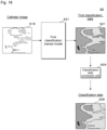
- Fig. 7 is an explanatory view explaining the configuration of a classification model 62.
- the classification model 62 is a model that receives the catheter image 51 and outputs the classification data 52 classified for each visualized subject for each portion constituting the catheter image 51.
- the classification model 62 implements step S504 described with reference to Fig. 4 .
- the classification model 62 classifies each pixel constituting the input RT format catheter image 518 into, for example, the "biological tissue region”, the “first inner cavity region”, the “second inner cavity region”, the “non-inner cavity region”, and the “medical instrument region”, and outputs the RT format classification data 528 in which the position of the pixel is associated with the label indicating the classification result.
- the classification model 62 may divide the catheter image 51 into regions of optional size, for example, a total of 9 pixels including 3 vertical pixels and 3 horizontal pixels, and output classification data 52 obtained by classifying those regions.
- the classification model 62 is, for example, a trained model that performs semantic segmentation on the catheter image 51. A specific example of the classification model 62 will be described later.
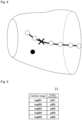
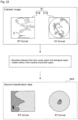
- Fig. 8 is an explanatory view explaining an outline of processing regarding position information.
- the plurality of catheter images 51 are captured while the sensor 42 is moved in the long direction of the image acquisition catheter 40.
- a substantially truncated cone line drawing schematically illustrates a biological tissue region three-dimensionally constructed on the basis of the plurality of catheter images 51.
- the inside of the substantially truncated cone means the first inner cavity region.
- White and black circles indicate the positions of the medical instruments acquired from the respective catheter images 51. Among them, since the black circle is at a position far away from the white circle, it is determined to be an erroneous detection. The shape of the medical instrument can be reproduced by the thick line smoothly coupling the white circles.
- a cross mark ( ⁇ ) indicates complement information obtained by complementing the position information of an undetected medical instrument.
- the medical instrument is reconstructed so as not to cause inconsistency using the position information of the medical instrument acquired from each of the plurality of catheter images 51.
- the catheter system 10 that accurately determines the position of the medical instrument and displays the shape of the medical instrument in the three-dimensional image.
- the catheter system 10 that assists understanding of the catheter image 51 acquired using the image acquisition catheter 40 by the display of steps S506 and S513.
- the user can accurately grasp the position of the medical instrument, and can safely perform IVR.
- the present embodiment relates to a generation method for the medical instrument trained model 611. Description of parts common to the first embodiment will be omitted. In the present embodiment, a case where the medical instrument trained model 611 is generated using the information processing device 20 described with reference to Fig. 3 will be described as an example.
- the medical instrument trained model 611 may be created using a computer or the like different from the information processing device 20.
- the medical instrument trained model 611 on which the machine learning is completed may be copied to the auxiliary storage device 23 via the network.
- the medical instrument trained model 611 trained by one piece of hardware can be used by the plurality of information processing devices 20.
- Fig. 9 is an explanatory view explaining a record layout of a medical instrument position training data database (DB) 71.
- the medical instrument position training data DB 71 is a database in which the catheter image 51 and the position information of the medical instrument are recorded in association with each other, and is used for training of the medical instrument trained model 611 by machine learning.
- the medical instrument position training data DB 71 has a catheter image field and a position information field.
- the catheter image field the catheter image 51 such as the RT format catheter image 518 is recorded.
- what is called sound ray data indicating an ultrasound signal received by the sensor 42 may be recorded.
- scanning line data generated on the basis of the sound ray data may be recorded.
- position information of the medical instrument visualized in the catheter image 51 is recorded.
- the position information is information indicating the position of one pixel marked on the catheter image 51 by a labeler as described later, for example.
- the position information may be information indicating a region of a circle centered around a point marked on the catheter image 51 by the labeler.
- the circle has a dimension that does not exceed the size of the medical instrument visualized in the catheter image 51.
- the circle has a size inscribed in a square having 50 vertical and horizontal pixels or less, for example.
- Fig. 10 is an example of a screen used for creation of the medical instrument position training data DB 71.
- a set of catheter images 51 of the RT format catheter image 518 and the XY format catheter image 519 are displayed on the screen of Fig. 10 .
- the RT format catheter image 518 and the XY format catheter image 519 are images created on the basis of the same sound ray data.
- a control button area 782 is displayed below the catheter image 51.
- a frame number of the catheter image 51 being displayed and a jump button used when the user inputs an optional frame number and jumps the display are arranged.
- buttons used when the user performs operations such as fast delivery, rewind, and frame advance are arranged below the frame number and the like. Since these buttons are similar to those generally used in various image reproduction devices and the like, the description thereof will be omitted.
- the user of the present embodiment is a person in charge of creating training data by viewing the catheter image 51 recorded in advance and labeling the position of the medical instrument.
- a person in charge of creating training data is referred to as labeler.
- the labeler is a medical doctor skilled in the interpretation of the catheter image 51, a laboratory technician, or a person trained to perform accurate labeling.
- marking there is a case where an operation of marking the catheter image 51 by the labeler to apply a label.
- the labeler observes the displayed catheter image 51 to determine the position where the medical instrument is visualized. In general, the region where the medical instrument is visualized is very small with respect to the area of the entire catheter image 51.
- the labeler moves a cursor 781 to substantially the center of the region where the medical instrument is visualized, and performs marking by a click operation or the like.
- the display device 31 is a touchscreen
- the labeler may perform marking by a tap operation using a finger, a stylus pen, or the like.
- the labeler may perform marking by what is called flick operation.
- the labeler may perform marking on the catheter image 51 of either of the RT format catheter image 518 and the XY format catheter image 519.
- the control unit 21 may display a mark at a corresponding position in the other catheter image 51.
- the control unit 21 creates a new record in the medical instrument position training data DB 71, and records the catheter image 51 and the position marked by the labeler in association with each other.
- the control unit 21 displays the next catheter image 51 on the display device 31.
- the labeler can sequentially perform marking on the plurality of catheter images 51 only by performing a click operation or the like on the catheter image 51 without operating each button in the control button area 782. All the operation performed by the labeler on one catheter image 51 in which one medical instrument is visualized is only one click operation or the like.
- the labeler can perform marking on each medical instrument by one click operation or the like.
- a case where one medical instrument is visualized in one catheter image 51 will be described as an example.
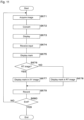
- Fig. 11 is a flowchart explaining the flow of the processing of a program for creating the medical instrument position training data DB 71.
- the program of Fig. 11 may be executed by hardware different from the information processing device 20.
- a large number of catheter images 51 are recorded in the auxiliary storage device 23 or an external mass storage device.
- the catheter image 51 is recorded in the auxiliary storage device 23 in the form of moving image data including a plurality of RT format catheter images 518 captured in time series will be described as an example.
- the control unit 21 acquires the RT format catheter image 518 of one frame from the auxiliary storage device 23 (step S671). By converting the RT format catheter image 518, the control unit 21 generates the XY format catheter image 519 (step S672). The control unit 21 displays, on the display device 31, the screen described with reference to Fig. 10 (step S673).
- the control unit 21 receives an input operation of the position information by the labeler via the input device 32 (step S674).
- the input operation is a click operation or a tap operation on the RT format catheter image 518 or the XY format catheter image 519.
- the control unit 21 displays a mark such as a small circle at a position where the input operation has been received (step S675).
- a mark such as a small circle at a position where the input operation has been received.
- the control unit 21 determines whether or not the image for which the input operation has been received in step S674 is the RT format catheter image 518 (step S676). When determining that the catheter image is the RT format catheter image 518 (YES in step S676), the control unit 21 displays a mark also at a corresponding position in the XY format catheter image 519 (step S677). When determining that the catheter image is not the RT format catheter image 518 (NO in step S676), the control unit 21 displays a mark also at a corresponding position in the RT format catheter image 518 (step S678).
- the control unit 21 creates a new record in the medical instrument position training data DB 71.
- the control unit 21 records the catheter image 51 and the position information input by the labeler in association with each other in the medical instrument position training data DB 71 (step S679).
- the catheter image 51 recorded in step S679 may be only the RT format catheter image 518 acquired in step S671 or both the RT format catheter image 518 and the XY format catheter image 519 generated in step S672.
- the catheter image 51 recorded in step S679 may be sound ray data for one rotation received by the sensor 42 or scanning line data generated by performing signal processing on the sound ray data.
- the position information recorded in step S679 is information indicating the position of one pixel on the RT format catheter image 518 corresponding to, for example, the position where the labeler has performed a click operation or the like using the input device 32.
- the position information may be information indicating a position where the labeler has performed a click operation or the like and a range around the position.
- the control unit 21 determines whether or not to end the processing (step S680). For example, when the processing of the catheter image 51 recorded in the auxiliary storage device 23 is ended, the control unit 21 determines to end the processing. When determining to end the processing (YES in step S680), the control unit 21 ends the processing.
- step S680 When determining not to end the processing (NO in step S680), the control unit 21 returns to step S671.
- step S671 the control unit 21 acquires the next RT format catheter image 518, and executes the processing in step S672 and subsequent steps. That is, the control unit 21 automatically acquires and displays the next RT format catheter image 518 without waiting for an operation on the button displayed in the control button area 782.
- control unit 21 records, in the medical instrument position training data DB 71, the training data based on the large number of RT format catheter images 518 recorded in the auxiliary storage device 23.
- the control unit 21 may display, for example, a "save button” on the screen described with reference to Fig. 10 , and execute step S679 when receiving selection of the "save button”. Furthermore, the control unit 21 may display, for example, an "AUTO button” on the screen described with reference to Fig. 10 , and may automatically execute step S679 without waiting for selection of the "save button” while receiving the selection of the "AUTO button”.
- the catheter image 51 recorded in the medical instrument position training data DB 71 in step S679 is the RT format catheter image 518
- the position information is the position of one pixel on the RT format catheter image 518
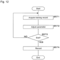
- Fig. 12 is a flowchart explaining the flow of the processing of a generation program of the medical instrument trained model 611.
- an untrained model in which, for example, a convolution layer, a pooling layer, and a fully connected layer are combined is prepared.
- the untrained model is, for example, a CNN model.
- Examples of the CNN that can be used for generation of the medical instrument trained model 611 include R-CNN, YOLO, U-Net, GAN, and the like.
- the medical instrument trained model 611 may be generated using a neural network structure other than the CNN.
- the control unit 21 acquires a training record used for training of one epoch from the medical instrument position training data DB 71 (step S571).
- the training record recorded in the medical instrument position training data DB 71 is a combination of the RT format catheter image 518 and the coordinates indicating the position of the medical instrument visualized in the RT format catheter image 518.
- the control unit 21 adjusts a parameter of the model so that the position of the pixel corresponding to the position information is output from the output layer (step S572).
- the program may appropriately have a function of causing the control unit 21 to execute reception of correction by the user, presentation of a basis of determination, additional learning, and the like.
- the control unit 21 determines whether or not to end the processing (step S573). For example, when ending the learning of the predetermined number of epochs, the control unit 21 determines to finish the processing.
- the control unit 21 may acquire test data from the medical instrument position training data DB 71, input the test data to the model under machine learning, and determine to end the processing in a case where an output with predetermined accuracy is obtained.
- step S573 When determining not to end the processing (NO in step S573), the control unit 21 returns to step S571.
- the control unit 21 records, in the auxiliary storage device 23, the parameter of the trained medical instrument position training data DB 71 (step S574). Thereafter, the control unit 21 ends the processing.
- the medical instrument trained model 611 that receives the catheter image 51 and outputs the first position information is generated.
- a model that receives time-series input such as RNN may be prepared.
- the RNN is, for example, an LSTM.
- the control unit 21 adjusts the parameter of the model so that the position of the pixel corresponding to the position information associated with the final RT format catheter image 518 is output in time series from the output layer.
- Fig. 13 is a flowchart explaining the flow of the processing of a program for adding data to the medical instrument position training data DB 71.
- the program of Fig. 13 is a program for adding training data to the medical instrument position training data DB 71 after creating the medical instrument trained model 611. The added training data is used for additional learning of the medical instrument trained model 611.
- a large number of catheter images 51 that have not yet been used for creation of the medical instrument position training data DB 71 are recorded in the auxiliary storage device 23 or the external mass storage device.
- the catheter image 51 is recorded in the auxiliary storage device 23 in the form of moving image data including a plurality of RT format catheter images 518 captured in time series will be described as an example.
- the control unit 21 acquires the RT format catheter image 518 of one frame from the auxiliary storage device 23 (step S701).
- the control unit 21 inputs the RT format catheter image 518 to the medical instrument trained model 611 and acquires the first position information (step S702) .
- the control unit 21 By converting the RT format catheter image 518, the control unit 21 generates the XY format catheter image 519 (step S703).
- the control unit 21 displays, on the display device 31, the screen described with reference to Fig. 10 in a state where the mark indicating the first position information acquired in step S702 is superimposed on each of the RT format catheter image 518 and the XY format catheter image 519 (step S704) .
- the labeler When determining that the position of the automatically displayed mark is inappropriate, the labeler performs one click operation or the like to input the correct position of the medical instrument. That is, the labeler inputs a correction instruction for the automatically displayed mark.
- the control unit 21 determines whether or not to have received an input operation by the labeler via the input device 32 within a predetermined time (step S705). It is desirable that the labeler can appropriately set the predetermined time.
- the input operation is a click operation or a tap operation on the RT format catheter image 518 or the XY format catheter image 519.
- the control unit 21 When determining to have received the input operation (YES in step S705), the control unit 21 displays a mark such as a small circle at the position where the input operation has been received (step S706).
- the mark displayed in step S706 desirably has a color, a shape, or the like different from those of the mark indicating the position information acquired in step S702.
- the control unit 21 may delete the mark indicating the position information acquired in step S702.
- the control unit 21 determines whether or not the image for which the input operation has been received in step S705 is the RT format catheter image 518 (step S707). When determining that the catheter image is the RT format catheter image 518 (YES in step S707)), the control unit 21 displays a mark also at a corresponding position in the XY format catheter image 519 (step S708). When determining that the catheter image is not the RT format catheter image 518 (NO in step S707), the control unit 21 displays a mark also at a corresponding position in the RT format catheter image 518 (step S709).
- the control unit 21 creates a new record in the medical instrument position training data DB 71.
- the control unit 21 records, in the medical instrument position training data DB 71, correction data in which the catheter image 51 is associated with the position information input by the labeler (step S710).
- control unit 21 When determining to have not received the input operation (NO in step S705), the control unit 21 creates a new record in the medical instrument position training data DB 71.
- the control unit 21 records, in the medical instrument position training data DB 71, non-correction data in which the catheter image 51 is associated with the first position information acquired in step S532 (step S711) .
- step S710 or step S711 ends, the control unit 21 determines whether or not to end the processing (step S712). For example, when the processing of the catheter image 51 recorded in the auxiliary storage device 23 is ended, the control unit 21 determines to end the processing. When determining to end the processing (YES in step S712), the control unit 21 ends the processing.
- step S712 When determining not to end the processing (NO in step S712), the control unit 21 returns to step S701. In step S701, the control unit 21 acquires the next RT format catheter image 518, and executes the processing in step S702 and subsequent steps. By the loop of steps S701 to S712, the control unit 21 adds, in the medical instrument position training data DB 71, the training data based on the large number of RT format catheter images 518 recorded in the auxiliary storage device 23.
- the control unit 21 may display an "OK button” for approving output by the medical instrument trained model 611, for example, on the screen described with reference to Fig. 10 .
- the control unit 21 determines that an instruction indicating "NO" is received in step S705 and executes step S711.
- the labeler can perform marking on one medical instrument visualized in the catheter image 51 only by one operation such as one click operation or one tap operation.
- the control unit 21 may receive an operation of marking one medical instrument by what is called a double click operation or a double tap operation. Since the marking work can be greatly saved as compared with the case of marking the boundary line of the medical instrument, the burden on the labeler can be reduced. According to the present embodiment, it is possible to create a large amount of training data in a short time.
- the labeler when a plurality of medical instruments are visualized on the catheter image 51, the labeler can perform marking on each medical instrument by one click operation or the like.
- the control unit 21 may display, for example, an "OK button” on the screen described with reference to Fig. 10 , and execute step S679 when receiving selection of the "OK button".
- the present embodiment by superimposing and displaying, on the catheter image 51, the position information acquired by the medical instrument trained model 611, it is possible to quickly create additional training data while reducing the burden on the labeler.
- the medical instrument position training data DB 71 may have a field for recording the type of medical instrument.
- the control unit 21 receives an input of the type of the medical instruments such as a "Brockenbrough needle", a "guide wire”, or a "balloon catheter".
- the medical instrument trained model 611 that outputs the type of the medical instrument in addition to the position of the medical instrument is generated.
- the present embodiment relates to the catheter system 10 that acquires second position information regarding the position of a medical instrument from the catheter image 51 using two trained models. Description of parts common to the second embodiment will be omitted.
- Fig. 14 is an explanatory view explaining visualization of a medical instrument.
- the medical instrument visualized in the RT format catheter image 518 and the XY format catheter image 519 is emphasized.
- acoustic shadow In Fig. 14 , a part of the acoustic shadow is indicated by vertical hatching.
- the acoustic shadow is visualized linearly in the horizontal direction.
- the acoustic shadow is visualized in a fan shape.
- a high luminance region is visualized in a site closer to the image acquisition catheter 40 than the acoustic shadow.
- the high luminance region may be visualized in a mode of what is called multiple echoes that regularly repeat along the scanning line direction.
- the scanning angle direction of the RT format catheter image 518 i.e., the lateral features in Fig. 14 .
- Fig. 15 is an explanatory view explaining the configuration of an angle trained model 612.
- the angle trained model 612 is a model that receives the catheter image 51 and outputs the scanning angle information regarding the scanning angle at which the medical instrument is visualized.
- Fig. 15 schematically illustrates the angle trained model 612 that receives the RT format catheter image 518 and outputs the scanning angle information indicating the probability that the medical instrument is visualized at each scanning angle, that is, in the longitudinal direction of the RT format catheter image 518. Since the medical instrument is visualized over a plurality of scanning angles, the total probability of outputting the scanning angle information exceeds 100%.
- the angle trained model 612 may extract and output an angle having a high probability that the medical instrument is visualized.
- the angle trained model 612 is generated by machine learning. By extracting the scanning angle of the position information from the position information field of the medical instrument position training data DB 71 described with reference to Fig. 9 , the scanning angle can be used for training data for generating the angle trained model 612.
- the control unit 21 acquires a training record used for training of one epoch from the medical instrument position training data DB 71 (step S571).
- the training record recorded in the medical instrument position training data DB 71 is a combination of the RT format catheter image 518 and the coordinates indicating the position of the medical instrument visualized in the RT format catheter image 518.
- the control unit 21 adjusts the parameter of the model so that the scanning angle corresponding to the position information is output from the output layer (step S572).
- the program may appropriately have a function of causing the control unit 21 to execute reception of correction by the user, presentation of a basis of determination, additional learning, and the like.
- the control unit 21 determines whether or not to end the processing (step S573). For example, when ending the learning of the predetermined number of epochs, the control unit 21 determines to finish the processing.
- the control unit 21 may acquire test data from the medical instrument position training data DB 71, input the test data to the model under machine learning, and determine to end the processing in a case where an output with predetermined accuracy is obtained.
- step S573 When determining not to end the processing (NO in step S573), the control unit 21 returns to step S571.
- the control unit 21 records, in the auxiliary storage device 23, the parameter of the trained medical instrument position training data DB 71 (step S574). Thereafter, the control unit 21 ends the processing.
- the angle trained model 612 that receives the catheter image 51 and outputs the information regarding the scanning angle is generated.
- a model that receives time-series input such as RNN may be prepared.
- the RNN is, for example, an LSTM.
- the control unit 21 adjusts the parameter of the model so that the information regarding the scanning angle associated with the final RT format catheter image 518 is output in time series from the output layer.
- control unit 21 may determine the scanning angle at which the medical instrument is visualized by pattern matching.
- Fig. 16 is an explanatory view explaining a position information model 619.
- the position information model 619 is a model that receives the RT format catheter image 518 and outputs the second position information indicating the position of the medical instrument being visualized.
- the position information model 619 includes the medical instrument trained model 611, the angle trained model 612, and a position information synthesis unit 615.
- the same RT format catheter image 518 is input to both the medical instrument trained model 611 and the angle trained model 612.
- the first position information is output from the medical instrument trained model 611.
- the first position information is a probability that the medical instrument is visualized at each site on the RT format catheter image 518.
- the probability that the medical instrument is visualized at the position where the distance from the center of the image acquisition catheter 40 is r and the scanning angle is ⁇ is indicated by P1 (r, ⁇ ).
- the scanning angle information is output from the angle trained model 612.
- the scanning angle information is a probability that the medical instrument is visualized at each scanning angle.
- the probability that the medical instrument is visualized in the direction of the scanning angle ⁇ is indicated by Pt ( ⁇ ).
- the position information synthesis unit 615 synthesizes the first position information and the scanning angle information to generate the second position information.
- the second position information is a probability that the medical instrument is visualized at each site on the RT format catheter image 518.
- the input end of the position information synthesis unit 615 functions as a first position information acquisition unit and functions as a scanning angle information acquisition unit.
- both the sum of P1 and the sum of Pt may be larger than 1.
- the second position information P2 (r, ⁇ ) at the position where the distance from the center of the image acquisition catheter 40 is r and the scanning angle is ⁇ is calculated by, for example, Expression (1-1).
- P 2 r ⁇ P 1 r ⁇ + kPt ⁇ k is a coefficient related to weighting between the first position information and the scanning angle information.
- the second position information P2 (r, ⁇ ) may be calculated by Expression (1-2).
- P 2 r ⁇ P 1 r ⁇ ⁇ Pt ⁇
- the second position information P2 (r, ⁇ ) may be calculated by Expression (1-3).
- Expression (1-3) is an expression for calculating an average value of the first position information and the scanning angle information.
- P 2 r ⁇ P 1 r ⁇ ⁇ Pt ⁇ / 2
- Each of the second position information P2 (r, ⁇ ) in Expressions (1-1) to (1-3) is not a probability but a numerical value relatively indicating the magnitude of the possibility that the medical instrument is visualized.
- the second position information may be information regarding a position where the value of P2 (r, ⁇ ) is the largest.
- the second position information may be determined by a function other than the expressions exemplified in Expressions (1-1) to (1-3).
- the second position information is an example of the position information of the medical instrument acquired in step S502 described with reference to Fig. 4 .
- the medical instrument trained model 611, the angle trained model 612, and the position information synthesis unit 615 cooperate to implement step S502 described with reference to Fig. 4 .
- the output end of the position information synthesis unit 615 functions as the second position information output unit that outputs the second position information on the basis of the first position information and the scanning angle information.
- Fig. 17 is a flowchart explaining a flow of the processing of the program of the third embodiment.
- the flowchart described with reference to Fig. 17 illustrates details of the processing in step S502 described with reference to Fig. 4 .
- the control unit 21 acquires one frame of the RT format catheter image 518 (step S541).
- the control unit 21 inputs the RT format catheter image 518 to the medical instrument trained model 611 and acquires the first position information (step S542).
- the control unit 21 inputs the RT format catheter image 518 to the angle trained model 612 and acquires the scanning angle information (step S543).
- the control unit 21 calculates the second position information on the basis of, for example, Expression (1-1) or Expression (1-2) (step S544). Thereafter, the control unit 21 ends the processing. Thereafter, the control unit 21 uses, as the position information in step S502, the second position information calculated in step S544.
- the catheter system 10 that accurately calculates the position information of the medical instrument visualized in the catheter image 51.
- the present embodiment relates to a specific example of the classification model 62 described with reference to Fig. 7 .
- Fig. 18 is an explanatory view explaining the configuration of the classification model 62.
- the classification model 62 includes a first classification trained model 621 and a classification data conversion unit 629.
- the first classification trained model 621 receives the RT format catheter image 518 and outputs first classification data 521 classified into the "biological tissue region", the "non-biological tissue region", and the “medical instrument region” for each portion constituting the RT format catheter image 518.
- the first classification trained model 621 further outputs the reliability of the classification result for each portion, that is, the probability that the classification result is correct.
- the output layer of the first classification trained model 621 functions as the first classification data output unit that outputs the first classification data 521.
- Fig. 18 schematically illustrates the first classification data 521 in the RT format.
- Thick right-downward hatching indicates biological tissue regions such as the atrial wall and the ventricular wall.
- Black indicates a medical instrument region in which a medical instrument such as a Brockenbrough needle is visualized.
- the lattice-like hatching indicates a non-biological tissue region that is neither a medical instrument region nor a biological tissue region.
- the first classification data 521 is converted into the classification data 52 by the classification data conversion unit 629.
- the lower right view of Fig. 18 schematically illustrates the RT format classification data 528.
- the non-biological tissue region is classified into three types, the first inner cavity region, the second inner cavity region, and the non-inner cavity region.
- the thin left-downward hatching indicates the first inner cavity region.
- the thin right-downward hatching indicates the second inner cavity region.
- the thick left-downward hatching indicates the non-inner cavity region.
- the classification data conversion unit 629 An outline of the processing performed by the classification data conversion unit 629 will be described.
- a region in contact with the image acquisition catheter 40 that is, the rightmost region in the first classification data 521 is classified as the first inner cavity region.
- a region surrounded by the biological tissue region is classified into the second inner cavity region.
- the classification of the second inner cavity region is desirably determined in a state where the upper end and the lower end of the RT format catheter image 518 are connected to form a cylindrical shape.
- a region that is neither the first inner cavity region nor the second inner cavity region of the non-biological tissue region is classified as the non-inner cavity region.
- Fig. 19 is an explanatory view explaining the first training data.
- the first training data is used when the first classification trained model 621 is generated by machine learning.
- the first training data may be created using a computer or the like different from the information processing device 20.
- the control unit 21 displays two types of the catheter images 51 of the RT format catheter image 518 and the XY format catheter image 519 on the display device 31.
- the labeler observes the displayed catheter image 51 and performs marking on four types of boundary line data of a "boundary line between the first inner cavity region and the biological tissue region", a "boundary line between the second inner cavity region and the biological tissue region", a "boundary line between the non-inner cavity region and the biological tissue region", and a "visible outline of the medical instrument region".
- the labeler may perform marking on the catheter image 51 of either of the RT format catheter image 518 and the XY format catheter image 519.
- the control unit 21 displays a boundary line corresponding to the marking at a corresponding position in the other catheter image 51.
- the labeler can check both the RT format catheter image 518 and the XY format catheter image 519 and perform appropriate marking.
- the labeler inputs which of the "biological tissue region”, the “non-biological tissue region”, and the “medical instrument region” each region divided by the four types of marked boundary line data is.
- the control unit 21 may automatically determine the region, and the labeler may issue a correction instruction as necessary.
- the first classification data 521 clearly indicating which of the "biological tissue region”, the “non-biological tissue region”, and the “medical instrument region” each region of the catheter image 51 is classified into is created.
- the first classification data 521 will be described with a specific example.
- a "biological tissue region label” is recorded in a pixel classified into the “biological tissue region”
- a "first inner cavity region label” is recorded in a pixel classified into the “first inner cavity region”
- a “second inner cavity region label” is recorded in a pixel classified into the “second inner cavity region”
- a "non-inner cavity region label” is recorded in a pixel classified into the "non-inner cavity region”
- a “medical instrument region label” is recorded in a pixel classified into the “medical instrument region”
- a "non-biological tissue region label” is recorded in a pixel classified into the "non-biological tissue region”.
- Each label is indicated by an integer, for example.
- the first classification data 521 is an example of label data in which position of a pixel is associated with a label.
- the control unit 21 records the catheter image 51 and the first classification data 521 in association with each other.
- a first training data DB is created by repeating the above processing and recording a large number of sets of data.
- the first training data DB in which the RT format catheter image 518 and the first classification data 521 in the RT format are recorded in association with each other in the first training data DB will be described as an example.
- the control unit 21 may generate the XY format classification data 529 on the basis of the XY format catheter image 519.
- the control unit 21 may generate the RT format classification data 528 on the basis of the XY format classification data 529.
- the U-Net structure includes a multi-layer encoder layer and a multi-layer decoder layer connected to the rear of the multi-layer encoder layer.
- Each encoder layer includes a pooling layer and a convolution layer.
- semantic segmentation a label is given to each pixel constituting an input image.
- the untrained model may be a Mask R-CNN model or a model that implements segmentation of another optional image.
- the control unit 21 acquires a training record used for training of one epoch from the first training data DB (step S571).
- the control unit 21 adjusts the parameter of the model so that the first classification data 521 in the RT format is output from the output layer (step S572).
- the program may appropriately have a function of causing the control unit 21 to execute reception of correction by the user, presentation of a basis of determination, additional learning, and the like.
- the control unit 21 determines whether or not to end the processing (step S573). For example, when ending the learning of the predetermined number of epochs, the control unit 21 determines to finish the processing.
- the control unit 21 may acquire test data from the first training data DB, input the test data to the model under machine learning, and determine to end the processing when an output with predetermined accuracy is obtained.
- step S573 When determining not to end the processing (NO in step S573), the control unit 21 returns to step S571.
- step S573 the control unit 21 records the parameter of the trained first classification trained model 621 in the auxiliary storage device 23 (step S574). Thereafter, the control unit 21 ends the processing.
- the first classification trained model 621 that receives the catheter image 51 and outputs the first classification data 521 is generated.
- a model that receives time-series input may be prepared.
- the model that receives the time-series input includes a memory portion that holds information regarding the RT format catheter image 518 input in the past, for example.
- the model that receives the time-series input may include a recursive input portion that inputs, together with the next RT format catheter image 518, an output to the RT format catheter image 518 input in the past.
- catheter images 51 acquired in time series makes it possible to implement the first classification trained model 621 that is hardly affected by image noise or the like and outputs the first classification data 521 with high accuracy.
- the first classification trained model 621 may be created using a computer or the like different from the information processing device 20.
- the first classification trained model 621 on which the machine learning is completed may be copied to the auxiliary storage device 23 via the network.
- the first classification trained model 621 trained by one piece of hardware can be used by the plurality of information processing devices 20.
- Fig. 20 is a flowchart explaining a flow of the processing of the program of the fourth embodiment.
- the flowchart described with reference to Fig. 20 illustrates details of the processing performed by the classification model 62 described with reference to Fig. 7 .
- the control unit 21 acquires one frame of the RT format catheter image 518 (step S551).
- the control unit 21 inputs the RT format catheter image 518 to the first classification trained model 621 and acquires the first classification data 521 (step S552).
- the control unit 21 extracts one continuous non-biological tissue region from the first classification data 521 (step S553).
- the processing on and after the extraction of the non-biological tissue region is desirably performed in a state where the upper end and the lower end of the RT format catheter image 518 are connected to form a cylindrical shape.
- the control unit 21 determines whether or not the non-biological tissue region extracted in step S552 is on a side in contact with the image acquisition catheter 40, that is, a part in contact with the left end of the RT format catheter image 518 (step S554). When determining that the non-biological tissue region is on the side in contact with the image acquisition catheter 40 (YES in step S554), the control unit 21 determines that the non-biological tissue region extracted in step S553 is the first inner cavity region (step S555).
- the control unit 21 determines whether or not the non-biological tissue region extracted in step S552 is surrounded by the biological tissue region (step S556).
- the control unit 21 determines that the non-biological tissue region extracted in step S553 is the second inner cavity region (step S557).
- steps S555 and S557 the control unit 21 implements the function of an inner cavity region extraction unit.
- control unit 21 determines that the non-biological tissue region extracted in step S553 is the non-inner cavity region (step S558).
- step S557 the control unit 21 determines whether or not to have ended the processing of all non-biological tissue regions (step S559). When determining not to have ended the processing (NO in step S559), the control unit 21 returns to step S553. When determining that the processing has ended (YES in step S559), the control unit 21 ends the processing.
- the control unit 21 implements the function of the classification data conversion unit 629 by the processing from step S553 to step S559.
- the first classification trained model 621 may be a model that classifies the XY format catheter image 519 into a biological tissue region, a non-biological tissue region, and a medical instrument region.
- the first classification trained model 621 may be a model that classifies the RT format catheter image 518 into the biological tissue region and the non-biological tissue region. In such a case, the labeler needs not perform marking on the medical instrument region.
- the present embodiment it is possible to generate the first classification trained model 621 that classifies the catheter image 51 into the biological tissue region, the non-biological tissue region, and the medical instrument region. According to the present embodiment, it is possible to provide the catheter system 10 that generates the classification data 52 using the generated first classification trained model 621.
- the labeler may input which of the "biological tissue region”, the “first inner cavity region”, the “second inner cavity region”, the “non-inner cavity region”, and the “medical instrument region” each region divided by the four types of boundary line data having been marked.
- the classification model 62 that classifies the catheter image 51 into the "biological tissue region", the "first inner cavity region”, the “second inner cavity region”, the “non-inner cavity region”, and the “medical instrument region” without using the classification data conversion unit 629.
- the present embodiment relates to the catheter system 10 using a synthesis classification model 626 that synthesizes the classification data 52 output from each of the two classification trained models. Description of parts common to the fourth embodiment will be omitted.
- Fig. 21 is an explanatory view explaining the configuration of the classification model 62 of the fifth embodiment.
- the classification model 62 includes the synthesis classification model 626 and the classification data conversion unit 629.
- the synthesis classification model 626 includes the first classification trained model 621, a second classification trained model 622, and a classification data synthesis unit 628. Since the first classification trained model 621 is similar to that of the fourth embodiment, the description thereof will be omitted.
- the second classification trained model 622 is a model that receives the RT format catheter image 518 and outputs the second classification data 522 classified into the "biological tissue region", the "non-biological tissue region", and the “medical instrument region” for each portion constituting the RT format catheter image 518.
- the second classification trained model 622 further outputs the reliability of the classification result for each portion, that is, the probability that the classification result is correct. Details of the second classification trained model 622 will be described later.
- the classification data synthesis unit 628 synthesizes the first classification data 521 and the second classification data 522 to generate synthesis classification data 526. That is, the input end of the classification data synthesis unit 628 implements the functions of a first classification data acquisition unit and a second classification data acquisition unit. The output end of the classification data synthesis unit 628 implements the function of a synthesis classification data output unit.
- the synthesis classification data 526 is converted into classification data 52 by the classification data conversion unit 629. Since the processing performed by the classification data conversion unit 629 is similar to that of the fourth embodiment, the description thereof will be omitted.
- Fig. 22 is an explanatory view explaining the second training data.
- the second training data is used when the second classification trained model 622 is generated by machine learning.
- a case where the second training data is created using the information processing device 20 described with reference to Fig. 3 will be described as an example.
- the second training data may be created using a computer or the like different from the information processing device 20.
- the control unit 21 displays two types of the catheter images 51 of the RT format catheter image 518 and the XY format catheter image 519 on the display device 31.
- the labeler observes the displayed catheter image 51 and performs marking on two types of boundary line data of the "boundary line between the first inner cavity region and the biological tissue region" and the "visible outline of the medical instrument region".
- the labeler may perform marking on the catheter image 51 of either of the RT format catheter image 518 and the XY format catheter image 519.
- the control unit 21 displays a boundary line corresponding to the marking at a corresponding position in the other catheter image 51.
- the labeler can check both the RT format catheter image 518 and the XY format catheter image 519 and perform appropriate marking.
- the labeler inputs which of the "biological tissue region”, the “non-biological tissue region”, and the “medical instrument region” each region divided by the two types of marked boundary line data is.
- the control unit 21 may automatically determine the region, and the labeler may issue a correction instruction as necessary.
- the second classification data 522 clearly indicating which region of the "biological tissue region”, the “non-biological tissue region”, and the “medical instrument region” each portion of the catheter image 51 is classified into is created.
- the second classification data 522 will be described with a specific example.
- a "biological tissue region label” is recorded in a pixel classified into the "biological tissue region”
- a "non-biological tissue region label” is recorded in a pixel classified into the “non-biological tissue region”
- a "medical instrument region label” is recorded in a pixel classified into the "medical instrument region”.
- Each label is indicated by an integer, for example.
- the second classification data 522 is an example of label data in which position of a pixel is associated with a label.
- the control unit 21 records the catheter image 51 and the second classification data 522 in association with each other.
- a second training data DB is created by repeating the above processing and recording a large number of sets of data.
- the second classification trained model 622 can be generated by performing processing similar to the machine learning described in the fourth embodiment using the second training data DB.
- the second classification trained model 622 may be a model that classifies the XY format catheter image 519 into the biological tissue region, the non-biological tissue region, and the medical instrument region.
- the second classification trained model 622 may be a model that classifies the RT format catheter image 518 into the biological tissue region and the non-biological tissue region. In such a case, the labeler needs not perform marking on the medical instrument region.
- Creation of the second classification data 522 can be performed in a shorter time than creation of the first classification data 521.
- the labeler training for creating the second classification data 522 can be performed in a shorter time than the labeler training for creating the first classification data 521.
- a larger amount of training data can be registered in the second training data DB than in the first training DB.
- the second classification trained model 622 that can identify the boundary between the first inner cavity region and the biological tissue region and the outer shape of the medical instrument region with higher accuracy than the first classification trained model 621 can be generated. However, since the second classification trained model 622 does not train a non-biological tissue region other than the first inner cavity region, it is not possible to identify the non-biological tissue region from the biological tissue region.
- the processing performed by the classification data synthesis unit 628 will be described.
- the same RT format catheter image 518 is input to both the first classification trained model 621 and the second classification trained model 622.
- the first classification data 521 is output from the medical instrument trained model 611.
- the second classification data 522 is output from the second classification trained model 622.
- the first classification trained model 621 and the second classification trained model 622 may output a label and a probability classified for each range of a total of 9 pixels including 3 vertical pixels and 3 horizontal pixels of the RT format catheter image 518, for example,.
- the reliability that the first classification trained model 621 is a biological tissue region is indicated by Q1t (r, ⁇ ).
- Q1t (r, ⁇ ) 0.
- the reliability that the second classification trained model 622 is a biological tissue region is indicated by Q2t (r, ⁇ ).
- Q2t (r, ⁇ ) 0.
- the classification data synthesis unit 628 calculates a synthesis value Qt (r, ⁇ ) on the basis of, for example, Expression (5-1).
- Qt (r, ⁇ ) is not a correct probability of the classification into the biological tissue region, but is a numerical value relatively indicating the magnitude of the reliability of being the biological tissue region.
- Qt r , ⁇ Q 1 t r , ⁇ ⁇ Q 2 t r , ⁇
- the classification data synthesis unit 628 classifies a pixel having Qt (r, ⁇ ) of 0.5 or more into the biological tissue region.
- the reliability that the first classification trained model 621 is the medical instrument region is indicated by Q1c (r, ⁇ )
- the reliability that the second classification trained model 622 is the medical instrument region is indicated by Q2c (r, ⁇ ).
- the classification data synthesis unit 628 calculates a synthesis value Qc (r, ⁇ ) on the basis of, for example, Expression (5-2).
- Qc (r, ⁇ ) is not a correct probability of the classification into the medical instrument region, but is a numerical value relatively indicating the magnitude of the reliability of being the medical instrument region.
- Qc r , ⁇ Q 1 c r , ⁇ ⁇ Q 2 c r , ⁇
- the classification data synthesis unit 628 classifies a pixel having Qc (r, ⁇ ) of 0.5 or more into the medical instrument region.
- the classification data synthesis unit 628 classifies a pixel that has been classified into neither the medical instrument region nor the biological tissue region into the non-biological tissue region.
- the classification data synthesis unit 628 generates the synthesis classification data 526 in which the first classification data 521 and the second classification data 522 are synthesized.
- the synthesis classification data 526 is converted into the RT format classification data 528 by the classification data conversion unit 629.
- Expressions (5-1) and (5-2) are examples.
- the threshold when the classification data synthesis unit 628 performs classification is also an example.
- the classification data synthesis unit 628 may be a trained model that receives the first classification data 521 and the second classification data 522 and outputs the synthesis classification data 526.
- the first classification data 521 may be input to the classification data synthesis unit 628 after being classified into the "biological tissue region", the "first inner cavity region”, the “second inner cavity region”, the “non-inner cavity region”, and the “medical instrument region” by the classification data conversion unit 629 described in the fourth embodiment.
- the first classification trained model 621 may be a model that classifies the catheter image 51 described in the modification 4-1 into the "biological tissue region", the "first inner cavity region”, the “second inner cavity region”, the “non-inner cavity region”, and the "medical instrument region”.
- the classification data synthesis unit 628 can output the synthesis classification data 526 classified into the "biological tissue region", the "first inner cavity region”, the “second inner cavity region”, the “non-inner cavity region”, and the "medical instrument region". In such a case, it is not necessary to input the synthesis classification data 526 to the classification data conversion unit 629 to convert the synthesis classification data into the RT format classification data 528.
- Fig. 23 is a flowchart explaining a flow of the processing of the program of the fifth embodiment.
- the flowchart described with reference to Fig. 23 illustrates details of the processing performed by the classification model 62 described with reference to Fig. 7 .
- the control unit 21 acquires one frame of the RT format catheter image 518 (step S581). By step S581, the control unit 21 implements the function of the image acquisition unit.
- the control unit 21 inputs the RT format catheter image 518 to the first classification trained model 621 and acquires the first classification data 521 (step S582).
- the control unit 21 inputs the RT format catheter image 518 to the second classification trained model 622 and acquires the second classification data 522 (step S583).
- the control unit 21 starts a classification synthesis subroutine (step S584).
- the classification synthesis subroutine is a subroutine that synthesizes first classification data 521 and second classification data 522 to generate the synthesis classification data 526. The flow of processing of the classification synthesis subroutine will be described later.
- the control unit 21 extracts one continuous non-biological tissue region from the synthesis classification data 526 (step S585).
- the processing on and after the extraction of the non-biological tissue region is desirably performed in a state where the upper end and the lower end of the RT format catheter image 518 are connected to form a cylindrical shape.
- the control unit 21 determines whether or not the non-biological tissue region extracted in step S585 is on a side in contact with the image acquisition catheter 40 (step S554).
- the processing up to step S559 is the same as the processing flow of the program of the fourth embodiment described with reference to Fig. 20 , and thus the description thereof is omitted.
- the control unit 21 determines whether or not to have ended the processing of all non-biological tissue regions (step S559). When determining not to have ended the processing (NO in step S559), the control unit 21 returns to step S585. When determining that the processing has ended (YES in step S559), the control unit 21 ends the processing.
- Fig. 24 is a flowchart explaining a flow of the processing of a subroutine of classification synthesis.
- the classification synthesis subroutine is a subroutine that synthesizes first classification data 521 and second classification data 522 to generate the synthesis classification data 526.
- the control unit 21 selects a pixel to be processed (step S601).
- the control unit 21 acquires a reliability Q1t (r, ⁇ ) that the pixel being processed is in the biological tissue region from the first classification data 521 (step S602).
- the control unit 21 acquires a reliability Q2t (r, ⁇ ) that the pixel being processed is in the biological tissue region from the second classification data 522 (step S603).
- the control unit 21 calculates the synthesis value Qt (r, ⁇ ) on the basis of, for example, Expression (5-1) (step S604).
- the control unit 21 determines whether or not the synthesis value Qt (r, ⁇ ) is equal to or greater than a predetermined threshold (step S605).
- the predetermined threshold is, for example, 0.5.
- the control unit 21 classifies the pixel being processed into the "biological tissue region" (step S606).
- the control unit 21 acquires a reliability Q1c (r, ⁇ ) that the pixel being processed is in the medical instrument region from the first classification data 521 (step S611).
- the control unit 21 acquires a reliability Q2c (r, ⁇ ) that the pixel being processed is in the medical instrument region from the second classification data 522 (step S612).
- the control unit 21 calculates the synthesis value Qc (r, ⁇ ) on the basis of, for example, Expression (5-2) (step S613).
- the control unit 21 determines whether or not the synthesis value Qc (r, ⁇ ) is equal to or greater than a predetermined threshold (step S614).
- the predetermined threshold is, for example, 0.5.
- control unit 21 When determining that the synthesis value is equal to or greater than the predetermined threshold (YES in step S614), the control unit 21 classifies the pixel being processed into the "medical instrument region" (step S615). When determining that the synthesis value is less than the predetermined threshold (NO in step S614), the control unit 21 classifies the pixel being processed into the "non-biological tissue region" (step S616).
- step S615, or step S616, the control unit 21 determines whether or not to have ended the processing of all the pixels (step S607). When determining not to have ended the processing (NO in step S607), the control unit 21 returns to step S601. When determining that the processing has ended (YES in step S607), the control unit 21 ends the processing.
- the control unit 21 implements the function of the classification data synthesis unit 628 by a subroutine of classification synthesis.
- the catheter system 10 that generates the RT format classification data 528 using the synthesis classification data 526 obtained by synthesizing the classification data 52 output from each of the two classification trained models. It is possible to provide the catheter system 10 having a good balance between the generation cost of the trained model and the classification accuracy by using the second classification trained model 622 that can collect a large number of training data relatively easily and improve the classification accuracy in combination with the first classification trained model 621 that takes time and effort to collect the training data.
- the present embodiment relates to the catheter system 10 that performs classification for each portion constituting a catheter image 51 using position information of a medical instrument as a hint. Description of parts common to the first embodiment will be omitted.
- Fig. 25 is an explanatory view explaining the configuration of the hinted trained model 631.
- the hinted trained model 631 is used in step S604 described with reference to Fig. 4 instead of the classification model 62 described with reference to Fig. 7 .
- the hinted trained model 631 is a model that receives the RT format catheter image 518 and the position information of the medical instrument visualized in the RT format catheter image 518 and outputs the hinted classification data 561 classified into the "biological tissue region", the "non-biological tissue region", and the “medical instrument region” for each portion constituting the RT format catheter image 518.
- the first classification trained model 621 further outputs the reliability of the classification result for each portion, that is, the probability that the classification result is correct.
- Fig. 26 is an explanatory view explaining the record layout of a hinted model training data DB 72.
- the hinted training data DB 72 is a database in which the catheter image 51, the position information of the medical instrument visualized in the catheter image 51, and the classification data 52 classified for each visualized subject for each portion constituting the catheter image 51 are recorded in association with one another.
- the classification data 52 is data created by the labeler on the basis of a procedure described with reference to Fig. 19 , for example.
- the hinted trained model 631 can be generated by performing processing similar to the machine learning described in the fourth embodiment using the hinted training data DB 72.
- Fig. 27 is a flowchart explaining a flow of the processing of the program of the sixth embodiment.
- the flowchart described with reference to Fig. 27 illustrates details of the processing performed in step S504 described with reference to Fig. 4 .
- the control unit 21 acquires one frame of the RT format catheter image 518 (step S621).
- the control unit 21 inputs the RT format catheter image 518 to the medical instrument trained model 611 described with reference to Fig. 6 , for example, and acquires the position information of the medical instrument (step S622).
- the control unit 21 inputs the RT format catheter image 518 and the position information to the hinted trained model 631 and acquires the hinted classification data 561 (step S623).
- the control unit 21 extracts one continuous non-biological tissue region from the hinted classification data 561 (step S624).
- the processing on and after the extraction of the non-biological tissue region is desirably performed in a state where the upper end and the lower end of the RT format catheter image 518 are connected to form a cylindrical shape.
- the control unit 21 determines whether or not the non-biological tissue region extracted in step S624 is on a side in contact with the image acquisition catheter 40 (step S554).
- the processing up to step S559 is the same as the processing flow of the program of the fourth embodiment described with reference to Fig. 20 , and thus the description thereof is omitted.
- the control unit 21 determines whether or not to have ended the processing of all non-biological tissue regions (step S559). When determining not to have ended the processing (NO in step S559), the control unit 21 returns to step S624. When determining that the processing has ended (YES in step S559), the control unit 21 ends the processing.
- the catheter system 10 that accurately generates the classification data 52 by inputting the position information of the medical instrument as a hint.
- Fig. 28 is a flowchart explaining a flow of the processing of the program of the modification. The processing described with reference to Fig. 28 is executed instead of the processing described with reference to Fig. 27 .
- the control unit 21 acquires one frame of the RT format catheter image 518 (step S621).
- the control unit 21 acquires the position information of the medical instrument (step S622).
- the control unit 21 determines whether or not the position information of the medical instrument has been successfully acquired (step S631). For example, in a case where the reliability output from the medical instrument trained model 611 is higher than a threshold, the control unit 21 determines that the position information has been successfully acquired.
- step S631 means that the medical instrument is visualized in the RT format catheter image 518, and the control unit 21 succeeds in acquisition of the position information of the medical instrument with reliability higher than the threshold.
- the case of "not success” includes, for example, a case where there is no medical instrument in the capturing range of the RT format catheter image 518 and a case where the medical instrument is in close contact with the surface of the biological tissue region and is not clearly visualized.
- step S631 When determining that the acquisition of the position information has succeeded (YES in step S631), the control unit 21 inputs the RT format catheter image 518 and the position information to the hinted trained model 631 and acquires the hinted classification data 561 (step S623). When determining that the acquisition of the position information has not succeeded (NO in step S631), the control unit 21 inputs the RT format catheter image 518 to a hintless trained model 632 and acquires hintless classification data (step S632).
- the hintless trained model 632 is, for example, the classification model 62 described with reference to Fig. 7 , Fig. 18 , or Fig. 21 .
- the hintless classification data is the classification data 52 output from the classification model 62.
- control unit 21 extracts one continuous non-biological tissue region from the hinted classification data 561 or the classification model 62 (step S624). Since subsequent processing is the same as the flow of processing described with reference to Fig. 27 , the description thereof will be omitted.
- the hinted classification data 561 is an example of first data.
- the hinted trained model 631 is an example of a first trained model that outputs the first data when the catheter image 51 and the position information of the medical instrument are input.
- the output layer of the hinted trained model 631 is an example of a first data output unit that outputs the first data.
- the hintless classification data is an example of second data.
- the hintless trained model 632 is an example of the second trained model and the second model that output the second data when the catheter image 51 is input.
- the output layer of the hintless trained model 632 is an example of the second data output unit.
- the classification model 62 that does not require input of the position information is used. Therefore, it is possible to provide the catheter system 10 that prevents a malfunction caused by inputting an erroneous hint to the hinted trained model 631.
- the present embodiment relates to the catheter system 10 that generates synthesis data 536 by synthesizing the output of the hinted trained model 631 and the output of the hintless trained model 632. Description of parts common to the sixth embodiment will be omitted.
- the synthesis data 536 is data used instead of the classification data 52, which is the output of step S504 described with reference to Fig. 4 .
- Fig. 29 is an explanatory view explaining the configuration of the classification model 62 of the seventh embodiment.
- the classification model 62 includes a position classification analysis unit 66 and a third synthesis unit 543.
- the position classification analysis unit 66 includes a position information acquisition unit 65, the hinted trained model 631, the hintless trained model 632, a first synthesis unit 541, and a second synthesis unit 542.
- the position information acquisition unit 65 acquires the position information indicating the position in which the medical instrument is visualized from the medical instrument trained model 611 described with reference to Fig. 6 or the position information model 619 described with reference to Fig. 16 , for example. Since the hinted trained model 631 is similar to that of the sixth embodiment, the description thereof will be omitted.
- the hintless trained model 632 is, for example, the classification model 62 described with reference to Fig. 7 , Fig. 18 , or Fig. 21 .
- the operation of the first synthesis unit 541 will be described.
- the first synthesis unit 541 creates classification information by synthesizing the hinted classification data 561 output from the hinted trained model 631 and the hintless classification data output from the hintless trained model 632.
- the input end of the first synthesis unit 541 functions as a first data acquisition unit that acquires the hinted classification data 561 and a second data acquisition unit that acquires the hintless classification data.
- the output end of the first synthesis unit 541 functions as a first synthesis data output unit that outputs first synthesis data in which the hinted classification data 561 and the hintless classification data are synthesized.
- the first synthesis unit 541 functions as the classification data conversion unit 629 to classify the non-biological tissue region.
- the first synthesis unit 541 makes the weight of the hinted trained model 631 greater than the weight of the hintless trained model 632 and synthesizes the both. Since the method of performing weighting synthesis of images is known, description thereof is omitted.
- the first synthesis unit 541 may determine and synthesize weighting of the hinted classification data 561 and the hintless classification data on the basis of the reliability of the position information acquired by the position information acquisition unit 65.
- the first synthesis unit 541 may synthesize the hinted classification data 561 and the hintless classification data on the basis of the reliability of the respective regions of the hinted classification data 561 and the hintless classification data.
- the synthesis based on the reliability of classification data 52 can be executed by processing similar to that of the classification data synthesis unit 628 described in the fifth embodiment, for example.
- the first synthesis unit 541 handles the medical instrument region output from the hinted trained model 631 and the hintless trained model 632 in the same manner as the adjacent non-biological tissue regions. For example, when the medical instrument region exists in the first inner cavity region, the first synthesis unit 541 handles the medical instrument region in the same manner as the first inner cavity region. Similarly, when the medical instrument region exists in the second inner cavity region, the first synthesis unit 541 handles the medical instrument region in the same manner as the second inner cavity region.
- a trained model that does not output the medical instrument region may be used for any one of the hinted trained model 631 and the hintless trained model 632. Therefore, as illustrated in the central part of Fig. 29 , the classification information output from the first synthesis unit 541 does not include information regarding the medical instrument region.
- the first synthesis unit 541 may function as a switch that switches between the hinted classification data 561 and the hintless classification data on the basis of whether or not the position information acquisition unit 65 succeeds in acquisition of the position information.
- the first synthesis unit 541 may further function as the classification data conversion unit 629.
- the first synthesis unit 541 outputs the classification information on the basis of the hinted classification data 561 output from the hinted trained model 631.
- the first synthesis unit 541 outputs the classification information on the basis of the hintless classification data output from the hintless trained model 632.
- the second synthesis unit 542 When the position information acquisition unit 65 succeeds in acquisition of the position information, the second synthesis unit 542 outputs the medical instrument region output from the hinted trained model 631. When the position information acquisition unit 65 does not succeed in acquisition of the position information, the second synthesis unit 542 outputs the medical instrument region included in the hintless classification data.
- the second synthesis unit 542 may synthesize and output the medical instrument region included in the hinted classification data 561 and the medical instrument region included in the hintless classification data.
- the synthesis of the hinted classification data 561 and the hintless classification data can be executed by processing similar to that of the classification data synthesis unit 628 described in the fifth embodiment, for example.
- the output end of the second synthesis unit 542 functions as a second synthesis data output unit that outputs second synthesis data in which the medical instrument region of the hinted classification data 561 and the medical instrument region of the hintless classification data are synthesized.
- the operation of the third synthesis unit 543 will be described.
- the third synthesis unit 543 outputs the synthesis data 536 in which the medical instrument region output from the second synthesis unit 542 is superimposed on the classification information output from the first synthesis unit 541.
- the superimposed medical instrument region is indicated by black.
- the third synthesis unit 543 may function as the classification data conversion unit 629 that classifies the non-biological tissue region into the first inner cavity region, the second inner cavity region, and the non-inner cavity region.
- Some or all of the plurality of trained models constituting the position classification analysis unit 66 may be models that receive a plurality of catheter images 51 acquired in time series and output information for the latest catheter images 51.
- the catheter system 10 that acquires the position information of the medical instrument with high accuracy and outputs the position information in combination with the classification information.
- the control unit 21 may construct and display three-dimensional data of the biological tissue and the medical instrument by laminating the synthesis data 536.
- Fig. 30 is an explanatory view explaining the configuration of the classification model 62 of the modification.
- An X% hinted trained model 639 is added to the position classification analysis unit 66.
- the X% hinted trained model 639 is a model in which, when learning is performed using the hinted training data DB 72, learning is performed under a condition that the position information is input at X percent of the training data and the position information is not input at (100 - X) percent.
- the data output from the X% hinted trained model 639 will be referred to as X% hinted classification data.
- the X% hinted trained model 639 is the same as the hinted trained model 631 when X is "100", and is the same as the hintless trained model 632 when X is "0". X is, for example, "50”.
- the first synthesis unit 541 outputs data in which the classification data 52 acquired from each of the hinted trained model 631, the hintless trained model 632, and the X% hinted trained model 639 is synthesized on the basis of a predetermined weighting.
- the weighting varies depending on whether or not the position information acquisition unit 65 succeeds in acquisition of the position information.
- the output of the hinted trained model 631 and the output of the X% hinted trained model 639 are synthesized.
- the output of the hintless trained model 632 and the output of the X% hinted trained model 639 are synthesized.
- the weighting at the time of synthesis may change on the basis of the reliability of the position information acquired by the position information acquisition unit 65.
- the position classification analysis unit 66 may include the plurality of X% hinted trained models 639.
- the X% hinted trained model 639 with X of "20" and the X% hinted trained model 639 with X of "50" can be used in combination.
- the case includes a case where the medical instrument is not inserted into the first cavity and a case where the medical instrument is in close contact with the surface of the biological tissue.
- the classification model 62 that matches such an actual situation in a clinical setting can be implemented. Therefore, it is possible to provide the catheter system 10 that can accurately detect and classify the position information.
- the present embodiment relates to three-dimensional display of the catheter image 51. Description of parts common to the seventh embodiment will be omitted.
- Fig. 31 is an explanatory view explaining an outline of the processing of the eighth embodiment.
- a plurality of RT format catheter images 518 continuously captured along the long direction of the image acquisition catheter 40 are used.
- the control unit 21 inputs the plurality of RT format catheter images 518 to the position classification analysis unit 66 described in the seventh embodiment.
- the classification information and the medical instrument region corresponding to the respective RT format catheter images 518 are output from the position classification analysis unit 66.
- the control unit 21 inputs the classification information and the medical instrument information to the third synthesis unit 543 to synthesize the synthesis data 536.
- the control unit 21 creates biological three-dimensional data 551 indicating the three-dimensional structure of the biological tissue on the basis of a plurality of pieces of the synthesis data 536.
- the biological three-dimensional data 551 is voxel data in which values indicating the biological tissue label, the first inner cavity region label, the second inner cavity region label, the non-inner cavity region label, and the like are recorded for each volume lattice in a three-dimensional space, for example.
- the biological three-dimensional data 551 may be polygon data configured by a plurality of polygons indicating the boundary of each region. Since the method of creating three-dimensional data 55 on the basis of a plurality of pieces of data in the RT format is known, the description thereof will be omitted.
- the control unit 21 acquires position information indicating the position of the medical instrument visualized in each RT format catheter image 518 from the position information acquisition unit 65 included in the position classification analysis unit 66.
- the control unit 21 creates medical instrument three-dimensional data 552 indicating the three-dimensional shape of the medical instrument on the basis of the plurality of pieces of position information. Details of the medical instrument three-dimensional data 552 will be described later.
- the control unit 21 synthesizes the biological three-dimensional data 551 and the medical instrument three-dimensional data 552 to generate the three-dimensional data 55.
- the three-dimensional data 55 is used for "3D display" in step S513 described with reference to Fig. 4 .
- the control unit 21 replaces the medical instrument region included in the synthesis data 536 with a blank region or a non-biological region, and then synthesizes the medical instrument three-dimensional data 552.
- the control unit 21 may generate the biological three-dimensional data 551 using the classification information output from the first synthesis unit 541 included in the position classification analysis unit 66.
- Figs. 32A to 32D are explanatory views explaining an outline of the correction process of the position information.
- Figs. 32A to 32D are schematic diagrams illustrating, in time series, a state in which the catheter image 51 is captured while the image acquisition catheter 40 is pulled in the right direction of the figure.
- the thick cylinder schematically illustrates the inner surface of the first cavity.
- Fig. 32A three catheter images 51 have been captured.
- the position information of the medical instrument extracted from each catheter image 51 is indicated by a white circle.
- Fig. 32B illustrates a state in which the fourth catheter image 51 is captured.
- the position information of the medical instrument extracted from the fourth catheter image 51 is indicated by the black circle.
- the medical instrument is detected in a place obviously different from the previously captured three catheter images 51.
- a medical instrument used in IVR has a certain degree of rigidity and it is less likely to be rapidly bent. Therefore, there is a high possibility that the position information indicated by the black circle is erroneously detected.
- Fig. 32C two more catheter images 51 have been captured.
- the position information of the medical instrument extracted from each catheter image 51 is indicated by a white circle.
- the five white circles are arranged in substantially a line along the long direction of the image acquisition catheter 40, but the black circle is far away, and it is obvious that the detection is erroneous.
- Fig. 32D the position information complemented on the basis of the five white circles is indicated by the cross mark ( ⁇ ).
- the position information indicated by the cross mark ( ⁇ ) instead of the position information indicated by the black circle, the shape of the medical instrument in the first cavity can be correctly displayed in the three-dimensional image.
- control unit 21 may use, as the position information, the representative point of the medical instrument region acquired from the second synthesis unit 542 included in the position classification analysis unit 66.
- the center of gravity of the medical instrument region can be used as the representative point.
- Fig. 33 is a flowchart explaining a flow of the processing of the program of the eighth embodiment.
- the program described with reference to Fig. 33 is a program to be executed when it is determined in step S505 described with reference to Fig. 4 that the user designates three-dimensional display (3D in step S505).
- the program of Fig. 33 can be executed in the middle of capturing the plurality of catheter images 51 along the long direction of the image acquisition catheter 40.
- classification information and position information have been generated for each of the captured catheter images 51 and are stored in the auxiliary storage device 23 or the external mass storage device will be described as an example.
- the control unit 21 acquires the position information corresponding to one catheter image 51 and records the position information in the main storage device 22 or the auxiliary storage device 23 (step S641).
- the control unit 21 sequentially performs processing from catheter images 51 stored earlier among the series of catheter images 51.
- the control unit 21 may acquire and record the position information from the first several catheter images 51 among the series of catheter images 51.
- the control unit 21 acquires the position information corresponding to the next one catheter image 51 (step S642).
- the position information being processed is referred to as first position information.
- the control unit 21 extracts the position information closest to the first position information from the position information acquired in step S641 and past step S641 (step S643).
- the position information extracted in step S643 is referred to as second position information.
- step S642 the distance between the pieces of position information is compared in a state where the plurality of catheter images 51 are projected on one plane orthogonal to the image acquisition catheter 40. That is, when the second position information is extracted, the distance in the long direction of the image acquisition catheter 40 is not considered.
- the control unit 21 determines whether or not the distance between the first position information and the second position information is equal to or less than a predetermined threshold (step S644).
- the threshold is, for example, 3 millimeters.
- step S644 When determining that the distance exceeds the threshold (NO in step S644), or after the end of step S645, the control unit 21 determines whether or not to have ended the processing of the recorded position information (step S646). When determining not to have ended the processing (NO in step S646), the control unit 21 returns to step S642.
- the position information indicated by black circle in Fig. 32 is an example of the position information determined to exceed the threshold in step S644.
- the control unit 21 ignores such position information without recording it in step S645.
- the control unit 21 implements the function of an exclusion unit that excludes the position information not satisfying a predetermined condition by the processing in the case of determining NO in step S644.
- the control unit 21 may add a flag indicating "error" to the position information determined to exceed the threshold in step S644 and record the position information.
- step S646 When determining to have ended (YES in step S646), the control unit 21 determines whether or not to be able to complement the position information on the basis of the position information recorded in steps S641 and S645 (step S647). When determining that it is possible (YES in step S647), the control unit 21 complements the position information (step S648).
- step S648 the control unit 21 complements the position information substituting for the position information determined to exceed the threshold in step S644, for example.
- the control unit 21 may complement the position information between the catheter images 51.
- the complement can be performed using an optional method such as linear interpolation, spline interpolation, Lagrangian interpolation, or Newton interpolation.
- the control unit 21 implements the function of a complement unit that adds complement information to the position information in step S648.
- the control unit 21 When determining to be unable to perform complementation of the position information (NO in step S647), or after the end of step S648, the control unit 21 starts a subroutine of three-dimensional display (step S649).
- the subroutine of three-dimensional display is a subroutine that performs three-dimensional display based on the series of catheter images 51. The flow of processing of the subroutine of three-dimensional display will be described later.
- the control unit 21 determines whether or not to end the processing (step S650). For example, when the MDU 33 starts a new pull-back operation, that is, capturing of the catheter image 51 used for generation of a three-dimensional image, the control unit 21 determines to end the processing.
- step S650 When determining not to end the processing (NO in step S650), the control unit 21 returns to step S642. When determining to end the processing (YES in step S650), the control unit 21 ends the processing.
- control unit 21 In parallel with the execution of the program of Fig. 33 , the control unit 21 generates and records classification information and position information on the basis of the newly captured catheter image 51. That is, when it is determined in step S646 that the processing has ended, step S647 and the subsequent steps are executed, but there is a possibility that new position information and classification information are generated during the execution of steps S647 to S650.
- Fig. 34 is a flowchart explaining a flow of the processing of the subroutine of three-dimensional display.
- the subroutine of three-dimensional display is a subroutine that performs three-dimensional display based on the series of catheter images 51.
- the control unit 21 implements the function of the three-dimensional output unit by the subroutine of three-dimensional display.
- the control unit 21 acquires the synthesis data 536 corresponding to the series of catheter images 51 (step S661).
- the control unit 21 creates the biological three-dimensional data 551 indicating the three-dimensional structure of the biological tissue on the basis of the series of synthesis data 536 (step S662).
- the control unit 21 when synthesizing the three-dimensional data 55, the control unit 21 replaces the medical instrument region included in the synthesis data 536 with a blank region or a non-biological region, and then synthesizes the medical instrument three-dimensional data 552.
- the control unit 21 may generate the biological three-dimensional data 551 using the classification information output from the first synthesis unit 541 included in the position classification analysis unit 66.
- the control unit 21 may generate the biological three-dimensional data 551 on the basis of the first classification data 521 described with reference to Fig. 18 . That is, the control unit 21 can generate the biological three-dimensional data 551 directly on the basis of the plurality of pieces of first classification data 521.
- the control unit 21 may generate the biological three-dimensional data 551 indirectly on the basis of the plurality of pieces of first classification data 521.
- the expression "indirectly on the basis of” means that the biological three-dimensional data 551 is generated on the basis of the plurality of pieces of synthesis data 536 generated using the plurality of pieces of first classification data 521, as described with reference to Fig. 31 , for example.
- the control unit 21 may generate the biological three-dimensional data 551 on the basis of a plurality of pieces of data different from the synthesis data 536 generated using the first plurality of pieces of classification data 521.
- the control unit 21 gives thickness information to a curve defined by a series of position information recorded in step S641 and step S645 and the complement information complemented in step S648 of the program described with reference to Fig. 33 (step S663).
- the thickness information is desirably a thickness of the medical instrument generally used in the IVR manipulation.
- the control unit 21 may receive information regarding the medical instrument in use and give thickness information corresponding to the medical instrument. By giving the thickness information, the three-dimensional shape of the medical instrument is reproduced.
- the control unit 21 synthesizes the biological three-dimensional data 551 generated in step S662 with the three-dimensional shape of the medical instrument generated in step S662 (step S664).
- the control unit 21 displays the synthesized three-dimensional data 55 on the display device 31 (step S665).
- the control unit 21 receives, from the user, an instruction such as rotation, change of a cross section, enlargement, and reduction with respect to the three-dimensionally displayed image, and changes the display. Since reception of an instruction with respect to a three-dimensionally displayed image and a change in display have been conventionally performed, a description thereof will be omitted. The control unit 21 ends the processing.
- the catheter system 10 that removes the influence of erroneous detection of position information and displays a medical instrument having a shape.
- the user can easily grasp the positional relationship between the Brockenbrough needle and the fossa ovalis and perform the IVR manipulation.
- a plurality of pieces of position information may be subjected to clustering processing to remove abnormal position information largely separated from other position information.
- the present modification relates to the catheter system 10 that performs three-dimensional display on the basis of the medical instrument region detected from the catheter image 51 when the medical instrument is not erroneously detected. Description of parts common to the eighth embodiment will be omitted.
- step S663 of the subroutine described with reference to Fig. 34 the control unit 21 determines the thickness of the medical instrument on the basis of the medical instrument region output from the hinted trained model 631 or the hintless trained model 632, for example.
- the thickness information is complemented on the basis of the medical instrument regions of the preceding and following catheter images 51.
- the catheter system 10 that appropriately displays, in a three-dimensional image, a medical instrument whose thickness changes in the middle, such as a medical instrument in a state where a needle protrudes from a sheath.
- the present embodiment relates to padding processing suitable for a trained model that processes the RT format catheter image 518 acquired using a radial scanning type image acquisition catheter 40. Description of parts common to the first embodiment will be omitted.
- the padding processing is processing of adding data around the input data before performing convolution processing.
- the input data is the input image.
- the input data is a feature map extracted in the previous stage.
- what is called zero padding processing of giving data of "0" to the periphery of the input data input to the convolution layer is generally performed.
- Fig. 35 is an explanatory view explaining the padding processing in the ninth embodiment.
- the right end of Fig. 35 is a schematic diagram of the input data to be input to a convolution layer.
- the convolution layer is, for example, an example of a first convolution layer included in the medical instrument trained model 611 and a second convolution layer included in the angle trained model 612.
- the convolution layer may be a convolution layer included in an optional trained model used for processing of the catheter image 51 captured using the radial scanning type image acquisition catheter 40.
- the input data is in RT format, with the lateral direction corresponding to the distance from the sensor 42 and the longitudinal direction corresponding to the scanning angle.
- An enlarged schematic diagram of the upper right end part and the lower left end part of the input data is illustrated in the center of Fig. 35 .
- Each frame corresponds to a pixel, and the numerical value in the frame corresponds to a pixel value.
- Fig. 35 is a schematic diagram of data after the padding processing of the present embodiment is performed.
- the numerical value indicated in italics indicates data added by the padding processing.
- Data of "0" is added to the left and right ends of the input data.
- the data indicated by "A” at the lower end of the data is copied to the upper end of the input data before the padding processing is performed.
- the data indicated by "B” at the upper end of the data is copied to the lower end of the input data before the padding processing is performed.
- Fig. 35 the same data as the data on the side with the larger scanning angle is added to the outer side of the side with the smaller scanning angle, and the same data as the data on the side with the smaller scanning angle is added to the outer side of the side with the larger scanning angle.
- the padding processing described with reference to Fig. 35 is referred to as polar padding processing.
- the upper end and the lower end of the RT format catheter image 518 are substantially the same.
- one medical instrument, a lesion, or the like may be separated above and below the RT format catheter image 518.
- the polar padding processing is processing using such feature.
- the polar padding processing may be performed in all the convolution layers included in the trained model, or the polar padding processing may be performed in some of the convolution layers.
- Fig. 35 illustrates an example of performing the padding processing of adding one data to each of four directions of input data, but the padding processing may be processing of adding a plurality of pieces of data.
- the number of pieces of data to be added by the polar padding processing is selected according to the size and stride amount of the filter used in the convolution processing.
- Fig. 36 is an explanatory view explaining the polar padding processing of the modification.
- the polar padding processing of the present modification is effective for the convolution layer at the stage of first processing of the RT format catheter image 518.
- Fig. 36 schematically illustrates a state in which radial scanning is performed while pulling the sensor 42 rightward.
- One RT format catheter image 518 schematically illustrated at the lower left of Fig. 36 is generated on the basis of the scanning line data acquired during one rotation of the sensor 42.
- the RT format catheter image 518 is formed from the upper side to the lower side according to the rotation of the sensor 42.
- the lower right of Fig. 36 schematically illustrates a state in which the padding processing is performed on the RT format catheter image 518.
- the data of a terminal portion of the RT format catheter image 518 before one rotation indicated by left-downward hatching is added to the upper side of the RT format catheter image 518.
- the data of a start portion of the RT format catheter image 518 after one rotation indicated by right-downward hatching is added to the lower side of the RT format catheter image 518.
- Data of "0" is added to the left and right of the RT format catheter image 518.
- the padding processing based on the actual scanning line data is performed, it is possible to generate the trained model that sufficiently reflects the information above and below the image in the RT format more accurately.
- Fig. 37 is an explanatory view explaining the configuration of the catheter system 10 of the tenth embodiment.
- the present embodiment relates to a mode for achieving the catheter system 10 of the present embodiment by operating the catheter control device 27, the MDU 33, the image acquisition catheter 40, a general-purpose computer 90, and a program 97 in combination. Description of parts common to the first embodiment will be omitted.
- the catheter control device 27 is an ultrasound diagnosis device for IVUS that performs control of the MDU 33, control of the sensor 42, generation of a lateral tomographic image and a longitudinal tomographic image based on a signal received from the sensor 42, and the like. Since the function and configuration of the catheter control device 27 are similar to those of a conventionally used ultrasound diagnosis device, the description thereof will be omitted.
- the catheter system 10 of the present embodiment includes the computer 90.
- the computer 90 includes the control unit 21, the main storage device 22, the auxiliary storage device 23, the communication unit 24, the display unit 25, the input unit 26, a reading unit 29, and the bus.
- the computer 90 is an information device such as a general-purpose personal computer, a tablet, a smartphone, or a server computer.
- the program 97 is recorded in a portable recording medium 96.
- the control unit 21 reads the program 97 via the reading unit 29 and saves the program in the auxiliary storage device 23.
- the control unit 21 may read the program 97 stored in a semiconductor memory 98 such as a flash memory mounted in the computer 90. Furthermore, the control unit 21 may download the program 97 from another server computer not illustrated connected via the communication unit 24 and a network not illustrated, and save the program in the auxiliary storage device 23.
- the program 97 is installed as a control program of the computer 90, and is loaded and executed on the main storage device 22. Due to this, the computer 90 functions as the information processing device 20 described above.
- the computer 90 is a general-purpose personal computer, a tablet, a smartphone, a large computer, a virtual machine operating on a large computer, a cloud computing system, or a quantum computer.
- the computer 90 may be a plurality of personal computers or the like that performs distributed processing.
- Fig. 38 is a functional block diagram of the information processing device 20 of the eleventh embodiment.
- the information processing device 20 includes an image acquisition unit 81, a position information acquisition unit 84, and a first data output unit 85.
- the image acquisition unit 81 acquires the catheter image 51 including the inner cavity obtained by the image acquisition catheter 40.
- the position information acquisition unit 84 acquires position information regarding the position of the medical instrument inserted into the inner cavity included in the catheter image 51.
- the first data output unit 85 inputs the acquired catheter image 51 and the acquired position information to the first trained model 631 that outputs the first data 561 in which each region of the catheter image 51 is classified into at least three of the biological tissue region, the medical instrument region where the medical instrument exists, and the non-biological tissue region, and outputs the first data 561.
- An information processing device including:
- the information processing device including:
- the information processing device in which the first classification trained model outputs the first classification data in which the biological tissue region, the first inner cavity region, the second inner cavity region, and the non-inner cavity region are classified as different regions from one another when the catheter image is input.
- the information processing device in which in a case where the plurality of catheter images acquired in time series are input, the first classification trained model outputs the first classification data in which the non-biological tissue region and the biological tissue region are classified regarding a latest catheter image among the plurality of catheter images.
- the information processing device in which the first classification trained model outputs the first classification data in which the biological tissue region, the non-biological tissue region, and a medical instrument region indicating a medical instrument inserted into the first cavity or the second cavity are classified as different regions, when the catheter image is input.
- the information processing device according to any one of Notes A1 to A9 including:
- the second classification trained model outputs the second classification data in which the biological tissue region, the non-biological tissue region, and a medical instrument region indicating a medical instrument inserted into the first cavity or the second cavity are classified as different regions from one another, when the catheter image is input.
- the image acquisition catheter is a three-dimensional scanning catheter that sequentially acquires the plurality of catheter images along a long direction of the image acquisition catheter.
- the information processing device including a three-dimensional output unit that outputs a three-dimensional image generated on a basis of a plurality of pieces of the first classification data generated from the plurality of respective acquired catheter images.
- a generation method for a trained model comprising:
- a generation method for a trained model comprising:
- An information processing device including:
- the information processing device in which the first position information output unit outputs the first position information by using a position of one pixel included in the catheter image.
- the information processing device according to any one of Notes B1 to B3, in which the medical instrument trained model outputs the first position information regarding a latest catheter image among the plurality of catheter images in a case where the plurality of catheter images acquired in time series are input.
- the information processing device in which the medical instrument trained model is generated using a plurality of sets of training data in which the catheter image and a position of a medical instrument included in the catheter image are recorded in association with each other.
- a generation method for a trained model including
- the generation method for a trained model according to Note B12 in which the first position information is information regarding a position of one pixel included in the catheter image.
- a training data generation method for causing a computer to execute processing of
- the training data generation method in which the first position information is information regarding a position of one pixel included in the catheter image.
- a training data generation method for causing a computer to execute processing of
- the training data generation method in which the non-correction data and the corrected data are data regarding a position of one pixel included in the catheter image.
- An information processing device including:
- the information processing device including:
- the information processing device in which the synthesis data output unit outputs the second synthesis data in which data regarding the medical instrument region is synthesized on the basis of weighting according to the reliability of the first data and the reliability of the second data.
- the information processing device in which the reliability is determined on the basis of whether or not the position information has been acquired from the medical instrument trained model.
- the information processing device in which the image acquisition catheter is a three-dimensional scanning catheter that sequentially acquires the plurality of catheter images along a long direction of the image acquisition catheter.
Landscapes
- Health & Medical Sciences (AREA)
- Engineering & Computer Science (AREA)
- Life Sciences & Earth Sciences (AREA)
- Medical Informatics (AREA)
- General Health & Medical Sciences (AREA)
- Physics & Mathematics (AREA)
- Nuclear Medicine, Radiotherapy & Molecular Imaging (AREA)
- Radiology & Medical Imaging (AREA)
- Public Health (AREA)
- Surgery (AREA)
- Veterinary Medicine (AREA)
- Heart & Thoracic Surgery (AREA)
- Animal Behavior & Ethology (AREA)
- Biomedical Technology (AREA)
- Pathology (AREA)
- Molecular Biology (AREA)
- Biophysics (AREA)
- Theoretical Computer Science (AREA)
- General Physics & Mathematics (AREA)
- Computer Vision & Pattern Recognition (AREA)
- Multimedia (AREA)
- Quality & Reliability (AREA)
- Artificial Intelligence (AREA)
- Computing Systems (AREA)
- Databases & Information Systems (AREA)
- Evolutionary Computation (AREA)
- Software Systems (AREA)
- Epidemiology (AREA)
- Primary Health Care (AREA)
- Gynecology & Obstetrics (AREA)
- Oral & Maxillofacial Surgery (AREA)
- Apparatus For Radiation Diagnosis (AREA)
- Ultra Sonic Daignosis Equipment (AREA)
Abstract
Description
- The present invention relates to an information processing device, an information processing method, and a program.
- A catheter system that acquires an image by inserting an image acquisition catheter into a hollow organ such as a blood vessel is used (Patent Literature 1).
- Patent Literature 1:
WO 2017/164071 A - For example, in a place of a complicated structure such as an intracardiac region, it may be difficult to quickly understand an image acquired by an image acquisition catheter.
- In one aspect, an object is to provide an information processing device and the like that assist in understanding of an image acquired by an image acquisition catheter.
- An information processing device includes: an image acquisition unit that acquires a catheter image including an inner cavity obtained by an image acquisition catheter; a position information acquisition unit that acquires position information regarding a position of a medical instrument inserted into the inner cavity included in the catheter image; and a first data output unit that inputs the acquired catheter image and the acquired position information to a first trained model that, upon receiving input of the catheter image and the position information, outputs first data in which each region of the catheter image is classified into at least three of a biological tissue region, a medical instrument region where the medical instrument exists, and a non-biological tissue region, and outputs the first data.
- In one aspect, it is possible to provide an information processing device and the like that assist in understanding of an image acquired by an image acquisition catheter.
-
-
Fig. 1 is an explanatory view explaining an outline of a catheter system. -
Fig. 2 is an explanatory view explaining an outline of an image acquisition catheter. -
Fig. 3 is an explanatory view explaining a configuration of the catheter system. -
Fig. 4 is an explanatory view explaining an outline of an operation of the catheter system. -
Fig. 5A is an explanatory view schematically illustrating an operation of the image acquisition catheter. -
Fig. 5B is an explanatory view schematically illustrating a catheter image captured by the image acquisition catheter. -
Fig. 5C is an explanatory view schematically explaining classification data generated on the basis of a catheter image. -
Fig. 6 is an explanatory view explaining a configuration of a medical instrument trained model. -
Fig. 7 is an explanatory view explaining a configuration of a classification model. -
Fig. 8 is an explanatory view explaining an outline of processing regarding position information. -
Fig. 9 is an explanatory view explaining a record layout of a medical instrument position training data DB. -
Fig. 10 is an example of a screen used for creation of the medical instrument position training data DB. -
Fig. 11 is a flowchart explaining a flow of processing of a program for creating the medical instrument position training data DB. -
Fig. 12 is a flowchart explaining a flow of processing of a medical instrument trained model generation program. -
Fig. 13 is a flowchart explaining a flow of processing of a program for adding data to the medical instrument position training data DB. -
Fig. 14 is an explanatory view explaining visualization of a medical instrument. -
Fig. 15 is an explanatory view explaining a configuration of an angle trained model. -
Fig. 16 is an explanatory view explaining a position information model. -
Fig. 17 is a flowchart explaining a flow of processing of a program of a third embodiment. -
Fig. 18 is an explanatory view explaining a configuration of a classification model. -
Fig. 19 is an explanatory view explaining first training data. -
Fig. 20 is a flowchart explaining a flow of processing of a program of a fourth embodiment. -
Fig. 21 is an explanatory view explaining a configuration of a classification model of a fifth embodiment. -
Fig. 22 is an explanatory view explaining second training data. -
Fig. 23 is a flowchart explaining a flow of processing of a program of the fifth embodiment. -
Fig. 24 is a flowchart explaining a flow of processing of a subroutine of classification synthesis. -
Fig. 25 is an explanatory view explaining a configuration of a hinted trainedmodel 631. -
Fig. 26 is an explanatory view explaining a record layout of a hinted model training data DB. -
Fig. 27 is a flowchart explaining a flow of processing of a program of a sixth embodiment. -
Fig. 28 is a flowchart explaining a flow of processing of a program of a modification. -
Fig. 29 is an explanatory view explaining a configuration of a classification model of a seventh embodiment. -
Fig. 30 is an explanatory view explaining a configuration of a classification model of a modification. -
Fig. 31 is an explanatory view explaining an outline of processing of an eighth embodiment. -
Fig. 32A is an explanatory view explaining an outline of a correction process of the position information. -
Fig. 32B is an explanatory view explaining an outline of the correction process of the position information. -
Fig. 32C is an explanatory view explaining an outline of the correction process of the position information. -
Fig. 32D is an explanatory view explaining an outline of the correction process of the position information. -
Fig. 33 is a flowchart explaining a flow of processing of a program of the eighth embodiment. -
Fig. 34 is a flowchart explaining a flow of processing of a subroutine of three-dimensional display. -
Fig. 35 is an explanatory view explaining padding processing of a ninth embodiment. -
Fig. 36 is an explanatory view explaining polar padding processing of the modification. -
Fig. 37 is an explanatory view explaining a configuration of a catheter system of a tenth embodiment. -
Fig. 38 is a functional block diagram of an information processing device according to an eleventh embodiment. -
Fig. 1 is an explanatory view explaining an outline of acatheter system 10. Thecatheter system 10 of the present embodiment is used for interventional radiology (IVR) that performs treatment of various organs while performing fluoroscopy using an image diagnosis device such as an X-ray fluoroscopic device. By referring to an image acquired by thecatheter system 10 disposed in the vicinity of a treatment target site, the medical instrument for treatment can be accurately operated. - The
catheter system 10 includes animage acquisition catheter 40, a motor driving unit (MDU) 33, and aninformation processing device 20. Theimage acquisition catheter 40 is connected to theinformation processing device 20 via theMDU 33. Adisplay device 31 and aninput device 32 are connected to theinformation processing device 20. Theinput device 32 is an input device such as a keyboard, a mouse, a trackball, or a microphone. Thedisplay device 31 and theinput device 32 may be integrally laminated to constitute a touchscreen. Theinput device 32 and theinformation processing device 20 may be integrally configured. -
Fig. 2 is an explanatory view explaining an outline of animage acquisition catheter 40. Theimage acquisition catheter 40 includes aprobe portion 41 and aconnector portion 45 disposed at an end part of theprobe portion 41. Theprobe portion 41 is connected to theMDU 33 via theconnector portion 45. In the following description, a side far from theconnector portion 45 of theimage acquisition catheter 40 will be referred to as distal side. - A
shaft 43 is inserted into theprobe portion 41. Asensor 42 is connected to the distal side of theshaft 43. Aguide wire lumen 46 is provided at the distal end of theprobe portion 41. By inserting a guide wire to a position beyond the target site before inserting the guide wire into theguide wire lumen 46, the user guides thesensor 42 to the target site. An annulardistal marker 44 is fixed in the vicinity of the distal part of theprobe portion 41. - The
sensor 42 is, for example, an ultrasound transducer that transmits and receives ultrasound waves, or a transmission and reception unit for optical coherence tomography (OCT) that emits near-infrared light and receives reflected light. In the following description, a case where theimage acquisition catheter 40 is an intravascular ultrasound (IVUS) catheter used when an ultrasound tomographic image is captured from the inside of a circulatory organ will be described as an example. -
Fig. 3 is an explanatory view explaining the configuration of thecatheter system 10. As described above, thecatheter system 10 includes theinformation processing device 20, theMDU 33, and theimage acquisition catheter 40. Theinformation processing device 20 includes acontrol unit 21, amain storage device 22, anauxiliary storage device 23, acommunication unit 24, adisplay unit 25, aninput unit 26, acatheter control unit 271, and a bus. - The
control unit 21 is an arithmetic control device that executes the program of the present embodiment. For thecontrol unit 21, one or a plurality of central processing units (CPUs), graphics processing units (GPUs), tensor processing units (TPUs), multi-core CPUs, or the like are used. Thecontrol unit 21 is connected to each hardware unit constituting theinformation processing device 20 via the bus. - The
main storage device 22 is a storage device such as a static random access memory (SRAM), a dynamic random access memory (DRAM), or a flash memory. Themain storage device 22 temporarily saves necessary information in the middle of processing performed by thecontrol unit 21 and a program being executed by thecontrol unit 21. - The
auxiliary storage device 23 is a storage device such as an SR_AM, a flash memory, a hard disk, or a magnetic tape. Theauxiliary storage device 23 saves a medical instrument trainedmodel 611, aclassification model 62, a program to be executed by thecontrol unit 21, and various data necessary for executing the program. Thecommunication unit 24 is an interface that performs communication between theinformation processing device 20 and a network. - The
display unit 25 is an interface that connects thedisplay device 31 and the bus. Theinput unit 26 is an interface that connects theinput device 32 and the bus. Thecatheter control unit 271 performs control of theMDU 33, control of thesensor 42, generation of an image based on a signal received from thesensor 42, and the like. - The
MDU 33 rotates thesensor 42 and theshaft 43 inside theprobe portion 41. Thecatheter control unit 271 generates one catheter image 51 (seeFig. 4 ) for each rotation of thesensor 42. The generatedcatheter image 51 is a transverse tomographic image centered on theprobe portion 41 and substantially perpendicular to theprobe portion 41. - The
MDU 33 can further advance and retract thesensor 42 while rotating thesensor 42 and theshaft 43 inside theprobe portion 41. By an operation of rotating thesensor 42 while pulling or pushing thesensor 42, thecatheter control unit 271 continuously generates a plurality ofcatheter images 51 substantially perpendicular to theprobe portion 41. The continuously generatedcatheter images 51 can be used to construct a three-dimensional image. Therefore, theimage acquisition catheter 40 implements the function of a three-dimensional scanning catheter that sequentially acquires the plurality ofcatheter images 51 along the long direction. - The advancing and retracting operation of the
sensor 42 includes both an operation of advancing and retracting theentire probe portion 41 and an operation of advancing and retracting thesensor 42 inside theprobe portion 41. The advancing and retracting operation may be automatically performed at a predetermined speed by theMDU 33 or may be manually performed by the user. - The
image acquisition catheter 40 is not limited to a mechanical scanning method of mechanically performing rotation and advancing and retracting. Theimage acquisition catheter 40 may be an electronic radial scanning type using thesensor 42 in which a plurality of ultrasound transducers are annularly arranged. - Using the
image acquisition catheter 40, it is possible to capture thecatheter image 51 including a reflector present inside a circulatory organ such as red blood cells and an organ present outside the circulatory organ such as a respiratory organ and a digestive organ in addition to a biological tissue constituting the circulatory organ such as a heart wall and a blood vessel wall. - In the present embodiment, a case where the
image acquisition catheter 40 is used for atrial septal puncture will be described as an example. In the atrial septal puncture, after theimage acquisition catheter 40 is inserted into the right atrium, a Brockenbrough needle is punctured into the fossa ovalis, which is a thin portion of the atrial septal, under ultrasound guide. The distal end of the Brockenbrough needle reaches the inside of the left atrium. - In a case of performing atrial septal puncture, the
catheter image 51 visualizes the Brockenbrough needle in addition to a biological tissue constituting a circulatory organ such as the atrial septal, the right atrium, the left atrium, and the aorta, and a reflector such as red blood cells contained in blood flowing inside the circulatory organ. A user such as a medical doctor can safely perform atrial septal puncture by confirming the positional relationship between the fossa ovalis and the distal end of the Brockenbrough needle using thecatheter image 51. The Brockenbrough needle is an example of the medical instrument of the present embodiment. - The use of the
catheter system 10 is not limited to the atrial septal puncture. For example, thecatheter system 10 can be used for manipulations such as transcatheter myocardial ablation, transcatheter valve replacement, and stent placement in a coronary artery or the like. The site of to be treated using thecatheter system 10 is not limited to the periphery of the heart. For example, thecatheter system 10 can be used for treatment of various sites such as a pancreatic duct, a bile duct, and a lower extremity vessel. - Since the function and configuration of the
catheter control unit 271 are similar to those of a conventionally used ultrasound diagnosis device, the detailed description thereof will be omitted. Thecontrol unit 21 may implement the function of thecatheter control unit 271. - The
information processing device 20 is connected to variousimage diagnosis devices 37 such as an X-ray angiography device, an X-ray computed tomography (CT) device, a magnetic resonance imaging (MRI) device, a positron emission tomography (PET) device, or an ultrasound diagnosis device via a hospital information system (HIS) or the like. - The
information processing device 20 of the present embodiment is a dedicated ultrasound diagnosis device, or a personal computer, a tablet, a smartphone, or the like having the function of an ultrasound diagnosis device. In the following description, a case where theinformation processing device 20 is also used for learning of a trained model such as the medical instrument trainedmodel 611 and creation of training data will be described as an example. A computer, a server, or the like different from theinformation processing device 20 may be used for learning of the trained model and creation of the training data. - In the following description, a case where mainly the
control unit 21 performs software processing will be described as an example. The processing described using the flowchart and the various trained models may be implemented by dedicated hardware. -
Fig. 4 is an explanatory view explaining an outline of the operation of thecatheter system 10. InFig. 4 , a case of capturing a plurality ofcatheter images 51 while pulling thesensor 42 at a predetermined speed and displaying an image in real time will be described as an example. - The
control unit 21 captures one catheter image 51 (step S501). Thecontrol unit 21 acquires position information of the medical instrument visualized in the catheter image 51 (step S502). InFig. 4 , the position of the medical instrument in thecatheter image 51 is indicated by a cross mark (×). - The
control unit 21 records thecatheter image 51, the position of thecatheter image 51 in the long direction of theimage acquisition catheter 40, and the position information of the medical instrument in association with one another in theauxiliary storage device 23 or a mass storage device connected to the HIS (step S503). - The
control unit 21 generatesclassification data 52 classified for each visualized subject for each portion constituting the catheter image 51 (step S504). InFig. 4 , theclassification data 52 is illustrated by a schematic diagram in which thecatheter image 51 is painted based on the classification result. - The
control unit 21 determines whether the user designates two-dimensional display or designates three-dimensional display (step S505). When determining that the user designates the two-dimensional display (2D in step S505), thecontrol unit 21 displays thecatheter image 51 and theclassification data 52 on thedisplay device 31 by two-dimensional display (step S506). - In step S505 in
Fig. 4 , description is made as if selection is either "two-dimensional display" and "three-dimensional display" such as "2D/3D". However, when the user selects "3D", thecontrol unit 21 may display both "two-dimensional display" and "three-dimensional display". - When determining that the user designates three-dimensional display (3D in step S505), the
control unit 21 determines whether or not the position information of the medical instrument sequentially recorded in step S503 is normal (step S511). When determining that the position information is not normal (NO in step S511), thecontrol unit 21 corrects the position information (step S512). Details of the processing performed in steps S511 and S512 will be described later. - When determining that the position information is normal (YES in step S511), or after the end of step S512, the
control unit 21 performs three-dimensional display illustrating the structure of the site being observed and the position of the medical instrument (step S513). As described above, thecontrol unit 21 may display both the three-dimensional display and the two-dimensional display on one screen. - After ending step S506 or step S513, the
control unit 21 determines whether or not acquisition of thecatheter image 51 has ended (step S507). For example, when receiving an end instruction from the user, thecontrol unit 21 determines to end the processing. - When determining not to end the processing (NO in step S507), the
control unit 21 returns to step S501. When determining to end the processing (YES in step S507), thecontrol unit 21 ends the processing. -
Fig. 4 explains the flow of processing in a case of performing the two-dimensional display (step S506) or the three-dimensional display (step S513) in real time during capturing of the series ofcatheter images 51. Thecontrol unit 21 may perform two-dimensional display or three-dimensional display in non-real time on the basis of the data recorded in step S503. -
Fig. 5A is an explanatory view schematically illustrating the operation of theimage acquisition catheter 40.Fig. 5B is an explanatory view schematically illustrating thecatheter image 51 captured by theimage acquisition catheter 40.Fig. 5C is an explanatory view schematically explaining theclassification data 52 generated on the basis of thecatheter image 51. A radius-theta (RT) format and an XY format will be described with reference toFigs. 5A to 5C . - As described above, the
sensor 42 transmits and receives ultrasound waves while rotating inside theimage acquisition catheter 40. As schematically indicated by eight arrows inFig. 5A , thecatheter control unit 271 acquires radial scanning line data around theimage acquisition catheter 40. - The
catheter control unit 271 can generate thecatheter image 51 illustrated inFig. 5B in two formats of an RTformat catheter image 518 and an XYformat catheter image 519 on the basis of the scanning line data. The RTformat catheter image 518 is an image generated by arranging pieces of scanning line data in parallel with one another. The lateral direction of the RTformat catheter image 518 indicates the distance from theimage acquisition catheter 40. - The longitudinal direction of the RT
format catheter image 518 indicates the scanning angle. One RTformat catheter image 518 is formed by arraying, in parallel in the order of the scanning angle, the scanning line data acquired by thesensor 42 rotating by 360 degrees. - In
Fig. 5B , the left side of the RTformat catheter image 518 indicates a place close to theimage acquisition catheter 40, and the right side of the RTformat catheter image 518 indicates a place far from theimage acquisition catheter 40. - The XY
format catheter image 519 is an image generated by radially arranging and interpolating the pieces of scanning line data. The XYformat catheter image 519 indicates a tomographic image of the subject being cut perpendicularly to theimage acquisition catheter 40 at the position of thesensor 42. -
Fig. 5C schematically illustrates theclassification data 52 classified for each visualized subject for each portion constituting thecatheter image 51. Theclassification data 52 can also be displayed in the two formats of RTformat classification data 528 and XYformat classification data 529. Since an image conversion method between the RT format and the XY format is known, description thereof is omitted. - In
Fig. 5C , the thick right-downward hatching indicates a biological tissue region forming a cavity into which theimage acquisition catheter 40 is inserted, such as an atrial wall and a ventricular wall. The thin left-downward hatching indicates the inside of the first cavity, which is a blood flow region into which the distal part of theimage acquisition catheter 40 is inserted. The thin right-downward hatching indicates the inside of the second cavity, which is a blood flow region other than the first cavity. - In the case of performing atrial septal puncture from the right atrium to the left atrium, the first cavity is the right atrium, and the second cavity is the left atrium, the right ventricle, the left ventricle, the aorta, the coronary artery, and the like. In the following description, the inside of the first cavity is referred to as first inner cavity region, and the inside of the second cavity is referred to as second inner cavity region.
- The thick left-downward hatching indicates a non-inner cavity region, which is neither the first inner cavity region nor the second inner cavity region of the non-biological tissue region. The non-inner cavity region includes an out-of-cardiac region and a region outside the heart structure. When the visualizable range of the
image acquisition catheter 40 is too small to sufficiently visualize the wall on the distal side of the left atrium, the inside of the left atrium is also included in the non-inner cavity region. Similarly, the inner cavity such as the left ventricle, the pulmonary artery, the pulmonary vein, and the aortic arch are also included in the non-inner cavity region when the distal wall cannot be sufficiently visualized. - Black indicates a medical instrument region in which a medical instrument such as a Brockenbrough needle is visualized. In the following description, the biological tissue region and the non-biological tissue region may be collectively referred to as biological tissue-related region.
- The medical instrument is not necessarily inserted into the same first cavity as the
image acquisition catheter 40. Depending on the manipulation, the medical instrument may be inserted into the second cavity. - The hatching and the black illustrated in
Fig. 5C are examples of modes in which those regions can be distinguished. Those regions are displayed on thedisplay device 31 using, for example, different colors. Thecontrol unit 21 implements the function of a first mode output unit that outputs the first inner cavity region, the second inner cavity region, and the biological tissue region in a distinguishable mode. Thecontrol unit 21 also implements the function of a second mode output unit that outputs the first inner cavity region, the second inner cavity region, the non-inner cavity region, and the biological tissue region in a distinguishable mode. - For example, in the case of confirming the position of the Brockenbrough needle in order to perform the atrial septal puncture, the display in the XY format is suitable during the IVR manipulation. However, in the XY display, the information in the vicinity of the
image acquisition catheter 40 is compressed and the data amount is reduced, and data that does not originally exist is added by interpolation at a position away from theimage acquisition catheter 40. Therefore, when thecatheter image 51 is analyzed, use of the RT format image can obtain a more accurate result than that by use of the XY format image. - In the following description, the
control unit 21 generates the RTformat classification data 528 on the basis of the RTformat catheter image 518. Thecontrol unit 21 converts the XYformat catheter image 519 to generate the RTformat catheter image 518, and converts the RTformat classification data 528 to generate the XYformat classification data 529. - The
classification data 52 will be described with a specific example. A "biological tissue region label" is recorded in a pixel classified into the "biological tissue region", a "first inner cavity region label" is recorded in a pixel classified into the "first inner cavity region", a "second inner cavity region label" is recorded in a pixel classified into the "second inner cavity region", a "non-inner cavity region label" is recorded in a pixel classified into the "non-inner cavity region", a "medical instrument region label" is recorded in a pixel classified into the "medical instrument region", and a "non-biological tissue region label" is recorded in a pixel classified into the "non-biological tissue region". Each label is indicated by an integer, for example. - The
control unit 21 may generate the XYformat classification data 529 on the basis of the XYformat catheter image 519. Thecontrol unit 21 may generate the RTformat classification data 528 on the basis of the XYformat classification data 529. -
Fig. 6 is an explanatory view explaining the configuration of a medical instrument trainedmodel 611. The medical instrument trainedmodel 611 is a model that receives thecatheter image 51 and outputs the first position information regarding the position where the medical instrument is visualized. The medical instrument trainedmodel 611 implements step S502 described with reference toFig. 4 . An output layer of the medical instrument trainedmodel 611 functions as a first position information output unit that outputs the first position information. - In
Fig. 6 , input of the medical instrument trainedmodel 611 is the RTformat catheter image 518. The first position information is a probability that the medical instrument for each portion on the RTformat catheter image 518 is visualized. InFig. 6 , a place where the probability that the medical instrument is visualized is high is indicated by dark hatching, and a place where the probability that the medical instrument is visualized is low is indicated by no hatching. - The medical instrument trained
model 611 is generated by machine learning using, for example, a neural network structure of a convolutional neural network (CNN). Examples of the CNN that can be used for generation of the medical instrument trainedmodel 611 include a region based convolutional neural network (R-CNN), you only look once (YOLO), U-Net, and a generative adversarial network (GAN). The medical instrument trainedmodel 611 may be generated using a neural network structure other than the CNN. - The medical instrument trained
model 611 may be a model that receives a plurality ofcatheter images 51 acquired in time series and outputs the first position information with respect to thelatest catheter image 51. The medical instrument trainedmodel 611 can be generated by combining a model that receives time-series input such as a recurrent neural network (RNN) with the above-described neural network structure. - The RNN is, for example, a long short-term memory (LSTM). When the LSTM is used, the medical instrument trained
model 611 includes a memory portion that holds information regarding thecatheter image 51 input in the past. The medical instrument trainedmodel 611 outputs the first position information on the basis of the information held in the memory portion and thelatest catheter image 51. - When the plurality of
catheter images 51 acquired in time series is used, the medical instrument trainedmodel 611 may include a recursive input portion that inputs, together with thenext catheter image 51, an output based on thecatheter image 51 input in the past. The medical instrument trainedmodel 611 outputs the first position information on the basis of thelatest catheter image 51 and the input from the recursive input portion. Use of thecatheter images 51 acquired in time series makes it possible to implement the medical instrument trainedmodel 611 that is hardly affected by image noise or the like and outputs the first position information with high accuracy. - The medical instrument trained
model 611 may output a place where the probability that the medical instrument is visualized is high using the position of one pixel on thecatheter image 51 that has received the input. For example, the medical instrument trainedmodel 611 may be a model that, after calculating the probability that the medical instrument is visualized for each site on thecatheter image 51 as illustrated inFig. 6 , outputs the position of the pixel having the highest probability. The medical instrument trainedmodel 611 may output the position of the center of gravity of the region where the probability that the medical instrument is visualized exceeds a predetermined threshold. The medical instrument trainedmodel 611 may output a region in which the probability that the medical instrument is visualized exceeds a predetermined threshold. - There is a case where a plurality of medical instruments are used simultaneously. When a plurality of medical instruments are visualized on the
catheter image 51, the medical instrument trainedmodel 611 is desirably a model that outputs the first position information of each of the plurality of medical instruments. - The medical instrument trained
model 611 may be a model that outputs only the first position information of one medical instrument. Thecontrol unit 21 can input, to the medical instrument trainedmodel 611, the RTformat catheter image 518 with masking on the periphery of the first position information output from the medical instrument trainedmodel 611 and acquire the first position information of the second medical instrument. By repeating the same processing, thecontrol unit 21 can also acquire the first position information of the third and subsequent medical instruments. -
Fig. 7 is an explanatory view explaining the configuration of aclassification model 62. Theclassification model 62 is a model that receives thecatheter image 51 and outputs theclassification data 52 classified for each visualized subject for each portion constituting thecatheter image 51. Theclassification model 62 implements step S504 described with reference toFig. 4 . - Specific examples will be described. The
classification model 62 classifies each pixel constituting the input RTformat catheter image 518 into, for example, the "biological tissue region", the "first inner cavity region", the "second inner cavity region", the "non-inner cavity region", and the "medical instrument region", and outputs the RTformat classification data 528 in which the position of the pixel is associated with the label indicating the classification result. - The
classification model 62 may divide thecatheter image 51 into regions of optional size, for example, a total of 9 pixels including 3 vertical pixels and 3 horizontal pixels, andoutput classification data 52 obtained by classifying those regions. Theclassification model 62 is, for example, a trained model that performs semantic segmentation on thecatheter image 51. A specific example of theclassification model 62 will be described later. -
Fig. 8 is an explanatory view explaining an outline of processing regarding position information. The plurality ofcatheter images 51 are captured while thesensor 42 is moved in the long direction of theimage acquisition catheter 40. InFig. 8 , a substantially truncated cone line drawing schematically illustrates a biological tissue region three-dimensionally constructed on the basis of the plurality ofcatheter images 51. The inside of the substantially truncated cone means the first inner cavity region. - White and black circles indicate the positions of the medical instruments acquired from the
respective catheter images 51. Among them, since the black circle is at a position far away from the white circle, it is determined to be an erroneous detection. The shape of the medical instrument can be reproduced by the thick line smoothly coupling the white circles. A cross mark (×) indicates complement information obtained by complementing the position information of an undetected medical instrument. - Details of the processing described with reference to
Fig. 8 will be described in the eighth embodiment. The processing in steps S511 and S512 described with reference toFig. 4 is implemented by the processing described with reference toFig. 8 . - It is known that for example, in a case where the medical instrument and the biological tissue region are in contact with each other, there is a case where it is difficult to identify where the medical instrument is visualized even if a user such as a skilled medical doctor or a medical technician interprets one
catheter image 51 in a still image state. However, in a case where of observing thecatheter image 51 as a moving image, the user can relatively easily determine the position of the medical instrument. This is because the user interprets the image while expecting that the medical instrument exists at the similar position to that in the previous frame. - In the processing described with reference to
Fig. 8 , the medical instrument is reconstructed so as not to cause inconsistency using the position information of the medical instrument acquired from each of the plurality ofcatheter images 51. By performing such processing, similarly to the case where the user observes the moving image, it is possible to achieve thecatheter system 10 that accurately determines the position of the medical instrument and displays the shape of the medical instrument in the three-dimensional image. - According to the present embodiment, it is possible to provide the
catheter system 10 that assists understanding of thecatheter image 51 acquired using theimage acquisition catheter 40 by the display of steps S506 and S513. By using thecatheter system 10 of the present embodiment, the user can accurately grasp the position of the medical instrument, and can safely perform IVR. - The present embodiment relates to a generation method for the medical instrument trained
model 611. Description of parts common to the first embodiment will be omitted. In the present embodiment, a case where the medical instrument trainedmodel 611 is generated using theinformation processing device 20 described with reference toFig. 3 will be described as an example. - The medical instrument trained
model 611 may be created using a computer or the like different from theinformation processing device 20. The medical instrument trainedmodel 611 on which the machine learning is completed may be copied to theauxiliary storage device 23 via the network. The medical instrument trainedmodel 611 trained by one piece of hardware can be used by the plurality ofinformation processing devices 20. -
Fig. 9 is an explanatory view explaining a record layout of a medical instrument position training data database (DB) 71. The medical instrument positiontraining data DB 71 is a database in which thecatheter image 51 and the position information of the medical instrument are recorded in association with each other, and is used for training of the medical instrument trainedmodel 611 by machine learning. - The medical instrument position
training data DB 71 has a catheter image field and a position information field. In the catheter image field, thecatheter image 51 such as the RTformat catheter image 518 is recorded. In the catheter image field, what is called sound ray data indicating an ultrasound signal received by thesensor 42 may be recorded. In the catheter image field, scanning line data generated on the basis of the sound ray data may be recorded. - In the position information field, position information of the medical instrument visualized in the
catheter image 51 is recorded. The position information is information indicating the position of one pixel marked on thecatheter image 51 by a labeler as described later, for example. The position information may be information indicating a region of a circle centered around a point marked on thecatheter image 51 by the labeler. The circle has a dimension that does not exceed the size of the medical instrument visualized in thecatheter image 51. The circle has a size inscribed in a square having 50 vertical and horizontal pixels or less, for example. -
Fig. 10 is an example of a screen used for creation of the medical instrument positiontraining data DB 71. A set ofcatheter images 51 of the RTformat catheter image 518 and the XYformat catheter image 519 are displayed on the screen ofFig. 10 . The RTformat catheter image 518 and the XYformat catheter image 519 are images created on the basis of the same sound ray data. - A
control button area 782 is displayed below thecatheter image 51. In an upper part of thecontrol button area 782, a frame number of thecatheter image 51 being displayed and a jump button used when the user inputs an optional frame number and jumps the display are arranged. - Various buttons used when the user performs operations such as fast delivery, rewind, and frame advance are arranged below the frame number and the like. Since these buttons are similar to those generally used in various image reproduction devices and the like, the description thereof will be omitted.
- The user of the present embodiment is a person in charge of creating training data by viewing the
catheter image 51 recorded in advance and labeling the position of the medical instrument. In the following description, a person in charge of creating training data is referred to as labeler. The labeler is a medical doctor skilled in the interpretation of thecatheter image 51, a laboratory technician, or a person trained to perform accurate labeling. In the following description, there is a case where an operation of marking thecatheter image 51 by the labeler to apply a label is referred to as marking. - The labeler observes the displayed
catheter image 51 to determine the position where the medical instrument is visualized. In general, the region where the medical instrument is visualized is very small with respect to the area of theentire catheter image 51. The labeler moves acursor 781 to substantially the center of the region where the medical instrument is visualized, and performs marking by a click operation or the like. When thedisplay device 31 is a touchscreen, the labeler may perform marking by a tap operation using a finger, a stylus pen, or the like. The labeler may perform marking by what is called flick operation. - The labeler may perform marking on the
catheter image 51 of either of the RTformat catheter image 518 and the XYformat catheter image 519. Thecontrol unit 21 may display a mark at a corresponding position in theother catheter image 51. - The
control unit 21 creates a new record in the medical instrument positiontraining data DB 71, and records thecatheter image 51 and the position marked by the labeler in association with each other. Thecontrol unit 21 displays thenext catheter image 51 on thedisplay device 31. By repeating the above processing many times, the medical instrument positiontraining data DB 71 is created. - That is, the labeler can sequentially perform marking on the plurality of
catheter images 51 only by performing a click operation or the like on thecatheter image 51 without operating each button in thecontrol button area 782. All the operation performed by the labeler on onecatheter image 51 in which one medical instrument is visualized is only one click operation or the like. - As described above, there is a case where a plurality of medical instruments are visualized on the
catheter image 51. The labeler can perform marking on each medical instrument by one click operation or the like. In the following description, a case where one medical instrument is visualized in onecatheter image 51 will be described as an example. -
Fig. 11 is a flowchart explaining the flow of the processing of a program for creating the medical instrument positiontraining data DB 71. A case where the medical instrument positiontraining data DB 71 is created using theinformation processing device 20 will be described as an example. The program ofFig. 11 may be executed by hardware different from theinformation processing device 20. - Prior to execution of the program of
Fig. 11 , a large number ofcatheter images 51 are recorded in theauxiliary storage device 23 or an external mass storage device. In the following description, a case where thecatheter image 51 is recorded in theauxiliary storage device 23 in the form of moving image data including a plurality of RTformat catheter images 518 captured in time series will be described as an example. - The
control unit 21 acquires the RTformat catheter image 518 of one frame from the auxiliary storage device 23 (step S671). By converting the RTformat catheter image 518, thecontrol unit 21 generates the XY format catheter image 519 (step S672). Thecontrol unit 21 displays, on thedisplay device 31, the screen described with reference toFig. 10 (step S673). - The
control unit 21 receives an input operation of the position information by the labeler via the input device 32 (step S674). Specifically, the input operation is a click operation or a tap operation on the RTformat catheter image 518 or the XYformat catheter image 519. - The
control unit 21 displays a mark such as a small circle at a position where the input operation has been received (step S675). Detailed description of the reception of the input operation on the image displayed on thedisplay device 31 via theinput device 32 and the display of a mark on thedisplay device 31 will be omitted because they are user interfaces that have been conventionally used. - The
control unit 21 determines whether or not the image for which the input operation has been received in step S674 is the RT format catheter image 518 (step S676). When determining that the catheter image is the RT format catheter image 518 (YES in step S676), thecontrol unit 21 displays a mark also at a corresponding position in the XY format catheter image 519 (step S677). When determining that the catheter image is not the RT format catheter image 518 (NO in step S676), thecontrol unit 21 displays a mark also at a corresponding position in the RT format catheter image 518 (step S678). - The
control unit 21 creates a new record in the medical instrument positiontraining data DB 71. Thecontrol unit 21 records thecatheter image 51 and the position information input by the labeler in association with each other in the medical instrument position training data DB 71 (step S679). - The
catheter image 51 recorded in step S679 may be only the RTformat catheter image 518 acquired in step S671 or both the RTformat catheter image 518 and the XYformat catheter image 519 generated in step S672. Thecatheter image 51 recorded in step S679 may be sound ray data for one rotation received by thesensor 42 or scanning line data generated by performing signal processing on the sound ray data. - The position information recorded in step S679 is information indicating the position of one pixel on the RT
format catheter image 518 corresponding to, for example, the position where the labeler has performed a click operation or the like using theinput device 32. The position information may be information indicating a position where the labeler has performed a click operation or the like and a range around the position. - The
control unit 21 determines whether or not to end the processing (step S680). For example, when the processing of thecatheter image 51 recorded in theauxiliary storage device 23 is ended, thecontrol unit 21 determines to end the processing. When determining to end the processing (YES in step S680), thecontrol unit 21 ends the processing. - When determining not to end the processing (NO in step S680), the
control unit 21 returns to step S671. In step S671, thecontrol unit 21 acquires the next RTformat catheter image 518, and executes the processing in step S672 and subsequent steps. That is, thecontrol unit 21 automatically acquires and displays the next RTformat catheter image 518 without waiting for an operation on the button displayed in thecontrol button area 782. - By the loop of steps S671 to S680, the
control unit 21 records, in the medical instrument positiontraining data DB 71, the training data based on the large number of RTformat catheter images 518 recorded in theauxiliary storage device 23. - The
control unit 21 may display, for example, a "save button" on the screen described with reference toFig. 10 , and execute step S679 when receiving selection of the "save button". Furthermore, thecontrol unit 21 may display, for example, an "AUTO button" on the screen described with reference toFig. 10 , and may automatically execute step S679 without waiting for selection of the "save button" while receiving the selection of the "AUTO button". - In the following description, a case where the
catheter image 51 recorded in the medical instrument positiontraining data DB 71 in step S679 is the RTformat catheter image 518, and the position information is the position of one pixel on the RTformat catheter image 518 will be described as an example. -
Fig. 12 is a flowchart explaining the flow of the processing of a generation program of the medical instrument trainedmodel 611. Prior to execution of the program ofFig. 12 , an untrained model in which, for example, a convolution layer, a pooling layer, and a fully connected layer are combined is prepared. As described above, the untrained model is, for example, a CNN model. Examples of the CNN that can be used for generation of the medical instrument trainedmodel 611 include R-CNN, YOLO, U-Net, GAN, and the like. The medical instrument trainedmodel 611 may be generated using a neural network structure other than the CNN. - The
control unit 21 acquires a training record used for training of one epoch from the medical instrument position training data DB 71 (step S571). As described above, the training record recorded in the medical instrument positiontraining data DB 71 is a combination of the RTformat catheter image 518 and the coordinates indicating the position of the medical instrument visualized in the RTformat catheter image 518. - When the RT
format catheter image 518 is input to the input layer of the model, thecontrol unit 21 adjusts a parameter of the model so that the position of the pixel corresponding to the position information is output from the output layer (step S572). In the acquisition of the training record and the parameter adjustment of the model, the program may appropriately have a function of causing thecontrol unit 21 to execute reception of correction by the user, presentation of a basis of determination, additional learning, and the like. - The
control unit 21 determines whether or not to end the processing (step S573). For example, when ending the learning of the predetermined number of epochs, thecontrol unit 21 determines to finish the processing. Thecontrol unit 21 may acquire test data from the medical instrument positiontraining data DB 71, input the test data to the model under machine learning, and determine to end the processing in a case where an output with predetermined accuracy is obtained. - When determining not to end the processing (NO in step S573), the
control unit 21 returns to step S571. When determining to end the processing (YES in step S573), thecontrol unit 21 records, in theauxiliary storage device 23, the parameter of the trained medical instrument position training data DB 71 (step S574). Thereafter, thecontrol unit 21 ends the processing. By the above processing, the medical instrument trainedmodel 611 that receives thecatheter image 51 and outputs the first position information is generated. - Prior to the execution of the program of
Fig. 12 , a model that receives time-series input such as RNN may be prepared. The RNN is, for example, an LSTM. In step S572, when the plurality of RTformat catheter images 518 captured in time series is input to the input layer of the model, thecontrol unit 21 adjusts the parameter of the model so that the position of the pixel corresponding to the position information associated with the final RTformat catheter image 518 is output in time series from the output layer. -
Fig. 13 is a flowchart explaining the flow of the processing of a program for adding data to the medical instrument positiontraining data DB 71. The program ofFig. 13 is a program for adding training data to the medical instrument positiontraining data DB 71 after creating the medical instrument trainedmodel 611. The added training data is used for additional learning of the medical instrument trainedmodel 611. - Prior to execution of the program of
Fig. 13 , a large number ofcatheter images 51 that have not yet been used for creation of the medical instrument positiontraining data DB 71 are recorded in theauxiliary storage device 23 or the external mass storage device. In the following description, a case where thecatheter image 51 is recorded in theauxiliary storage device 23 in the form of moving image data including a plurality of RTformat catheter images 518 captured in time series will be described as an example. - The
control unit 21 acquires the RTformat catheter image 518 of one frame from the auxiliary storage device 23 (step S701). Thecontrol unit 21 inputs the RTformat catheter image 518 to the medical instrument trainedmodel 611 and acquires the first position information (step S702) . - By converting the RT
format catheter image 518, thecontrol unit 21 generates the XY format catheter image 519 (step S703). Thecontrol unit 21 displays, on thedisplay device 31, the screen described with reference toFig. 10 in a state where the mark indicating the first position information acquired in step S702 is superimposed on each of the RTformat catheter image 518 and the XY format catheter image 519 (step S704) . - When determining that the position of the automatically displayed mark is inappropriate, the labeler performs one click operation or the like to input the correct position of the medical instrument. That is, the labeler inputs a correction instruction for the automatically displayed mark.
- The
control unit 21 determines whether or not to have received an input operation by the labeler via theinput device 32 within a predetermined time (step S705). It is desirable that the labeler can appropriately set the predetermined time. Specifically, the input operation is a click operation or a tap operation on the RTformat catheter image 518 or the XYformat catheter image 519. - When determining to have received the input operation (YES in step S705), the
control unit 21 displays a mark such as a small circle at the position where the input operation has been received (step S706). The mark displayed in step S706 desirably has a color, a shape, or the like different from those of the mark indicating the position information acquired in step S702. Thecontrol unit 21 may delete the mark indicating the position information acquired in step S702. - The
control unit 21 determines whether or not the image for which the input operation has been received in step S705 is the RT format catheter image 518 (step S707). When determining that the catheter image is the RT format catheter image 518 (YES in step S707)), thecontrol unit 21 displays a mark also at a corresponding position in the XY format catheter image 519 (step S708). When determining that the catheter image is not the RT format catheter image 518 (NO in step S707), thecontrol unit 21 displays a mark also at a corresponding position in the RT format catheter image 518 (step S709). - The
control unit 21 creates a new record in the medical instrument positiontraining data DB 71. Thecontrol unit 21 records, in the medical instrument positiontraining data DB 71, correction data in which thecatheter image 51 is associated with the position information input by the labeler (step S710). - When determining to have not received the input operation (NO in step S705), the
control unit 21 creates a new record in the medical instrument positiontraining data DB 71. Thecontrol unit 21 records, in the medical instrument positiontraining data DB 71, non-correction data in which thecatheter image 51 is associated with the first position information acquired in step S532 (step S711) . - After step S710 or step S711 ends, the
control unit 21 determines whether or not to end the processing (step S712). For example, when the processing of thecatheter image 51 recorded in theauxiliary storage device 23 is ended, thecontrol unit 21 determines to end the processing. When determining to end the processing (YES in step S712), thecontrol unit 21 ends the processing. - When determining not to end the processing (NO in step S712), the
control unit 21 returns to step S701. In step S701, thecontrol unit 21 acquires the next RTformat catheter image 518, and executes the processing in step S702 and subsequent steps. By the loop of steps S701 to S712, thecontrol unit 21 adds, in the medical instrument positiontraining data DB 71, the training data based on the large number of RTformat catheter images 518 recorded in theauxiliary storage device 23. - The
control unit 21 may display an "OK button" for approving output by the medical instrument trainedmodel 611, for example, on the screen described with reference toFig. 10 . When receiving the selection of the "OK button", thecontrol unit 21 determines that an instruction indicating "NO" is received in step S705 and executes step S711. - According to the present embodiment, the labeler can perform marking on one medical instrument visualized in the
catheter image 51 only by one operation such as one click operation or one tap operation. Thecontrol unit 21 may receive an operation of marking one medical instrument by what is called a double click operation or a double tap operation. Since the marking work can be greatly saved as compared with the case of marking the boundary line of the medical instrument, the burden on the labeler can be reduced. According to the present embodiment, it is possible to create a large amount of training data in a short time. - According to the present embodiment, when a plurality of medical instruments are visualized on the
catheter image 51, the labeler can perform marking on each medical instrument by one click operation or the like. - The
control unit 21 may display, for example, an "OK button" on the screen described with reference toFig. 10 , and execute step S679 when receiving selection of the "OK button". - According to the present embodiment, by superimposing and displaying, on the
catheter image 51, the position information acquired by the medical instrument trainedmodel 611, it is possible to quickly create additional training data while reducing the burden on the labeler. - The medical instrument position
training data DB 71 may have a field for recording the type of medical instrument. In such a case, on the screen described with reference toFig. 10 , thecontrol unit 21 receives an input of the type of the medical instruments such as a "Brockenbrough needle", a "guide wire", or a "balloon catheter". - By performing machine learning using the medical instrument position
training data DB 71 created in this manner, the medical instrument trainedmodel 611 that outputs the type of the medical instrument in addition to the position of the medical instrument is generated. - The present embodiment relates to the
catheter system 10 that acquires second position information regarding the position of a medical instrument from thecatheter image 51 using two trained models. Description of parts common to the second embodiment will be omitted. -
Fig. 14 is an explanatory view explaining visualization of a medical instrument. InFig. 14 , the medical instrument visualized in the RTformat catheter image 518 and the XYformat catheter image 519 is emphasized. - In general, medical instruments strongly reflect ultrasound waves as compared to biological tissues. The ultrasound wave irradiated from the
sensor 42 is less likely to reach farther than the medical instrument. Therefore, the medical instrument is visualized by a high echo region indicating a side close to theimage acquisition catheter 40 and a low echo region following the rear of the high echo region. A low echo region following the rear of the medical instrument is described as an acoustic shadow. InFig. 14 , a part of the acoustic shadow is indicated by vertical hatching. - In the RT
format catheter image 518, the acoustic shadow is visualized linearly in the horizontal direction. In the XYformat catheter image 519, the acoustic shadow is visualized in a fan shape. In either case, a high luminance region is visualized in a site closer to theimage acquisition catheter 40 than the acoustic shadow. The high luminance region may be visualized in a mode of what is called multiple echoes that regularly repeat along the scanning line direction. - On the basis of the scanning angle direction of the RT
format catheter image 518, i.e., the lateral features inFig. 14 , the scanning angle at which the medical instrument is being visualized can be determined. -
Fig. 15 is an explanatory view explaining the configuration of an angle trainedmodel 612. The angle trainedmodel 612 is a model that receives thecatheter image 51 and outputs the scanning angle information regarding the scanning angle at which the medical instrument is visualized. -
Fig. 15 schematically illustrates the angle trainedmodel 612 that receives the RTformat catheter image 518 and outputs the scanning angle information indicating the probability that the medical instrument is visualized at each scanning angle, that is, in the longitudinal direction of the RTformat catheter image 518. Since the medical instrument is visualized over a plurality of scanning angles, the total probability of outputting the scanning angle information exceeds 100%. The angle trainedmodel 612 may extract and output an angle having a high probability that the medical instrument is visualized. - The angle trained
model 612 is generated by machine learning. By extracting the scanning angle of the position information from the position information field of the medical instrument positiontraining data DB 71 described with reference toFig. 9 , the scanning angle can be used for training data for generating the angle trainedmodel 612. - The outline of the processing of generating the angle trained
model 612 will be described using the flowchart ofFig. 12 . Prior to the execution of the program ofFig. 12 , an untrained model such as a CNN or the like in which, for example, a convolution layer, a pooling layer, and a fully connected layer are combined is prepared. Each parameter of the prepared model is adjusted by the program ofFig. 12 , and machine learning is performed. - The
control unit 21 acquires a training record used for training of one epoch from the medical instrument position training data DB 71 (step S571). As described above, the training record recorded in the medical instrument positiontraining data DB 71 is a combination of the RTformat catheter image 518 and the coordinates indicating the position of the medical instrument visualized in the RTformat catheter image 518. - When the RT
format catheter image 518 is input to the input layer of the model, thecontrol unit 21 adjusts the parameter of the model so that the scanning angle corresponding to the position information is output from the output layer (step S572). In the acquisition of the training record and the parameter adjustment of the model, the program may appropriately have a function of causing thecontrol unit 21 to execute reception of correction by the user, presentation of a basis of determination, additional learning, and the like. - The
control unit 21 determines whether or not to end the processing (step S573). For example, when ending the learning of the predetermined number of epochs, thecontrol unit 21 determines to finish the processing. Thecontrol unit 21 may acquire test data from the medical instrument positiontraining data DB 71, input the test data to the model under machine learning, and determine to end the processing in a case where an output with predetermined accuracy is obtained. - When determining not to end the processing (NO in step S573), the
control unit 21 returns to step S571. When determining to end the processing (YES in step S573), thecontrol unit 21 records, in theauxiliary storage device 23, the parameter of the trained medical instrument position training data DB 71 (step S574). Thereafter, thecontrol unit 21 ends the processing. By the above processing, the angle trainedmodel 612 that receives thecatheter image 51 and outputs the information regarding the scanning angle is generated. - Prior to the execution of the program of
Fig. 12 , a model that receives time-series input such as RNN may be prepared. The RNN is, for example, an LSTM. In step S572, when the plurality of RTformat catheter images 518 captured in time series is input to the input layer of the model, thecontrol unit 21 adjusts the parameter of the model so that the information regarding the scanning angle associated with the final RTformat catheter image 518 is output in time series from the output layer. - Instead of using the angle trained
model 612, thecontrol unit 21 may determine the scanning angle at which the medical instrument is visualized by pattern matching. -
Fig. 16 is an explanatory view explaining aposition information model 619. Theposition information model 619 is a model that receives the RTformat catheter image 518 and outputs the second position information indicating the position of the medical instrument being visualized. Theposition information model 619 includes the medical instrument trainedmodel 611, the angle trainedmodel 612, and a positioninformation synthesis unit 615. - The same RT
format catheter image 518 is input to both the medical instrument trainedmodel 611 and the angle trainedmodel 612. The first position information is output from the medical instrument trainedmodel 611. As described with reference toFig. 6 , the first position information is a probability that the medical instrument is visualized at each site on the RTformat catheter image 518. In the following description, the probability that the medical instrument is visualized at the position where the distance from the center of theimage acquisition catheter 40 is r and the scanning angle is θ is indicated by P1 (r, θ). - The scanning angle information is output from the angle trained
model 612. The scanning angle information is a probability that the medical instrument is visualized at each scanning angle. In the following description, the probability that the medical instrument is visualized in the direction of the scanning angle θ is indicated by Pt (θ). - The position
information synthesis unit 615 synthesizes the first position information and the scanning angle information to generate the second position information. Similarly to the first position information, the second position information is a probability that the medical instrument is visualized at each site on the RTformat catheter image 518. The input end of the positioninformation synthesis unit 615 functions as a first position information acquisition unit and functions as a scanning angle information acquisition unit. - Since the medical instrument is visualized in the RT
format catheter image 518 with a certain extent of spread, both the sum of P1 and the sum of Pt may be larger than 1. The second position information P2 (r, θ) at the position where the distance from the center of theimage acquisition catheter 40 is r and the scanning angle is θ is calculated by, for example, Expression (1-1).
- The second position information P2 (r, θ) may be calculated by Expression (1-2).

- The second position information P2 (r, θ) may be calculated by Expression (1-3). Expression (1-3) is an expression for calculating an average value of the first position information and the scanning angle information.

- Each of the second position information P2 (r, θ) in Expressions (1-1) to (1-3) is not a probability but a numerical value relatively indicating the magnitude of the possibility that the medical instrument is visualized. By synthesizing the first position information and the scanning angle information, accuracy in the scanning angle direction is improved. The second position information may be information regarding a position where the value of P2 (r, θ) is the largest. The second position information may be determined by a function other than the expressions exemplified in Expressions (1-1) to (1-3).
- The second position information is an example of the position information of the medical instrument acquired in step S502 described with reference to
Fig. 4 . The medical instrument trainedmodel 611, the angle trainedmodel 612, and the positioninformation synthesis unit 615 cooperate to implement step S502 described with reference toFig. 4 . The output end of the positioninformation synthesis unit 615 functions as the second position information output unit that outputs the second position information on the basis of the first position information and the scanning angle information. -
Fig. 17 is a flowchart explaining a flow of the processing of the program of the third embodiment. The flowchart described with reference toFig. 17 illustrates details of the processing in step S502 described with reference toFig. 4 . - The
control unit 21 acquires one frame of the RT format catheter image 518 (step S541). Thecontrol unit 21 inputs the RTformat catheter image 518 to the medical instrument trainedmodel 611 and acquires the first position information (step S542). Thecontrol unit 21 inputs the RTformat catheter image 518 to the angle trainedmodel 612 and acquires the scanning angle information (step S543). - The
control unit 21 calculates the second position information on the basis of, for example, Expression (1-1) or Expression (1-2) (step S544). Thereafter, thecontrol unit 21 ends the processing. Thereafter, thecontrol unit 21 uses, as the position information in step S502, the second position information calculated in step S544. - According to the present embodiment, it is possible to provide the
catheter system 10 that accurately calculates the position information of the medical instrument visualized in thecatheter image 51. - The present embodiment relates to a specific example of the
classification model 62 described with reference toFig. 7 .Fig. 18 is an explanatory view explaining the configuration of theclassification model 62. Theclassification model 62 includes a first classification trainedmodel 621 and a classificationdata conversion unit 629. - The first classification trained
model 621 receives the RTformat catheter image 518 and outputsfirst classification data 521 classified into the "biological tissue region", the "non-biological tissue region", and the "medical instrument region" for each portion constituting the RTformat catheter image 518. The first classification trainedmodel 621 further outputs the reliability of the classification result for each portion, that is, the probability that the classification result is correct. The output layer of the first classification trainedmodel 621 functions as the first classification data output unit that outputs thefirst classification data 521. - The upper right view of
Fig. 18 schematically illustrates thefirst classification data 521 in the RT format. Thick right-downward hatching indicates biological tissue regions such as the atrial wall and the ventricular wall. Black indicates a medical instrument region in which a medical instrument such as a Brockenbrough needle is visualized. The lattice-like hatching indicates a non-biological tissue region that is neither a medical instrument region nor a biological tissue region. - The
first classification data 521 is converted into theclassification data 52 by the classificationdata conversion unit 629. The lower right view ofFig. 18 schematically illustrates the RTformat classification data 528. The non-biological tissue region is classified into three types, the first inner cavity region, the second inner cavity region, and the non-inner cavity region. Similarly toFig. 5C , the thin left-downward hatching indicates the first inner cavity region. The thin right-downward hatching indicates the second inner cavity region. The thick left-downward hatching indicates the non-inner cavity region. - An outline of the processing performed by the classification
data conversion unit 629 will be described. Of the non-biological tissue region, a region in contact with theimage acquisition catheter 40, that is, the rightmost region in thefirst classification data 521 is classified as the first inner cavity region. In the non-biological tissue region, a region surrounded by the biological tissue region is classified into the second inner cavity region. The classification of the second inner cavity region is desirably determined in a state where the upper end and the lower end of the RTformat catheter image 518 are connected to form a cylindrical shape. A region that is neither the first inner cavity region nor the second inner cavity region of the non-biological tissue region is classified as the non-inner cavity region. -
Fig. 19 is an explanatory view explaining the first training data. The first training data is used when the first classification trainedmodel 621 is generated by machine learning. In the following description, a case where the first training data is created using theinformation processing device 20 described with reference toFig. 3 will be described as an example. The first training data may be created using a computer or the like different from theinformation processing device 20. - The
control unit 21 displays two types of thecatheter images 51 of the RTformat catheter image 518 and the XYformat catheter image 519 on thedisplay device 31. The labeler observes the displayedcatheter image 51 and performs marking on four types of boundary line data of a "boundary line between the first inner cavity region and the biological tissue region", a "boundary line between the second inner cavity region and the biological tissue region", a "boundary line between the non-inner cavity region and the biological tissue region", and a "visible outline of the medical instrument region". - The labeler may perform marking on the
catheter image 51 of either of the RTformat catheter image 518 and the XYformat catheter image 519. Thecontrol unit 21 displays a boundary line corresponding to the marking at a corresponding position in theother catheter image 51. As described above, the labeler can check both the RTformat catheter image 518 and the XYformat catheter image 519 and perform appropriate marking. - The labeler inputs which of the "biological tissue region", the "non-biological tissue region", and the "medical instrument region" each region divided by the four types of marked boundary line data is. The
control unit 21 may automatically determine the region, and the labeler may issue a correction instruction as necessary. By the above processing, thefirst classification data 521 clearly indicating which of the "biological tissue region", the "non-biological tissue region", and the "medical instrument region" each region of thecatheter image 51 is classified into is created. - The
first classification data 521 will be described with a specific example. A "biological tissue region label" is recorded in a pixel classified into the "biological tissue region", a "first inner cavity region label" is recorded in a pixel classified into the "first inner cavity region", a "second inner cavity region label" is recorded in a pixel classified into the "second inner cavity region", a "non-inner cavity region label" is recorded in a pixel classified into the "non-inner cavity region", a "medical instrument region label" is recorded in a pixel classified into the "medical instrument region", and a "non-biological tissue region label" is recorded in a pixel classified into the "non-biological tissue region". Each label is indicated by an integer, for example. Thefirst classification data 521 is an example of label data in which position of a pixel is associated with a label. - The
control unit 21 records thecatheter image 51 and thefirst classification data 521 in association with each other. A first training data DB is created by repeating the above processing and recording a large number of sets of data. In the following description, the first training data DB in which the RTformat catheter image 518 and thefirst classification data 521 in the RT format are recorded in association with each other in the first training data DB will be described as an example. - The
control unit 21 may generate the XYformat classification data 529 on the basis of the XYformat catheter image 519. Thecontrol unit 21 may generate the RTformat classification data 528 on the basis of the XYformat classification data 529. - The outline of the processing of generating the first classification trained
model 621 will be described using the flowchart ofFig. 12 . Prior to the execution of the program ofFig. 12 , an untrained model such as a U-Net structure that implements, for example, semantic segmentation is prepared. - The U-Net structure includes a multi-layer encoder layer and a multi-layer decoder layer connected to the rear of the multi-layer encoder layer. Each encoder layer includes a pooling layer and a convolution layer. By semantic segmentation, a label is given to each pixel constituting an input image. The untrained model may be a Mask R-CNN model or a model that implements segmentation of another optional image.
- The
control unit 21 acquires a training record used for training of one epoch from the first training data DB (step S571). When the RTformat catheter image 518 is input to the input layer of the model, thecontrol unit 21 adjusts the parameter of the model so that thefirst classification data 521 in the RT format is output from the output layer (step S572). In the acquisition of the training record and the parameter adjustment of the model, the program may appropriately have a function of causing thecontrol unit 21 to execute reception of correction by the user, presentation of a basis of determination, additional learning, and the like. - The
control unit 21 determines whether or not to end the processing (step S573). For example, when ending the learning of the predetermined number of epochs, thecontrol unit 21 determines to finish the processing. Thecontrol unit 21 may acquire test data from the first training data DB, input the test data to the model under machine learning, and determine to end the processing when an output with predetermined accuracy is obtained. - When determining not to end the processing (NO in step S573), the
control unit 21 returns to step S571. When determining to end the processing (YES in step S573), thecontrol unit 21 records the parameter of the trained first classification trainedmodel 621 in the auxiliary storage device 23 (step S574). Thereafter, thecontrol unit 21 ends the processing. By the above processing, the first classification trainedmodel 621 that receives thecatheter image 51 and outputs thefirst classification data 521 is generated. - Prior to the execution of the program of
Fig. 12 , a model that receives time-series input may be prepared. The model that receives the time-series input includes a memory portion that holds information regarding the RTformat catheter image 518 input in the past, for example. The model that receives the time-series input may include a recursive input portion that inputs, together with the next RTformat catheter image 518, an output to the RTformat catheter image 518 input in the past. - Use of the
catheter images 51 acquired in time series makes it possible to implement the first classification trainedmodel 621 that is hardly affected by image noise or the like and outputs thefirst classification data 521 with high accuracy. - The first classification trained
model 621 may be created using a computer or the like different from theinformation processing device 20. The first classification trainedmodel 621 on which the machine learning is completed may be copied to theauxiliary storage device 23 via the network. The first classification trainedmodel 621 trained by one piece of hardware can be used by the plurality ofinformation processing devices 20. -
Fig. 20 is a flowchart explaining a flow of the processing of the program of the fourth embodiment. The flowchart described with reference toFig. 20 illustrates details of the processing performed by theclassification model 62 described with reference toFig. 7 . - The
control unit 21 acquires one frame of the RT format catheter image 518 (step S551). Thecontrol unit 21 inputs the RTformat catheter image 518 to the first classification trainedmodel 621 and acquires the first classification data 521 (step S552). Thecontrol unit 21 extracts one continuous non-biological tissue region from the first classification data 521 (step S553). The processing on and after the extraction of the non-biological tissue region is desirably performed in a state where the upper end and the lower end of the RTformat catheter image 518 are connected to form a cylindrical shape. - The
control unit 21 determines whether or not the non-biological tissue region extracted in step S552 is on a side in contact with theimage acquisition catheter 40, that is, a part in contact with the left end of the RT format catheter image 518 (step S554). When determining that the non-biological tissue region is on the side in contact with the image acquisition catheter 40 (YES in step S554), thecontrol unit 21 determines that the non-biological tissue region extracted in step S553 is the first inner cavity region (step S555). - When determining that the non-biological tissue region is not a part in contact with the image acquisition catheter 40 (NO in step S554), the
control unit 21 determines whether or not the non-biological tissue region extracted in step S552 is surrounded by the biological tissue region (step S556). When determining that the non-biological tissue region is surrounded by the biological tissue region (YES in step S556), thecontrol unit 21 determines that the non-biological tissue region extracted in step S553 is the second inner cavity region (step S557). By steps S555 and S557, thecontrol unit 21 implements the function of an inner cavity region extraction unit. - When determining that the non-biological tissue region is not surrounded by the biological tissue region (NO in step S556), the
control unit 21 determines that the non-biological tissue region extracted in step S553 is the non-inner cavity region (step S558). - After ending of step S555, step S557, or step S558, the
control unit 21 determines whether or not to have ended the processing of all non-biological tissue regions (step S559). When determining not to have ended the processing (NO in step S559), thecontrol unit 21 returns to step S553. When determining that the processing has ended (YES in step S559), thecontrol unit 21 ends the processing. - The
control unit 21 implements the function of the classificationdata conversion unit 629 by the processing from step S553 to step S559. - The first classification trained
model 621 may be a model that classifies the XYformat catheter image 519 into a biological tissue region, a non-biological tissue region, and a medical instrument region. The first classification trainedmodel 621 may be a model that classifies the RTformat catheter image 518 into the biological tissue region and the non-biological tissue region. In such a case, the labeler needs not perform marking on the medical instrument region. - According to the present embodiment, it is possible to generate the first classification trained
model 621 that classifies thecatheter image 51 into the biological tissue region, the non-biological tissue region, and the medical instrument region. According to the present embodiment, it is possible to provide thecatheter system 10 that generates theclassification data 52 using the generated first classification trainedmodel 621. - The labeler may input which of the "biological tissue region", the "first inner cavity region", the "second inner cavity region", the "non-inner cavity region", and the "medical instrument region" each region divided by the four types of boundary line data having been marked. By performing machine learning using the first training data DB created in this manner, it is possible to generate the first classification trained
model 621 that classifies thecatheter image 51 into the "biological tissue region", the "first inner cavity region", the "second inner cavity region", the "non-inner cavity region", and the "medical instrument region". - As described above, it is possible to implement the
classification model 62 that classifies thecatheter image 51 into the "biological tissue region", the "first inner cavity region", the "second inner cavity region", the "non-inner cavity region", and the "medical instrument region" without using the classificationdata conversion unit 629. - The present embodiment relates to the
catheter system 10 using asynthesis classification model 626 that synthesizes theclassification data 52 output from each of the two classification trained models. Description of parts common to the fourth embodiment will be omitted. -
Fig. 21 is an explanatory view explaining the configuration of theclassification model 62 of the fifth embodiment. Theclassification model 62 includes thesynthesis classification model 626 and the classificationdata conversion unit 629. Thesynthesis classification model 626 includes the first classification trainedmodel 621, a second classification trainedmodel 622, and a classificationdata synthesis unit 628. Since the first classification trainedmodel 621 is similar to that of the fourth embodiment, the description thereof will be omitted. - The second classification trained
model 622 is a model that receives the RTformat catheter image 518 and outputs thesecond classification data 522 classified into the "biological tissue region", the "non-biological tissue region", and the "medical instrument region" for each portion constituting the RTformat catheter image 518. The second classification trainedmodel 622 further outputs the reliability of the classification result for each portion, that is, the probability that the classification result is correct. Details of the second classification trainedmodel 622 will be described later. - The classification
data synthesis unit 628 synthesizes thefirst classification data 521 and thesecond classification data 522 to generatesynthesis classification data 526. That is, the input end of the classificationdata synthesis unit 628 implements the functions of a first classification data acquisition unit and a second classification data acquisition unit. The output end of the classificationdata synthesis unit 628 implements the function of a synthesis classification data output unit. - Details of the
synthesis classification data 526 will be described later. Thesynthesis classification data 526 is converted intoclassification data 52 by the classificationdata conversion unit 629. Since the processing performed by the classificationdata conversion unit 629 is similar to that of the fourth embodiment, the description thereof will be omitted. -
Fig. 22 is an explanatory view explaining the second training data. The second training data is used when the second classification trainedmodel 622 is generated by machine learning. In the following description, a case where the second training data is created using theinformation processing device 20 described with reference toFig. 3 will be described as an example. The second training data may be created using a computer or the like different from theinformation processing device 20. - The
control unit 21 displays two types of thecatheter images 51 of the RTformat catheter image 518 and the XYformat catheter image 519 on thedisplay device 31. The labeler observes the displayedcatheter image 51 and performs marking on two types of boundary line data of the "boundary line between the first inner cavity region and the biological tissue region" and the "visible outline of the medical instrument region". - The labeler may perform marking on the
catheter image 51 of either of the RTformat catheter image 518 and the XYformat catheter image 519. Thecontrol unit 21 displays a boundary line corresponding to the marking at a corresponding position in theother catheter image 51. As described above, the labeler can check both the RTformat catheter image 518 and the XYformat catheter image 519 and perform appropriate marking. - The labeler inputs which of the "biological tissue region", the "non-biological tissue region", and the "medical instrument region" each region divided by the two types of marked boundary line data is. The
control unit 21 may automatically determine the region, and the labeler may issue a correction instruction as necessary. By the above processing, thesecond classification data 522 clearly indicating which region of the "biological tissue region", the "non-biological tissue region", and the "medical instrument region" each portion of thecatheter image 51 is classified into is created. - The
second classification data 522 will be described with a specific example. A "biological tissue region label" is recorded in a pixel classified into the "biological tissue region", a "non-biological tissue region label" is recorded in a pixel classified into the "non-biological tissue region", and a "medical instrument region label" is recorded in a pixel classified into the "medical instrument region". Each label is indicated by an integer, for example. Thesecond classification data 522 is an example of label data in which position of a pixel is associated with a label. - The
control unit 21 records thecatheter image 51 and thesecond classification data 522 in association with each other. A second training data DB is created by repeating the above processing and recording a large number of sets of data. The second classification trainedmodel 622 can be generated by performing processing similar to the machine learning described in the fourth embodiment using the second training data DB. - The second classification trained
model 622 may be a model that classifies the XYformat catheter image 519 into the biological tissue region, the non-biological tissue region, and the medical instrument region. The second classification trainedmodel 622 may be a model that classifies the RTformat catheter image 518 into the biological tissue region and the non-biological tissue region. In such a case, the labeler needs not perform marking on the medical instrument region. - Creation of the
second classification data 522 can be performed in a shorter time than creation of thefirst classification data 521. The labeler training for creating thesecond classification data 522 can be performed in a shorter time than the labeler training for creating thefirst classification data 521. As described above, a larger amount of training data can be registered in the second training data DB than in the first training DB. - Since a large amount of training data can be used, the second classification trained
model 622 that can identify the boundary between the first inner cavity region and the biological tissue region and the outer shape of the medical instrument region with higher accuracy than the first classification trainedmodel 621 can be generated. However, since the second classification trainedmodel 622 does not train a non-biological tissue region other than the first inner cavity region, it is not possible to identify the non-biological tissue region from the biological tissue region. - The processing performed by the classification
data synthesis unit 628 will be described. The same RTformat catheter image 518 is input to both the first classification trainedmodel 621 and the second classification trainedmodel 622. Thefirst classification data 521 is output from the medical instrument trainedmodel 611. Thesecond classification data 522 is output from the second classification trainedmodel 622. - In the following description, a case where the classified label and the reliability of the label are output for each pixel of the RT
format catheter image 518 in both the first classification trainedmodel 621 and the second classification trainedmodel 622 will be described as an example. The first classification trainedmodel 621 and the second classification trainedmodel 622 may output a label and a probability classified for each range of a total of 9 pixels including 3 vertical pixels and 3 horizontal pixels of the RTformat catheter image 518, for example,. - For a pixel whose distance from the center of the
image acquisition catheter 40 is r and whose scanning angle is θ, the reliability that the first classification trainedmodel 621 is a biological tissue region is indicated by Q1t (r, Θ). For a pixel classified into a region other than the biological tissue region by the first classification trainedmodel 621, Q1t (r, θ) = 0. - Similarly, for a pixel whose distance from the center of the
image acquisition catheter 40 is r and whose scanning angle is θ, the reliability that the second classification trainedmodel 622 is a biological tissue region is indicated by Q2t (r, θ). For a pixel classified into a region other than the biological tissue region by the second classification trainedmodel 622, Q2t (r, θ) = 0. - The classification
data synthesis unit 628 calculates a synthesis value Qt (r, θ) on the basis of, for example, Expression (5-1). Qt (r, θ) is not a correct probability of the classification into the biological tissue region, but is a numerical value relatively indicating the magnitude of the reliability of being the biological tissue region.
- The classification
data synthesis unit 628 classifies a pixel having Qt (r, θ) of 0.5 or more into the biological tissue region. - Similarly, the reliability that the first classification trained
model 621 is the medical instrument region is indicated by Q1c (r, θ), and the reliability that the second classification trainedmodel 622 is the medical instrument region is indicated by Q2c (r, θ). - The classification
data synthesis unit 628 calculates a synthesis value Qc (r, θ) on the basis of, for example, Expression (5-2). Qc (r, θ) is not a correct probability of the classification into the medical instrument region, but is a numerical value relatively indicating the magnitude of the reliability of being the medical instrument region.
- The classification
data synthesis unit 628 classifies a pixel having Qc (r, θ) of 0.5 or more into the medical instrument region. The classificationdata synthesis unit 628 classifies a pixel that has been classified into neither the medical instrument region nor the biological tissue region into the non-biological tissue region. As described above, the classificationdata synthesis unit 628 generates thesynthesis classification data 526 in which thefirst classification data 521 and thesecond classification data 522 are synthesized. Thesynthesis classification data 526 is converted into the RTformat classification data 528 by the classificationdata conversion unit 629. - Expressions (5-1) and (5-2) are examples. The threshold when the classification
data synthesis unit 628 performs classification is also an example. The classificationdata synthesis unit 628 may be a trained model that receives thefirst classification data 521 and thesecond classification data 522 and outputs thesynthesis classification data 526. - The
first classification data 521 may be input to the classificationdata synthesis unit 628 after being classified into the "biological tissue region", the "first inner cavity region", the "second inner cavity region", the "non-inner cavity region", and the "medical instrument region" by the classificationdata conversion unit 629 described in the fourth embodiment. - The first classification trained
model 621 may be a model that classifies thecatheter image 51 described in the modification 4-1 into the "biological tissue region", the "first inner cavity region", the "second inner cavity region", the "non-inner cavity region", and the "medical instrument region". - When data in which the non-biological tissue region is classified into the "first inner cavity region", the "second inner cavity region", and the "non-inner cavity region" is input to the classification
data synthesis unit 628, the classificationdata synthesis unit 628 can output thesynthesis classification data 526 classified into the "biological tissue region", the "first inner cavity region", the "second inner cavity region", the "non-inner cavity region", and the "medical instrument region". In such a case, it is not necessary to input thesynthesis classification data 526 to the classificationdata conversion unit 629 to convert the synthesis classification data into the RTformat classification data 528. -
Fig. 23 is a flowchart explaining a flow of the processing of the program of the fifth embodiment. The flowchart described with reference toFig. 23 illustrates details of the processing performed by theclassification model 62 described with reference toFig. 7 . - The
control unit 21 acquires one frame of the RT format catheter image 518 (step S581). By step S581, thecontrol unit 21 implements the function of the image acquisition unit. Thecontrol unit 21 inputs the RTformat catheter image 518 to the first classification trainedmodel 621 and acquires the first classification data 521 (step S582). Thecontrol unit 21 inputs the RTformat catheter image 518 to the second classification trainedmodel 622 and acquires the second classification data 522 (step S583). - The
control unit 21 starts a classification synthesis subroutine (step S584). The classification synthesis subroutine is a subroutine that synthesizesfirst classification data 521 andsecond classification data 522 to generate thesynthesis classification data 526. The flow of processing of the classification synthesis subroutine will be described later. - The
control unit 21 extracts one continuous non-biological tissue region from the synthesis classification data 526 (step S585). The processing on and after the extraction of the non-biological tissue region is desirably performed in a state where the upper end and the lower end of the RTformat catheter image 518 are connected to form a cylindrical shape. - The
control unit 21 determines whether or not the non-biological tissue region extracted in step S585 is on a side in contact with the image acquisition catheter 40 (step S554). The processing up to step S559 is the same as the processing flow of the program of the fourth embodiment described with reference toFig. 20 , and thus the description thereof is omitted. - The
control unit 21 determines whether or not to have ended the processing of all non-biological tissue regions (step S559). When determining not to have ended the processing (NO in step S559), thecontrol unit 21 returns to step S585. When determining that the processing has ended (YES in step S559), thecontrol unit 21 ends the processing. -
Fig. 24 is a flowchart explaining a flow of the processing of a subroutine of classification synthesis. The classification synthesis subroutine is a subroutine that synthesizesfirst classification data 521 andsecond classification data 522 to generate thesynthesis classification data 526. - The
control unit 21 selects a pixel to be processed (step S601). Thecontrol unit 21 acquires a reliability Q1t (r, θ) that the pixel being processed is in the biological tissue region from the first classification data 521 (step S602). Thecontrol unit 21 acquires a reliability Q2t (r, θ) that the pixel being processed is in the biological tissue region from the second classification data 522 (step S603). - The
control unit 21 calculates the synthesis value Qt (r, θ) on the basis of, for example, Expression (5-1) (step S604). Thecontrol unit 21 determines whether or not the synthesis value Qt (r, θ) is equal to or greater than a predetermined threshold (step S605). The predetermined threshold is, for example, 0.5. - When determining that the synthesis value is equal to or greater than the predetermined threshold (YES in step S605), the
control unit 21 classifies the pixel being processed into the "biological tissue region" (step S606). When determining that the synthesis value is less than the predetermined threshold (NO in step S605), thecontrol unit 21 acquires a reliability Q1c (r, θ) that the pixel being processed is in the medical instrument region from the first classification data 521 (step S611). Thecontrol unit 21 acquires a reliability Q2c (r, θ) that the pixel being processed is in the medical instrument region from the second classification data 522 (step S612). - The
control unit 21 calculates the synthesis value Qc (r, θ) on the basis of, for example, Expression (5-2) (step S613). Thecontrol unit 21 determines whether or not the synthesis value Qc (r, θ) is equal to or greater than a predetermined threshold (step S614). The predetermined threshold is, for example, 0.5. - When determining that the synthesis value is equal to or greater than the predetermined threshold (YES in step S614), the
control unit 21 classifies the pixel being processed into the "medical instrument region" (step S615). When determining that the synthesis value is less than the predetermined threshold (NO in step S614), thecontrol unit 21 classifies the pixel being processed into the "non-biological tissue region" (step S616). - After ending step S606, step S615, or step S616, the
control unit 21 determines whether or not to have ended the processing of all the pixels (step S607). When determining not to have ended the processing (NO in step S607), thecontrol unit 21 returns to step S601. When determining that the processing has ended (YES in step S607), thecontrol unit 21 ends the processing. Thecontrol unit 21 implements the function of the classificationdata synthesis unit 628 by a subroutine of classification synthesis. - According to the present embodiment, it is possible to provide the
catheter system 10 that generates the RTformat classification data 528 using thesynthesis classification data 526 obtained by synthesizing theclassification data 52 output from each of the two classification trained models. It is possible to provide thecatheter system 10 having a good balance between the generation cost of the trained model and the classification accuracy by using the second classification trainedmodel 622 that can collect a large number of training data relatively easily and improve the classification accuracy in combination with the first classification trainedmodel 621 that takes time and effort to collect the training data. - The present embodiment relates to the
catheter system 10 that performs classification for each portion constituting acatheter image 51 using position information of a medical instrument as a hint. Description of parts common to the first embodiment will be omitted. -
Fig. 25 is an explanatory view explaining the configuration of the hinted trainedmodel 631. The hintedtrained model 631 is used in step S604 described with reference toFig. 4 instead of theclassification model 62 described with reference toFig. 7 . - The hinted
trained model 631 is a model that receives the RTformat catheter image 518 and the position information of the medical instrument visualized in the RTformat catheter image 518 and outputs the hintedclassification data 561 classified into the "biological tissue region", the "non-biological tissue region", and the "medical instrument region" for each portion constituting the RTformat catheter image 518. The first classification trainedmodel 621 further outputs the reliability of the classification result for each portion, that is, the probability that the classification result is correct. -
Fig. 26 is an explanatory view explaining the record layout of a hinted modeltraining data DB 72. The hintedtraining data DB 72 is a database in which thecatheter image 51, the position information of the medical instrument visualized in thecatheter image 51, and theclassification data 52 classified for each visualized subject for each portion constituting thecatheter image 51 are recorded in association with one another. - The
classification data 52 is data created by the labeler on the basis of a procedure described with reference toFig. 19 , for example. The hintedtrained model 631 can be generated by performing processing similar to the machine learning described in the fourth embodiment using the hintedtraining data DB 72. -
Fig. 27 is a flowchart explaining a flow of the processing of the program of the sixth embodiment. The flowchart described with reference toFig. 27 illustrates details of the processing performed in step S504 described with reference toFig. 4 . - The
control unit 21 acquires one frame of the RT format catheter image 518 (step S621). Thecontrol unit 21 inputs the RTformat catheter image 518 to the medical instrument trainedmodel 611 described with reference toFig. 6 , for example, and acquires the position information of the medical instrument (step S622). Thecontrol unit 21 inputs the RTformat catheter image 518 and the position information to the hinted trainedmodel 631 and acquires the hinted classification data 561 (step S623). - The
control unit 21 extracts one continuous non-biological tissue region from the hinted classification data 561 (step S624). The processing on and after the extraction of the non-biological tissue region is desirably performed in a state where the upper end and the lower end of the RTformat catheter image 518 are connected to form a cylindrical shape. - The
control unit 21 determines whether or not the non-biological tissue region extracted in step S624 is on a side in contact with the image acquisition catheter 40 (step S554). The processing up to step S559 is the same as the processing flow of the program of the fourth embodiment described with reference toFig. 20 , and thus the description thereof is omitted. - The
control unit 21 determines whether or not to have ended the processing of all non-biological tissue regions (step S559). When determining not to have ended the processing (NO in step S559), thecontrol unit 21 returns to step S624. When determining that the processing has ended (YES in step S559), thecontrol unit 21 ends the processing. - According to the present embodiment, it is possible to provide the
catheter system 10 that accurately generates theclassification data 52 by inputting the position information of the medical instrument as a hint. -
Fig. 28 is a flowchart explaining a flow of the processing of the program of the modification. The processing described with reference toFig. 28 is executed instead of the processing described with reference toFig. 27 . - The
control unit 21 acquires one frame of the RT format catheter image 518 (step S621). Thecontrol unit 21 acquires the position information of the medical instrument (step S622). Thecontrol unit 21 determines whether or not the position information of the medical instrument has been successfully acquired (step S631). For example, in a case where the reliability output from the medical instrument trainedmodel 611 is higher than a threshold, thecontrol unit 21 determines that the position information has been successfully acquired. - The "success" in step S631 means that the medical instrument is visualized in the RT
format catheter image 518, and thecontrol unit 21 succeeds in acquisition of the position information of the medical instrument with reliability higher than the threshold. The case of "not success" includes, for example, a case where there is no medical instrument in the capturing range of the RTformat catheter image 518 and a case where the medical instrument is in close contact with the surface of the biological tissue region and is not clearly visualized. - When determining that the acquisition of the position information has succeeded (YES in step S631), the
control unit 21 inputs the RTformat catheter image 518 and the position information to the hinted trainedmodel 631 and acquires the hinted classification data 561 (step S623). When determining that the acquisition of the position information has not succeeded (NO in step S631), thecontrol unit 21 inputs the RTformat catheter image 518 to a hintless trainedmodel 632 and acquires hintless classification data (step S632). - The hintless trained
model 632 is, for example, theclassification model 62 described with reference toFig. 7 ,Fig. 18 , orFig. 21 . Similarly, the hintless classification data is theclassification data 52 output from theclassification model 62. - After ending of step S623 or step S632, the
control unit 21 extracts one continuous non-biological tissue region from the hintedclassification data 561 or the classification model 62 (step S624). Since subsequent processing is the same as the flow of processing described with reference toFig. 27 , the description thereof will be omitted. - The hinted
classification data 561 is an example of first data. The hintedtrained model 631 is an example of a first trained model that outputs the first data when thecatheter image 51 and the position information of the medical instrument are input. The output layer of the hinted trainedmodel 631 is an example of a first data output unit that outputs the first data. - The hintless classification data is an example of second data. The hintless trained
model 632 is an example of the second trained model and the second model that output the second data when thecatheter image 51 is input. The output layer of the hintless trainedmodel 632 is an example of the second data output unit. - According to the present modification, when the position information has not been successfully acquired, the
classification model 62 that does not require input of the position information is used. Therefore, it is possible to provide thecatheter system 10 that prevents a malfunction caused by inputting an erroneous hint to the hinted trainedmodel 631. - The present embodiment relates to the
catheter system 10 that generatessynthesis data 536 by synthesizing the output of the hinted trainedmodel 631 and the output of the hintless trainedmodel 632. Description of parts common to the sixth embodiment will be omitted. Thesynthesis data 536 is data used instead of theclassification data 52, which is the output of step S504 described with reference toFig. 4 . -
Fig. 29 is an explanatory view explaining the configuration of theclassification model 62 of the seventh embodiment. Theclassification model 62 includes a positionclassification analysis unit 66 and athird synthesis unit 543. The positionclassification analysis unit 66 includes a positioninformation acquisition unit 65, the hinted trainedmodel 631, the hintless trainedmodel 632, afirst synthesis unit 541, and asecond synthesis unit 542. - The position
information acquisition unit 65 acquires the position information indicating the position in which the medical instrument is visualized from the medical instrument trainedmodel 611 described with reference toFig. 6 or theposition information model 619 described with reference toFig. 16 , for example. Since the hinted trainedmodel 631 is similar to that of the sixth embodiment, the description thereof will be omitted. The hintless trainedmodel 632 is, for example, theclassification model 62 described with reference toFig. 7 ,Fig. 18 , orFig. 21 . - The operation of the
first synthesis unit 541 will be described. Thefirst synthesis unit 541 creates classification information by synthesizing the hintedclassification data 561 output from the hinted trainedmodel 631 and the hintless classification data output from the hintless trainedmodel 632. The input end of thefirst synthesis unit 541 functions as a first data acquisition unit that acquires the hintedclassification data 561 and a second data acquisition unit that acquires the hintless classification data. The output end of thefirst synthesis unit 541 functions as a first synthesis data output unit that outputs first synthesis data in which the hintedclassification data 561 and the hintless classification data are synthesized. - When data in which the non-biological tissue region is not classified into the first inner cavity region, the second inner cavity region, and the non-inner cavity region is input, the
first synthesis unit 541 functions as the classificationdata conversion unit 629 to classify the non-biological tissue region. - For example, in a case where the position
information acquisition unit 65 has succeeded in acquiring the position information, thefirst synthesis unit 541 makes the weight of the hinted trainedmodel 631 greater than the weight of the hintless trainedmodel 632 and synthesizes the both. Since the method of performing weighting synthesis of images is known, description thereof is omitted. - The
first synthesis unit 541 may determine and synthesize weighting of the hintedclassification data 561 and the hintless classification data on the basis of the reliability of the position information acquired by the positioninformation acquisition unit 65. - The
first synthesis unit 541 may synthesize the hintedclassification data 561 and the hintless classification data on the basis of the reliability of the respective regions of the hintedclassification data 561 and the hintless classification data. The synthesis based on the reliability ofclassification data 52 can be executed by processing similar to that of the classificationdata synthesis unit 628 described in the fifth embodiment, for example. - The
first synthesis unit 541 handles the medical instrument region output from the hinted trainedmodel 631 and the hintless trainedmodel 632 in the same manner as the adjacent non-biological tissue regions. For example, when the medical instrument region exists in the first inner cavity region, thefirst synthesis unit 541 handles the medical instrument region in the same manner as the first inner cavity region. Similarly, when the medical instrument region exists in the second inner cavity region, thefirst synthesis unit 541 handles the medical instrument region in the same manner as the second inner cavity region. - A trained model that does not output the medical instrument region may be used for any one of the hinted trained
model 631 and the hintless trainedmodel 632. Therefore, as illustrated in the central part ofFig. 29 , the classification information output from thefirst synthesis unit 541 does not include information regarding the medical instrument region. - The
first synthesis unit 541 may function as a switch that switches between the hintedclassification data 561 and the hintless classification data on the basis of whether or not the positioninformation acquisition unit 65 succeeds in acquisition of the position information. Thefirst synthesis unit 541 may further function as the classificationdata conversion unit 629. - Specifically, when the position
information acquisition unit 65 succeeds in acquisition of the position information, thefirst synthesis unit 541 outputs the classification information on the basis of the hintedclassification data 561 output from the hinted trainedmodel 631. When the positioninformation acquisition unit 65 does not succeed in acquisition of the position information, thefirst synthesis unit 541 outputs the classification information on the basis of the hintless classification data output from the hintless trainedmodel 632. - The operation of the
second synthesis unit 542 will be described. When the positioninformation acquisition unit 65 succeeds in acquisition of the position information, thesecond synthesis unit 542 outputs the medical instrument region output from the hinted trainedmodel 631. When the positioninformation acquisition unit 65 does not succeed in acquisition of the position information, thesecond synthesis unit 542 outputs the medical instrument region included in the hintless classification data. - It is desirable to use the second classification trained
model 622 described with reference toFig. 21 for the hintless trainedmodel 632. As described above, since a large number of training data can be used for training of the second classification trainedmodel 622, the medical instrument region can be accurately extracted. - When the position
information acquisition unit 65 does not succeed in acquisition of the position information, thesecond synthesis unit 542 may synthesize and output the medical instrument region included in the hintedclassification data 561 and the medical instrument region included in the hintless classification data. The synthesis of the hintedclassification data 561 and the hintless classification data can be executed by processing similar to that of the classificationdata synthesis unit 628 described in the fifth embodiment, for example. - The output end of the
second synthesis unit 542 functions as a second synthesis data output unit that outputs second synthesis data in which the medical instrument region of the hintedclassification data 561 and the medical instrument region of the hintless classification data are synthesized. - The operation of the
third synthesis unit 543 will be described. Thethird synthesis unit 543 outputs thesynthesis data 536 in which the medical instrument region output from thesecond synthesis unit 542 is superimposed on the classification information output from thefirst synthesis unit 541. InFig. 29 , the superimposed medical instrument region is indicated by black. - Instead of the
first synthesis unit 541, thethird synthesis unit 543 may function as the classificationdata conversion unit 629 that classifies the non-biological tissue region into the first inner cavity region, the second inner cavity region, and the non-inner cavity region. - Some or all of the plurality of trained models constituting the position
classification analysis unit 66 may be models that receive a plurality ofcatheter images 51 acquired in time series and output information for thelatest catheter images 51. - According to the present embodiment, it is possible to provide the
catheter system 10 that acquires the position information of the medical instrument with high accuracy and outputs the position information in combination with the classification information. After generating thesynthesis data 536 on the basis of each of the plurality ofcatheter images 51 continuously captured along the long direction of theimage acquisition catheter 40, thecontrol unit 21 may construct and display three-dimensional data of the biological tissue and the medical instrument by laminating thesynthesis data 536. -
Fig. 30 is an explanatory view explaining the configuration of theclassification model 62 of the modification. An X% hinted trainedmodel 639 is added to the positionclassification analysis unit 66. The X% hinted trainedmodel 639 is a model in which, when learning is performed using the hintedtraining data DB 72, learning is performed under a condition that the position information is input at X percent of the training data and the position information is not input at (100 - X) percent. In the following description, the data output from the X% hinted trainedmodel 639 will be referred to as X% hinted classification data. - The X% hinted trained
model 639 is the same as the hinted trainedmodel 631 when X is "100", and is the same as the hintless trainedmodel 632 when X is "0". X is, for example, "50". - The
first synthesis unit 541 outputs data in which theclassification data 52 acquired from each of the hinted trainedmodel 631, the hintless trainedmodel 632, and the X% hinted trainedmodel 639 is synthesized on the basis of a predetermined weighting. The weighting varies depending on whether or not the positioninformation acquisition unit 65 succeeds in acquisition of the position information. - For example, when the position
information acquisition unit 65 succeeds in acquisition of the position information, the output of the hinted trainedmodel 631 and the output of the X% hinted trainedmodel 639 are synthesized. When the positioninformation acquisition unit 65 fails to acquire the position information, the output of the hintless trainedmodel 632 and the output of the X% hinted trainedmodel 639 are synthesized. The weighting at the time of synthesis may change on the basis of the reliability of the position information acquired by the positioninformation acquisition unit 65. - The position
classification analysis unit 66 may include the plurality of X% hinted trainedmodels 639. For example, the X% hinted trainedmodel 639 with X of "20" and the X% hinted trainedmodel 639 with X of "50" can be used in combination. - In a clinical setting, there is a case where a medical instrument region cannot be extracted from the
catheter image 51. For example, the case includes a case where the medical instrument is not inserted into the first cavity and a case where the medical instrument is in close contact with the surface of the biological tissue. According to the present modification, theclassification model 62 that matches such an actual situation in a clinical setting can be implemented. Therefore, it is possible to provide thecatheter system 10 that can accurately detect and classify the position information. - The present embodiment relates to three-dimensional display of the
catheter image 51. Description of parts common to the seventh embodiment will be omitted.Fig. 31 is an explanatory view explaining an outline of the processing of the eighth embodiment. - In the present embodiment, a plurality of RT
format catheter images 518 continuously captured along the long direction of theimage acquisition catheter 40 are used. Thecontrol unit 21 inputs the plurality of RTformat catheter images 518 to the positionclassification analysis unit 66 described in the seventh embodiment. The classification information and the medical instrument region corresponding to the respective RTformat catheter images 518 are output from the positionclassification analysis unit 66. Thecontrol unit 21 inputs the classification information and the medical instrument information to thethird synthesis unit 543 to synthesize thesynthesis data 536. - The
control unit 21 creates biological three-dimensional data 551 indicating the three-dimensional structure of the biological tissue on the basis of a plurality of pieces of thesynthesis data 536. The biological three-dimensional data 551 is voxel data in which values indicating the biological tissue label, the first inner cavity region label, the second inner cavity region label, the non-inner cavity region label, and the like are recorded for each volume lattice in a three-dimensional space, for example. The biological three-dimensional data 551 may be polygon data configured by a plurality of polygons indicating the boundary of each region. Since the method of creating three-dimensional data 55 on the basis of a plurality of pieces of data in the RT format is known, the description thereof will be omitted. - The
control unit 21 acquires position information indicating the position of the medical instrument visualized in each RTformat catheter image 518 from the positioninformation acquisition unit 65 included in the positionclassification analysis unit 66. Thecontrol unit 21 creates medical instrument three-dimensional data 552 indicating the three-dimensional shape of the medical instrument on the basis of the plurality of pieces of position information. Details of the medical instrument three-dimensional data 552 will be described later. - The
control unit 21 synthesizes the biological three-dimensional data 551 and the medical instrument three-dimensional data 552 to generate the three-dimensional data 55. The three-dimensional data 55 is used for "3D display" in step S513 described with reference toFig. 4 . In synthesizing the three-dimensional data 55, thecontrol unit 21 replaces the medical instrument region included in thesynthesis data 536 with a blank region or a non-biological region, and then synthesizes the medical instrument three-dimensional data 552. Thecontrol unit 21 may generate the biological three-dimensional data 551 using the classification information output from thefirst synthesis unit 541 included in the positionclassification analysis unit 66. -
Figs. 32A to 32D are explanatory views explaining an outline of the correction process of the position information.Figs. 32A to 32D are schematic diagrams illustrating, in time series, a state in which thecatheter image 51 is captured while theimage acquisition catheter 40 is pulled in the right direction of the figure. The thick cylinder schematically illustrates the inner surface of the first cavity. - In
Fig. 32A , threecatheter images 51 have been captured. The position information of the medical instrument extracted from eachcatheter image 51 is indicated by a white circle.Fig. 32B illustrates a state in which thefourth catheter image 51 is captured. The position information of the medical instrument extracted from thefourth catheter image 51 is indicated by the black circle. - The medical instrument is detected in a place obviously different from the previously captured three
catheter images 51. In general, a medical instrument used in IVR has a certain degree of rigidity and it is less likely to be rapidly bent. Therefore, there is a high possibility that the position information indicated by the black circle is erroneously detected. - In
Fig. 32C , twomore catheter images 51 have been captured. The position information of the medical instrument extracted from eachcatheter image 51 is indicated by a white circle. The five white circles are arranged in substantially a line along the long direction of theimage acquisition catheter 40, but the black circle is far away, and it is obvious that the detection is erroneous. - In
Fig. 32D , the position information complemented on the basis of the five white circles is indicated by the cross mark (×). By using the position information indicated by the cross mark (×) instead of the position information indicated by the black circle, the shape of the medical instrument in the first cavity can be correctly displayed in the three-dimensional image. - When the position
information acquisition unit 65 does not succeed in acquisition of the position information, thecontrol unit 21 may use, as the position information, the representative point of the medical instrument region acquired from thesecond synthesis unit 542 included in the positionclassification analysis unit 66. For example, the center of gravity of the medical instrument region can be used as the representative point. -
Fig. 33 is a flowchart explaining a flow of the processing of the program of the eighth embodiment. The program described with reference toFig. 33 is a program to be executed when it is determined in step S505 described with reference toFig. 4 that the user designates three-dimensional display (3D in step S505). - The program of
Fig. 33 can be executed in the middle of capturing the plurality ofcatheter images 51 along the long direction of theimage acquisition catheter 40. A case where prior to execution of the program ofFig. 33 , classification information and position information have been generated for each of the capturedcatheter images 51 and are stored in theauxiliary storage device 23 or the external mass storage device will be described as an example. - The
control unit 21 acquires the position information corresponding to onecatheter image 51 and records the position information in themain storage device 22 or the auxiliary storage device 23 (step S641). Thecontrol unit 21 sequentially performs processing fromcatheter images 51 stored earlier among the series ofcatheter images 51. In step S641, thecontrol unit 21 may acquire and record the position information from the firstseveral catheter images 51 among the series ofcatheter images 51. - The
control unit 21 acquires the position information corresponding to the next one catheter image 51 (step S642). In the following description, the position information being processed is referred to as first position information. Thecontrol unit 21 extracts the position information closest to the first position information from the position information acquired in step S641 and past step S641 (step S643). In the following description, the position information extracted in step S643 is referred to as second position information. - In step S642, the distance between the pieces of position information is compared in a state where the plurality of
catheter images 51 are projected on one plane orthogonal to theimage acquisition catheter 40. That is, when the second position information is extracted, the distance in the long direction of theimage acquisition catheter 40 is not considered. - The
control unit 21 determines whether or not the distance between the first position information and the second position information is equal to or less than a predetermined threshold (step S644). The threshold is, for example, 3 millimeters. When determining that the distance is equal to or less than the threshold (YES in step S644), thecontrol unit 21 records the second position information in themain storage device 22 or the auxiliary storage device 23 (step S645). - When determining that the distance exceeds the threshold (NO in step S644), or after the end of step S645, the
control unit 21 determines whether or not to have ended the processing of the recorded position information (step S646). When determining not to have ended the processing (NO in step S646), thecontrol unit 21 returns to step S642. - The position information indicated by black circle in
Fig. 32 is an example of the position information determined to exceed the threshold in step S644. Thecontrol unit 21 ignores such position information without recording it in step S645. Thecontrol unit 21 implements the function of an exclusion unit that excludes the position information not satisfying a predetermined condition by the processing in the case of determining NO in step S644. Thecontrol unit 21 may add a flag indicating "error" to the position information determined to exceed the threshold in step S644 and record the position information. - When determining to have ended (YES in step S646), the
control unit 21 determines whether or not to be able to complement the position information on the basis of the position information recorded in steps S641 and S645 (step S647). When determining that it is possible (YES in step S647), thecontrol unit 21 complements the position information (step S648). - In step S648, the
control unit 21 complements the position information substituting for the position information determined to exceed the threshold in step S644, for example. Thecontrol unit 21 may complement the position information between thecatheter images 51. The complement can be performed using an optional method such as linear interpolation, spline interpolation, Lagrangian interpolation, or Newton interpolation. Thecontrol unit 21 implements the function of a complement unit that adds complement information to the position information in step S648. - When determining to be unable to perform complementation of the position information (NO in step S647), or after the end of step S648, the
control unit 21 starts a subroutine of three-dimensional display (step S649). The subroutine of three-dimensional display is a subroutine that performs three-dimensional display based on the series ofcatheter images 51. The flow of processing of the subroutine of three-dimensional display will be described later. - The
control unit 21 determines whether or not to end the processing (step S650). For example, when theMDU 33 starts a new pull-back operation, that is, capturing of thecatheter image 51 used for generation of a three-dimensional image, thecontrol unit 21 determines to end the processing. - When determining not to end the processing (NO in step S650), the
control unit 21 returns to step S642. When determining to end the processing (YES in step S650), thecontrol unit 21 ends the processing. - In parallel with the execution of the program of
Fig. 33 , thecontrol unit 21 generates and records classification information and position information on the basis of the newly capturedcatheter image 51. That is, when it is determined in step S646 that the processing has ended, step S647 and the subsequent steps are executed, but there is a possibility that new position information and classification information are generated during the execution of steps S647 to S650. -
Fig. 34 is a flowchart explaining a flow of the processing of the subroutine of three-dimensional display. The subroutine of three-dimensional display is a subroutine that performs three-dimensional display based on the series ofcatheter images 51. Thecontrol unit 21 implements the function of the three-dimensional output unit by the subroutine of three-dimensional display. - The
control unit 21 acquires thesynthesis data 536 corresponding to the series of catheter images 51 (step S661). Thecontrol unit 21 creates the biological three-dimensional data 551 indicating the three-dimensional structure of the biological tissue on the basis of the series of synthesis data 536 (step S662). - As described above, when synthesizing the three-
dimensional data 55, thecontrol unit 21 replaces the medical instrument region included in thesynthesis data 536 with a blank region or a non-biological region, and then synthesizes the medical instrument three-dimensional data 552. Thecontrol unit 21 may generate the biological three-dimensional data 551 using the classification information output from thefirst synthesis unit 541 included in the positionclassification analysis unit 66. Thecontrol unit 21 may generate the biological three-dimensional data 551 on the basis of thefirst classification data 521 described with reference toFig. 18 . That is, thecontrol unit 21 can generate the biological three-dimensional data 551 directly on the basis of the plurality of pieces offirst classification data 521. - The
control unit 21 may generate the biological three-dimensional data 551 indirectly on the basis of the plurality of pieces offirst classification data 521. The expression "indirectly on the basis of" means that the biological three-dimensional data 551 is generated on the basis of the plurality of pieces ofsynthesis data 536 generated using the plurality of pieces offirst classification data 521, as described with reference toFig. 31 , for example. Thecontrol unit 21 may generate the biological three-dimensional data 551 on the basis of a plurality of pieces of data different from thesynthesis data 536 generated using the first plurality of pieces ofclassification data 521. - The
control unit 21 gives thickness information to a curve defined by a series of position information recorded in step S641 and step S645 and the complement information complemented in step S648 of the program described with reference toFig. 33 (step S663). The thickness information is desirably a thickness of the medical instrument generally used in the IVR manipulation. Thecontrol unit 21 may receive information regarding the medical instrument in use and give thickness information corresponding to the medical instrument. By giving the thickness information, the three-dimensional shape of the medical instrument is reproduced. - The
control unit 21 synthesizes the biological three-dimensional data 551 generated in step S662 with the three-dimensional shape of the medical instrument generated in step S662 (step S664). Thecontrol unit 21 displays the synthesized three-dimensional data 55 on the display device 31 (step S665). - The
control unit 21 receives, from the user, an instruction such as rotation, change of a cross section, enlargement, and reduction with respect to the three-dimensionally displayed image, and changes the display. Since reception of an instruction with respect to a three-dimensionally displayed image and a change in display have been conventionally performed, a description thereof will be omitted. Thecontrol unit 21 ends the processing. - According to the present embodiment, it is possible to provide the
catheter system 10 that removes the influence of erroneous detection of position information and displays a medical instrument having a shape. For example, the user can easily grasp the positional relationship between the Brockenbrough needle and the fossa ovalis and perform the IVR manipulation. - Instead of performing the processing from step S643 to step S645, a plurality of pieces of position information may be subjected to clustering processing to remove abnormal position information largely separated from other position information.
- The present modification relates to the
catheter system 10 that performs three-dimensional display on the basis of the medical instrument region detected from thecatheter image 51 when the medical instrument is not erroneously detected. Description of parts common to the eighth embodiment will be omitted. - In step S663 of the subroutine described with reference to
Fig. 34 , thecontrol unit 21 determines the thickness of the medical instrument on the basis of the medical instrument region output from the hinted trainedmodel 631 or the hintless trainedmodel 632, for example. However, for thecatheter image 51 whose position information is determined to be erroneous, the thickness information is complemented on the basis of the medical instrument regions of the preceding and followingcatheter images 51. - According to the present modification, it is possible to provide the
catheter system 10 that appropriately displays, in a three-dimensional image, a medical instrument whose thickness changes in the middle, such as a medical instrument in a state where a needle protrudes from a sheath. - The present embodiment relates to padding processing suitable for a trained model that processes the RT
format catheter image 518 acquired using a radial scanning typeimage acquisition catheter 40. Description of parts common to the first embodiment will be omitted. - The padding processing is processing of adding data around the input data before performing convolution processing. In the convolution processing immediately after the input layer that receives input of the image, the input data is the input image. In the convolution processing other than immediately after the input layer, the input data is a feature map extracted in the previous stage. In the trained model that processes image data, what is called zero padding processing of giving data of "0" to the periphery of the input data input to the convolution layer is generally performed.
-
Fig. 35 is an explanatory view explaining the padding processing in the ninth embodiment. The right end ofFig. 35 is a schematic diagram of the input data to be input to a convolution layer. The convolution layer is, for example, an example of a first convolution layer included in the medical instrument trainedmodel 611 and a second convolution layer included in the angle trainedmodel 612. The convolution layer may be a convolution layer included in an optional trained model used for processing of thecatheter image 51 captured using the radial scanning typeimage acquisition catheter 40. - The input data is in RT format, with the lateral direction corresponding to the distance from the
sensor 42 and the longitudinal direction corresponding to the scanning angle. An enlarged schematic diagram of the upper right end part and the lower left end part of the input data is illustrated in the center ofFig. 35 . Each frame corresponds to a pixel, and the numerical value in the frame corresponds to a pixel value. - The right end of
Fig. 35 is a schematic diagram of data after the padding processing of the present embodiment is performed. The numerical value indicated in italics indicates data added by the padding processing. Data of "0" is added to the left and right ends of the input data. The data indicated by "A" at the lower end of the data is copied to the upper end of the input data before the padding processing is performed. The data indicated by "B" at the upper end of the data is copied to the lower end of the input data before the padding processing is performed. - That is, in the right end of
Fig. 35 , the same data as the data on the side with the larger scanning angle is added to the outer side of the side with the smaller scanning angle, and the same data as the data on the side with the smaller scanning angle is added to the outer side of the side with the larger scanning angle. In the following description, the padding processing described with reference toFig. 35 is referred to as polar padding processing. - In the radial scanning type
image acquisition catheter 40, the upper end and the lower end of the RTformat catheter image 518 are substantially the same. For example, one medical instrument, a lesion, or the like may be separated above and below the RTformat catheter image 518. The polar padding processing is processing using such feature. - According to the present embodiment, it is possible to generate a trained model that sufficiently reflects upper and lower information of an image in the RT format.
- The polar padding processing may be performed in all the convolution layers included in the trained model, or the polar padding processing may be performed in some of the convolution layers.
-
Fig. 35 illustrates an example of performing the padding processing of adding one data to each of four directions of input data, but the padding processing may be processing of adding a plurality of pieces of data. The number of pieces of data to be added by the polar padding processing is selected according to the size and stride amount of the filter used in the convolution processing. -
Fig. 36 is an explanatory view explaining the polar padding processing of the modification. The polar padding processing of the present modification is effective for the convolution layer at the stage of first processing of the RTformat catheter image 518. - The upper side of
Fig. 36 schematically illustrates a state in which radial scanning is performed while pulling thesensor 42 rightward. One RTformat catheter image 518 schematically illustrated at the lower left ofFig. 36 is generated on the basis of the scanning line data acquired during one rotation of thesensor 42. The RTformat catheter image 518 is formed from the upper side to the lower side according to the rotation of thesensor 42. - The lower right of
Fig. 36 schematically illustrates a state in which the padding processing is performed on the RTformat catheter image 518. The data of a terminal portion of the RTformat catheter image 518 before one rotation indicated by left-downward hatching is added to the upper side of the RTformat catheter image 518. The data of a start portion of the RTformat catheter image 518 after one rotation indicated by right-downward hatching is added to the lower side of the RTformat catheter image 518. Data of "0" is added to the left and right of the RTformat catheter image 518. - According to the present modification, since the padding processing based on the actual scanning line data is performed, it is possible to generate the trained model that sufficiently reflects the information above and below the image in the RT format more accurately.
-
Fig. 37 is an explanatory view explaining the configuration of thecatheter system 10 of the tenth embodiment. The present embodiment relates to a mode for achieving thecatheter system 10 of the present embodiment by operating thecatheter control device 27, theMDU 33, theimage acquisition catheter 40, a general-purpose computer 90, and aprogram 97 in combination. Description of parts common to the first embodiment will be omitted. - The
catheter control device 27 is an ultrasound diagnosis device for IVUS that performs control of theMDU 33, control of thesensor 42, generation of a lateral tomographic image and a longitudinal tomographic image based on a signal received from thesensor 42, and the like. Since the function and configuration of thecatheter control device 27 are similar to those of a conventionally used ultrasound diagnosis device, the description thereof will be omitted. - The
catheter system 10 of the present embodiment includes thecomputer 90. Thecomputer 90 includes thecontrol unit 21, themain storage device 22, theauxiliary storage device 23, thecommunication unit 24, thedisplay unit 25, theinput unit 26, areading unit 29, and the bus. Thecomputer 90 is an information device such as a general-purpose personal computer, a tablet, a smartphone, or a server computer. - The
program 97 is recorded in aportable recording medium 96. Thecontrol unit 21 reads theprogram 97 via thereading unit 29 and saves the program in theauxiliary storage device 23. Thecontrol unit 21 may read theprogram 97 stored in asemiconductor memory 98 such as a flash memory mounted in thecomputer 90. Furthermore, thecontrol unit 21 may download theprogram 97 from another server computer not illustrated connected via thecommunication unit 24 and a network not illustrated, and save the program in theauxiliary storage device 23. - The
program 97 is installed as a control program of thecomputer 90, and is loaded and executed on themain storage device 22. Due to this, thecomputer 90 functions as theinformation processing device 20 described above. - The
computer 90 is a general-purpose personal computer, a tablet, a smartphone, a large computer, a virtual machine operating on a large computer, a cloud computing system, or a quantum computer. Thecomputer 90 may be a plurality of personal computers or the like that performs distributed processing. -
Fig. 38 is a functional block diagram of theinformation processing device 20 of the eleventh embodiment. Theinformation processing device 20 includes animage acquisition unit 81, a positioninformation acquisition unit 84, and a firstdata output unit 85. Theimage acquisition unit 81 acquires thecatheter image 51 including the inner cavity obtained by theimage acquisition catheter 40. The positioninformation acquisition unit 84 acquires position information regarding the position of the medical instrument inserted into the inner cavity included in thecatheter image 51. - In a case where the
catheter image 51 and the position information are input, the firstdata output unit 85 inputs the acquiredcatheter image 51 and the acquired position information to the first trainedmodel 631 that outputs thefirst data 561 in which each region of thecatheter image 51 is classified into at least three of the biological tissue region, the medical instrument region where the medical instrument exists, and the non-biological tissue region, and outputs thefirst data 561. - An information processing device including:
- an image acquisition unit that acquires a catheter image obtained by an image acquisition catheter inserted into a first cavity; and
- a first classification data output unit that inputs the acquired catheter image to a first classification trained model that, upon receiving input of the catheter image, outputs first classification data in which a non-biological tissue region including a first inner cavity region that is inside the first cavity and a second inner cavity region that is inside a second cavity where the image acquisition catheter is not inserted, and a biological tissue region are classified as different regions, and outputs the first classification data, in which
- the first classification trained model is generated using first training data that clearly indicates at least the non-biological tissue region including the first inner cavity region and the second inner cavity region and the biological tissue region.
- The information processing device according to Note A1 including:
- an inner cavity region extraction unit that extracts each of the first inner cavity region and the second inner cavity region from the non-biological tissue region in the first classification data; and
- a first mode output unit that changes the first classification data into a mode in which the first inner cavity region, the second inner cavity region, and the biological tissue region can be distinguished from one another, and outputs the first classification data.
- The information processing device according to Note A1 or A2 including
- a second mode output unit that extracts a non-inner cavity region that is neither the first inner cavity region nor the second inner cavity region from the non-biological tissue region in the first classification data, and
- changes the first classification data into a mode in which the first inner cavity region, the second inner cavity region, the non-inner cavity region, and the biological tissue region can be distinguished from one another and outputs the first classification data.
- The information processing device according to Note A3, in which
the first classification trained model outputs the first classification data in which the biological tissue region, the first inner cavity region, the second inner cavity region, and the non-inner cavity region are classified as different regions from one another when the catheter image is input. - The information processing device according to any one of Notes A1 to A4, in which
- the image acquisition catheter is a radial scanning type tomographic image acquisition catheter, and
- the catheter image is an RT format image in which a plurality of pieces of scanning line data acquired from the image acquisition catheter are arrayed in parallel in order of a scanning angle, and
- the first classification data is a classification result of each pixel in the RT format image.
- The information processing device according to Note A5, in which
- the first classification trained model includes a plurality of convolution layers, and
- at least one of the plurality of convolution layers is trained by performing padding processing of adding same data as that on a side with a large scanning angle to an outer side of a side with a small scanning angle and adding same data as that on a side with a small scanning angle to an outer side of a side with a large scanning angle.
- The information processing device according to any one of Notes A1 to A6, in which
in a case where the plurality of catheter images acquired in time series are input, the first classification trained model outputs the first classification data in which the non-biological tissue region and the biological tissue region are classified regarding a latest catheter image among the plurality of catheter images. - The information processing device according to Note A7, in which
- the first classification trained model
- includes a memory portion that holds information regarding the catheter image input in past, and
- outputs the first classification data on a basis of information held in the memory portion and the latest catheter image among the plurality of catheter images.
- The information processing device according to any one of Notes A1 to A8, in which
the first classification trained model outputs the first classification data in which the biological tissue region, the non-biological tissue region, and a medical instrument region indicating a medical instrument inserted into the first cavity or the second cavity are classified as different regions, when the catheter image is input. - The information processing device according to any one of Notes A1 to A9 including:
- a second classification data acquisition unit that inputs the acquired catheter image to a second classification trained model that, upon receiving input of the catheter image, outputs second classification data in which the non-biological tissue region including the first inner cavity region and the biological tissue region are classified as different regions, and acquires second classification data to be output; and
- a synthesis classification data output unit that outputs synthesis classification data in which the second classification data is synthesized with the first classification data, in which
- the second classification trained model is generated using second training data that clearly indicates only the first inner cavity region of the non-biological tissue region.
- The information processing device according to Note A10, in which
the second classification trained model outputs the second classification data in which the biological tissue region, the non-biological tissue region, and a medical instrument region indicating a medical instrument inserted into the first cavity or the second cavity are classified as different regions from one another, when the catheter image is input. - The information processing device according to Notes A10 or A11, in which
- the first classification trained model further outputs a probability that each portion of the catheter image is the biological tissue region or a probability that each portion of the catheter image is the non-biological tissue region,
- the second classification trained model further outputs a probability that each portion of the catheter image is the biological tissue region or a probability that each portion of the catheter image is the non-biological tissue region, and
- the synthesis classification data output unit outputs synthesis classification data in which the second classification data is synthesized with the first classification data on a basis of a result of calculating a probability that each portion of the catheter image is the biological tissue region or a probability that each portion of the catheter image is the non-biological tissue region.
- The information processing device according to any one of Notes A1 to A12, in which
the image acquisition catheter is a three-dimensional scanning catheter that sequentially acquires the plurality of catheter images along a long direction of the image acquisition catheter. - The information processing device according to Note A13 including
a three-dimensional output unit that outputs a three-dimensional image generated on a basis of a plurality of pieces of the first classification data generated from the plurality of respective acquired catheter images. - An information processing method for causing a computer to execute processing of
- acquiring a catheter image obtained by an image acquisition catheter inserted into a first cavity, and
- inputting the acquired catheter image to a first classification trained model that is generated using first training data that clearly indicates a non-biological tissue region at least including a first inner cavity region that is inside of the first cavity and a second inner cavity region that is inside of a second cavity in which the image acquisition catheter is not inserted and a biological tissue region, and outputs first classification data in which the non-biological tissue region and the biological tissue region are classified as different regions when the catheter image is input, and outputting the first classification data.
- A program for causing a computer to execute processing of
- acquiring a catheter image obtained by an image acquisition catheter inserted into a first cavity, and
- inputting the acquired catheter image to a first classification trained model that is generated using first training data that clearly indicates a non-biological tissue region at least including a first inner cavity region that is inside of the first cavity and a second inner cavity region that is inside of a second cavity in which the image acquisition catheter is not inserted and a biological tissue region, and outputs first classification data in which the non-biological tissue region and the biological tissue region are classified as different regions when the catheter image is input, and outputting the first classification data.
- A generation method for a trained model comprising:
- acquiring a plurality of sets of training data in which a catheter image obtained by an image acquisition catheter inserted into a first cavity, label data given a plurality of labels having a biological tissue region label indicating a biological tissue region for each portion of the catheter image, and a non-biological tissue region label including a first inner cavity region indicating being inside of the first cavity, a second inner cavity region indicating being inside of a second cavity where the image acquisition catheter is not inserted, and a non-inner cavity region that is neither the first inner cavity region nor the second inner cavity region are recorded in association with each other; and
- generating a trained model that outputs the biological tissue region label and the non-biological tissue region label for each portion of the catheter image in a case where the catheter image is input with the catheter image as input and the label data as output using the plurality of sets of training data.
- The generation method for a trained model according to Note A17, in which
- the non-biological tissue region label of the plurality of sets of training data includes a first inner cavity region label indicative of the first inner cavity region, a second inner cavity region label indicative of the second inner cavity region, and a non-inner cavity region label indicative of the non-inner cavity region, and
- a trained model is generated, the trained model outputting the biological tissue region label, the first inner cavity region label, the second inner cavity region label, and the non-inner cavity region label for each portion of the catheter image in a case where the catheter image is input with the catheter image as input and the label data as output using the plurality of sets of training data.
- A generation method for a trained model comprising:
- acquiring a plurality of sets of training data in which a catheter image obtained by an image acquisition catheter inserted into a first cavity, label data given a plurality of labels having a biological tissue region label indicating a biological tissue region generated on a basis of boundary line data indicating a boundary line inside the first cavity in the catheter image, and a non-biological tissue region label including a first inner cavity region indicating being inside of the first cavity are recorded in association with each other; and
- generating a trained model that outputs the biological tissue region label and the non-biological tissue region label for each portion of the catheter image in a case where the catheter image is input with the catheter image as input and the label data as output using the plurality of sets of training data.
- The generation method for a trained model according to any one of Notes A17 to A19, in which
- the catheter image is an RT format image in which scanning line data for one rotation obtained by the radial scanning type image acquisition catheter are arrayed in parallel in order of a scanning angle,
- the trained model includes a plurality of convolution layers, and
- at least one of the plurality of convolution layers is trained by performing padding processing of adding same data as that on a side with a large scanning angle to an outer side of a side with a small scanning angle and adding same data as that on a side with a small scanning angle to an outer side of a side with a large scanning angle.
- An information processing device including:
- an image acquisition unit that acquires a catheter image obtained by a radial scanning type image acquisition catheter; and
- a first position information output unit that inputs the acquired catheter image to a medical instrument trained model that, upon receiving input of the catheter image, outputs first position information regarding a position of a medical instrument included in the catheter image, and outputs the first position information.
- The information processing device according to Note B1, in which
the first position information output unit outputs the first position information by using a position of one pixel included in the catheter image. - The information processing device according to Note B1 or B2, in which
- the first position information output unit includes a first position information acquisition unit that acquires the first position information in time series corresponding to each of the plurality of catheter images obtained in time series,
- an exclusion unit that excludes the first position information that does not satisfy a predetermined condition from the time-series first position information, and
- a complement unit that adds complement information satisfying a predetermined condition to the time-series first position information.
- The information processing device according to any one of Notes B1 to B3, in which
the medical instrument trained model outputs the first position information regarding a latest catheter image among the plurality of catheter images in a case where the plurality of catheter images acquired in time series are input. - The information processing device according to Note B4, in which
- the medical instrument trained model
- includes a memory portion that holds information regarding the catheter image input in past, and
- outputs the first position information on a basis of information held in the memory portion and the latest catheter image among the plurality of catheter images.
- The information processing device according to any one of Notes B1 to B5, in which
- the medical instrument trained model
- receives an input of the catheter image in an RT format image in which a plurality of pieces of scanning line data acquired from the image acquisition catheter are arrayed in parallel in order of a scanning angle, and
- includes a plurality of first convolution layers, and
- at least one of the plurality of first convolution layers is trained by performing padding processing of adding same data as that on a side with a large scanning angle to an outer side of a side with a small scanning angle and adding same data as that on a side with a small scanning angle to an outer side of a side with a large scanning angle.
- The information processing device according to any one of Notes B1 to B6 including:
- a scanning angle information acquisition unit that inputs the acquired catheter image to an angle trained model that, upon receiving input of the catheter image, outputs scanning angle information regarding a position of a medical instrument included in the catheter image, and acquires the output scanning angle information; and
- a second position information output unit that outputs second position information regarding a position of a medical instrument included in the catheter image on a basis of the first position information output from the medical instrument trained model and the scanning angle information output from the angle trained model.
- The information processing device according to Note B7, in which the angle trained model
- receives an input of the catheter image in an RT format image in which a plurality of pieces of scanning line data acquired from the image acquisition catheter are arrayed in parallel in order of a scanning angle, and
- includes a plurality of second convolution layers, and
- at least one of the plurality of second convolution layers is trained by performing padding processing of adding same data as that on a side with a large scanning angle to an outer side of a side with a small scanning angle and adding same data as that on a side with a small scanning angle to an outer side of a side with a large scanning angle.
- The information processing device according to any one of Notes B1 to B8, in which
the medical instrument trained model is generated using a plurality of sets of training data in which the catheter image and a position of a medical instrument included in the catheter image are recorded in association with each other. - The information processing device according to Note B9, in which
- the training data
- is generated by processing of displaying the catheter image obtained by the image acquisition catheter,
- receiving a position of a medical instrument included in the catheter image by one click operation or one tap operation on the catheter image, and
- storing the catheter image and a position of a medical instrument in association with each other.
- The information processing device according to Note B9, wherein
- the training data
- is generated by processing of inputting the catheter image to the medical instrument trained model,
- displaying the first position information output from the medical instrument trained model superimposed on the catheter image having been input,
- storing, as the training data, non-correction data in which the catheter image and the first position information are associated with each other, in a case of not receiving a correction instruction regarding a position of a medical instrument included in the catheter image, and
- storing, as the training data, correction data in which the catheter image and information regarding a position of a medical instrument on a basis of the correction instruction are associated with each other in a case of receiving a correction instruction regarding a position of a medical instrument included in the catheter image.
- A generation method for a trained model including
- acquiring a plurality of sets of training data in which a catheter image obtained by an image acquisition catheter and first position information regarding a position of a medical instrument included in the catheter image are recorded in association with each other; and
- generating a trained model that outputs first position information regarding a position of a medical instrument included in the catheter image when the catheter image is input on a basis of the plurality of sets of the training data.
- The generation method for a trained model according to Note B12, in which
the first position information is information regarding a position of one pixel included in the catheter image. - A training data generation method for causing a computer to execute processing of
- displaying a catheter image including an inner cavity obtained by an image acquisition catheter,
- receiving first position information regarding a position of a medical instrument inserted into the inner cavity included in the catheter image by one click operation or one tap operation on the catheter image, and
- storing training data in which the catheter image and the first position information are associated with each other.
- The training data generation method according to Note B14, in which
the first position information is information regarding a position of one pixel included in the catheter image. - The training data generation method according to Note B14 or B15, in which
- when the first position information is received for the catheter image,
- another catheter images obtained continuously in time series is displayed.
- The training data generation method according to any one of Notes B14 to B16, in which
- the image acquisition catheter is a radial scanning type tomographic image acquisition catheter,
- the catheter image is displayed in such a manner that two images are displayed side by side, the two images being an RT format image in which a plurality of pieces of scanning line data acquired from the image acquisition catheter are arrayed in parallel in order of a scanning angle and an XY format image in which data based on the scanning line data are arranged radially around the image acquisition catheter, and
- the first position information is received from any of the RT format image and the XY format image.
- A training data generation method for causing a computer to execute processing of
- inputting a catheter image to a medical instrument trained model that outputs first position information regarding a position of the medical instrument included in the catheter image when the catheter image obtained by the image acquisition catheter is input,
- displaying the first position information output from the medical instrument trained model superimposed on the catheter image having been input,
- storing, as training data, non-correction data in which the catheter image and the first position information are associated with each other, in a case of not receiving a correction instruction regarding a position of a medical instrument included in the catheter image, and
- storing, as the training data, correction data in which the catheter image and information regarding a position of a medical instrument having been received are associated with each other in a case of receiving a correction instruction regarding a position of a medical instrument included in the catheter image.
- The training data generation method according to Note B18, in which
the non-correction data and the corrected data are data regarding a position of one pixel included in the catheter image. - The training data generation method according to Note B18 or B19, in which
- the plurality of catheter images obtained in time series are input to the medical instrument trained model in order, and
- are displayed in order superimposed on the input catheter image in which each positions having been output is input.
- The training data generation method according to any one of Notes B18 to B20, in which
a position of the medical instrument is received by one click operation or one tap operation. - The training data generation method according to any one of Notes B18 to B21, in which
- the image acquisition catheter is a radial scanning type tomographic image acquisition catheter,
- the catheter image is displayed in such a manner that two images are displayed side by side, the two images being an RT format image in which a plurality of pieces of scanning line data acquired from the image acquisition catheter are arrayed in parallel in order of a scanning angle and an XY format image in which data based on the scanning line data are arranged radially around the image acquisition catheter, and
- a position of the medical instrument is received from any of the RT format image and the XY format image.
- An information processing device including:
- an image acquisition unit that acquires a catheter image including an inner cavity obtained by an image acquisition catheter;
- a position information acquisition unit that acquires position information regarding a position of a medical instrument inserted into the inner cavity included in the catheter image; and
- a first data output unit that inputs the acquired catheter image and the acquired position information to a first trained model that, upon receiving input of the catheter image and the position information, outputs first data in which each region of the catheter image is classified into at least three of a biological tissue region, a medical instrument region where the medical instrument exists, and a non-biological tissue region, and outputs the first data.
- The information processing device according to Note C1, in which
- the position information acquisition unit
- inputs the acquired catheter image to a medical instrument trained model that, upon receiving input of the catheter image, outputs the position information included in the catheter image, and acquires the position information from the medical instrument trained model.
- The information processing device according to Note C2 including:
- a second data acquisition unit that inputs a catheter image having been acquired to a second model that, upon receiving input of the catheter image without receiving input of the position information, outputs second data in which each region of the catheter image is classified into at least three of a biological tissue region, a medical instrument region where the medical instrument exists, and a non-biological tissue region, and acquires the second data; and
- a synthesis data output unit that outputs synthesis data in which the first data and the second data are synthesized.
- The information processing device according to Note C3, in which
- the synthesis data output unit includes
- a first synthesis data output unit that outputs, of the first data and the second data, first synthesis data in which data regarding a biological tissue-related region classified into the biological tissue region and the non-biological tissue region is synthesized, and
- a second synthesis data output unit that outputs, of the first data and the second data, second synthesis data in which data regarding the medical instrument region is synthesized.
- The information processing device according to Note C4, in which
- the second synthesis data output unit
- outputs the second synthesis data using data regarding the medical instrument region included in the first data in a case where the position information can be acquired from the medical instrument trained model, and
- outputs the second synthesis data using data regarding the medical instrument region included in the second data in a case where the position information cannot be acquired from the medical instrument trained model.
- The information processing device according to Note C4, in which
the synthesis data output unit outputs the second synthesis data in which data regarding the medical instrument region is synthesized on the basis of weighting according to the reliability of the first data and the reliability of the second data. - The information processing device according to Note C6, in which
the reliability is determined on the basis of whether or not the position information has been acquired from the medical instrument trained model. - The information processing device according to Note C6, in which
- the synthesis data output unit
- sets the reliability of the first data higher than the reliability of the second data in a case where the position information can be acquired from the medical instrument trained model, and
- sets the reliability of the first data lower than the reliability of the second data in a case where the position information cannot be acquired from the medical instrument trained model.
- The information processing device according to any one of Notes C1 to C8, in which
the image acquisition catheter is a three-dimensional scanning catheter that sequentially acquires the plurality of catheter images along a long direction of the image acquisition catheter. - An information processing method for causing a computer to execute processing of
- acquiring a catheter image including an inner cavity obtained by an image acquisition catheter,
- acquiring position information regarding a position of a medical instrument inserted into the inner cavity included in the catheter image, and
- inputting the acquired catheter image and acquired position information to a first trained model that, upon receiving input of the catheter image and the position information regarding the position of the medical instrument included in the catheter image, outputs first data in which each region of the catheter image is classified into at least three of a biological tissue region, a medical instrument region in which the medical instrument exists, and a non-biological tissue region, and outputting the first data.
- A program for causing a computer to execute processing of
- acquiring a catheter image including an inner cavity obtained by an image acquisition catheter,
- acquiring position information regarding a position of a medical instrument inserted into the inner cavity included in the catheter image, and
- inputting the acquired catheter image and acquired position information to a first trained model that, upon receiving input of the catheter image and the position information regarding the position of the medical instrument included in the catheter image, outputs first data in which each region of the catheter image is classified into at least three of a biological tissue region, a medical instrument region in which the medical instrument exists, and a non-biological tissue region, and outputting the first data.
- The technical features (components) described in the embodiments can be combined with one another, and new technical features can be formed by combination.
- It should be considered that the embodiments disclosed herein are examples in all respects and are not restrictive. The scope of the present invention is defined not by the meanings described above but by the claims, and is intended to include meanings equivalent to the claims and all modifications within the scope.
-
- 10 Catheter system
- 20 Information processing device
- 21 Control unit
- 22 Main storage device
- 23 Auxiliary storage device
- 24 Communication unit
- 25 Display unit
- 26 Input unit
- 27 Catheter control device
- 271 Catheter control unit
- 29 Reading unit
- 31 Display device
- 32 Input device
- 33 MDU
- 37 Image diagnosis device
- 40 Image acquisition catheter
- 41 Probe portion
- 42 Sensor
- 43 Shaft
- 44 Distal marker
- 45 Connector portion
- 46 Guide wire lumen
- 51 Catheter image
- 518 RT format catheter image (catheter image)
- 519 XY format catheter image
- 52 Classification data (hintless classification data, second data)
- 521 First classification data (label data)
- 522 Second classification data (label data)
- 526 Synthesis classification data
- 528 RT format classification data
- 529 XY format classification data
- 536 Synthesis data
- 541 First synthesis unit
- 542 Second synthesis unit
- 543 Third synthesis unit
- 55 Three-dimensional data
- 551 Biological three-dimensional data
- 552 Medical instrument three-dimensional data
- 561 Hinted classification data (first data)
- 611 Medical instrument trained model
- 612 Angle trained model
- 615 Position information synthesis unit
- 619 Position information model
- 62 Classification model (second model)
- 621 First classification trained model
- 622 Second classification trained model
- 626 Synthesis classification model
- 628 Classification data synthesis unit
- 629 Classification data conversion unit
- 631 Hinted trained model (first trained model)
- 632 Hintless trained model (second trained model)
- 639 X% hinted trained model
- 65 Position information acquisition unit
- 66 Position classification analysis unit
- 71 Medical instrument position training data DB
- 72 Hinted training data DB
- 781 Cursor
- 782 Control button area
- 81 Image acquisition unit
- 82 First classification data output unit
- 90 Computer
- 96 Portable recording medium
- 97 Program
- 98 Semiconductor memory
Claims (11)
- An information processing device including:an image acquisition unit that acquires a catheter image including an inner cavity obtained by an image acquisition catheter;a position information acquisition unit that acquires position information regarding a position of a medical instrument inserted into the inner cavity included in the catheter image; anda first data output unit that inputs the acquired catheter image and the acquired position information to a first trained model that, upon receiving input of the catheter image and the position information, outputs first data in which each region of the catheter image is classified into at least three of a biological tissue region, a medical instrument region where the medical instrument exists, and a non-biological tissue region, and outputs the first data.
- The information processing device according to claim 1, whereinthe position information acquisition unitinputs the acquired catheter image to a medical instrument trained model that, upon receiving input of the catheter image, outputs the position information included in the catheter image, and acquires the position information from the medical instrument trained model.
- The information processing device according to claim 2 comprising:a second data acquisition unit that inputs a catheter image having been acquired to a second model that, upon receiving input of the catheter image without receiving input of the position information, outputs second data in which each region of the catheter image is classified into at least three of a biological tissue region, a medical instrument region where the medical instrument exists, and a non-biological tissue region, and acquires the second data; anda synthesis data output unit that outputs synthesis data in which the first data and the second data are synthesized.
- The information processing device according to claim 3, whereinthe synthesis data output unit includesa first synthesis data output unit that outputs, of the first data and the second data, first synthesis data in which data regarding a biological tissue-related region classified into the biological tissue region and the non-biological tissue region is synthesized, anda second synthesis data output unit that outputs, of the first data and the second data, second synthesis data in which data regarding the medical instrument region is synthesized.
- The information processing device according to claim 4, whereinthe second synthesis data output unitoutputs the second synthesis data using data regarding the medical instrument region included in the first data in a case where the position information can be acquired from the medical instrument trained model, andoutputs the second synthesis data using data regarding the medical instrument region included in the second data in a case where the position information cannot be acquired from the medical instrument trained model.
- The information processing device according to claim 4, wherein
the synthesis data output unit outputs the second synthesis data in which data regarding the medical instrument region is synthesized on a basis of weighting according to a reliability of the first data and a reliability of the second data. - The information processing device according to claim 6, wherein
the reliability is determined on a basis of whether or not the position information has been acquired from the medical instrument trained model. - The information processing device according to claim 6, whereinthe synthesis data output unitsets a reliability of the first data higher than a reliability of the second data in a case where the position information can be acquired from the medical instrument trained model, andsets a reliability of the first data lower than a reliability of the second data in a case where the position information cannot be acquired from the medical instrument trained model.
- The information processing device according to any one of claims 1 to 8, wherein
the image acquisition catheter is a three-dimensional scanning catheter that sequentially acquires the plurality of catheter images along a long direction of the image acquisition catheter. - An information processing method for causing a computer to execute processing ofacquiring a catheter image including an inner cavity obtained by an image acquisition catheter,acquiring position information regarding a position of a medical instrument inserted into the inner cavity included in the catheter image, andinputting the acquired catheter image and acquired position information to a first trained model that, upon receiving input of the catheter image and the position information regarding the position of the medical instrument included in the catheter image, outputs first data in which each region of the catheter image is classified into at least three of a biological tissue region, a medical instrument region in which the medical instrument exists, and a non-biological tissue region, and outputting the first data.
- A program for causing a computer to execute processing ofacquiring a catheter image including an inner cavity obtained by an image acquisition catheter,acquiring position information regarding a position of a medical instrument inserted into the inner cavity included in the catheter image, andinputting the acquired catheter image and acquired position information to a first trained model that, upon receiving input of the catheter image and the position information regarding the position of the medical instrument included in the catheter image, outputs first data in which each region of the catheter image is classified into at least three of a biological tissue region, a medical instrument region in which the medical instrument exists, and a non-biological tissue region, and outputting the first data.
Applications Claiming Priority (2)
| Application Number | Priority Date | Filing Date | Title |
|---|---|---|---|
| JP2020163912 | 2020-09-29 | ||
| PCT/JP2021/035671 WO2022071328A1 (en) | 2020-09-29 | 2021-09-28 | Information processing device, information processing method, and program |
Publications (2)
| Publication Number | Publication Date |
|---|---|
| EP4205663A1 true EP4205663A1 (en) | 2023-07-05 |
| EP4205663A4 EP4205663A4 (en) | 2024-02-28 |
Family
ID=80949166
Family Applications (1)
| Application Number | Title | Priority Date | Filing Date |
|---|---|---|---|
| EP21875629.4A Pending EP4205663A4 (en) | 2020-09-29 | 2021-09-28 | Information processing device, information processing method, and program |
Country Status (5)
| Country | Link |
|---|---|
| US (1) | US20230260120A1 (en) |
| EP (1) | EP4205663A4 (en) |
| JP (1) | JPWO2022071328A1 (en) |
| CN (1) | CN116419705A (en) |
| WO (1) | WO2022071328A1 (en) |
Family Cites Families (11)
| Publication number | Priority date | Publication date | Assignee | Title |
|---|---|---|---|---|
| CA2449080A1 (en) * | 2003-11-13 | 2005-05-13 | Centre Hospitalier De L'universite De Montreal - Chum | Apparatus and method for intravascular ultrasound image segmentation: a fast-marching method |
| US7397935B2 (en) * | 2004-05-10 | 2008-07-08 | Mediguide Ltd. | Method for segmentation of IVUS image sequences |
| CA2926666C (en) * | 2009-09-23 | 2018-11-06 | Lightlab Imaging, Inc. | Lumen morphology and vascular resistance measurements data collection systems, apparatus and methods |
| US8750615B2 (en) * | 2010-08-02 | 2014-06-10 | Case Western Reserve University | Segmentation and quantification for intravascular optical coherence tomography images |
| JP5981557B2 (en) * | 2012-09-11 | 2016-08-31 | テルモ株式会社 | Diagnostic imaging equipment |
| US9307926B2 (en) * | 2012-10-05 | 2016-04-12 | Volcano Corporation | Automatic stent detection |
| US10275881B2 (en) * | 2015-12-31 | 2019-04-30 | Val-Chum, Limited Partnership | Semi-automated image segmentation system and method |
| JP6753924B2 (en) | 2016-03-22 | 2020-09-09 | テルモ株式会社 | Catheter and diagnostic imaging equipment |
| KR102212499B1 (en) * | 2018-01-03 | 2021-02-04 | 주식회사 메디웨일 | Ivus image analysis method |
| WO2020165389A1 (en) * | 2019-02-14 | 2020-08-20 | Koninklijke Philips N.V. | Ultrasound analysis method and device |
| JP6632020B1 (en) * | 2019-09-20 | 2020-01-15 | 株式会社Micotoテクノロジー | Endoscope image processing system |
-
2021
- 2021-09-28 JP JP2022554020A patent/JPWO2022071328A1/ja active Pending
- 2021-09-28 WO PCT/JP2021/035671 patent/WO2022071328A1/en unknown
- 2021-09-28 EP EP21875629.4A patent/EP4205663A4/en active Pending
- 2021-09-28 CN CN202180066292.7A patent/CN116419705A/en active Pending
-
2023
- 2023-03-27 US US18/190,257 patent/US20230260120A1/en active Pending
Also Published As
| Publication number | Publication date |
|---|---|
| JPWO2022071328A1 (en) | 2022-04-07 |
| US20230260120A1 (en) | 2023-08-17 |
| WO2022071328A1 (en) | 2022-04-07 |
| CN116419705A (en) | 2023-07-11 |
| EP4205663A4 (en) | 2024-02-28 |
Similar Documents
| Publication | Publication Date | Title |
|---|---|---|
| US8538105B2 (en) | Medical image processing apparatus, method, and program | |
| US10347033B2 (en) | Three-dimensional image display apparatus, method, and program | |
| US8497862B2 (en) | Method and apparatus for processing three dimensional images, and recording medium having a program for processing three dimensional images recorded therein | |
| JP4694651B2 (en) | Image processing apparatus and method, and program | |
| JP5336370B2 (en) | An image context-dependent application related to anatomical structures for efficient diagnosis | |
| WO2011122035A1 (en) | Projection image generation device, projection image generation programme, and projection image generation method | |
| US20070053564A1 (en) | Image processing method and computer readable medium for image processing | |
| US20240013514A1 (en) | Information processing device, information processing method, and program | |
| WO2022071326A1 (en) | Information processing device, learned model generation method and training data generation method | |
| EP4205663A1 (en) | Information processing device, information processing method, and program | |
| US20230133103A1 (en) | Learning model generation method, image processing apparatus, program, and training data generation method | |
| JP2008086658A (en) | Image display device, and image display program | |
| US20230230355A1 (en) | Information processing device, information processing method, program, and generation method for trained model | |
| US20220172353A1 (en) | Medical image reconstruction apparatus and method for screening for plurality of types of lung diseases | |
| US20230042524A1 (en) | Program, information processing method, method for generating learning model, method for relearning learning model, and information processing system | |
| US20240221366A1 (en) | Learning model generation method, image processing apparatus, information processing apparatus, training data generation method, and image processing method | |
| JP7480010B2 (en) | Information processing device, program, and information processing method | |
| WO2024071322A1 (en) | Information processing method, learning model generation method, computer program, and information processing device | |
| WO2021199962A1 (en) | Program, information processing method, and information processing device | |
| JP7421548B2 (en) | Diagnostic support device and diagnostic support system | |
| WO2021200985A1 (en) | Program, information processing method, information processing system, and method for generating learning model | |
| US20240161379A1 (en) | Image processing apparatus and image processing method | |
| WO2021199966A1 (en) | Program, information processing method, training model generation method, retraining method for training model, and information processing system | |
| JP2023148901A (en) | Information processing method, program and information processing device | |
| CN117651526A (en) | System, method and apparatus for annotating medical images |
Legal Events
| Date | Code | Title | Description |
|---|---|---|---|
| STAA | Information on the status of an ep patent application or granted ep patent |
Free format text: STATUS: THE INTERNATIONAL PUBLICATION HAS BEEN MADE |
|
| PUAI | Public reference made under article 153(3) epc to a published international application that has entered the european phase |
Free format text: ORIGINAL CODE: 0009012 |
|
| STAA | Information on the status of an ep patent application or granted ep patent |
Free format text: STATUS: REQUEST FOR EXAMINATION WAS MADE |
|
| 17P | Request for examination filed |
Effective date: 20230331 |
|
| AK | Designated contracting states |
Kind code of ref document: A1 Designated state(s): AL AT BE BG CH CY CZ DE DK EE ES FI FR GB GR HR HU IE IS IT LI LT LU LV MC MK MT NL NO PL PT RO RS SE SI SK SM TR |
|
| DAV | Request for validation of the european patent (deleted) | ||
| DAX | Request for extension of the european patent (deleted) | ||
| A4 | Supplementary search report drawn up and despatched |
Effective date: 20240129 |
|
| RIC1 | Information provided on ipc code assigned before grant |
Ipc: A61B 1/045 20060101ALI20240124BHEP Ipc: A61B 1/00 20060101ALI20240124BHEP Ipc: A61B 8/12 20060101AFI20240124BHEP |