EP4205652A1 - Methods and systems for bypassing a signal converter in a cardiac sensing and pacing system - Google Patents
Methods and systems for bypassing a signal converter in a cardiac sensing and pacing system Download PDFInfo
- Publication number
- EP4205652A1 EP4205652A1 EP22217059.9A EP22217059A EP4205652A1 EP 4205652 A1 EP4205652 A1 EP 4205652A1 EP 22217059 A EP22217059 A EP 22217059A EP 4205652 A1 EP4205652 A1 EP 4205652A1
- Authority
- EP
- European Patent Office
- Prior art keywords
- switch
- state
- line
- signals
- pacing
- Prior art date
- Legal status (The legal status is an assumption and is not a legal conclusion. Google has not performed a legal analysis and makes no representation as to the accuracy of the status listed.)
- Pending
Links
- 238000000034 method Methods 0.000 title claims description 55
- 230000000747 cardiac effect Effects 0.000 title claims description 7
- 230000002457 bidirectional effect Effects 0.000 claims abstract description 62
- 238000004891 communication Methods 0.000 claims description 22
- 230000008859 change Effects 0.000 claims description 9
- 230000004044 response Effects 0.000 claims description 8
- 238000012544 monitoring process Methods 0.000 claims description 7
- 230000011664 signaling Effects 0.000 claims description 5
- 230000008569 process Effects 0.000 description 20
- 238000002679 ablation Methods 0.000 description 8
- 238000012545 processing Methods 0.000 description 7
- 238000010586 diagram Methods 0.000 description 5
- 230000001960 triggered effect Effects 0.000 description 5
- 210000004903 cardiac system Anatomy 0.000 description 4
- 230000004913 activation Effects 0.000 description 3
- 238000006243 chemical reaction Methods 0.000 description 3
- 238000001914 filtration Methods 0.000 description 3
- 230000003321 amplification Effects 0.000 description 2
- 230000005540 biological transmission Effects 0.000 description 2
- 238000001514 detection method Methods 0.000 description 2
- 229910003460 diamond Inorganic materials 0.000 description 2
- 239000010432 diamond Substances 0.000 description 2
- 230000006870 function Effects 0.000 description 2
- 238000002847 impedance measurement Methods 0.000 description 2
- 238000012986 modification Methods 0.000 description 2
- 230000004048 modification Effects 0.000 description 2
- 238000003199 nucleic acid amplification method Methods 0.000 description 2
- 230000002792 vascular Effects 0.000 description 2
- 230000002159 abnormal effect Effects 0.000 description 1
- 230000005856 abnormality Effects 0.000 description 1
- 230000009471 action Effects 0.000 description 1
- 230000003213 activating effect Effects 0.000 description 1
- 239000013065 commercial product Substances 0.000 description 1
- 230000001934 delay Effects 0.000 description 1
- 238000011156 evaluation Methods 0.000 description 1
- 230000007274 generation of a signal involved in cell-cell signaling Effects 0.000 description 1
- 238000013507 mapping Methods 0.000 description 1
- 238000005259 measurement Methods 0.000 description 1
- 239000000047 product Substances 0.000 description 1
- 230000008054 signal transmission Effects 0.000 description 1
Images


Classifications
-
- A—HUMAN NECESSITIES
- A61—MEDICAL OR VETERINARY SCIENCE; HYGIENE
- A61N—ELECTROTHERAPY; MAGNETOTHERAPY; RADIATION THERAPY; ULTRASOUND THERAPY
- A61N1/00—Electrotherapy; Circuits therefor
- A61N1/18—Applying electric currents by contact electrodes
- A61N1/32—Applying electric currents by contact electrodes alternating or intermittent currents
- A61N1/36—Applying electric currents by contact electrodes alternating or intermittent currents for stimulation
- A61N1/362—Heart stimulators
- A61N1/37—Monitoring; Protecting
- A61N1/3702—Physiological parameters
- A61N1/3704—Circuits specially adapted therefor, e.g. for sensitivity control
-
- A—HUMAN NECESSITIES
- A61—MEDICAL OR VETERINARY SCIENCE; HYGIENE
- A61B—DIAGNOSIS; SURGERY; IDENTIFICATION
- A61B18/00—Surgical instruments, devices or methods for transferring non-mechanical forms of energy to or from the body
- A61B18/04—Surgical instruments, devices or methods for transferring non-mechanical forms of energy to or from the body by heating
- A61B18/12—Surgical instruments, devices or methods for transferring non-mechanical forms of energy to or from the body by heating by passing a current through the tissue to be heated, e.g. high-frequency current
-
- A—HUMAN NECESSITIES
- A61—MEDICAL OR VETERINARY SCIENCE; HYGIENE
- A61N—ELECTROTHERAPY; MAGNETOTHERAPY; RADIATION THERAPY; ULTRASOUND THERAPY
- A61N1/00—Electrotherapy; Circuits therefor
- A61N1/18—Applying electric currents by contact electrodes
- A61N1/32—Applying electric currents by contact electrodes alternating or intermittent currents
- A61N1/36—Applying electric currents by contact electrodes alternating or intermittent currents for stimulation
- A61N1/372—Arrangements in connection with the implantation of stimulators
- A61N1/37211—Means for communicating with stimulators
- A61N1/37252—Details of algorithms or data aspects of communication system, e.g. handshaking, transmitting specific data or segmenting data
- A61N1/37264—Changing the program; Upgrading firmware
-
- A—HUMAN NECESSITIES
- A61—MEDICAL OR VETERINARY SCIENCE; HYGIENE
- A61B—DIAGNOSIS; SURGERY; IDENTIFICATION
- A61B18/00—Surgical instruments, devices or methods for transferring non-mechanical forms of energy to or from the body
- A61B18/04—Surgical instruments, devices or methods for transferring non-mechanical forms of energy to or from the body by heating
- A61B18/12—Surgical instruments, devices or methods for transferring non-mechanical forms of energy to or from the body by heating by passing a current through the tissue to be heated, e.g. high-frequency current
- A61B18/14—Probes or electrodes therefor
- A61B18/1492—Probes or electrodes therefor having a flexible, catheter-like structure, e.g. for heart ablation
-
- A—HUMAN NECESSITIES
- A61—MEDICAL OR VETERINARY SCIENCE; HYGIENE
- A61B—DIAGNOSIS; SURGERY; IDENTIFICATION
- A61B34/00—Computer-aided surgery; Manipulators or robots specially adapted for use in surgery
- A61B34/20—Surgical navigation systems; Devices for tracking or guiding surgical instruments, e.g. for frameless stereotaxis
-
- A—HUMAN NECESSITIES
- A61—MEDICAL OR VETERINARY SCIENCE; HYGIENE
- A61B—DIAGNOSIS; SURGERY; IDENTIFICATION
- A61B5/00—Measuring for diagnostic purposes; Identification of persons
-
- A—HUMAN NECESSITIES
- A61—MEDICAL OR VETERINARY SCIENCE; HYGIENE
- A61B—DIAGNOSIS; SURGERY; IDENTIFICATION
- A61B5/00—Measuring for diagnostic purposes; Identification of persons
- A61B5/05—Detecting, measuring or recording for diagnosis by means of electric currents or magnetic fields; Measuring using microwaves or radio waves
- A61B5/053—Measuring electrical impedance or conductance of a portion of the body
-
- A—HUMAN NECESSITIES
- A61—MEDICAL OR VETERINARY SCIENCE; HYGIENE
- A61B—DIAGNOSIS; SURGERY; IDENTIFICATION
- A61B5/00—Measuring for diagnostic purposes; Identification of persons
- A61B5/24—Detecting, measuring or recording bioelectric or biomagnetic signals of the body or parts thereof
- A61B5/30—Input circuits therefor
- A61B5/304—Switching circuits
-
- A—HUMAN NECESSITIES
- A61—MEDICAL OR VETERINARY SCIENCE; HYGIENE
- A61B—DIAGNOSIS; SURGERY; IDENTIFICATION
- A61B5/00—Measuring for diagnostic purposes; Identification of persons
- A61B5/24—Detecting, measuring or recording bioelectric or biomagnetic signals of the body or parts thereof
- A61B5/30—Input circuits therefor
- A61B5/307—Input circuits therefor specially adapted for particular uses
- A61B5/308—Input circuits therefor specially adapted for particular uses for electrocardiography [ECG]
-
- A—HUMAN NECESSITIES
- A61—MEDICAL OR VETERINARY SCIENCE; HYGIENE
- A61B—DIAGNOSIS; SURGERY; IDENTIFICATION
- A61B5/00—Measuring for diagnostic purposes; Identification of persons
- A61B5/24—Detecting, measuring or recording bioelectric or biomagnetic signals of the body or parts thereof
- A61B5/316—Modalities, i.e. specific diagnostic methods
- A61B5/318—Heart-related electrical modalities, e.g. electrocardiography [ECG]
-
- A—HUMAN NECESSITIES
- A61—MEDICAL OR VETERINARY SCIENCE; HYGIENE
- A61B—DIAGNOSIS; SURGERY; IDENTIFICATION
- A61B90/00—Instruments, implements or accessories specially adapted for surgery or diagnosis and not covered by any of the groups A61B1/00 - A61B50/00, e.g. for luxation treatment or for protecting wound edges
- A61B90/39—Markers, e.g. radio-opaque or breast lesions markers
-
- A—HUMAN NECESSITIES
- A61—MEDICAL OR VETERINARY SCIENCE; HYGIENE
- A61M—DEVICES FOR INTRODUCING MEDIA INTO, OR ONTO, THE BODY; DEVICES FOR TRANSDUCING BODY MEDIA OR FOR TAKING MEDIA FROM THE BODY; DEVICES FOR PRODUCING OR ENDING SLEEP OR STUPOR
- A61M25/00—Catheters; Hollow probes
- A61M25/01—Introducing, guiding, advancing, emplacing or holding catheters
-
- A—HUMAN NECESSITIES
- A61—MEDICAL OR VETERINARY SCIENCE; HYGIENE
- A61N—ELECTROTHERAPY; MAGNETOTHERAPY; RADIATION THERAPY; ULTRASOUND THERAPY
- A61N1/00—Electrotherapy; Circuits therefor
- A61N1/02—Details
- A61N1/04—Electrodes
- A61N1/05—Electrodes for implantation or insertion into the body, e.g. heart electrode
- A61N1/056—Transvascular endocardial electrode systems
-
- A—HUMAN NECESSITIES
- A61—MEDICAL OR VETERINARY SCIENCE; HYGIENE
- A61N—ELECTROTHERAPY; MAGNETOTHERAPY; RADIATION THERAPY; ULTRASOUND THERAPY
- A61N1/00—Electrotherapy; Circuits therefor
- A61N1/18—Applying electric currents by contact electrodes
- A61N1/32—Applying electric currents by contact electrodes alternating or intermittent currents
- A61N1/36—Applying electric currents by contact electrodes alternating or intermittent currents for stimulation
- A61N1/372—Arrangements in connection with the implantation of stimulators
- A61N1/37211—Means for communicating with stimulators
- A61N1/37235—Aspects of the external programmer
-
- A—HUMAN NECESSITIES
- A61—MEDICAL OR VETERINARY SCIENCE; HYGIENE
- A61N—ELECTROTHERAPY; MAGNETOTHERAPY; RADIATION THERAPY; ULTRASOUND THERAPY
- A61N1/00—Electrotherapy; Circuits therefor
- A61N1/18—Applying electric currents by contact electrodes
- A61N1/32—Applying electric currents by contact electrodes alternating or intermittent currents
- A61N1/36—Applying electric currents by contact electrodes alternating or intermittent currents for stimulation
- A61N1/372—Arrangements in connection with the implantation of stimulators
- A61N1/375—Constructional arrangements, e.g. casings
- A61N1/37512—Pacemakers
-
- A—HUMAN NECESSITIES
- A61—MEDICAL OR VETERINARY SCIENCE; HYGIENE
- A61B—DIAGNOSIS; SURGERY; IDENTIFICATION
- A61B18/00—Surgical instruments, devices or methods for transferring non-mechanical forms of energy to or from the body
- A61B2018/00315—Surgical instruments, devices or methods for transferring non-mechanical forms of energy to or from the body for treatment of particular body parts
- A61B2018/00345—Vascular system
- A61B2018/00351—Heart
-
- A—HUMAN NECESSITIES
- A61—MEDICAL OR VETERINARY SCIENCE; HYGIENE
- A61B—DIAGNOSIS; SURGERY; IDENTIFICATION
- A61B18/00—Surgical instruments, devices or methods for transferring non-mechanical forms of energy to or from the body
- A61B2018/00571—Surgical instruments, devices or methods for transferring non-mechanical forms of energy to or from the body for achieving a particular surgical effect
- A61B2018/00577—Ablation
-
- A—HUMAN NECESSITIES
- A61—MEDICAL OR VETERINARY SCIENCE; HYGIENE
- A61B—DIAGNOSIS; SURGERY; IDENTIFICATION
- A61B34/00—Computer-aided surgery; Manipulators or robots specially adapted for use in surgery
- A61B34/20—Surgical navigation systems; Devices for tracking or guiding surgical instruments, e.g. for frameless stereotaxis
- A61B2034/2046—Tracking techniques
- A61B2034/2051—Electromagnetic tracking systems
-
- A—HUMAN NECESSITIES
- A61—MEDICAL OR VETERINARY SCIENCE; HYGIENE
- A61B—DIAGNOSIS; SURGERY; IDENTIFICATION
- A61B34/00—Computer-aided surgery; Manipulators or robots specially adapted for use in surgery
- A61B34/20—Surgical navigation systems; Devices for tracking or guiding surgical instruments, e.g. for frameless stereotaxis
- A61B2034/2068—Surgical navigation systems; Devices for tracking or guiding surgical instruments, e.g. for frameless stereotaxis using pointers, e.g. pointers having reference marks for determining coordinates of body points
-
- A—HUMAN NECESSITIES
- A61—MEDICAL OR VETERINARY SCIENCE; HYGIENE
- A61B—DIAGNOSIS; SURGERY; IDENTIFICATION
- A61B5/00—Measuring for diagnostic purposes; Identification of persons
- A61B5/68—Arrangements of detecting, measuring or recording means, e.g. sensors, in relation to patient
- A61B5/6846—Arrangements of detecting, measuring or recording means, e.g. sensors, in relation to patient specially adapted to be brought in contact with an internal body part, i.e. invasive
- A61B5/6847—Arrangements of detecting, measuring or recording means, e.g. sensors, in relation to patient specially adapted to be brought in contact with an internal body part, i.e. invasive mounted on an invasive device
- A61B5/6852—Catheters
-
- A—HUMAN NECESSITIES
- A61—MEDICAL OR VETERINARY SCIENCE; HYGIENE
- A61N—ELECTROTHERAPY; MAGNETOTHERAPY; RADIATION THERAPY; ULTRASOUND THERAPY
- A61N1/00—Electrotherapy; Circuits therefor
- A61N1/18—Applying electric currents by contact electrodes
- A61N1/32—Applying electric currents by contact electrodes alternating or intermittent currents
- A61N1/36—Applying electric currents by contact electrodes alternating or intermittent currents for stimulation
- A61N1/362—Heart stimulators
- A61N1/3625—External stimulators
Definitions
- the present disclosure relates generally to switching systems for signals during cardiac procedures, and particularly to switching systems for switching between acquired electrocardiac signals and pacing signals during cardiac procedures.
- Electrocardiac signals acquired during a cardiac procedure are routed from electrodes at the heart of a patient to a system console, where the signals are recorded, analyzed, and displayed.
- the signals may be routed via a switching system which includes a digital-to-analog converter (DAC), which accepts acquired or "raw” digital signals from the electrodes and converts them into analog signals.
- DAC digital-to-analog converter
- the switching system may also perform other functions such as filtering and amplification. This manipulation overcomes the legacy problem that the console is only designed to accept a limited number of acquired signals.
- the present disclosed subject matter provides switching systems and methods for handling the high (and constantly growing) numbers of signals that are acquired over short time periods, e.g., simultaneously, and passed from electrodes at the heart the patient to the console, while allowing pacing to proceed as normal.
- the disclosed subject matter provides a switching system which includes a switch unit, which performs operations such as digital to analog signal conversion (by a digital to analog converted (DAC)) and other signal processing operations.
- the switching system is positioned along a bidirectional signal carrying line, also known as a bidirectional line.
- the bidirectional line extending between a catheter at the heart, the catheter including, for example, an electrode, and a console.
- the bidirectional line includes a main line, extending through the switch unit and a bypass line, around the switch unit, the main line and bypass lines enabled and disabled by switches, with the switches at the junctions of the main line and the bypass line.
- Pacing signals generated in the console cannot pass through the DAC and/or other signal processors of the switch unit, and accordingly, have to travel over the bypass line, which must be enabled by the switches changing states.
- the enabled bypass line provides an uninterrupted electrical connection from the console to the catheter, allowing for safe operation of the pacing signals.
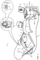
- Fig. 1 is a pictorial illustration of a system 10 for performing EP sensing, pacing and ablation procedures on a heart 12 of a living subject (e.g., patient 13).
- the system 10 comprises a catheter 14, which is percutaneously inserted by an operator 16 through the patient's 13 vascular system into a chamber or vascular structure of the heart 12.
- An operator 16 who is typically a physician, brings the catheter's distal tip 18 into contact with the heart wall.
- Electrical activation maps may then be prepared, e.g., according to the methods disclosed in U.S. Patents 6,226,542 , and 6,301,496 , and in commonly assigned U.S. Patent 6,892,091 .
- One commercial product embodying elements of the system 10 is available as the CARTO ® 3 System, available from Biosense Webster, Inc., 3333 Diamond Canyon Road, Diamond Bar, Calif. 91765.
- Areas determined to be abnormal for example, by evaluation of the electrical activation maps, can be ablated, e.g., by passage of radiofrequency electrical current through wires in the catheter to one or more electrodes at the distal tip 18.
- the catheter 14 typically comprises a handle 20, having suitable controls on the handle to enable the operator 16 to steer, position and orient the distal end of the catheter as desired for the ablation.
- the distal portion of the catheter 14 contains position sensors (not shown) that provide signals to a positioning processor 22, located in a console 24.
- Ablation energy and electrical signals can be conveyed to and from the heart 12 through an ablation electrode 32 located at or near the distal tip 18 via cable 34 to the console 24.
- Sensing electrodes 33 also connected to the console 24, are disposed generally in the distal portion of the catheter 14, and have connections to the cable 34.
- Electrocardiac signals acquired, for example, from the sensing electrodes 33, pass from the electrode 33 through the cable 34, and are digitized by suitable Analog-to-Digital Converters (ADCs), for example of a patient interface unit (PIU) (not shown), this PIU in communication with the electrodes 33 and is positioned along the cable 34, for example, proximate to the electrodes 33.
- ADCs Analog-to-Digital Converters
- PIU patient interface unit
- the resulting digital signals are referred to herein as "acquired electrocardiac signals", “acquired signals”, or “raw signals” - these terms used interchangeably herein.
- the digital signals are provided to the switching system 100, to the switch unit 110, and then to the console 24. While in the switch unit 110, the acquired digital signals are typically subjected to processing, including modification, such as digital to analog conversion, filtering, amplification and other processes.
- pacing signals and various other signals may be conveyed from the console 24 through the cable 34 (and the catheter 14) and the electrodes 32, 33 to the heart 12, through the switching system 100.
- the electrodes 32, 33 are possible.
- the ablation electrode 32 may be disposed at the distal tip 18.
- the console 24 typically contains one or more ablation power generators 25 for generating the ablation signals.
- the positioning processor 22 is an element of a positioning system 26 of the system 10 that measures location and orientation coordinates of the catheter 14.
- the positioning system 26 comprises a magnetic position tracking arrangement that determines the position and orientation of the catheter 14 by generating magnetic fields in a predefined working volume its vicinity and sensing these fields at the catheter 14 using field generating coils 28, and may include impedance measurement, as taught, for example, in U.S. Patent Application Publication 2007/0060832 .
- the positioning system 26 may be enhanced by position measurements using the impedance measurements described in the above-noted U.S. Patent 7,536,218 . In such position tracking arrangements, wire connections 35 link the console 24 with body surface electrodes 30.
- Console 24 includes a processor 24x ( Fig. 2 ), which can be a computer with appropriate signal processing circuits.
- the processor 24x is coupled to drive a monitor 29.
- the signal processing circuits in the console 24 typically receive, amplify, filter and digitize the received acquired or raw analog signals, processed by and transmitted from the switch unit 110.
- the analog signals output by switch unit 110 are received and used by the console 24 and the positioning system 26 to compute the position and orientation of the catheter 14 and to analyze the electrical signals from the electrodes 32, 33.
- the physician 16 may have to initiate the generation of pacing signals.
- the pacing signals are transmitted from the console 24 to the heart 12 over the same bidirectional line 200, represented by the cable 34, as the acquired signals.
- the pacing signals are triggered by the physician 16 on demand, for example, (by the physician 16 activating a pacing signal generator 24y ( Fig. 2 ) in the console 24.
- This activation may, for example, include the physician 16 pressing a button or other similar structure (not shown), for example, on the console 24 (or on a device in communications with the console 24), which communicates with the pacing signal generator 24y, to activate the pacing signals.
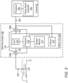
- Fig. 2 shows the switching system 100 (represented by the broken line box), in accordance with an example of the present disclosure.
- the switching system 100 includes the switch unit 110, which is positioned along a bidirectional signal carrying line 200, also known as a bidirectional line.
- the bidirectional line 200 is, for example, a single physical line, extending from an electrode 202 (in communication with the heart 12 of the patient 13) to the console 24, also known as an external console.
- the electrode 202 is representative of the multiple electrodes including those detailed above (e.g., electrodes 32, 33), and the console 24.
- the bidirectional line 200 includes the main line 120, which extends through the switch unit 110, and the bypass line 130.
- the console 24 includes a processor 24x, also known as an operations processor, for receiving and analyzing received signals from the bidirectional line 200, including the main line 120.
- the console 24, for example, also includes a pacing signal generator 24y, which is typically in communication with the processor 24x, and which may be manually triggered by the physician 16.
- the generated pacing signals are transmitted to the bidirectional line 200 to the electrode 202, via the bypass line 130, as detailed below.
- Switches 206a, 206b are, for example, positioned at the junctions of the main line 120 and the bypass line 130, beyond the switch unit 110, along the bidirectional line 200.
- the switches 206a, 206b are configured to operate by changing their states to the same state together, in unison, and at the same time, for example, contemporaneously or simultaneously.
- the switches 206a, 206b switch between states which, include, for example, a first state, where the main line 120 is enabled, activated/active, open or connected (these terms used interchangeably herein), and the bypass line 130 is disabled, deactivated or disconnected (these terms used interchangeably herein), and, a second state, where the bypass line 130 is enabled, activated/active, open, or connected (these terms used interchangeably herein), and the main line 120 is disabled, deactivated or disconnected (these terms used interchangeably herein).
- the first state may be the default state for the switches 206a, 206b.
- the main line 120 When the switches 206a, 206b are in the first state, the main line 120 is enabled, and the acquired signals travel from the electrode 202 to the console 24, via the switch unit 110. The acquired signals are typically processed in the switch unit, as detailed herein. While the main line 120 is enabled, the bypass line 130 is disabled or otherwise disconnected. Conversely, when the switches 206a, 206b are in the second state, the bypass line 130 is enabled or otherwise connected, and carries the pacing signals to the electrode 202 directly from the console 24, thus bypassing the switch unit 110. The main line 120 is disabled or otherwise disconnected, such that acquired or raw signals are cut off from traveling over the bidirectional line 200.
- the switches 206a, 206b may be either mechanical switches, or solid-state switches.
- Mechanical switches switch by physically moving or “toggling" between positions corresponding to the first and second states, respectively.
- Solid-state switches switch by electronically changing settings or resetting, the settings corresponding to the respective first and second states.
- the switch unit 110 includes a processor 210, also known as a switch unit processor, associated storage media 211, a digital to analog converter (DAC) 212 and a sensor 214, both of which communicate with a processor 210.
- the processor 210 communicates with the switches 206a, 206b over wired links.
- the switch unit 110 may include other components, such as filters and/or amplifiers for filtering and/or amplifying the signals after digital-to-analog conversion, in addition to the components described herein, depending on the signal processing that the switch unit 110 is to perform.
- the processor 210 includes one or more processors and may be a microcontroller or a central processing unit (CPU) .
- the processor 210 is programmed to control the state of the switches 206a, 206b, switching the switches 206a, 206b when appropriate, in response to signals received from the sensor 214.
- the storage/memory 211 (which in some examples is an internal memory of processor 210) stores machine executable instructions for execution by the processor 210.
- the storage/memory 211 also includes storage media for temporary storage of data.
- the storage/memory 211 also includes machine executable instructions associated with the operation of the DAC 212 and the sensor 214.
- the DAC 212 converts digital signals, such as the acquired or raw signals, received over the main line 120 of the bidirectional line 200, from the electrode 202, into analog signals.
- the now-converted analog signals are transmitted to the console 24, over the main line 120 of the bidirectional line 200.
- the sensor 214 includes a detector, which, for example, detects analog pacing signals.
- the detector is positioned along the main line 120, typically intermediate the console 24 and the switch unit 110, and for example, intermediate the console 24 and the switch 206b.
- the sensor 214 and detector are collectively referred to hereinafter as the "sensor", and represented by element number 214.
- the sensor 214 operates by continuously monitoring the main line 120 of the bidirectional line 200 for pacing signals, and instantaneously reporting any detected pacing signals to the processor 210.
- the detection of the pacing signals, as reported to and obtained by the processor 210, allows the processor 210 to take action by signaling the switches 206a, 206b to change (switch) their states, from the first state to the second state, to enable the bypass line 130, or alternately, maintain the switches 206a, 206b at the second state, to keep the bypass line 130 enabled, should the switches 206a, 206b already be at the second state.
- the switching system 100 disconnects or otherwise disables the main line 120 over which the acquired or raw signals travel from the heart 12 to the console 24, through the switch unit 110.
- the disconnecting is immediate, e.g., instantaneously, and is immediately, e.g., instantaneously followed by the switching unit 110, enabling or otherwise connecting (opening) a bypass line 130, over which the pacing signals travel.
- the pacing signals travel directly over the bypass line 130, from the console 24 to the electrodes at the heart 12.
- the pacing signals bypass and thus avoid the switch unit 110, and signals travel over the bypass line 130 directly to catheter 14, bypassing switching unit 110 entirely.
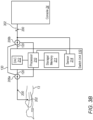
- FIG. 3A , 3B and 3C illustrate example operations for the switching system 100.
- Fig. 3A illustrates operation of the switching system 100, where acquired signals 300 are traveling from the electrode 202 to the console 24, through the switch unit 110, over the main line 120 of the bidirectional line 200.
- the switches 206a, 206b are in the first state, such that the main line 120 of the bidirectional line 200 is enabled and open, to allow the aforementioned signal 300 flow.
- the acquired signals are, for example, digital signals (as obtained from the electrode 202 by an analog to digital converter of the PIU (not shown) associated and in communication with the electrode 202 along the bidirectional line 200 portion proximate to the electrode 202), these digital signals are processed in switch unit 110, by at least being converted to analog signals, by the DAC converter 212.
- pacing signal generation and transmission has been started or initiated by the physician 16 (for example, pressing a button on the console 24 or on a device in communications with the console 24 to activate the pacing signal generator 24y).
- the pacing signals 302 are generated by a generator 24y in the console 24 and transmitted by a transmitter (not shown) in the console 24, over the bidirectional line 200.
- the pacing signals 302 are, for example, analog signals, which once triggered at the console 24, are to immediately reach the patient 13 via the electrode 202 (traveling over an uninterrupted electrical connection in the bidirectional line 200).
- the pacing signals 302 are detected by the sensor 214.
- the sensor 214 signals the processor 210 that pacing signals 302 have been detected in the bidirectional line 200.
- the processor 210 responds to these received signals, by signaling the switches 206a, 206b, to switch from the first state, to the second state, enabling or opening the bypass line 130 of the bidirectional line 200.
- the pacing signals 302 travel directly from the console 24 to reach the electrode 202, bypassing the switch unit 110.
- the switching to the bypass line 130 has caused the switches 206a, 206b to switch, resulting in the disabling or otherwise disconnecting of the main line 120 of the bidirectional line 200, such that acquired signals are cut off from flowing through the main line 120 of the bidirectional line 200.
- the pacing signals 302 continue to be generated by the console 24, and are detected by the and the sensor 214, the sensor 214 continues to signal the processor 210 of the presence of the pacing signals 302.
- the switches 206a, 206b are maintained in the second state, where the bypass line 130 remains enabled and open, allowing the pacing signals to travel directly from the console 24 to the electrode 202.
- the pacing signals 302 are no longer detected by the sensor 214, for example, for a predetermined amount of time, the sensor 214 signals this condition to the processor 210.
- the processor 210 responds by signaling the switches 206a, 206b to switch from the second state to the first state, where the main line 120 is again enabled, and the bypass line 130 is disabled or disconnected, as shown, for example, in Fig. 3A .
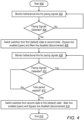
- Fig. 4 is a flow diagram of an example process performed by the switching system 100.
- the example process allows for the immediate transmission of pacing signals, upon being manually triggered or activated by the physician 16.
- the pacing signals are generated at a console 24 and transmitted to an electrode 202 at the catheter 14 at the patient's heart 12. Once the pacing signals are no longer being transmitted, the switching system 100 reverts to its previous state, prior to the pacing signals having been detected.
- the process is, for example, performed automatically and in real time, and may include manual subprocesses. The process may be performed for as long as desired.
- the process begins at a START block 400, where the switches 206a, 206b, are in the first state, which is also the default state here, as shown, for example, in Fig. 3A .
- the digital to analog converter of the PIU (not shown) associated with the electrode 202 is transmitting acquired signals (obtained by the electrode 202) to the console 24, via the switch unit 110, over the enabled main line 120 of the bidirectional line 200.
- the acquired signals upon reaching the switch unit 110 are processed, for example, by being converted to analog signals, by the DAC 212.
- the bypass line 130 is disabled and disconnected.
- the process moves to block 402, where the sensor 214 monitors the bidirectional line 200, proximate to the console 24 for pacing signals, transmitted from the console 24.
- the monitoring is, for example, continuous.
- the process moves to block 404, where the sensor 214 determines whether pacing signals are detected. If no, the sensor 214, for example, does not signal the processor 210, and the switch 206a, 206b state is maintained in the first or default state. The process returns to block 404, from where it resumes.
- the sensor 214 detects pacing signals in the bidirectional line 200, which are, for example, traveling from the console 24 toward the switch unit 110, as shown, for example, in Fig. 3B , the sensor 214 signals this information to the processor 210.
- the processor 210 signals the switches 206a, 206b to instantaneously change (switch) states, from the first state, to the second state, at block 406, and as shown, for example, in Fig. 3C .
- the bypass line 130 is immediately enabled or open, and pacing signals are transmitted directly from the console 24 to the electrode 202, avoiding the switch unit 110.
- the process moves to block 408, where the sensor 214 monitors the bidirectional line 200, proximate to the console 24 for pacing signals, transmitted from the console 24.
- the monitoring is, for example, continuous.
- the process moves to block 410, where it is determined, by the sensor 214, whether pacing signals are being transmitted (and generated) from the console 24. If yes, the process returns to block 408, from where it resumes.
- the switch 206a, 206b state at the second state is maintained.
- the processor 210 determines whether pacing signals have not been detected for a predetermined time period. For example, the processor 210 may not have received any signals from the sensor 214 indicating the detection of pacing signals. If no at block 412, the time period has not expired, and the process moves to block 410, from where the process resumes.
- the process moves to block 414, where the processor 210 signals the switches 206a, 206b to change (switch) from the second state to the first state, which is, for example, the default state.
- This switching returns the switching system 100 to its previous or default state, as the pacing signals are no longer being transmitted, and the main line 120 is again enabled, for carrying the acquired signals, from the electrode 202 to the console 24, via the switch unit 110, shown, for example, in Fig. 3A .
- the aforementioned disclosed subject matter may, for example, also be in the form of a computer software product.
- the product comprises, for example, a tangible non-transitory computer-readable medium in which program instructions are stored, which instructions, when read by a processor 210, cause the processor 210 to signal switches 206a, 206b to switch to the same state together, in order to enable and open a bypass line 130 in a bidirectional line 200, such that pacing signals may be transmitted directly from the console 24 to the electrode, rapidly and efficiently, upon being triggered or otherwise activated manually by the physician 16.
- the bypassing of the switch unit 110 avoids any processing delays in the switch unit 110.
- the main line 120 over which acquired signals travel from the electrode 202 to the console 24, is disabled and disconnected.
- the switching system comprises: a switch unit (110) for communicating with a bidirectional line (200), the bidirectional line (200) configured for extending from an electrode (202) at the heart (12) of the subject (13) to an external console (24).
- the bidirectional line (200) comprises: a main line (120), extending through the switch unit (110), for carrying signals comprising acquired signals from the electrode (202) to the external console (24); and, a bypass line (130), extending outside of the switch unit (110) for carrying signals comprising pacing signals from the external console (24) to the electrode (202).
- the switching system (110) also comprises: a first switch (206a) and a second switch (206b) each in communication with the switch unit (110), each of the first switch (206a) and the second switch (206b) in communication with the main line (120) and the bypass line (130), the first switch (206a) and the second switch (206b) changeable between: 1) a first state, where the main line (120) is enabled for carrying the acquired signals, and the bypass line (130) is disabled, and, 2) a second state, where the bypass line (130) is enabled for carrying the pacing signals and the main line (120) is disabled.
- a sensor in communication with the switch unit processor (210)
- the sensor (214) configured for sensing at least the presence of detected pacing signals on the bidirectional line (200) proximate to the external console (24), and to indicate the detected pacing signals to the switch unit processor (210), causing the switch unit processor (210) to signal the first switch (206a) and the second switch (206b) to change the state, between the first state and
- DAC digital to analog signal converter
- the method comprises: providing a switching system (100) along the bidirectional line (200).
- the switching system (100) comprises: a switch unit (110) for communicating with the bidirectional line (200), the bidirectional line (200) configured for extending from the electrode (202) at the heart (12) of the patient (13) to the external console (24).
- the bidirectional line (200) comprises: a main line (120), extending through the switch unit (110), for carrying signals comprising acquired signals; and, a bypass line (130), extending outside of the switch unit (110) for carrying signals comprising pacing signals.
- the switching system (100) also comprises: a first switch (206a) and a second switch (206b) each in communication with the switch unit (110), each of the first switch (206a) and the second switch (206b) in communication with the main line (120) and the bypass line (130), the first switch (206a) and the second switch (206b) changeable between: 1) a first state, where the main line (120) is enabled for carrying the acquired signals, and the bypass line (130) is disabled, and, 2) a second state, where the bypass line (130) is enabled for carrying the pacing signals and the main line (120) is disabled.
- the method also comprises: detecting at least one pacing signal along a portion of the bidirectional line (200) proximate to the external console (24); and, in response to the detected at least one pacing signal, changing the state of the first switch (206a) and the second switch (206b) from the first state to the second state.
- Example 9 wherein the response to the detected at least one pacing signal includes maintaining the first switch (206a) and the second switch (206b) at the second state if the existing state is the second state.
- Example 9 The method of Example 9 or Example 10, wherein the first switch (206a) and the second switch (206b) are maintained at the second state until the at least one pacing signal is not detected for a predetermined time period.
- Example 9 The method of any of Example 9 to Example 11, wherein, the state of the first switch (206a) and the second switch (206b) are changed from the second state to the first state when the at least one pacing signal is not detected for at least a predetermined time period.
- Example 9 The method of any of Example 9 to Example 12, wherein the detecting the at least one pacing signal is by at least one sensor (214).
- Example 9 The method of any of Example 9 to Example 13, wherein at least a portion of the at least one sensor (214) is in communication with the bidirectional line (200) portion proximate to the external console (24).
- Example 9 to Example 14 wherein the response to the detected at least one pacing signal, includes at least one processor (210) receiving at least one signal that the at least one pacing signal has been detected, and the at least one processor (210) signaling the first switch (206a) and the second switch (206b) to change the state of the first switch (206a) and the second switch (206b) from the first state to the second state.
- Example 9 The method of any of Example 9 to Example 15, wherein the detecting the at least one pacing signal along the bidirectional line (200) portion proximate to the external console (24) includes monitoring the bidirectional line (200) portion.
Landscapes
- Health & Medical Sciences (AREA)
- Life Sciences & Earth Sciences (AREA)
- Engineering & Computer Science (AREA)
- Public Health (AREA)
- Animal Behavior & Ethology (AREA)
- Veterinary Medicine (AREA)
- General Health & Medical Sciences (AREA)
- Biomedical Technology (AREA)
- Heart & Thoracic Surgery (AREA)
- Surgery (AREA)
- Nuclear Medicine, Radiotherapy & Molecular Imaging (AREA)
- Medical Informatics (AREA)
- Molecular Biology (AREA)
- Biophysics (AREA)
- Physics & Mathematics (AREA)
- Pathology (AREA)
- Radiology & Medical Imaging (AREA)
- Cardiology (AREA)
- Plasma & Fusion (AREA)
- Otolaryngology (AREA)
- Robotics (AREA)
- Oral & Maxillofacial Surgery (AREA)
- Pulmonology (AREA)
- Anesthesiology (AREA)
- Hematology (AREA)
- Vascular Medicine (AREA)
- Physiology (AREA)
- Electrotherapy Devices (AREA)
- Measurement And Recording Of Electrical Phenomena And Electrical Characteristics Of The Living Body (AREA)
- Surgical Instruments (AREA)
Abstract
Description
- The present disclosure relates generally to switching systems for signals during cardiac procedures, and particularly to switching systems for switching between acquired electrocardiac signals and pacing signals during cardiac procedures.
- Electrocardiac signals acquired during a cardiac procedure, such as Electro-Physiological (EP) sensing procedure, are routed from electrodes at the heart of a patient to a system console, where the signals are recorded, analyzed, and displayed. The signals may be routed via a switching system which includes a digital-to-analog converter (DAC), which accepts acquired or "raw" digital signals from the electrodes and converts them into analog signals. The switching system may also perform other functions such as filtering and amplification. This manipulation overcomes the legacy problem that the console is only designed to accept a limited number of acquired signals.
- The present disclosed subject matter will be more fully understood from the following detailed description of the examples thereof, taken together with the drawings, where corresponding or like reference numbers or characters indicate corresponding or like elements, in which:
-
Fig. 1 is a schematic pictorial illustration of a cardiac EP sensing, mapping, pacing and ablation system used with a patient, in accordance with examples of the present disclosure; -
Fig. 2 is a diagram of a switching system in an example use with the cardiac system ofFig. 1 , in accordance with the present disclosure; -
Fig. 3A is a diagram of the switching system in an example use with the cardiac system ofFig. 1 , where acquired electrocardiac signals are passing from a patient to a console; -
Fig. 3B is a diagram of the switching system in an example use with the cardiac system ofFig. 1 , where acquired electrocardiac signals are passing from the patient to the console, and the switching system has detected a pacing signal; -
Fig. 3C is a diagram of the switching system in an example use with the cardiac system ofFig. 1 , where pacing signals are being transmitted from the console to the patient; and -
Fig. 4 is a flow chart that schematically illustrates an exemplary operational process performed by the switching system ofFigs. 2 and3A-3C , in accordance with an example of the present disclosure. - The present disclosed subject matter provides switching systems and methods for handling the high (and constantly growing) numbers of signals that are acquired over short time periods, e.g., simultaneously, and passed from electrodes at the heart the patient to the console, while allowing pacing to proceed as normal.
- The disclosed subject matter provides a switching system which includes a switch unit, which performs operations such as digital to analog signal conversion (by a digital to analog converted (DAC)) and other signal processing operations. The switching system is positioned along a bidirectional signal carrying line, also known as a bidirectional line. The bidirectional line extending between a catheter at the heart, the catheter including, for example, an electrode, and a console. The bidirectional line includes a main line, extending through the switch unit and a bypass line, around the switch unit, the main line and bypass lines enabled and disabled by switches, with the switches at the junctions of the main line and the bypass line. Pacing signals generated in the console cannot pass through the DAC and/or other signal processors of the switch unit, and accordingly, have to travel over the bypass line, which must be enabled by the switches changing states. The enabled bypass line provides an uninterrupted electrical connection from the console to the catheter, allowing for safe operation of the pacing signals.
-
Fig. 1 is a pictorial illustration of asystem 10 for performing EP sensing, pacing and ablation procedures on aheart 12 of a living subject (e.g., patient 13). Thesystem 10 comprises acatheter 14, which is percutaneously inserted by anoperator 16 through the patient's 13 vascular system into a chamber or vascular structure of theheart 12. Anoperator 16, who is typically a physician, brings the catheter'sdistal tip 18 into contact with the heart wall. - Electrical activation maps may then be prepared, e.g., according to the methods disclosed in
U.S. Patents 6,226,542 , and6,301,496 , and in commonly assignedU.S. Patent 6,892,091 . One commercial product embodying elements of thesystem 10 is available as the CARTO®3 System, available from Biosense Webster, Inc., 3333 Diamond Canyon Road, Diamond Bar, Calif. 91765. - Areas determined to be abnormal, for example, by evaluation of the electrical activation maps, can be ablated, e.g., by passage of radiofrequency electrical current through wires in the catheter to one or more electrodes at the
distal tip 18. - The
catheter 14 typically comprises ahandle 20, having suitable controls on the handle to enable theoperator 16 to steer, position and orient the distal end of the catheter as desired for the ablation. To aid theoperator 16, the distal portion of thecatheter 14 contains position sensors (not shown) that provide signals to apositioning processor 22, located in aconsole 24. - Ablation energy and electrical signals can be conveyed to and from the
heart 12 through anablation electrode 32 located at or near thedistal tip 18 viacable 34 to theconsole 24.Sensing electrodes 33, also connected to theconsole 24, are disposed generally in the distal portion of thecatheter 14, and have connections to thecable 34. - Electrocardiac signals, acquired, for example, from the
sensing electrodes 33, pass from theelectrode 33 through thecable 34, and are digitized by suitable Analog-to-Digital Converters (ADCs), for example of a patient interface unit (PIU) (not shown), this PIU in communication with theelectrodes 33 and is positioned along thecable 34, for example, proximate to theelectrodes 33. The resulting digital signals are referred to herein as "acquired electrocardiac signals", "acquired signals", or "raw signals" - these terms used interchangeably herein. The digital signals are provided to theswitching system 100, to theswitch unit 110, and then to theconsole 24. While in theswitch unit 110, the acquired digital signals are typically subjected to processing, including modification, such as digital to analog conversion, filtering, amplification and other processes. - In addition, pacing signals and various other signals may be conveyed from the
console 24 through the cable 34 (and the catheter 14) and theelectrodes heart 12, through theswitching system 100. Many configurations of theelectrodes ablation electrode 32 may be disposed at thedistal tip 18. Theconsole 24 typically contains one or moreablation power generators 25 for generating the ablation signals. - The
positioning processor 22 is an element of apositioning system 26 of thesystem 10 that measures location and orientation coordinates of thecatheter 14. In one example, thepositioning system 26 comprises a magnetic position tracking arrangement that determines the position and orientation of thecatheter 14 by generating magnetic fields in a predefined working volume its vicinity and sensing these fields at thecatheter 14 using field generatingcoils 28, and may include impedance measurement, as taught, for example, inU.S. Patent Application Publication 2007/0060832 . Thepositioning system 26 may be enhanced by position measurements using the impedance measurements described in the above-notedU.S. Patent 7,536,218 . In such position tracking arrangements,wire connections 35 link theconsole 24 withbody surface electrodes 30. - As noted above, the
catheter 14 is coupled to theconsole 24, which enables theoperator 16 to observe and regulate the functions of thecatheter 14.Console 24 includes aprocessor 24x (Fig. 2 ), which can be a computer with appropriate signal processing circuits. Theprocessor 24x is coupled to drive amonitor 29. The signal processing circuits in theconsole 24 typically receive, amplify, filter and digitize the received acquired or raw analog signals, processed by and transmitted from theswitch unit 110. The analog signals output byswitch unit 110 are received and used by theconsole 24 and thepositioning system 26 to compute the position and orientation of thecatheter 14 and to analyze the electrical signals from theelectrodes - At times during the procedure, such as abnormality in the procedure or stoppage of the heartbeat, as detected automatically by the
system 10, or manually by thephysician 16, thephysician 16 may have to initiate the generation of pacing signals. The pacing signals are transmitted from theconsole 24 to theheart 12 over the samebidirectional line 200, represented by thecable 34, as the acquired signals. The pacing signals are triggered by thephysician 16 on demand, for example, (by thephysician 16 activating apacing signal generator 24y (Fig. 2 ) in theconsole 24. This activation may, for example, include thephysician 16 pressing a button or other similar structure (not shown), for example, on the console 24 (or on a device in communications with the console 24), which communicates with thepacing signal generator 24y, to activate the pacing signals. -
Fig. 2 shows the switching system 100 (represented by the broken line box), in accordance with an example of the present disclosure. Theswitching system 100 includes theswitch unit 110, which is positioned along a bidirectionalsignal carrying line 200, also known as a bidirectional line. Thebidirectional line 200, is, for example, a single physical line, extending from an electrode 202 (in communication with theheart 12 of the patient 13) to theconsole 24, also known as an external console. Theelectrode 202 is representative of the multiple electrodes including those detailed above (e.g.,electrodes 32, 33), and theconsole 24. Thebidirectional line 200 includes themain line 120, which extends through theswitch unit 110, and thebypass line 130. - The
console 24 includes aprocessor 24x, also known as an operations processor, for receiving and analyzing received signals from thebidirectional line 200, including themain line 120. Theconsole 24, for example, also includes apacing signal generator 24y, which is typically in communication with theprocessor 24x, and which may be manually triggered by thephysician 16. The generated pacing signals are transmitted to thebidirectional line 200 to theelectrode 202, via thebypass line 130, as detailed below. -
Switches main line 120 and thebypass line 130, beyond theswitch unit 110, along thebidirectional line 200. Theswitches - The
switches main line 120 is enabled, activated/active, open or connected (these terms used interchangeably herein), and thebypass line 130 is disabled, deactivated or disconnected (these terms used interchangeably herein), and, a second state, where thebypass line 130 is enabled, activated/active, open, or connected (these terms used interchangeably herein), and themain line 120 is disabled, deactivated or disconnected (these terms used interchangeably herein). For example, the first state may be the default state for theswitches - When the
switches main line 120 is enabled, and the acquired signals travel from theelectrode 202 to theconsole 24, via theswitch unit 110. The acquired signals are typically processed in the switch unit, as detailed herein. While themain line 120 is enabled, thebypass line 130 is disabled or otherwise disconnected. Conversely, when theswitches bypass line 130 is enabled or otherwise connected, and carries the pacing signals to theelectrode 202 directly from theconsole 24, thus bypassing theswitch unit 110. Themain line 120 is disabled or otherwise disconnected, such that acquired or raw signals are cut off from traveling over thebidirectional line 200. - The
switches - The
switch unit 110 includes aprocessor 210, also known as a switch unit processor, associatedstorage media 211, a digital to analog converter (DAC) 212 and asensor 214, both of which communicate with aprocessor 210. Theprocessor 210 communicates with theswitches switch unit 110 may include other components, such as filters and/or amplifiers for filtering and/or amplifying the signals after digital-to-analog conversion, in addition to the components described herein, depending on the signal processing that theswitch unit 110 is to perform. - The
processor 210 includes one or more processors and may be a microcontroller or a central processing unit (CPU) . Theprocessor 210 is programmed to control the state of theswitches switches sensor 214. - The storage/memory 211 (which in some examples is an internal memory of processor 210) stores machine executable instructions for execution by the
processor 210. The storage/memory 211 also includes storage media for temporary storage of data. The storage/memory 211 also includes machine executable instructions associated with the operation of theDAC 212 and thesensor 214. - The
DAC 212 converts digital signals, such as the acquired or raw signals, received over themain line 120 of thebidirectional line 200, from theelectrode 202, into analog signals. The now-converted analog signals are transmitted to theconsole 24, over themain line 120 of thebidirectional line 200. - The
sensor 214 includes a detector, which, for example, detects analog pacing signals. The detector is positioned along themain line 120, typically intermediate theconsole 24 and theswitch unit 110, and for example, intermediate theconsole 24 and theswitch 206b. Thesensor 214 and detector are collectively referred to hereinafter as the "sensor", and represented byelement number 214. - For example, the
sensor 214 operates by continuously monitoring themain line 120 of thebidirectional line 200 for pacing signals, and instantaneously reporting any detected pacing signals to theprocessor 210. The detection of the pacing signals, as reported to and obtained by theprocessor 210, allows theprocessor 210 to take action by signaling theswitches bypass line 130, or alternately, maintain theswitches bypass line 130 enabled, should theswitches - For example, once a pacing signal is detected in the
switching system 100 by theswitching unit 110, theswitching system 100 disconnects or otherwise disables themain line 120 over which the acquired or raw signals travel from theheart 12 to theconsole 24, through theswitch unit 110. The disconnecting is immediate, e.g., instantaneously, and is immediately, e.g., instantaneously followed by theswitching unit 110, enabling or otherwise connecting (opening) abypass line 130, over which the pacing signals travel. The pacing signals travel directly over thebypass line 130, from theconsole 24 to the electrodes at theheart 12. As a result of the now-enabledbypass line 130, the pacing signals bypass and thus avoid theswitch unit 110, and signals travel over thebypass line 130 directly tocatheter 14, bypassingswitching unit 110 entirely. - Attention is now directed to
Figs. 3A ,3B and3C , which illustrate example operations for theswitching system 100. -
Fig. 3A illustrates operation of theswitching system 100, where acquired signals 300 are traveling from theelectrode 202 to theconsole 24, through theswitch unit 110, over themain line 120 of thebidirectional line 200. Theswitches main line 120 of thebidirectional line 200 is enabled and open, to allow theaforementioned signal 300 flow. As the acquired signals are, for example, digital signals (as obtained from theelectrode 202 by an analog to digital converter of the PIU (not shown) associated and in communication with theelectrode 202 along thebidirectional line 200 portion proximate to the electrode 202), these digital signals are processed inswitch unit 110, by at least being converted to analog signals, by theDAC converter 212. - In
Fig. 3B , pacing signal generation and transmission has been started or initiated by the physician 16 (for example, pressing a button on theconsole 24 or on a device in communications with theconsole 24 to activate thepacing signal generator 24y). The pacing signals 302 are generated by agenerator 24y in theconsole 24 and transmitted by a transmitter (not shown) in theconsole 24, over thebidirectional line 200. The pacing signals 302 are, for example, analog signals, which once triggered at theconsole 24, are to immediately reach thepatient 13 via the electrode 202 (traveling over an uninterrupted electrical connection in the bidirectional line 200). In this figure, the pacing signals 302 are detected by thesensor 214. Thesensor 214 signals theprocessor 210 that pacing signals 302 have been detected in thebidirectional line 200. Theprocessor 210 responds to these received signals, by signaling theswitches bypass line 130 of thebidirectional line 200. - As shown in
Fig. 3C , with thebypass line 130 enabled, the pacing signals 302 travel directly from theconsole 24 to reach theelectrode 202, bypassing theswitch unit 110. The switching to thebypass line 130 has caused theswitches main line 120 of thebidirectional line 200, such that acquired signals are cut off from flowing through themain line 120 of thebidirectional line 200. - As the pacing signals 302 continue to be generated by the
console 24, and are detected by the and thesensor 214, thesensor 214 continues to signal theprocessor 210 of the presence of the pacing signals 302. In response, theswitches bypass line 130 remains enabled and open, allowing the pacing signals to travel directly from theconsole 24 to theelectrode 202. - Once the pacing signals 302 are no longer detected by the
sensor 214, for example, for a predetermined amount of time, thesensor 214 signals this condition to theprocessor 210. Theprocessor 210 responds by signaling theswitches main line 120 is again enabled, and thebypass line 130 is disabled or disconnected, as shown, for example, inFig. 3A . -
Fig. 4 is a flow diagram of an example process performed by theswitching system 100. The example process allows for the immediate transmission of pacing signals, upon being manually triggered or activated by thephysician 16. The pacing signals are generated at aconsole 24 and transmitted to anelectrode 202 at thecatheter 14 at the patient'sheart 12. Once the pacing signals are no longer being transmitted, theswitching system 100 reverts to its previous state, prior to the pacing signals having been detected. In this process, reference is made to theswitching system 100 elements, as described above. The process is, for example, performed automatically and in real time, and may include manual subprocesses. The process may be performed for as long as desired. - The process begins at a
START block 400, where theswitches Fig. 3A . Here, the digital to analog converter of the PIU (not shown) associated with theelectrode 202 is transmitting acquired signals (obtained by the electrode 202) to theconsole 24, via theswitch unit 110, over the enabledmain line 120 of thebidirectional line 200. The acquired signals, upon reaching theswitch unit 110 are processed, for example, by being converted to analog signals, by theDAC 212. During the transmission of the acquired signals, thebypass line 130 is disabled and disconnected. - The process moves to block 402, where the
sensor 214 monitors thebidirectional line 200, proximate to theconsole 24 for pacing signals, transmitted from theconsole 24. The monitoring is, for example, continuous. - The process moves to block 404, where the
sensor 214 determines whether pacing signals are detected. If no, thesensor 214, for example, does not signal theprocessor 210, and theswitch - However, at
block 404, should thesensor 214 detect pacing signals in thebidirectional line 200, which are, for example, traveling from theconsole 24 toward theswitch unit 110, as shown, for example, inFig. 3B , thesensor 214 signals this information to theprocessor 210. Theprocessor 210 signals theswitches block 406, and as shown, for example, inFig. 3C . With theswitches bypass line 130 is immediately enabled or open, and pacing signals are transmitted directly from theconsole 24 to theelectrode 202, avoiding theswitch unit 110. - The process moves to block 408, where the
sensor 214 monitors thebidirectional line 200, proximate to theconsole 24 for pacing signals, transmitted from theconsole 24. The monitoring is, for example, continuous. - The process moves to block 410, where it is determined, by the
sensor 214, whether pacing signals are being transmitted (and generated) from theconsole 24. If yes, the process returns to block 408, from where it resumes. Theswitch - If no at
block 410, pacing signals are not being detected, and the process moves to block 412. Atblock 412, theprocessor 210 determines whether pacing signals have not been detected for a predetermined time period. For example, theprocessor 210 may not have received any signals from thesensor 214 indicating the detection of pacing signals. If no atblock 412, the time period has not expired, and the process moves to block 410, from where the process resumes. - At
block 412, should the time period have expired, the process moves to block 414, where theprocessor 210 signals theswitches switching system 100 to its previous or default state, as the pacing signals are no longer being transmitted, and themain line 120 is again enabled, for carrying the acquired signals, from theelectrode 202 to theconsole 24, via theswitch unit 110, shown, for example, inFig. 3A . - From
block 414, the process moves to block 416, where it ends. The process may be repeated as desired. - Although the examples described herein mainly address switching in electrocardiac signal and pacing signal carrying lines, the methods and systems described herein can also be used in other switching applications.
- The aforementioned disclosed subject matter may, for example, also be in the form of a computer software product. The product comprises, for example, a tangible non-transitory computer-readable medium in which program instructions are stored, which instructions, when read by a
processor 210, cause theprocessor 210 to signalswitches bypass line 130 in abidirectional line 200, such that pacing signals may be transmitted directly from theconsole 24 to the electrode, rapidly and efficiently, upon being triggered or otherwise activated manually by thephysician 16. The bypassing of theswitch unit 110 avoids any processing delays in theswitch unit 110. During the time thebypass line 130 is enabled or open, themain line 120, over which acquired signals travel from theelectrode 202 to theconsole 24, is disabled and disconnected. - A switching system (100) for use in a cardiac procedure on a subject (13). The switching system comprises: a switch unit (110) for communicating with a bidirectional line (200), the bidirectional line (200) configured for extending from an electrode (202) at the heart (12) of the subject (13) to an external console (24). The bidirectional line (200) comprises: a main line (120), extending through the switch unit (110), for carrying signals comprising acquired signals from the electrode (202) to the external console (24); and, a bypass line (130), extending outside of the switch unit (110) for carrying signals comprising pacing signals from the external console (24) to the electrode (202). The switching system (110) also comprises: a first switch (206a) and a second switch (206b) each in communication with the switch unit (110), each of the first switch (206a) and the second switch (206b) in communication with the main line (120) and the bypass line (130), the first switch (206a) and the second switch (206b) changeable between: 1) a first state, where the main line (120) is enabled for carrying the acquired signals, and the bypass line (130) is disabled, and, 2) a second state, where the bypass line (130) is enabled for carrying the pacing signals and the main line (120) is disabled.
- The switching system (100) of Example 1, wherein the first switch (206a) and the second switch (206b) are configured for switching together between the first state and the second state.
- The switching system (100) of any of Example 1 or Example 2, wherein the switch unit (110) comprises: at least one switch unit processor (210) in communication with the first switch (206a) and the second switch (206b), the switch unit processor (210) programmed to signal the first switch (206a) and the second switch (206b) to: change the state, between the first state and the second state, or, maintain the state at the first state or the second state.
- The switching system (100) of any of Example 1 to Example 3, wherein the switch unit (110) additionally comprises: a sensor (214) in communication with the switch unit processor (210), the sensor (214) configured for sensing at least the presence of detected pacing signals on the bidirectional line (200) proximate to the external console (24), and to indicate the detected pacing signals to the switch unit processor (210), causing the switch unit processor (210) to signal the first switch (206a) and the second switch (206b) to change the state, between the first state and the second state, or maintain the state, at the first state or the second state.
- The switching system (100) of any of Example 1 to Example 4, wherein the first switch (206a) and the second switch (206b) are along the bidirectional line (200) beyond the switch unit (110).
- The switching system (100) of any of Example 1 to Example 5, wherein the first switch (206a) and the second switch (206b) are each at a junction of the main line (120) and the bypass line (130).
- The switching system (100) of any of Example 1 to Example 6, wherein the first switch (206a) and the second switch (206b) both comprise either mechanical switches or solid-state switches.
- The switching system (100) of any of Example 1 to Example 7, wherein the switch unit (110) additionally comprises: a digital to analog signal converter (DAC) (212) in communication with the main line (120) of the bidirectional line (200).
- A method for switching signals carried along a bidirectional line (200) between an electrode (202) at the heart (12) of a patient (13) and an external console (24). The method comprises: providing a switching system (100) along the bidirectional line (200). The switching system (100) comprises: a switch unit (110) for communicating with the bidirectional line (200), the bidirectional line (200) configured for extending from the electrode (202) at the heart (12) of the patient (13) to the external console (24). The bidirectional line (200) comprises: a main line (120), extending through the switch unit (110), for carrying signals comprising acquired signals; and, a bypass line (130), extending outside of the switch unit (110) for carrying signals comprising pacing signals. The switching system (100) also comprises: a first switch (206a) and a second switch (206b) each in communication with the switch unit (110), each of the first switch (206a) and the second switch (206b) in communication with the main line (120) and the bypass line (130), the first switch (206a) and the second switch (206b) changeable between: 1) a first state, where the main line (120) is enabled for carrying the acquired signals, and the bypass line (130) is disabled, and, 2) a second state, where the bypass line (130) is enabled for carrying the pacing signals and the main line (120) is disabled. The method also comprises: detecting at least one pacing signal along a portion of the bidirectional line (200) proximate to the external console (24); and, in response to the detected at least one pacing signal, changing the state of the first switch (206a) and the second switch (206b) from the first state to the second state.
- The method of Example 9, wherein the response to the detected at least one pacing signal includes maintaining the first switch (206a) and the second switch (206b) at the second state if the existing state is the second state.
- The method of Example 9 or Example 10, wherein the first switch (206a) and the second switch (206b) are maintained at the second state until the at least one pacing signal is not detected for a predetermined time period.
- The method of any of Example 9 to Example 11, wherein, the state of the first switch (206a) and the second switch (206b) are changed from the second state to the first state when the at least one pacing signal is not detected for at least a predetermined time period.
- The method of any of Example 9 to Example 12, wherein the detecting the at least one pacing signal is by at least one sensor (214).
- The method of any of Example 9 to Example 13, wherein at least a portion of the at least one sensor (214) is in communication with the bidirectional line (200) portion proximate to the external console (24).
- The method of any of Example 9 to Example 14, wherein the response to the detected at least one pacing signal, includes at least one processor (210) receiving at least one signal that the at least one pacing signal has been detected, and the at least one processor (210) signaling the first switch (206a) and the second switch (206b) to change the state of the first switch (206a) and the second switch (206b) from the first state to the second state.
- The method of any of Example 9 to Example 15, wherein the detecting the at least one pacing signal along the bidirectional line (200) portion proximate to the external console (24) includes monitoring the bidirectional line (200) portion.
- The method of any of Example 9 to Example 16, wherein the monitoring is continuous.
- The method of any of Example 9 to Example 17, wherein the first switch (206a) and the second switch (206b) are changeable between the first state and the second state comprising: the first switch (206a) and the second switch (206b) switching together between the first state and the second state.
- It will thus be appreciated that the examples described above are not limited to what has been particularly shown and described hereinabove. Rather, the scope of the present disclosure includes both combinations and sub-combinations of the various features described hereinabove, as well as variations and modifications thereof which would occur to persons skilled in the art upon reading the foregoing description and which are not disclosed in the prior art. Documents incorporated by reference in the present patent application are to be considered an integral part of the application except that to the extent any terms are defined in these incorporated documents in a manner that conflicts with the definitions made explicitly or implicitly in the present specification, only the definitions in the present specification should be considered.
Claims (18)
- A switching system (100) for use in a cardiac procedure on a subject (13) comprising:a switch unit (110) for communicating with a bidirectional line (200), the bidirectional line (200) configured for extending from an electrode (202) at the heart (12) of the subject (13) to an external console (24), the bidirectional line (200) comprising:a main line (120), extending through the switch unit (110), for carrying signals comprising acquired signals from the electrode (202) to the external console (24); anda bypass line (130), extending outside of the switch unit (110) for carrying signals comprising pacing signals from the external console (24) to the electrode (202); anda first switch (206a) and a second switch (206b) each in communication with the switch unit (110), each of the first switch (206a) and the second switch (206b) in communication with the main line (120) and the bypass line (130), the first switch (206a) and the second switch (206b) changeable between: 1) a first state, where the main line (120) is enabled for carrying the acquired signals, and the bypass line (130) is disabled, and, 2) a second state, where the bypass line (130) is enabled for carrying the pacing signals and the main line (120) is disabled.
- The switching system (100) of claim 1, wherein the first switch (206a) and the second switch (206b) are configured for switching together between the first state and the second state.
- The switching system (100) of claim 1 or claim 2, wherein the switch unit (110) comprises: at least one switch unit processor (210) in communication with the first switch (206a) and the second switch (206b), the switch unit processor (210) programmed to signal the first switch (206a) and the second switch (206b) to: change the state, between the first state and the second state, or, maintain the state at the first state or the second state.
- The switching system (100) of claim 3, wherein the switch unit (110) additionally comprises:
a sensor (214) in communication with the switch unit processor (210), the sensor (214) configured for sensing at least the presence of detected pacing signals on the bidirectional line (200) proximate to the external console (24), and to indicate the detected pacing signals to the switch unit processor (210), causing the switch unit processor (210) to signal the first switch (206a) and the second switch (206b) to change the state, between the first state and the second state, or maintain the state, at the first state or the second state. - The switching system (100) of any preceding claim, wherein the first switch (206a) and the second switch (206b) are along the bidirectional line (200) beyond the switch unit (110).
- The switching system (100) of claim 5, wherein the first switch (206a) and the second switch (206b) are each at a junction of the main line (120) and the bypass line (130) .
- The switching system (100) of any preceding claim, wherein the first switch (206a) and the second switch (206b) both comprise either mechanical switches or solid-state switches.
- The switching system (100) of any preceding claim, wherein the switch unit (110) additionally comprises: a digital to analog signal converter (DAC) (212) in communication with the main line (120) of the bidirectional line (200).
- A method for switching signals carried along a bidirectional line (200) between an electrode (202) at the heart (12) of a patient (13) and an external console (24), comprising:providing a switching system (100) along the bidirectional line (200), the switching system (100) comprising:a switch unit (110) for communicating with the bidirectional line (200), the bidirectional line (200) configured for extending from the electrode (202) at the heart (12) of the patient (13) to the external console (24), the bidirectional line (200) comprising:a main line (120), extending through the switch unit (110), for carrying signals comprising acquired signals; anda bypass line (130), extending outside of the switch unit (110) for carrying signals comprising pacing signals; anda first switch (206a) and a second switch (206b) each in communication with the switch unit (110), each of the first switch (206a) and the second switch (206b) in communication with the main line (120) and the bypass line (130), the first switch (206a) and the second switch (206b) changeable between: 1) a first state, where the main line (120) is enabled for carrying the acquired signals, and the bypass line (130) is disabled, and, 2) a second state, where the bypass line (130) is enabled for carrying the pacing signals and the main line (120) is disabled;detecting at least one pacing signal along a portion of the bidirectional line (200) proximate to the external console (24); and,in response to the detected at least one pacing signal, changing the state of the first switch (206a) and the second switch (206b) from the first state to the second state.
- The method of claim 9, wherein the response to the detected at least one pacing signal includes maintaining the first switch (206a) and the second switch (206b) at the second state if the existing state is the second state.
- The method of claim 9 or claim 10, wherein the first switch (206a) and the second switch (206b) are maintained at the second state until the at least one pacing signal is not detected for a predetermined time period.
- The method of any of claims 9 to 11, wherein the state of the first switch (206a) and the second switch (206b) are changed from the second state to the first state when the at least one pacing signal is not detected for at least a predetermined time period.
- The method of any of claims 9 to 12, wherein the detecting the at least one pacing signal is by at least one sensor (214).
- The method of claim 13, wherein at least a portion of the at least one sensor (214) is in communication with the bidirectional line (200) portion proximate to the external console (24).
- The method of any of claims 9 to 14, wherein the response to the detected at least one pacing signal, includes at least one processor (210) receiving at least one signal that the at least one pacing signal has been detected, and the at least one processor (210) signaling the first switch (206a) and the second switch (206b) to change the state of the first switch (206a) and the second switch (206b) from the first state to the second state.
- The method of any of claims 9 to 15, wherein the detecting the at least one pacing signal along the bidirectional line (200) portion proximate to the external console (24) includes monitoring the bidirectional line (200) portion.
- The method of claim 16, wherein the monitoring is continuous.
- The method of any of claims 9 to 17, wherein the first switch (206a) and the second switch (206b) are changeable between the first state and the second state comprising: the first switch (206a) and the second switch (206b) switching together between the first state and the second state.
Applications Claiming Priority (1)
| Application Number | Priority Date | Filing Date | Title |
|---|---|---|---|
| US17/565,608 US20230211165A1 (en) | 2021-12-30 | 2021-12-30 | Methods and systems for bypassing a signal converter in a cardiac sensing and pacing system |
Publications (1)
| Publication Number | Publication Date |
|---|---|
| EP4205652A1 true EP4205652A1 (en) | 2023-07-05 |
Family
ID=84980958
Family Applications (1)
| Application Number | Title | Priority Date | Filing Date |
|---|---|---|---|
| EP22217059.9A Pending EP4205652A1 (en) | 2021-12-30 | 2022-12-29 | Methods and systems for bypassing a signal converter in a cardiac sensing and pacing system |
Country Status (5)
| Country | Link |
|---|---|
| US (1) | US20230211165A1 (en) |
| EP (1) | EP4205652A1 (en) |
| JP (1) | JP2023099349A (en) |
| CN (1) | CN116439816A (en) |
| IL (1) | IL299244A (en) |
Citations (7)
| Publication number | Priority date | Publication date | Assignee | Title |
|---|---|---|---|---|
| US6226542B1 (en) | 1998-07-24 | 2001-05-01 | Biosense, Inc. | Three-dimensional reconstruction of intrabody organs |
| US6301496B1 (en) | 1998-07-24 | 2001-10-09 | Biosense, Inc. | Vector mapping of three-dimensionally reconstructed intrabody organs and method of display |
| US6892091B1 (en) | 2000-02-18 | 2005-05-10 | Biosense, Inc. | Catheter, method and apparatus for generating an electrical map of a chamber of the heart |
| US20070060832A1 (en) | 2005-08-26 | 2007-03-15 | Michael Levin | Detection of skin impedance |
| US7536218B2 (en) | 2005-07-15 | 2009-05-19 | Biosense Webster, Inc. | Hybrid magnetic-based and impedance-based position sensing |
| US20120109242A1 (en) * | 2010-10-28 | 2012-05-03 | Michael Levin | Routing of pacing signals |
| EP3838149A1 (en) * | 2019-12-17 | 2021-06-23 | Biosense Webster (Israel) Ltd | Distributed cardiac pacing system |
-
2021
- 2021-12-30 US US17/565,608 patent/US20230211165A1/en active Pending
-
2022
- 2022-12-19 IL IL299244A patent/IL299244A/en unknown
- 2022-12-28 JP JP2022211635A patent/JP2023099349A/en active Pending
- 2022-12-29 EP EP22217059.9A patent/EP4205652A1/en active Pending
- 2022-12-30 CN CN202211725933.8A patent/CN116439816A/en active Pending
Patent Citations (7)
| Publication number | Priority date | Publication date | Assignee | Title |
|---|---|---|---|---|
| US6226542B1 (en) | 1998-07-24 | 2001-05-01 | Biosense, Inc. | Three-dimensional reconstruction of intrabody organs |
| US6301496B1 (en) | 1998-07-24 | 2001-10-09 | Biosense, Inc. | Vector mapping of three-dimensionally reconstructed intrabody organs and method of display |
| US6892091B1 (en) | 2000-02-18 | 2005-05-10 | Biosense, Inc. | Catheter, method and apparatus for generating an electrical map of a chamber of the heart |
| US7536218B2 (en) | 2005-07-15 | 2009-05-19 | Biosense Webster, Inc. | Hybrid magnetic-based and impedance-based position sensing |
| US20070060832A1 (en) | 2005-08-26 | 2007-03-15 | Michael Levin | Detection of skin impedance |
| US20120109242A1 (en) * | 2010-10-28 | 2012-05-03 | Michael Levin | Routing of pacing signals |
| EP3838149A1 (en) * | 2019-12-17 | 2021-06-23 | Biosense Webster (Israel) Ltd | Distributed cardiac pacing system |
Also Published As
| Publication number | Publication date |
|---|---|
| CN116439816A (en) | 2023-07-18 |
| JP2023099349A (en) | 2023-07-12 |
| US20230211165A1 (en) | 2023-07-06 |
| IL299244A (en) | 2023-07-01 |
Similar Documents
| Publication | Publication Date | Title |
|---|---|---|
| JP7058979B2 (en) | Control methods and devices that reduce switching noise | |
| EP0603666B1 (en) | Pressure data acquisition device for a patient monitoring system | |
| US20190183378A1 (en) | Methods of assessing contact between an electrode and tissue using complex impedance measurements | |
| EP2944282B1 (en) | Catheter tip with microelectrodes | |
| EP2446814B1 (en) | Routing of pacing signals | |
| EP2231002A1 (en) | Mapping and ablation catheter system | |
| JP6215079B2 (en) | Operator-controlled mixed modality feedback | |
| CN104271064B (en) | Energy applicator | |
| EP4205652A1 (en) | Methods and systems for bypassing a signal converter in a cardiac sensing and pacing system | |
| CN103860272A (en) | Medical device, medical equipment, and method for controlling medical operation | |
| AU2018211319B2 (en) | A medical patch for simultaneously sensing ecg signals and impedance-indicative electrical signals | |
| JP6055520B2 (en) | Interface unit and measurement system | |
| EP1610677B1 (en) | Integrated structure for detecting physiological signals | |
| KR20190049518A (en) | Method and system for gap detection in ablation lines | |
| US20080281163A1 (en) | Apparatus and method for acquiring medical data | |
| US20230221379A1 (en) | Safety circuit for dc leakage detection | |
| KR20130082878A (en) | Bio-signal transfer device, bio-signal monitoring system and method using thereof | |
| US20170143413A1 (en) | Enhanced Safety Method and System for Digital Communication Using Two AC Coupling Wires | |
| JP2017205517A (en) | System and method for catheter connections | |
| JP2009189811A (en) | Uterine activity monitoring using impedance plethysmography | |
| CN110432975A (en) | A kind of electrophysiologicalcatheter catheter with touch feedback | |
| CN112932684A (en) | Nerve monitoring device based on human body impedance detection | |
| EP1997451B1 (en) | Medical apparatus | |
| JP2020005255A (en) | Signal quality in multiplexing system by actively disconnecting unused connections |
Legal Events
| Date | Code | Title | Description |
|---|---|---|---|
| PUAI | Public reference made under article 153(3) epc to a published international application that has entered the european phase |
Free format text: ORIGINAL CODE: 0009012 |
|
| STAA | Information on the status of an ep patent application or granted ep patent |
Free format text: STATUS: THE APPLICATION HAS BEEN PUBLISHED |
|
| AK | Designated contracting states |
Kind code of ref document: A1 Designated state(s): AL AT BE BG CH CY CZ DE DK EE ES FI FR GB GR HR HU IE IS IT LI LT LU LV MC ME MK MT NL NO PL PT RO RS SE SI SK SM TR |
|
| STAA | Information on the status of an ep patent application or granted ep patent |
Free format text: STATUS: REQUEST FOR EXAMINATION WAS MADE |
|
| 17P | Request for examination filed |
Effective date: 20231201 |
|
| RBV | Designated contracting states (corrected) |
Designated state(s): AL AT BE BG CH CY CZ DE DK EE ES FI FR GB GR HR HU IE IS IT LI LT LU LV MC ME MK MT NL NO PL PT RO RS SE SI SK SM TR |
|
| STAA | Information on the status of an ep patent application or granted ep patent |
Free format text: STATUS: EXAMINATION IS IN PROGRESS |
|
| 17Q | First examination report despatched |
Effective date: 20240207 |
|
| RIC1 | Information provided on ipc code assigned before grant |
Ipc: A61B 18/14 20060101ALI20240626BHEP Ipc: A61B 5/308 20210101ALI20240626BHEP Ipc: A61N 1/362 20060101ALI20240626BHEP Ipc: A61N 1/37 20060101ALI20240626BHEP Ipc: A61B 5/00 20060101ALI20240626BHEP Ipc: A61B 5/318 20210101ALI20240626BHEP Ipc: A61B 5/307 20210101ALI20240626BHEP Ipc: A61B 5/304 20210101AFI20240626BHEP |
|
| GRAP | Despatch of communication of intention to grant a patent |
Free format text: ORIGINAL CODE: EPIDOSNIGR1 |
|
| STAA | Information on the status of an ep patent application or granted ep patent |
Free format text: STATUS: GRANT OF PATENT IS INTENDED |