EP4205407B1 - Mikrofoneinheit, die auf der düse der empfangseinheit angeordnet ist - Google Patents
Mikrofoneinheit, die auf der düse der empfangseinheit angeordnet ist Download PDFInfo
- Publication number
- EP4205407B1 EP4205407B1 EP21748557.2A EP21748557A EP4205407B1 EP 4205407 B1 EP4205407 B1 EP 4205407B1 EP 21748557 A EP21748557 A EP 21748557A EP 4205407 B1 EP4205407 B1 EP 4205407B1
- Authority
- EP
- European Patent Office
- Prior art keywords
- microphone unit
- nozzle
- sound
- acoustical assembly
- assembly according
- Prior art date
- Legal status (The legal status is an assumption and is not a legal conclusion. Google has not performed a legal analysis and makes no representation as to the accuracy of the status listed.)
- Active
Links
- 210000000613 ear canal Anatomy 0.000 claims description 31
- 206010050337 Cerumen impaction Diseases 0.000 claims description 14
- 210000002939 cerumen Anatomy 0.000 claims description 14
- 238000007373 indentation Methods 0.000 claims description 14
- 210000003454 tympanic membrane Anatomy 0.000 claims description 6
- 239000000463 material Substances 0.000 claims description 4
- 229920001296 polysiloxane Polymers 0.000 description 3
- 230000000903 blocking effect Effects 0.000 description 1
- 239000012528 membrane Substances 0.000 description 1
Images

Classifications
-
- H—ELECTRICITY
- H04—ELECTRIC COMMUNICATION TECHNIQUE
- H04R—LOUDSPEAKERS, MICROPHONES, GRAMOPHONE PICK-UPS OR LIKE ACOUSTIC ELECTROMECHANICAL TRANSDUCERS; DEAF-AID SETS; PUBLIC ADDRESS SYSTEMS
- H04R1/00—Details of transducers, loudspeakers or microphones
- H04R1/10—Earpieces; Attachments therefor ; Earphones; Monophonic headphones
- H04R1/1016—Earpieces of the intra-aural type
-
- H—ELECTRICITY
- H04—ELECTRIC COMMUNICATION TECHNIQUE
- H04R—LOUDSPEAKERS, MICROPHONES, GRAMOPHONE PICK-UPS OR LIKE ACOUSTIC ELECTROMECHANICAL TRANSDUCERS; DEAF-AID SETS; PUBLIC ADDRESS SYSTEMS
- H04R1/00—Details of transducers, loudspeakers or microphones
- H04R1/10—Earpieces; Attachments therefor ; Earphones; Monophonic headphones
- H04R1/1058—Manufacture or assembly
- H04R1/1075—Mountings of transducers in earphones or headphones
-
- H—ELECTRICITY
- H04—ELECTRIC COMMUNICATION TECHNIQUE
- H04R—LOUDSPEAKERS, MICROPHONES, GRAMOPHONE PICK-UPS OR LIKE ACOUSTIC ELECTROMECHANICAL TRANSDUCERS; DEAF-AID SETS; PUBLIC ADDRESS SYSTEMS
- H04R1/00—Details of transducers, loudspeakers or microphones
- H04R1/20—Arrangements for obtaining desired frequency or directional characteristics
- H04R1/32—Arrangements for obtaining desired frequency or directional characteristics for obtaining desired directional characteristic only
- H04R1/34—Arrangements for obtaining desired frequency or directional characteristics for obtaining desired directional characteristic only by using a single transducer with sound reflecting, diffracting, directing or guiding means
- H04R1/342—Arrangements for obtaining desired frequency or directional characteristics for obtaining desired directional characteristic only by using a single transducer with sound reflecting, diffracting, directing or guiding means for microphones
-
- H—ELECTRICITY
- H04—ELECTRIC COMMUNICATION TECHNIQUE
- H04R—LOUDSPEAKERS, MICROPHONES, GRAMOPHONE PICK-UPS OR LIKE ACOUSTIC ELECTROMECHANICAL TRANSDUCERS; DEAF-AID SETS; PUBLIC ADDRESS SYSTEMS
- H04R25/00—Deaf-aid sets, i.e. electro-acoustic or electro-mechanical hearing aids; Electric tinnitus maskers providing an auditory perception
- H04R25/60—Mounting or interconnection of hearing aid parts, e.g. inside tips, housings or to ossicles
- H04R25/604—Mounting or interconnection of hearing aid parts, e.g. inside tips, housings or to ossicles of acoustic or vibrational transducers
-
- H—ELECTRICITY
- H04—ELECTRIC COMMUNICATION TECHNIQUE
- H04R—LOUDSPEAKERS, MICROPHONES, GRAMOPHONE PICK-UPS OR LIKE ACOUSTIC ELECTROMECHANICAL TRANSDUCERS; DEAF-AID SETS; PUBLIC ADDRESS SYSTEMS
- H04R25/00—Deaf-aid sets, i.e. electro-acoustic or electro-mechanical hearing aids; Electric tinnitus maskers providing an auditory perception
- H04R25/65—Housing parts, e.g. shells, tips or moulds, or their manufacture
- H04R25/652—Ear tips; Ear moulds
- H04R25/654—Ear wax retarders
Definitions
- the present invention relates to an acoustical assembly adapted to be inserted into an ear canal, said acoustical assembly comprising a receiver unit adapted to generate sound pressure waves, a microphone unit adapted to detect sound pressure waves inside the ear canal when the acoustical assembly is inserted in the ear canal, and a nozzle comprising a receiver unit mount adapted to house at least part of the receiver unit, wherein the nozzle comprises at least one sound channel adapted to guide generated sound pressure waves from a receiver unit outlet opening to at least one sound outlet opening of the nozzle.
- the present invention relates to an acoustical assembly comprising a receiver unit and a microphone unit secured to a nozzle in an in line arrangement.
- receivers and microphones have been used in relation to hearing devices, i.e. hearing aids/hearables, earbuds and the like.
- the role of the microphone is to detect the sound pressure level generated by the receiver in the ear canal. By detecting the sound pressure level with the microphone the sound pressure level generated by the receiver in the ear canal can be monitored and limited.
- Typical combinations of receivers and microphones are for example discussed in prior art references US 2008/0107287 A1 , US 2017/0048608 A1 , and US 2008/0181440 A1 . These references both discuss in line implementations of receiver/microphone arrangements where the microphones are arranged in line with the respective receivers. When inserted into the ear canal the microphones are positioned closer to the ear drum than the respective receivers.
- an acoustical assembly according to claim 1. It is adapted to be inserted into an ear canal, said acoustical assembly comprising
- the acoustical assembly of the present invention is advantageous in that the mutual positioning of the at least one sound outlet opening, the receiver unit mount and the microphone unit mount form, in combination, an elongated structure which improves the fit rate of the overall acoustical assembly.
- the microphone unit is arranged in the microphone unit mount in such a way that a sound inlet opening of the microphone unit is oriented towards an interior portion of the microphone unit mount of the nozzle.
- This is advantageous in that the orientation of the microphone unit prevents that ear wax, moisture or other undesired objects block the sound inlet opening of the microphone unit or damage the microphone unit.
- the acoustical assembly of the present invention is further advantageous due to its simple design where a receiver unit and a microphone unit are attached to the same nozzle in an in line arrangement.
- the at least one sound outlet opening of the nozzle is arranged between the receiver unit mount and the microphone unit mount.
- the simple design also facilitates that different receiver units and different microphone units may be combined. Further, the sound inlet of the microphone unit and the sound outlet of the receiver unit are spatially separated which makes it less susceptible to acoustic leaks.
- a receiver unit is to be understood as a unit being capable of generating sound pressure waves, such as audio sound, in response to an electrical drive signal applied thereto.
- the receiver unit may be a moving armature type receiver unit.
- a microphone unit is to be understood as a unit being capable of detecting sound pressure waves, such as audio sound, and generate an electrical signal in response thereto.
- the microphone unit may be a MEMS microphone unit, an electret microphone, or a microphone comprising a biased membrane.
- the microphone unit is arranged in the microphone unit mount in such a way that its sound inlet opening is oriented towards, i.e. facing, an interior portion of the microphone unit mount of the nozzle.
- the sound inlet opening of the microphone unit is not oriented towards the ear drum or the ear canal. Instead the sound inlet opening of the microphone unit faces the nozzle which is advantageous in that this orientation prevents, as mentioned above, that ear wax, moisture or other undesired objects blocking the sound inlet opening of the microphone unit or damage the microphone unit.
- the nozzle defines a longitudinal centre axis
- the receiver unit and the microphone unit preferably are arranged along said longitudinal centre axis.
- the overall shape of the acoustical assembly may become a longitudinal structure that fits easily into a typical ear canal.
- the receiver unit and the microphone unit are arranged symmetrically around, and in line with, said longitudinal centre axis.
- the microphone unit is arranged in the microphone unit mount in such a way that its sound inlet opening is oriented towards, (or facing), an interior portion of the microphone unit mount of the nozzle.
- the microphone unit mount of the nozzle preferably comprises an indentation into which indentation the microphone unit is at least partly arranged.
- the microphone unit may thus be arranged in the indentation with its sound inlet opening facing the bottom surface of the indentation.
- the role of the microphone unit is to detect the sound pressure level generated by the receiver in the ear canal.
- the microphone unit mount preferably comprises at least one sound channel adapted to guide sound pressure waves from the ear canal to the sound inlet opening of the microphone unit, although the sound inlet opening is oriented away from the ear canal.
- the acoustical assembly preferably comprises a wax protection member adapted to be attached to the microphone unit mount of the nozzle.
- this wax protection member is replaceable.
- the wax protection member preferably is attached to the microphone unit mount via a user friendly click-on locking mechanism. This click-on locking mechanism is advantageous in that it allows the wax protection member as well as the microphone unit be easily attached to, or easily detached from, the microphone unit mount.
- the wax protection member is adapted to prevent that ear wax from the ear canal reaches the sound inlet opening of the microphone unit.
- the role of wax protection member is to prevent that ear wax blocks the sound inlet opening of the microphone unit which may increase the life span of the microphone unit.
- the wax protection member is adapted to maintain the microphone unit in a fixed position relative to the microphone unit mount of the nozzle.
- the wax protection member preferably comprises at least one sound inlet opening adapted to be aligned with the at least one sound channel of the microphone unit mount.
- the dimensions of the at least one sound inlet opening of the wax protection member may be smaller than the corresponding dimensions of the at least one sound channel of the microphone unit mount.
- the at least one sound inlet opening of the wax protection member may then act as a spatial filter or mesh for ear wax or other undesired objects.
- the at least one sound outlet opening of the nozzle preferably is arranged between the receiver unit mount and the microphone unit mount.
- the at least one sound outlet opening of the nozzle may be arranged between the receiver unit mount and the microphone unit mount though closest to the microphone unit mount.
- the number of sound outlet openings in the nozzle may be chosen to meet specific demands.
- a single sound outlet opening of the nozzle is arranged between the receiver unit mount and the microphone unit mount.
- a pair of oppositely arranged sound outlet openings may be arranged between the receiver unit mount and the microphone unit mount.
- the acoustical assembly further comprises a dome-shaped positioning member adapted to ensure correct positioning of the acoustical assembly in the ear canal.
- this dome-shaped positioning member is replaceable.
- this dome-shaped positioning member is flexible.
- the dome-shaped positioning member may be attached to the nozzle at a position between the receiver unit mount and the microphone unit mount.
- dome-shaped is meant that the positioning member may take the shape of a part of a dome.
- the flexibility of the dome-shaped positioning member is advantageous in that the positioning member may then, due to its flexibility, adapt to the shape and contours of almost any ear canal and thus minimise undesired acoustical leakage.
- the dome-shaped positioning member is symmetrical around the longitudinal centre axis so the acoustical performance of the acoustical assembly is insensitive to rotations of the acoustical assembly around the longitudinal centre axis.
- the acoustical assembly may further comprise a deflection member at least partly surrounding the microphone unit mount.
- the deflection member is preferably replaceable.
- this deflection member is flexible.
- the dome-shaped positioning member and the deflection member preferably form a one-piece structure of the same, preferably flexible material, such as silicone.
- the one-piece structure may comprise at least one sound outlet opening aligned with the at least one sound outlet opening of the nozzle, and at least one sound inlet opening for the microphone unit.
- the at least one sound inlet opening for the microphone unit is preferably arranged through the deflection member.
- the at least one sound inlet opening for the microphone unit may be arranged between the positioning member and the deflection member, such as immediately beneath the deflection member.
- the present invention relates to a hearing device comprising an acoustical assembly according to the first aspect.
- the present invention relates to an acoustical assembly comprising a receiver unit and a nozzle (or spout) secured thereto.
- a microphone unit is secured to the nozzle in such a way that its sound inlet opening is oriented towards, i.e. facing, the interior of the nozzle in order to prevent that ear wax, moisture or other undesired objects block the sound inlet opening of the microphone unit or damage the microphone unit.
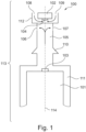
- FIG. 1 a cross-sectional schematic view of an acoustical assembly 100 comprising a receiver unit 101, a nozzle 113 comprising three portions 105, 111, 112 and a microphone unit 102 is depicted.
- the receiver unit 101 comprises a sound outlet opening 103 through which opening 103 sound pressure waves escape the receiver unit 101.
- the receiver unit 101 is adapted to generate sound within the audible range in response to a provided drive signal.
- the microphone unit 102 comprises a sound inlet opening 104 through which opening 104 incoming sound pressure waves enter the microphone unit 102.
- the microphone unit 102 provides an electrical output signal in response to detected sound pressure waves.
- the receiver unit 101 and the microphone unit 102 are arranged in line with each other, i.e. along the imaginary longitudinal centre line 114.
- the nozzle (or spout) 113 comprises three portions - a first portion 111 comprising a receiver unit mount for housing at least part of the receiver unit 101, a second portion 112 comprising a microphone unit mount for housing at least part of the microphone unit 102 and a third portion 105 connecting the first and second nozzle portions 111, 112.
- the third nozzle portion 105 comprises at least one sound channel adapted to guide generated sound pressure waves from the sound outlet opening 103 of the receiver unit 101 to at least one sound outlet opening 106, 107 of the nozzle 113 as indicated by the arrows. Possible implementations of the at least one sound channel within the third nozzle portion 105 will be discussed in further details in relation to Figs. 4 and 5 .
- the three nozzle portions 105, 111, 112 are preferably manufactured as a one-piece structure, such as a moulded one-piece structure.
- the second nozzle portion 112 comprises a microphone unit mount in the form of an indentation into which a least part of the microphone unit 102 is arranged.
- the sound inlet opening 104 of the microphone unit 102 faces, or is oriented towards, the interior of the nozzle 113 in order to prevent that ear wax, moisture or other undesired objects block or damage the microphone unit 102.
- Incoming sound pressure waves thus enter the sound channels 108, 109 (free space regions) between the microphone unit 102 and the indentation before reaching the sound inlet opening 104 as indicated by the two arrows.
- Electrical signals to and from the microphone unit 102 are provided via electrical wires through the third nozzle portion 105.
- Retaining members 110 may optionally be arranged on an exterior surface of the third nozzle portion 105. Such retaining members 110 may be used for securing a positioning member (not shown), such as a dome, to the third nozzle portion 105.
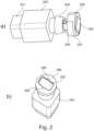
- Figs. 2a and 2b two three-dimensional views of an acoustical assembly according to the present invention are depicted.
- the receiver unit 201 is inserted into the first portion 203 of the nozzle, whereas the second portion 207 of the nozzle houses the microphone unit 202.
- A, preferably replaceable, wax protection member 206 is secured to the second portion 207 of the nozzle.
- the wax protection member 206 is adapted to secure the microphone unit 202 to the second portion 207 of the nozzle, and protect the microphone unit 202 against ear wax.
- the wax protection member 206 comprises sound inlet openings 208, 209 which are aligned with respective sound channels (not shown) of the second portion 207 of the nozzle in order to guide incoming sound pressure waves to a sound inlet opening (not shown) of the microphone unit 202.
- the nozzle further comprises a retaining member 204 and oppositely arranged sound outlet openings 205 (only one opening is visible) for the receiver unit 201.
- the oppositely arranged sound outlet openings 205 are acoustically connected to the sound outlet opening (not shown) of the receiver unit 201 via at least one sound channel within the nozzle.
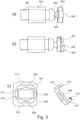
- FIG. 3b two side views of the acoustical assembly of Figs. 2a and 2b are depicted.
- the acoustical assembly is rotated 90 degrees around a longitudinal axis compared to Fig. 3a .
- the receiver unit 301 is inserted into the first portion 303 of the nozzle, said nozzle further comprising a retaining member 304, oppositely arranged sound outlet openings 305 (only one opening is visible in Fig. 3a ) and a second portion 307 for housing the microphone unit 302.
- a preferably replaceable wax protection member 306 is secured to the second portion 307 of the nozzle.
- FIG. 3c shows a top view of the acoustical assembly without the wax protection member 306.
- the microphone unit 302 is arranged at least partly in an indentation 316 provided in the second portion 307 of the nozzle.
- a small gap 317 of free space is provided between the microphone unit 302 and the edges of the indentation 316.
- sound channels 308, 309 are provided on both sides of the microphone unit 302 in order to guide incoming sound pressure waves to a sound inlet opening (not shown) of the microphone unit 302.
- the sound channels 308, 309 are aligned with sound inlet openings 208, 209 of the wax protection member 206, cf. Fig. 2b .
- a pair of oppositely arranged tracks 310, 311 are provided in the second portion 307 of the nozzle. These tracks 310, 311 are adapted to receive respective resilient leg portions 312, 313 of the wax protection member 306. Respective locking arrangements 314, 315 are provided at the ends of the legs portions 312, 313. These locking arrangements 314, 315 are adapted to engage with corresponding locking arrangements (not shown) provided at the ends of the tracks 310, 311 whereby the wax protection member 306 clicks onto the second portion 307 of the nozzle.
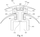
- Fig. 4 depicts a cross-sectional schematic view of an exemplary embodiment 400 of the acoustical assembly of the present invention.
- this embodiment comprises an in line arrangement of a receiver unit 401, a nozzle 403, 404 having two oppositely arranged sound outlet openings 405, 406 and a microphone unit 402. Sound pressure waves escaping the sound outlet opening 412 of the receiver unit 401 are guided to the two oppositely arranged sound outlet openings 405, 406 via respective sound channels 407, 408 within the nozzle as indicated by the two arrows.
- the microphone unit 402 is at least partly arranged in an indentation 414 in the nozzle portion 404 with its sound inlet opening 413 facing the interior of the nozzle in order to prevent that ear wax, moisture or other undesired objects block the sound inlet opening 413 of the microphone unit 402 or damages the microphone unit 402.
- incoming sound pressure waves are allowed to reach the sound inlet opening 413 of the microphone unit 402 via a gap between the microphone unit 402 and the indentation 414.
- the embodiment depicted in Fig. 4 further comprises a preferably soft and/or flexible dome-shaped positioning member 410 for positioning the acoustical assembly correctly in the ear canal.
- the positioning member 410 is preferably manufactured of a soft and flexible material, such as silicone, in order to increase comfort for the user while wearing the acoustical assembly. Moreover, a deflection member 411 comprising a sound inlet opening 409 for the microphone unit 402 is provided. As depicted in Fig. 4 the sound inlet opening 409 for the microphone unit 402 is arranged on top of the deflection member 411 thus facing the ear drum when inserted in an ear canal.
- the deflection member 411 and the positioning member 410 preferably form an integral one-piece moulded structure with sound outlet openings aligned with the corresponding sound outlet openings 405, 406 of the nozzle.
- Fig. 5 depicts a cross-sectional schematic view of another exemplary embodiment 500 of the acoustical assembly of the present invention. Similar to the embodiment of Fig. 4 this embodiment also comprises an in line arrangement of a receiver unit 501, a nozzle 503, 504 and a microphone unit 502. In contrast to the embodiment of Fig. 4 the embodiment of Fig. 5 comprises only a single sound outlet opening 505. Again, sound pressure waves escaping the sound outlet opening 510 of the receiver unit 501 are guided to the sound outlet opening 505 via a sound channel 506 within the nozzle as indicated by the arrow.
- the microphone unit 502 is at least partly arranged in an indentation 512 in the nozzle portion 504 with its sound inlet opening 511 facing the interior of the nozzle in order to prevent that ear wax, moisture or other undesired objects block the sound inlet opening 511 of the microphone unit 502 or damages the microphone unit 502.
- incoming sound pressure waves are allowed to reach the sound inlet opening 511 of the microphone unit 502 via a passage in or beneath the deflection member 509 and a gap between the microphone unit 502 and the indentation 512. Similar to the embodiment shown in Fig. 4 the embodiment depicted in Fig.
- the 5 also comprises a preferably soft and flexible dome-shaped positioning member 508 for positioning the acoustical assembly correctly in the ear canal.
- the positioning member 508 is preferably manufactured of a flexible material, such as silicone, thus increasing the comfort for the user during use.
- a deflection member 509 is also provided. As depicted in Fig. 5 a sound inlet opening 507 for the microphone unit 502 is provided in or beneath the deflection member 509 as indicated by the arrow.
- the deflection member 509 and the positioning member 508 preferably form an integral one-piece moulded structure with a sound outlet opening aligned with the opening 505 of the nozzle.
- the acoustical assembly of the present invention preferably forms part of a hearing device, i.e. hearing aids/hearables earbuds and the like, to be inserted into the ear canal of the user.
- the overall dimensions and shape of the acoustical assembly are thus limited in order to comply with such space limited applications.
Landscapes
- Engineering & Computer Science (AREA)
- Physics & Mathematics (AREA)
- Acoustics & Sound (AREA)
- Signal Processing (AREA)
- Health & Medical Sciences (AREA)
- Otolaryngology (AREA)
- Manufacturing & Machinery (AREA)
- General Health & Medical Sciences (AREA)
- Neurosurgery (AREA)
- Soundproofing, Sound Blocking, And Sound Damping (AREA)
- Headphones And Earphones (AREA)
Claims (15)
- Akustikanordnung (100), die dazu ausgelegt ist, in einen Gehörgang eingesetzt zu werden, wobei die Akustikanordnung (100) umfasst:- eine Schallerzeugereinheit (101), die dazu ausgelegt ist, Schalldruckwellen zu erzeugen,- eine Mikrofoneinheit (102), die dazu ausgelegt ist, Schalldruckwellen im Inneren des Gehörgangs zu erfassen, wenn die Akustikanordnung (100) in dem Gehörgang eingesetzt ist, und- eine Düse (113), die eine Schallerzeugereinheithalterung (111) umfasst, die dazu ausgelegt ist, mindestens einen Teil der Schallerzeugereinheit (101) aufzunehmen, wobei die Düse (113) mindestens einen Schallkanal umfasst, der dazu ausgelegt ist, erzeugte Schalldruckwellen aus einer Schallerzeugereinheit-Austrittsöffnung (103) zu mindestens einer Schallaustrittsöffnung (106, 107) der Düse (113) zu führen,wobei die Düse (113) ferner eine Mikrofoneinheithalterung (112) umfasst, die dazu ausgelegt ist, mindestens einen Teil der Mikrofoneinheit (102) aufzunehmen, dadurch gekennzeichnet,dass die Mikrofoneinheit (102) derart in der Mikrofoneinheithalterung (112) angeordnet ist, dass eine Schalleintrittsöffnung (104) der Mikrofoneinheit (102) nicht in Richtung der Ohrtrommel ausgerichtet ist, wenn die Akustikanordnung in dem Gehörgang eingesetzt ist.
- Akustikanordnung nach Anspruch 1, dadurch gekennzeichnet, dass die Mikrofoneinheit (102) derart in der Mikrofoneinheithalterung (112) angeordnet ist, dass eine Schalleintrittsöffnung (104) der Mikrofoneinheit (102) in Richtung eines Innenabschnitts der Mikrofoneinheithalterung (112) der Düse (113) ausgerichtet ist.
- Akustikanordnung nach Anspruch 1 oder 2, dadurch gekennzeichnet, dass die Düse (113) eine Längsmittelachse (114) definiert und die Schallerzeugereinheit (101) und die Mikrofoneinheit (102) symmetrisch um die Längsmittelachse (114) und in einer Linie damit angeordnet sind.
- Akustikanordnung nach einem der vorhergehenden Ansprüche, dadurch gekennzeichnet, dass die Mikrofoneinheithalterung (112) der Düse (113) eine Vertiefung umfasst, wobei die Mikrofoneinheit (102) mindestens teilweise in der Vertiefung angeordnet ist.
- Akustikanordnung nach einem der vorhergehenden Ansprüche, dadurch gekennzeichnet, dass die Mikrofoneinheithalterung (112) mindestens einen Schallkanal (108, 109) umfasst, der dazu ausgelegt ist, Schalldruckwellen aus dem Gehörgang zu der Schalleintrittsöffnung (104) der Mikrofoneinheit (102) zu führen.
- Akustikanordnung nach einem der vorhergehenden Ansprüche, dadurch gekennzeichnet, dass die Anordnung ferner ein Schmalzschutzelement (306) umfasst, das dazu ausgelegt ist, an der Mikrofoneinheithalterung (307) der Düse befestigt zu werden, wobei das Schmalzschutzelement (306) ferner dazu ausgelegt ist, zu verhindern, dass Ohrenschmalz aus dem Gehörgang die Schalleintrittsöffnung der Mikrofoneinheit (302) erreicht.
- Akustikanordnung nach Anspruch 6, dadurch gekennzeichnet, dass das Schmalzschutzelement (306) mindestens eine Schalleintrittsöffnung (208, 209) umfasst, die dazu ausgelegt ist, mit dem mindestens einen Schallkanal der Mikrofoneinheithalterung (308, 309) fluchtend ausgerichtet zu sein.
- Akustikanordnung nach einem der vorhergehenden Ansprüche, dadurch gekennzeichnet, dass die mindestens eine Schallaustrittsöffnung der Düse (106, 107) zwischen der Schallerzeugereinheithalterung (111) und der Mikrofoneinheithalterung (112) angeordnet ist.
- Akustikanordnung nach Anspruch 8, dadurch gekennzeichnet, dass eine einzelne Schallaustrittsöffnung (505) der Düse zwischen der Schallerzeugereinheithalterung und der Mikrofoneinheithalterung angeordnet ist oder dass ein Paar gegenüberliegend angeordneter Schallaustrittsöffnungen (106, 107, 405, 406) der Düse zwischen der Schallerzeugereinheithalterung und der Mikrofoneinheithalterung angeordnet ist.
- Akustikanordnung nach einem der vorhergehenden Ansprüche, dadurch gekennzeichnet, dass die Anordnung ferner ein kuppelförmiges Positionierelement (410, 508) umfasst, das dazu ausgelegt ist, eine korrekte Positionierung der Akustikanordnung in dem Gehörgang sicherzustellen, wobei das kuppelförmige Positionierelement (410, 508) an der Düse zwischen der Schallerzeugereinheithalterung (403, 503) und der Mikrofoneinheithalterung (404, 504) befestigt ist.
- Akustikanordnung nach Anspruch 10, dadurch gekennzeichnet, dass die Anordnung ferner ein Ablenkelement (411, 509) umfasst, das die Mikrofoneinheithalterung (404, 504) mindestens teilweise umgibt.
- Akustikanordnung nach Anspruch 11, dadurch gekennzeichnet, dass das kuppelförmige Positionierelement (410, 508) und das Ablenkelement (411, 509) eine einstückige Struktur aus dem gleichen Material bilden.
- Akustikanordnung nach Anspruch 12, dadurch gekennzeichnet, dass die einstückige Struktur mindestens eine Schallaustrittsöffnung umfasst, die mit der mindestens einen Schallaustrittsöffnung (405, 406, 505) der Düse fluchtend ausgerichtet ist, und dass die einstückige Struktur mindestens eine Schalleintrittsöffnung (409, 507) für die Mikrofoneinheit (102) umfasst.
- Akustikanordnung nach Anspruch 13, dadurch gekennzeichnet, dass die mindestens eine Schalleintrittsöffnung (409) für die Mikrofoneinheit (402) durch das Ablenkelement (411) angeordnet ist oder dass die mindestens eine Schalleintrittsöffnung (507) für die Mikrofoneinheit (502) zwischen dem Positionierelement (508) und dem Ablenkelement (509) angeordnet ist.
- Hörgerät, das eine Akustikanordnung nach einem der vorhergehenden Ansprüche umfasst.
Applications Claiming Priority (2)
| Application Number | Priority Date | Filing Date | Title |
|---|---|---|---|
| DKPA202070553 | 2020-08-26 | ||
| PCT/EP2021/070285 WO2022042951A1 (en) | 2020-08-26 | 2021-07-20 | Microphone unit arranged on top of receiver unit nozzle |
Publications (2)
| Publication Number | Publication Date |
|---|---|
| EP4205407A1 EP4205407A1 (de) | 2023-07-05 |
| EP4205407B1 true EP4205407B1 (de) | 2024-09-11 |
Family
ID=80354653
Family Applications (1)
| Application Number | Title | Priority Date | Filing Date |
|---|---|---|---|
| EP21748557.2A Active EP4205407B1 (de) | 2020-08-26 | 2021-07-20 | Mikrofoneinheit, die auf der düse der empfangseinheit angeordnet ist |
Country Status (5)
| Country | Link |
|---|---|
| US (1) | US20230300514A1 (de) |
| EP (1) | EP4205407B1 (de) |
| CN (1) | CN115943642A (de) |
| DK (1) | DK4205407T3 (de) |
| WO (1) | WO2022042951A1 (de) |
Citations (1)
| Publication number | Priority date | Publication date | Assignee | Title |
|---|---|---|---|---|
| CN2435886Y (zh) * | 2000-07-17 | 2001-06-20 | 许宝霞 | 移动电话用耳膜振动式免持听筒 |
Family Cites Families (6)
| Publication number | Priority date | Publication date | Assignee | Title |
|---|---|---|---|---|
| US8027481B2 (en) * | 2006-11-06 | 2011-09-27 | Terry Beard | Personal hearing control system and method |
| US7995782B2 (en) * | 2007-01-29 | 2011-08-09 | Siemens Hearing Instruments, Inc. | Combined receiver and ear-canal microphone assembly for a hearing instrument |
| CN104041077B (zh) * | 2011-12-23 | 2017-05-24 | 索诺瓦公司 | 具有梢板组件的听力装置以及制造这样的听力装置的方法 |
| EP2819435A1 (de) * | 2013-06-26 | 2014-12-31 | Oticon A/s | Belüftete Kuppel |
| US9762991B2 (en) * | 2015-08-10 | 2017-09-12 | Cotron Corporation | Passive noise-cancellation of an in-ear headset module |
| EP3367703B1 (de) * | 2017-02-27 | 2020-05-13 | Oticon A/s | Hörgerät mit einer mikrofonstruktur |
-
2021
- 2021-07-20 US US18/042,271 patent/US20230300514A1/en active Pending
- 2021-07-20 EP EP21748557.2A patent/EP4205407B1/de active Active
- 2021-07-20 WO PCT/EP2021/070285 patent/WO2022042951A1/en active Search and Examination
- 2021-07-20 CN CN202180052426.XA patent/CN115943642A/zh active Pending
- 2021-07-20 DK DK21748557.2T patent/DK4205407T3/da active
Patent Citations (1)
| Publication number | Priority date | Publication date | Assignee | Title |
|---|---|---|---|---|
| CN2435886Y (zh) * | 2000-07-17 | 2001-06-20 | 许宝霞 | 移动电话用耳膜振动式免持听筒 |
Also Published As
| Publication number | Publication date |
|---|---|
| WO2022042951A1 (en) | 2022-03-03 |
| EP4205407A1 (de) | 2023-07-05 |
| CN115943642A (zh) | 2023-04-07 |
| DK4205407T3 (da) | 2024-09-30 |
| US20230300514A1 (en) | 2023-09-21 |
Similar Documents
| Publication | Publication Date | Title |
|---|---|---|
| CN107950034B (zh) | 入耳式耳机的降噪 | |
| US9473845B2 (en) | Active noise cancelling ear phone system | |
| ES2795286T3 (es) | Estuche a prueba de agua | |
| US10375491B2 (en) | Hearing device with a barrier element | |
| EP3637799B1 (de) | Hörgerät mit gehäuse mit einem entlüftungskanal | |
| CN112913256B (zh) | 双层麦克风保护 | |
| CN109792571B (zh) | 用于噪声消除耳机的反馈麦克风适配器 | |
| DK3101918T3 (da) | Høreapparat | |
| CN211744683U (zh) | 包括dsf通道的入耳式耳机 | |
| JP2011155331A (ja) | ヘッドホンユニット | |
| EP4205407B1 (de) | Mikrofoneinheit, die auf der düse der empfangseinheit angeordnet ist | |
| KR20170134703A (ko) | 헤드폰 또는 이어폰 | |
| US11330382B2 (en) | Acoustical protector for audio devices and audio device provided with said protector | |
| KR100633050B1 (ko) | 이어폰 | |
| JP5019525B2 (ja) | 聴力保護具 | |
| US10873818B2 (en) | Damping device for a receiver of a hearing instrument and hearing instrument having such a damping device | |
| WO2006137665A1 (en) | Micro speaker unit | |
| US20240334107A1 (en) | Hearing device | |
| EP3413586B1 (de) | Okklusionskontrollsystem für ein hörgerät sowie ein hörgerät | |
| WO2007135740A1 (ja) | 電気機械音響変換器の実装構造 | |
| JP2009010565A (ja) | 発音体および電子機器 |
Legal Events
| Date | Code | Title | Description |
|---|---|---|---|
| STAA | Information on the status of an ep patent application or granted ep patent |
Free format text: STATUS: UNKNOWN |
|
| STAA | Information on the status of an ep patent application or granted ep patent |
Free format text: STATUS: THE INTERNATIONAL PUBLICATION HAS BEEN MADE |
|
| PUAI | Public reference made under article 153(3) epc to a published international application that has entered the european phase |
Free format text: ORIGINAL CODE: 0009012 |
|
| STAA | Information on the status of an ep patent application or granted ep patent |
Free format text: STATUS: REQUEST FOR EXAMINATION WAS MADE |
|
| 17P | Request for examination filed |
Effective date: 20230327 |
|
| AK | Designated contracting states |
Kind code of ref document: A1 Designated state(s): AL AT BE BG CH CY CZ DE DK EE ES FI FR GB GR HR HU IE IS IT LI LT LU LV MC MK MT NL NO PL PT RO RS SE SI SK SM TR |
|
| DAV | Request for validation of the european patent (deleted) | ||
| DAX | Request for extension of the european patent (deleted) | ||
| GRAP | Despatch of communication of intention to grant a patent |
Free format text: ORIGINAL CODE: EPIDOSNIGR1 |
|
| STAA | Information on the status of an ep patent application or granted ep patent |
Free format text: STATUS: GRANT OF PATENT IS INTENDED |
|
| INTG | Intention to grant announced |
Effective date: 20240404 |
|
| GRAS | Grant fee paid |
Free format text: ORIGINAL CODE: EPIDOSNIGR3 |
|
| GRAA | (expected) grant |
Free format text: ORIGINAL CODE: 0009210 |
|
| STAA | Information on the status of an ep patent application or granted ep patent |
Free format text: STATUS: THE PATENT HAS BEEN GRANTED |
|
| AK | Designated contracting states |
Kind code of ref document: B1 Designated state(s): AL AT BE BG CH CY CZ DE DK EE ES FI FR GB GR HR HU IE IS IT LI LT LU LV MC MK MT NL NO PL PT RO RS SE SI SK SM TR |
|
| REG | Reference to a national code |
Ref country code: GB Ref legal event code: FG4D |
|
| REG | Reference to a national code |
Ref country code: CH Ref legal event code: EP |
|
| REG | Reference to a national code |
Ref country code: DE Ref legal event code: R096 Ref document number: 602021018704 Country of ref document: DE |
|
| REG | Reference to a national code |
Ref country code: DK Ref legal event code: T3 Effective date: 20240926 |