EP4205103B1 - Verfahren zur erzeugung eines nachhallaudiosignals - Google Patents
Verfahren zur erzeugung eines nachhallaudiosignals Download PDFInfo
- Publication number
- EP4205103B1 EP4205103B1 EP21759422.5A EP21759422A EP4205103B1 EP 4205103 B1 EP4205103 B1 EP 4205103B1 EP 21759422 A EP21759422 A EP 21759422A EP 4205103 B1 EP4205103 B1 EP 4205103B1
- Authority
- EP
- European Patent Office
- Prior art keywords
- audio signal
- virtual
- distance
- determining
- symmetry group
- Prior art date
- Legal status (The legal status is an assumption and is not a legal conclusion. Google has not performed a legal analysis and makes no representation as to the accuracy of the status listed.)
- Active
Links
Images


Classifications
-
- G—PHYSICS
- G10—MUSICAL INSTRUMENTS; ACOUSTICS
- G10K—SOUND-PRODUCING DEVICES; METHODS OR DEVICES FOR PROTECTING AGAINST, OR FOR DAMPING, NOISE OR OTHER ACOUSTIC WAVES IN GENERAL; ACOUSTICS NOT OTHERWISE PROVIDED FOR
- G10K15/00—Acoustics not otherwise provided for
- G10K15/08—Arrangements for producing a reverberation or echo sound
-
- H—ELECTRICITY
- H04—ELECTRIC COMMUNICATION TECHNIQUE
- H04S—STEREOPHONIC SYSTEMS
- H04S7/00—Indicating arrangements; Control arrangements, e.g. balance control
- H04S7/30—Control circuits for electronic adaptation of the sound field
- H04S7/302—Electronic adaptation of stereophonic sound system to listener position or orientation
-
- H—ELECTRICITY
- H04—ELECTRIC COMMUNICATION TECHNIQUE
- H04S—STEREOPHONIC SYSTEMS
- H04S7/00—Indicating arrangements; Control arrangements, e.g. balance control
- H04S7/30—Control circuits for electronic adaptation of the sound field
- H04S7/305—Electronic adaptation of stereophonic audio signals to reverberation of the listening space
-
- H—ELECTRICITY
- H04—ELECTRIC COMMUNICATION TECHNIQUE
- H04S—STEREOPHONIC SYSTEMS
- H04S7/00—Indicating arrangements; Control arrangements, e.g. balance control
- H04S7/30—Control circuits for electronic adaptation of the sound field
- H04S7/307—Frequency adjustment, e.g. tone control
-
- G—PHYSICS
- G10—MUSICAL INSTRUMENTS; ACOUSTICS
- G10K—SOUND-PRODUCING DEVICES; METHODS OR DEVICES FOR PROTECTING AGAINST, OR FOR DAMPING, NOISE OR OTHER ACOUSTIC WAVES IN GENERAL; ACOUSTICS NOT OTHERWISE PROVIDED FOR
- G10K11/00—Methods or devices for transmitting, conducting or directing sound in general; Methods or devices for protecting against, or for damping, noise or other acoustic waves in general
- G10K11/002—Devices for damping, suppressing, obstructing or conducting sound in acoustic devices
-
- H—ELECTRICITY
- H04—ELECTRIC COMMUNICATION TECHNIQUE
- H04S—STEREOPHONIC SYSTEMS
- H04S2400/00—Details of stereophonic systems covered by H04S but not provided for in its groups
- H04S2400/11—Positioning of individual sound objects, e.g. moving airplane, within a sound field
-
- H—ELECTRICITY
- H04—ELECTRIC COMMUNICATION TECHNIQUE
- H04S—STEREOPHONIC SYSTEMS
- H04S7/00—Indicating arrangements; Control arrangements, e.g. balance control
- H04S7/30—Control circuits for electronic adaptation of the sound field
- H04S7/305—Electronic adaptation of stereophonic audio signals to reverberation of the listening space
- H04S7/306—For headphones
Definitions
- This disclosure relates systems and methods for generating a reverberation audio signal.
- each sound ray arriving at the listening point via one or more reflections can be simulated using a delay-line and some scale factor or filter. More generally, a tapped delay line can simulate many reflections.
- Each tap brings out one echo at an appropriate delay and gain, and each tap can be independently filtered to simulate air absorption and reflections loss.
- tapped delay lines can accurately simulate any reverberant environment, because reverberation really does consist of many paths of acoustic propagation from each source to each listening point (Smith, 1993).
- each echo can be perceived as coming from a particular angle of arrival in a 3-dimensional space.
- At least some reverberation reflections should be spatialized, i.e. distributed across spatially configured loudspeaker channels or filtered taking the head-related transfer function (HRTF) of the ear's pinnae into account e.g., so that the reflections appear to come from their natural directions (Kendall, Martens, 1984).
- HRTF head-related transfer function
- the spatialization should also change if anything changes in the listening space, including source or listener position.
- a typical reverberation time is in the order of one second.
- each filter would require 50000 multiplies and additions per sample, or 2.5 billion multiply-adds per second.
- This computational load would require at least 10 Pentium CPUs clocked at 3 Ghz, assuming the CPU would be doing nothing else at the same time, and assuming both a multiply and addition can be initiated each clock cycle, with no wait-states caused by the required memory accesses (Smith, 1993).
- the reverberation problem can be simplified without sacrificing perceptual quality.
- the echo density increases as t 2 , where t is time. Therefore, beyond some time, the amount of echoes is so great that it can be modeled as a uniformly sampled stochastic process without loss of perceptual fidelity.
- an appropriate random process sampled at the audio sampling rate will sound equivalent perceptually.
- the required time density considered perceptually acceptable is 1000 echoes per second (Schroeder, 1961). However, the time density may have to be as high as 10000 for impulsive sounds with high transients (Gardner, 1998).
- the number of resonant modes in any given frequency band increases as f 2 , so that above some frequency, the modes are so dense that they are perceptually equivalent to a random frequency response generated according to some statistics.
- the required modal density equals a regular spaced density of frequencies across the frequency range, but not too regular, since this produces audible periodicity in the time-domain and disbalances the smoothness of the response.
- the set criteria come somewhat close to exponentially decaying a white noise signal as a reverberation impulse response. This satisfies both smoothness criteria in the time domain and frequency domain (Moorer, 1979). However, since natural reverberation decays faster at high frequencies, it is better to say that the ideal reverberation impulse response is exponentially decaying 'colored' noise, with the high-frequency energy decaying faster than the low-frequency energy.
- the methods known-in-the-art for reproducing reverberation can be divided into two directions.
- artificial reverberation typically consisting of elements that constitute delay lines, comb filters and all-pass filters, an approach introduced as the Schroeder all-pass section (Schroeder, 1961) and serving as the basis for most commercial devices for artificial reverberation and related effects until today.
- stereo loudspeaker configurations or headphone virtualisation through binaural audio rendering techniques although some applications also address adaptation of the proposed methods for multi-channel distribution, typically by a particular spreading algorithm of a stereo signal across multiple channels, such as described in US2008/273708 'Early Reflection Method for Enhanced Externalisation' (Sandgren et al, 2008 ).
- every reverberation system based on such design has its own 'abstract' character, which is not representative of a specific acoustical space or situation, such as a space with a shape, size and built of particular materials; and only a limited set of parameters can be varied to modify the given character, such as the decay time, amount of damping and pre-delay being the typical front-end user variables.
- the recorded data constitute a specific and fixed set of data of one space which is not adaptable.
- transformation of such a virtual spatial model by changing or adapting its size, shape or other attributes (in real-time), is not possible.
- This gives the convolution-based approach a large disadvantage over systems based on artificial reverberation, which features are to a larger extend adaptable by a user, at least with regards to its decay time and aspect of frequency response such as damping; and, the generated audio output is more easily adaptable to provide reproduction for a variety of output systems, i.e. loudspeaker configurations.
- document US2017/238119 A1 discloses an apparatus for generating a first multitude of output signals based on at least one audio source signal having a delay network and a feedback processor.
- the delay network includes a second multitude of delay paths, each delay path having a delay line and an attenuation filter.
- Each delay line is configured for delaying delay line input signals and for combining the at least one audio source signal and a reverberated audio signal to obtain a combined signal, wherein the attenuation filter of a delay path is configured for filtering the combined signal from the delay line of the delay path to obtain an output signal.
- the first multitude of output signals includes the output signal.
- the feedback processor is configured for reverberating the first multitude of output signals to obtain a third multitude of the reverberated audio signals including the reverberated audio signal.
- a method for generating a reverberation audio signal associated with a virtual object comprises storing a representation of the virtual object, the representation defining a plurality of virtual points constituting the virtual object, wherein the virtual points have respective virtual positions with respect to each other, and wherein the virtual points belong to symmetry groups of virtual points.
- the symmetry groups of virtual points are obtainable by
- the method further comprises receiving and/or storing and/or generating an input audio signal, and, for each virtual point, determining, based on the input audio signal, or filtered version thereof, a virtual point audio signal component.
- the method also comprises combining the virtual point audio signal components to obtain a composite audio signal, and determining for each distinct distance in the further set of one or more distances, based on the composite audio signal one or more distance audio signals.
- the method also comprises determining the reverberation audio signal based on the one or more distance audio signals and the virtual point audio signal components.
- the generated reverberation audio signal possesses the same characteristics as an audio signal that has been recorded in a particular room with its particular acoustics, while actually, an virtual object as represented by the virtual points is causing the reverberation.
- the virtual object may be a virtual room having virtual walls, floor and ceiling, wherein the virtual walls, floor and ceiling consist of a certain material. In such case, a subject hearing the reverberation audio signal may perceive the audio signal as if he or she is actually standing in the virtual room.
- the center point may be understood to be a point through which a rotational axis can be defined in such manner that the virtual object can rotate, starting from an initial orientation and position, less than 360 degrees around the rotational axis and arrive at an orientation and position that are identical to the initial orientation and position.
- Such rotation of a virtual object may also be referred to as an object preserving rotation. If the virtual object for example is a square plane, then the rotational axis is perpendicular to the plane and the center point would be the midpoint of the rectangle, because a rotation of 90 degrees, which is less than 360 degrees, around such rotational axis through the midpoint would cause the square virtual object to be in a position and have an orientation that is identical to the initial position and orientation.
- Any first and second virtual point of a virtual object that are positioned symmetrically about the center point of the virtual object may be understood such that the first virtual point is at the position of the second virtual point if an object preserving rotation is performed.
- any first and second virtual point of a virtual object that are positioned at equal distances from the center point may be understood to be symmetrically positioned about the center point.
- combining two or more signals may comprise summing these signals.
- the method comprises determining for each symmetry group, based on the determined distance audio signals, one or more symmetry group audio signals. This embodiment also comprises determining the reverberation audio signal based on the symmetry group audio signals and the virtual point audio signal components.
- each symmetry group audio signal is determined based on the distance audio signals
- the reverberation audio signal is determined based on the one or more distance audio signals as well.
- determining a virtual point audio signal component for each virtual point based on the input audio signal, or filtered version thereof comprises, for each virtual point, performing a virtual-point-specific operation on the input audio signal, or modified, e.g. filtered, inverted and/or attenuated or amplified, version thereof.
- performing the virtual point specific operation comprises performing a time delay operation introducing a time delay, wherein the introduced time delay is approximately equal to a virtual distance between the virtual point in question and a virtual sound source divided by a speed of sound.
- the virtual representation also defines the virtual positions of the virtual points with respect to a virtual sound source and/or with respect to an observer.
- the virtual distance between a virtual point of the virtual object and the virtual sound source may be defined as the virtual distance between the virtual point and a center of the virtual sound source.
- the generated reverberation audio signal may be understood to reflect an audio signal that originates from this virtual sound source.
- This embodiment is advantageous in that the shape of the virtual object can be taken into account when generating the reverberation audio signal.
- the speed of sound may be the speed of sound in a virtual medium that is defined between a virtual object, a virtual sound source and an observer.
- a virtual medium between virtual object and virtual sound source may be defined to be air at a temperature of 20 C and an average 50% humidity.
- the speed of sound should be approximately 343 m/sec, which is the speed of sound in air at a temperature of 20 C and an average 50% humidity.
- the representation of the virtual object may define the virtual medium between the virtual object and the virtual sound source.
- determining for each distinct distance in the further set of one or more distances, one or more distance audio signals comprises determining for each distinct distance in the further set of one or more distances, a first distance audio signal and a second distance audio signal.
- determining the first distance audio signal for a distinct distance comprises modifying the composite audio signal by performing a time delay operation introducing a time delay and a signal feedback operation.
- determining the second distance audio signal for the distinct distance comprises modifying the composite audio signal by performing a second time delay operation introducing a second time delay and a second signal feedback operation and a signal inverting operation.
- the first distance audio signal and the second distance audio signal only differ in that one is an inverted version of the other.
- This embodiment is advantageous in that it increases the number of harmonics per distinct distance, which increases the modal density in the reverberation audio signal, and that the harmonics per distinct distance are optimally spread, i.e. odd and even harmonics are distributed to symmetrically opposite virtual points constituting the virtual object, as explained with reference to figure 11 .
- the first time delay introduced by the first time delay operation is equal to the distinct distance divided by a speed of sound.
- the speed of sound is preferably the speed sound associated with the virtual medium between the virtual object and virtual sound source as for example defined by the representation of the virtual object.
- the selection of the signals to be used for determining the first symmetry group audio signal may be performed in an arbitrary manner. This embodiment ensures that out of each pair of first and second distance audio signal one contributes to the first symmetry group audio signal and the other contributes to the second symmetry group audio signal.
- determining the audio signal based on the symmetry group audio signals and the virtual point audio signal components comprises combining the symmetry group audio signals with the virtual point audio signal components to determine said reverberation audio signal.
- a reverberation audio signal preferably mimics the first reflections from the virtual object as well as the reverberation tail that the virtual object produces.
- the virtual point audio signal components cause the reverberation audio signal to mimic the first reflections from the virtual object whereas the symmetry group audio signals cause the reverberation audio signal to comprise a reverberation tail associated with the virtual object.
- determining the audio signal based on the symmetry group audio signals and the virtual point audio signal components comprises combining the symmetry group audio signals with the virtual point audio signal components to determine said reverberation audio signal.
- combining the symmetry group audio signals with the virtual point audio signal components to determine said audio signal comprises determining modified audio signal components.
- determining modified audio signal components comprises adding, to each virtual point audio signal component determined for a virtual point belonging to a symmetry group, the first or second symmetry group audio signal of the symmetry group in question.
- This embodiment provides an efficient manner for combining the symmetry group audio signals with the virtual point audio signal components.
- Determining the modified audio signal components may further comprise other operations for adding resonance, depth, height and distance characteristics to the audio signal components.
- the method comprises performing the method according to any of the preceding claims for generating a further reverberation audio signal for a further virtual object, wherein the determined reverberation audio signal associated with the virtual object is used as input audio signal.
- This embodiment enables to simulate one reverberating virtual object producing a reverberation audio signal that is incident on another virtual object.
- This allows to generate reverberation audio signals for complex virtual systems comprising multiple virtual objects, such as several, differently oriented surfaces, such as walls, ceilings, floors, et cetera.
- the method further comprises combining the reverberation audio signal associated with the virtual object and the further reverberation audio signal associated with the further virtual object, and, optionally, providing the combination to one or more loudspeakers.
- the method further comprises providing the determined audio signal to one or more loudspeakers.
- the method comprises providing the modified audio signal components to one or more loudspeakers comprises providing the modified audio signal components to a panning system that is configured to distribute the modified audio signal components to a plurality of loudspeakers.
- Distributing the modified audio signal components may comprise determining a number of output audio signals, one for each loudspeaker, based on the modified audio signal components.
- the method further comprises filtering the input audio signal before determining, for each virtual point, a virtual point audio signal component.
- Filtering the input audio signal comprises applying a multi-band filter comprising attenuating respective frequency bands in the input audio signal using respective attenuation coefficients, wherein the respective attenuation coefficients are determined based on a material of the virtual object.
- the representation defining the virtual object also defines out of which material the virtual object consists.
- the representation may define that the virtual object consists of limestone.
- the material of the virtual object may have known specific absorption coefficients for respective frequency bands.
- the attenuation coefficients that are used for the multiband filters may be determined on the basis of these absorption coefficients.
- determining for each distinct distance in the further set of one or more distances, one or more distance audio signals comprises determining for each distinct distance in the further set of one or more distances, a distance audio signal. Determining such distance audio signal comprises modifying the composite audio signal by performing a time delay operation introducing a time delay, a signal attenuation operation, a low-pass filter operation and a signal feedback operation. This embodiment also comprises determining for at least one, preferably for each, symmetry group of virtual points a density index. Determining the density index for the at least one symmetry group comprises
- This embodiment also comprises receiving a threshold value for the density index, and determining that the determined density index is lower than said threshold value, and, based on this determination, changing the stored representation by increasing the number of virtual points that constitute the virtual object.
- increasing the number of virtual points which may also be referred to as increasing the resolution of virtual points, causes the amount of distinct distances comprising the further set of one or more distances to become larger; and, causes the time delays used for determining the respective distance audio signals to become smaller.
- more feedback operations are performed per unit of time.
- Each feedback operation may be understood to represent an echo.
- this embodiment may be said to ensure that sufficient echoes are generated.
- the low pass filter operation comprises
- One aspect of this disclosure relates to a computer comprising a computer readable storage medium having computer readable program code embodied therewith, and a processor, preferably a microprocessor, coupled to the computer readable storage medium, wherein responsive to executing the computer readable program code, the processor is configured to perform any of the methods described herein.
- One aspect of this disclosure relates to a computer program or suite of computer programs comprising at least one software code portion or a computer program product storing at least one software code portion, the software code portion, when run on a computer system, being configured for executing any of the methods described herein.
- One aspect of this disclosure relates to a non-transitory computer-readable storage medium storing at least one software code portion, the software code portion, when executed or processed by a computer, is configured to perform any of the methods described herein.
- aspects of the present invention may be embodied as a system, a method or a computer program product. Accordingly, aspects of the present invention may take the form of an entirely hardware embodiment, an entirely software embodiment (including firmware, resident software, micro-code, etc.) or an embodiment combining software and hardware aspects that may all generally be referred to herein as a "circuit,” “module” or “system.” Functions described in this disclosure may be implemented as an algorithm executed by a processor/microprocessor of a computer. Furthermore, aspects of the present invention may take the form of a computer program product embodied in one or more computer readable medium(s) having computer readable program code embodied, e.g., stored, thereon.
- the computer readable medium may be a computer readable signal medium or a computer readable storage medium.
- a computer readable storage medium may be, for example, but not limited to, an electronic, magnetic, optical, electromagnetic, infrared, or semiconductor system, apparatus, or device, or any suitable combination of the foregoing.
- a computer readable storage medium may include, but are not limited to, the following: an electrical connection having one or more wires, a portable computer diskette, a hard disk, a random access memory (RAM), a read-only memory (ROM), an erasable programmable read-only memory (EPROM or Flash memory), an optical fiber, a portable compact disc read-only memory (CD-ROM), an optical storage device, a magnetic storage device, or any suitable combination of the foregoing.
- a computer readable storage medium may be any tangible medium that can contain, or store, a program for use by or in connection with an instruction execution system, apparatus, or device.
- a computer readable signal medium may include a propagated data signal with computer readable program code embodied therein, for example, in baseband or as part of a carrier wave. Such a propagated signal may take any of a variety of forms, including, but not limited to, electro-magnetic, optical, or any suitable combination thereof.
- a computer readable signal medium may be any computer readable medium that is not a computer readable storage medium and that can communicate, propagate, or transport a program for use by or in connection with an instruction execution system, apparatus, or device.
- Program code embodied on a computer readable medium may be transmitted using any appropriate medium, including but not limited to wireless, wireline, optical fiber, cable, RF, etc., or any suitable combination of the foregoing.
- Computer program code for carrying out operations for aspects of the present invention may be written in any combination of one or more programming languages, including an object oriented programming language such as Java(TM), Smalltalk, C++ or the like and conventional procedural programming languages, such as the "C" programming language or similar programming languages.
- the program code may execute entirely on the user's computer, partly on the user's computer, as a stand-alone software package, partly on the user's computer and partly on a remote computer, or entirely on the remote computer or server.
- the remote computer may be connected to the user's computer through any type of network, including a local area network (LAN) or a wide area network (WAN), or the connection may be made to an external computer (for example, through the Internet using an Internet Service Provider).
- LAN local area network
- WAN wide area network
- Internet Service Provider an Internet Service Provider
- These computer program instructions may be provided to a processor, in particular a microprocessor or a central processing unit (CPU), of a general purpose computer, special purpose computer, or other programmable data processing apparatus to produce a machine, such that the instructions, which execute via the processor of the computer, other programmable data processing apparatus, or other devices create means for implementing the functions/acts specified in the flowchart and/or block diagram block or blocks.
- a processor in particular a microprocessor or a central processing unit (CPU), of a general purpose computer, special purpose computer, or other programmable data processing apparatus to produce a machine, such that the instructions, which execute via the processor of the computer, other programmable data processing apparatus, or other devices create means for implementing the functions/acts specified in the flowchart and/or block diagram block or blocks.
- These computer program instructions may also be stored in a computer readable medium that can direct a computer, other programmable data processing apparatus, or other devices to function in a particular manner, such that the instructions stored in the computer readable medium produce an article of manufacture including instructions which implement the function/act specified in the flowchart and/or block diagram block or blocks.
- the computer program instructions may also be loaded onto a computer, other programmable data processing apparatus, or other devices to cause a series of operational steps to be performed on the computer, other programmable apparatus or other devices to produce a computer implemented process such that the instructions which execute on the computer or other programmable apparatus provide processes for implementing the functions/acts specified in the flowchart and/or block diagram block or blocks.
- each block in the flowchart or block diagrams may represent a module, segment, or portion of code, which comprises one or more executable instructions for implementing the specified logical function(s).
- the functions noted in the blocks may occur out of the order noted in the figures. For example, two blocks shown in succession may, in fact, be executed substantially concurrently, or the blocks may sometimes be executed in the reverse order, depending upon the functionality involved.
- a computer program for carrying out the methods described herein, as well as a non-transitory computer readable storage-medium storing the computer program are provided.
- a computer program may, for example, be downloaded (updated) to the existing data processing systems or be stored upon manufacturing of these systems.
- This disclosure relates to methods and systems for generating a reverberation audio signal.
- An actual reverberation audio signal may be understood to be formed by sound reflections by an object and also subsequent vibrations in such object.
- the generated reverberation audio signal as described herein is associated with a virtual object in the sense that the reverberation audio signal comprises the same characteristics as an actually recorded audio signal that is subject to the reverberation of such object.
- the virtual object may have any shape, size and/or characteristics.
- the methods described herein enable to generate reverberation audio signals at the highest computational efficiency allowing real-time processing.
- the ability to generate the reverberation audio signal in real-time for example allows to change characteristics of the virtual object, such as its shape, position, orientation and/or the material out of which the virtual object is formed, and to immediately generate the reverberation audio signal associated with the changed virtual object.
- the conditions of a virtual acoustical space, such as its material construct, conditions for sound propagation, the spatial distance, height and depth of sound sources reflecting in the space and/or from objects comprising other sound sources can be changed and these changes can be quickly processed.
- the method and system for generating the reverberation audio signal uses relatively simple elements of artificial reverberation, such as delay lines and low-pass filters.
- the technologies disclosed herein are designed to minimize the number of delay lines required in the system, for example in that smart signal distribution across multiple audio components is realized, which is computationally much less expensive.
- the technologies disclosed herein enable to add features to an input audio signal such to make it seem as if the input audio signal has been generated and/or recorded in an actual acoustical space of a given shape, size and materiality.
- the method is optimally efficient and scalable in resolution for lower to high-capacity CPU requirements.
- the method allows for an interactive model for generating reverberation as the processes may be executed in real-time while performing at optimal resolution given by the conditions of the CPU used.
- the method allows adaptability to any variety of loudspeaker configurations and amounts of loudspeakers used in a configuration, stimulating new approaches to loudspeaker system design while also being backwards compatible with existing audio reproduction formats, such as mono, stereo and/or HTRF-based headphone sound reproduction.
- the method to obtain the delay times is not based on fixed sets of time delay values with a statistically valid outcome, but may be generated in real-time from a 'shape generator' operation which allows to model a shape of any type and/or character by determining a virtual point resolution, i.e. a set of points defined on the virtual shape.
- the resulting time delays are filtered using a 'value filter' operation that extrapolates essential data from the shape, such that it will accurately represent the acoustical shape in the first and early reflections of the reverberation, while at the same time producing a reverberation tail, i.e.
- the invention introduces new approaches to automate optimisation of density and sample rate requirements for different user conditions set by a user.
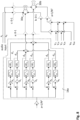
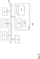
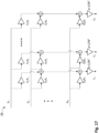
- the method for generating a reverberation audio signal involves a representation of a virtual object 2, such as a square plate depicted in figure 1 .
- the representation defines a plurality of virtual points, numbered ⁇ 1, 2, 3, ..., N ⁇ in figure 1 .
- N indicates the total number of virtual points.
- the virtual points have respective virtual positions with respect to each other and with respect to a center point 4 of the virtual object 2.
- the virtual points belong to symmetry groups of virtual points, wherein virtual points that are positioned symmetrically about the center point, belong to the same symmetry group of virtual points. This will be explained in more detail with reference to figure 9 .
- the virtual points defined by the representation also have a specific position with respect to an observer 6.
- the virtual object may for example be positioned at a certain distance from the observer, at a depth below the observer or at a height above the observer.
- the virtual points may also have a position with respect to a sound source 8.
- the observer 6 may perceive that the virtual object 2 has a shape, i.e. a distinct dimensional shape, size and materiality, and may perceive the sound source 8 and reverberating space at a distinct height, depth and distance in relation to the observer.
- Such perception closely resembles how one experiences sound in a real space of such shape, size and material construction, and how one can move through this space and explore how it sounds from any position and angle.
- a listener may virtually and/or physically move through space and experience the resulting sound reverberation, i.e. the acoustics of a space of a particular size, shape and materiality, from any position and angle inside and/or outside the reverb space, and experience the result of the excitation of the reverberation of a virtual object located at any virtual position.
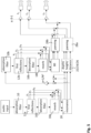
- FIG. 2 is a flow chart illustrating a method for generating a reverberation audio signal according to an embodiment.
- an input audio signal x is provided to a multi-band filter that is configured to attenuate respective frequency bands in the input audio signal using respective attenuation coefficients.
- An attenuation coefficient may be understood to define a degree of attenuation for a specific frequency band.
- the multi-band filter may be configured to attenuate a first frequency band using an attenuation coefficient of 0.7 and a second frequency band using an attenuation coefficient of 0.5.
- the intensities of frequencies in the first frequency band are damped with a factor 0.7 and the intensities of frequencies in the second frequency band are damped with a factor 0.5.
- Such filter 10 may also be referred to as an absorption filter because it may be used to model the absorption of sound by the virtual object.
- the absorption filter is an 8-octave band equalizer.
- the output of filter 10 is subsequently provided to a first reflections module 12.
- a first reflections module 12 preferably comprises a plurality of parallel signal flows, one for each virtual point of the virtual object 2 in order to determine a virtual point audio signal component y_n for each virtual point as shown.
- a module may also be referred to as a flow process, flow chart or the like.
- the composite audio signal 14 is provided to a second filter 16, which may be identical to filter 10.
- the module 18 comprises a plurality of parallel signal flows, one for each to be generated distance audio signal as described herein.
- the module 18 determines one or more distance audio signals d_k+/-, i.e. ⁇ d_1+, d_1-, d_2+, d_2-, ..., d_K+, d_K- ⁇ (not shown).
- K as used in this disclosure indicates the total number of distinct distances in the further set of one or more distances as described herein.
- the module 18 outputs a number of symmetry group audio signals s_m+/-, i.e. ⁇ s_1 +, s_1-, s_2+, s_2-, ..., s_M+, s_M- ⁇ .
- M indicates the total number of symmetry groups.
- the symmetry group audio signals s_m+/- are combined with the virtual point audio signal components y_n. This combination results in a reverberation audio signal according to an embodiment.
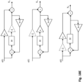
- FIG. 2 further shows optional modules, namely resonance module 20, depth module 22, height module 24, distance module 26, panning system 28. These modules are not required for generating a reverberation audio signal, but are required for coherent projection of the reverberation audio signal with respect to an observer, i.e. the reverberation is perceived at distinct depth, height and distance and angle by the observer.
- the resonance module 20 is configured to perform a spatial wave transform on audio signal components for adding resonance characteristics to the audio signal components, the sum of which may be a mix-down 21 of an audio input signal for a (second) signal process as described herein.
- the depth module 22 is configured to encode depth to audio signal components.
- the height module 24 module is configured to encode height to audio signal components.
- the distance module 26 is configured to encode distance to audio signal components.
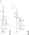
- Adding resonance characteristics may comprise (see figure 16A ) modifying the audio signal component in order to obtain a first modified audio signal component.
- This modification of the audio signal component optionally comprises a signal inverting operation 74, comprises a signal delay operation 75 introducing a time delay, and optionally comprises a signal feedback operation 73 as shown.
- the signal that is fed back is attenuated as shown by the amplifier 76 having a gain smaller than 1.
- the first modified audio signal component is combined, see the summation 78, with the audio signal component in order to obtain a second modified audio signal component.
- the second modified audio signal is further modified by an attenuation operation 79 and, optionally, a high-pass filter operation 80 to obtain an audio signal component y_n' associated with a virtual point of the virtual object.
- the determination of the audio signal components is also described in patent applications NL2024434 and NL2025950 which contents should be considered included in this disclosure in their entirety.
- the attenuation operation 79 after the summation operation 78 may comprise decreasing the gain G of the audio signal with -6 dB.
- values in the triangles i.e. in the attenuation or amplification operations, may be understood to indicate a constant with which a signal is multiplied. These constants are often indicated by “a” or "b ". Thus, if such value is larger than 1, then a signal amplification is performed. If such value is smaller than 1, then a signal attenuation is performed.
- v is a constant relating to the speed of sound through a medium
- V is the dimensional volume of a virtual shape
- r n denotes the spherical radius from the center of a virtual shape to point n
- R denotes the spherical radius from the center of the shape passing through the vertices where two or more edges of a virtual shape meet.
- the largest value R is considered.
- any of the flow charts depicted in any of the figures 18A - 18G may be used instead for adding resonance characteristics with the same parameter values.
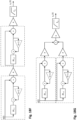
- Adding depth characteristics to an audio signal component may comprise (see figure 16B ) modifying the audio signal component y_n in question using a time delay operation 86 introducing a time delay, a signal attenuation 88 and a signal feedback operation 90 in order to obtain a modified version of the audio signal component and combining 92 the modified version of the audio signal component with the audio signal component in question.
- the signal attenuation 88 is performed in dependence of the virtual depth below the subject of the virtual point associated with the audio signal component in question.
- b preferably between 0-1, a change in depth is added to the audio signal.
- the time delay ⁇ t that is introduced by the time delay operation is as short as possible, e.g. shorter than 0.00007 seconds, preferably shorter than 0.00005 seconds, more preferably shorter than 0.00002 seconds. Most preferably, approximately 0.00001 seconds. In case of a digital sample rate of 96 kHz, the time delay may be 0.00001 seconds.
- Adding height characteristics to an audio signal component comprises (see figure 16C ) modifying the audio signal component in question using a signal inverting operation 140, a signal delay operation 142 introducing a time delay and a signal attenuation 144 to obtain a modified version of the audio signal component and combining 146 the modified version of the audio signal component with the audio signal component in question.
- the signal attenuation 144 is performed in dependence of the virtual height of the virtual sound source.
- the time delay ⁇ t that is introduced by the time delay operation 142 is as short as possible, e.g. shorter than 0.00007 seconds, preferably shorter than 0.00005 seconds, more preferably shorter than 0.00002 seconds. Most preferably, approximately 0.00001 seconds. In case of a digital sample rate of 96 kHz, the time delay may be 0.00001 seconds.
- Adding distance characteristics to an audio signal component comprises (see figure 16D ) modifying the audio signal component in question using a first signal delay operation 160 introducing a first time delay, a first signal attenuation operation 162 and a signal feedback operation 164 in order to obtain a first modified version of the audio signal component and combining 166 the first modified version of the audio signal component with the audio signal component in question to obtain a second modified version of the audio signal component and performing a second signal attenuation 168 and optionally a second signal delay operation 170 introducing a second time delay on the second modified version of the audio signal component.
- the first 162 and second 168 signal attenuation are performed in dependence of the virtual distance from the subject.
- the values for b, the attenuation constant for operation 162, and the value for a, the attenuation constant for operation 168 is varied.
- the constants may be understood to indicate a constant with which a signal is multiplied. Thus, if such value is larger than 1, then a signal amplification is performed. If such value is smaller than 1, then a signal attenuation is performed.
- the time delay ⁇ t 1 that is introduced by the time delay operation 160 is as short as possible, e.g. shorter than 0.00007 seconds, preferably shorter than 0.00005 seconds, more preferably shorter than 0.00002 seconds. Most preferably, approximately 0.00001 seconds. In case of a digital sample rate of 96 kHz, the time delay may be 0.00001 seconds
- the optional time delay ⁇ t 2 that is introduced by the time delay operation 170 creates a Doppler effect associated with movement of the virtual sound source.
- the panning module 28 is configured to attenuate and sum the modified audio signal components y'_n to generate audio output signals z_p, i.e. ⁇ z_1, z_2, z_3, ..., z_P ⁇ , each audio output signal associated with a discrete loudspeaker p.
- "P" as used herein indicates the total number of loudspeakers.
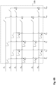
- Fig. 17 is a flow chart illustrating a method for determining a loudspeaker audio signal z_p for each loudspeaker p of a plurality P of loudspeakers.
- the depicted method and system may also be referred to as a signal distribution matrix 28 or panning matrix 28.
- a loudspeaker audio signal z_p is determined for each loudspeaker p (not shown) of a plurality of loudspeakers.
- Input to the signal distribution matrix is the plurality of audio signal components associated with respective virtual points of the virtual sound source which plurality of audio signal components y_n have been determined in accordance with methods described herein.
- Each loudspeaker p is associated with a loudspeaker coefficient a_p.
- determining loudspeaker audio signal z_p for loudspeaker p comprises attenuating each audio signal component y_n based on loudspeaker coefficient a_p in order to obtain a loudspeaker specific set of attenuated audio signal components.
- a loudspeaker coefficient for a loudspeaker may be determined based on a distance between the loudspeaker in question and the virtual point. Attenuating each audio signal component y_n based on loudspeaker coefficient a_p may involve simply a multiplication y_n * a_zp.
- the loudspeaker specific set of attenuated audio signal components for loudspeaker p may be described by : ⁇ y_1 * a_p ; y_2 * a_p ; y_3 * a_p ; ... ; y_N * a_p ⁇ , wherein N denotes the total number of virtual points defined for the virtual sound source. Subsequently, the audio signal components in this set are combined, e.g. summed, in order to arrive at the loudspeaker audio signal z_p for loudspeaker p. This method is performed for all loudspeakers P.
- the signal distribution matrix 28 may have a multiplier and a summation at each position where an input line to which an output signal of a multiplier is supplied, crosses an output, as shown in figure 17 .
- the multiplier attenuates the signal received from the input line by a prescribed loudspeaker coefficient specified by a controller, such as the values generated for each loudspeaker amplitude by f.i. a panning system commonly known-in-the-art, and outputs a resulting signal to the summation.
- the processing that the multiplier multiplies a signal by a prescribed coefficient may be referred to as a 'three-dimensional panning processing'.
- the controller may give the related coefficient proper values corresponding to the respective output systems so that the resulting audio signal that is provided to the subject by means of the plurality of loudspeakers, has a shape and a location in space, e.g. an angle, distance, depth and height in relation to the subject.
- the sound is simulated properly for the propagation of direction and dimensions from the virtual sound source to the subject.
- the summations supply audio output signals of the multipliers to the respective output lines, each associated with a loudspeaker in a loudspeaker configuration.
- Figure 3 is a flow chart illustrating the inputs for the respective modules described in figure 2 according to an embodiment.
- the method may comprise a shape generator 30 for determining the dimensions, position and orientation of the virtual object, which may also be referred to as "shape data".
- the shape generator may output the set of virtual points constituting the virtual object, each virtual point in the set of virtual points being associated with a virtual position.
- the virtual points may be input to the respective modules as shown.
- the shape generator is further described below with reference to figure 21 .
- Figure 21 illustrates a method to determine the representation defining the virtual object.
- the representation indicates the spatial dimensions of a virtual object, i.e. the shape and size and its position relative to the subject, and, optionally, the density of the virtual object.
- the virtual points may be equally distributed over the surfaces or across the volume of the virtual object. A higher density of the virtual points on such surface or across such volume corresponds to a higher resolution.
- the virtual object can be defined to be hollow.
- the representation does not define virtual points "inside” the virtual object, but only on the external surfaces and edges of the virtual object.
- the virtual object can also be “solid”.
- the representation defines, in addition to virtual points on the exterior surfaces and edges of the virtual object, virtual points "inside" the virtual object, which may be equally distributed across the interior volume of the virtual object.
- a virtual object has a geometric shape, i.e. a pure dimensional shape, or semi-geometric, irregular or may be organically shaped. It should be understood that the virtual object may have any form and that any method may be used to determine the shape of the virtual object and the virtual points constituting the shape of the virtual object.
- the density of the virtual points may also be referred to as the resolution of the virtual points and/or the 'grid resolution'.
- Figure 21 illustrates that obtaining the representation may comprise obtaining dimensions of the virtual object 210 and the virtual point positions 212.
- Obtaining the shape dimensions 210 may comprise a shape generator generating a container 214 of scalable dimensions (xyz) and determining shape coordinates 216 and a shape volume within the boundaries of the scaled dimensions to obtain the dimensions of the virtual object.
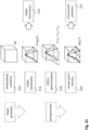
- the virtual object is shaped as a pyramid.
- obtaining the virtual point positions 212 may comprise a grid generator determining a lattice 218, where three main lattices are introduced in accordance with the dimensions of chosen shape; and, determining the virtual point density 220 by defining a resolution of points along each of the introduced lattices, to obtain the virtual point positions within a shape.
- L a . Z . v_1 + Z . v_2 + Z . v_3
- Z is the ring of integers
- the patterns of overlapping or tangent circles generated by the lattice is considered, where a sphere is centered around each virtual point of the grid.
- the radius of the circles may be increased to influence the generated patterns of the sound propagation in space.
- the method may comprise a 'sample rate interpolator' operation 32.
- This operation is preferably performed in dependence of position data (x, y, z) of the virtual input source to modify the signal process performed in first reflections module 12.
- the operation is also performed in dependence of obtained shape data and serves to modify and optimize the signal process of the reverb module 18.
- the sample rate interpolation is further described below with reference to figure 13 .
- the method for generating a reverberation audio signal may also comprise a 'value filter' operation 34, a 'time density scaler' operation 36. These operations may be performed in dependence of obtained shape data and serve to modify and optimize the signal process of the reverb module 18.
- the operations 34 and 36 are further described below with reference to figure 12 .
- the method may further comprise obtaining controller data with regards to the input source position (x, y, z) and rotation (x, y, z) and a 'vantage point' which denotes the virtual and/or actual position of the listener and applying obtained data as an input for multiple modules of the digital signal process.
- the described audio signal processing in figure 2 and the shape data acquisition and modification, sample rate interpolation, value filtering and time density scaling in figure 3 may be performed in real-time, e.g. by running a software programme or code portion.
- One aspect of this disclosure relates to a data processing system that is configured to perform the method for generating a reverberation audio signal as described herein.
- Such data processing system may be connected to an audio output port; and, optionally, to an audio input port to acquire audio input signals in real-time.
- an embodiment of the invention may include performing (part of) one, several and/or all of the modules described in figure 2 and figure 3 ; and that modules may be performed in a different order and/or may be repeatedly performed.
- Figure 4 illustrates a method for generating a reverberation audio signal according to an embodiment, wherein a further reverberation audio signal 40b is determined for a further virtual object by performing a method 42b, besides the determination of reverberation audio signal 40a by performing the method 42a. Even further reverberation audio signals may be generated, e.g. signal 40c, by performing method 42c.
- methods 42a, 42b, 42c may be methods for determining a reverberation audio signal as described herein. These methods may all for example be the method as shown in figure 2 .
- each method 42 indicated in figure 4 is associated with a combination of a virtual sound source and a virtual object.
- a signal is taken that is generated by the method 42a.
- signal 21 as indicated in figure 2 is used as input audio signal for generating a further reverberation audio signal.
- method 42b also receives as input the virtual position of the virtual object associated with method 42a, i.e. the virtual object for which method 42a generates the reverberation audio signal 40a. This namely allows to determine the virtual positions of the virtual points of the virtual object associated with method 42b with respect to the "virtual sound source", which source for method 42b is the virtual object associated with method 42a.
- an even further method 42c for determining a reverberation audio signal 40c may be performed using as input audio signal any of the signals generated while performing method 42b, preferably, the signal 21 indicated in figure 2 .
- method 42c also receives as input the position of the virtual object associated with method 42b, i.e. the virtual object for which the reverberation audio signal 40b is generated.
- any number of signals may be the input for any number of methods 42_x for determining a reverberation audio signal, e.g. in a chain and/or simultaneously.
- a method for generating a reverberation audio signal may use a combination of signals as audio input signal.
- method 42a can generate a signal that is input for a further method 42b for generating a further reverberation audio signal
- a signal generated while performing method 42b can at the same time generate a signal that is used as input audio signal for method 42a again.
- a feedback operation is enabled between methods 42a and 42b, where both objects respectively associated with these methods reflect into each other producing a reverberation in dependence of an audio input signal inserted initially in either of the methods 42a or 42b.
- each method 42a and 42b has as input its own shape data and the spatial position and rotation (x, y, z) because they are associated with different reverberation virtual objects.
- a virtual object as referred to in this disclosure may form a virtual sound source as referred to in this disclosure for a further virtual object.
- Embodiments as depicted in figure 4 thus enable to establish relationships between sound sources and virtual objects.
- a virtual object as used herein may be understood to virtually represent an object that reflects and reverberates sound from an excitation source, also referred to as "sound source” or "input source”.
- reverberation audio signal 40a and the further reverberation audio signal 40b, and optionally even further reverberation audio signals, such as signal 40c may be combined in order to determine a final reverberation signal that can be fed, optionally via a panning system, to a set of one or more loudspeakers.
- Figure 5 illustrates an embodiment, wherein an audio input signal x is used as input audio signal for a first reverberation audio signal generating method according to an embodiment and wherein the resulting reverberation audio signal is subsequently used as input audio signal for a second reverberation audio signal generating method according to an embodiment.
- Both methods generate discrete audio output signals z_p for each loudspeaker p in a loudspeaker configuration, which, before being fed to the loudspeakers are first summed and optionally attenuated and/or amplified with a multiplier ranging from 0-1.
- Figure 6 is a detailed flow chart illustrating a reverberation audio signal generating method according to an embodiment.
- This embodiment comprises receiving an input audio signal (see left hand side of figure 6 ).
- the input audio signal optionally is the sum of audio signal components that have been determined while performing another reverberation audio signal generating method according to an embodiment, as described in figure 5 .
- the embodiment of figure 6 comprises providing the input audio signal to a multi-band filter 10 (also see figure 2 ).
- this embodiment comprises filtering the input audio signal which comprises applying a multi-band filter 10.
- Applying multi-band filter 10 comprises attenuating respective frequency bands in the input audio signal using respective attenuation coefficients, wherein the respective attenuation coefficients are determined based on a material of the virtual object.
- the multi-band filter consists of an 8-octave band equalizer for which the attenuation coefficients a(dB) are determined individually for each frequency band f.
- the value for ⁇ may be obtained from the standard ISO354 for absorption coefficients, the data comprising standardized methods for material testing (Bork, 2005b).
- the virtual object is a limestone wall.
- an input audio signal is modified so that the difference of the one-sided intensity of the reflected sound (Ir ⁇ Pt) and the one-sided intensity of the incident sound (Ii ⁇ Pi) is the absorption of energy of the sound by a limestone wall.
- the resulting reverberation will thus constitute characteristics of a distinct materiality.
- the method further comprises (in first reflections module 12, also see figure 2 ) determining for each virtual point of the virtual object, based on the filtered version of the input audio signal, a virtual point audio signal component y(t)_n.
- determining each virtual point audio signal component y(t)_n comprises performing a virtual-point-specific operation on the (filtered) audio input signal.
- the virtual-point-specific operation comprises performing an attenuation operation 52 for attenuating a signal, a low-pass filter operation 54 for filtering out higher frequencies than a threshold frequency and a time delay operation 56 for introducing a time delay.
- filtering out frequencies above or below a threshold frequency may be understood to be attenuating frequencies with gradual increase up until and above, or respectively, up until and below such threshold frequencies. Filtering out thus does not mean that frequencies higher, or respectively, lower than the cut-off frequency are completely removed and/or not removed.
- the first reflections module 12 generates the first reflections of the sound.
- Each audio signal component y n is associated with a discrete virtual point of the virtual object. Further, each virtual point audio signal component y n is determined based on the virtual position of its associated virtual point, in particular based on its virtual distance from a virtual sound source.
- the generated reverberation audio signal may namely be understood to reflect an audio signal that originates from this virtual sound source.
- the position of this virtual sound source is defined, for example, in the virtual representation of the virtual object.
- the attenuation operation 52, the low-pass filtering operation 54 and the time delay operation 56 for each virtual point may be performed in any order; and that one or more steps may be omitted, repeated, modified and/or added.
- an optional multiplication factor x, a 'scaler' may be added at any other step in the described audio signal process to provide a parameter scaling function, and that this scaler may be performed by a user sending controller data to modify aspects of the sounding output of the reverberation, i.e. increasing or decreasing the output values, thus enlarging or diminishing the effects of the operation.
- the low-pass filter 54 constitutes a damping function of the audio signal component y n in dependence of the distance r between the virtual point and the virtual sound source, where the attenuation a(dB/m) of frequency f(Hz) is a function of the absorption of sound propagating through a medium, comprising the high-frequency dissipation of the sound before its reflection.
- p a is the ambient atmospheric pressure in kPa
- T is the ambient atmospheric temperature
- virtual point audio signal components y n are generated.
- the components y n resemble first reflections of sound originating from a sound source and reflected by the virtual object in dependence of the position of the virtual object with respect to the sound source.
- the components y n are also determined in accordance with conditions that influence the propagation of sound through a medium, such as the atmosphere of a certain temperature and humidity.
- the virtual point audio signal components y n also referred to as y(t)_n, resulting from the first reflections operation 12 are (i) passed as audio signal components to be summed with the symmetry group audio signals resulting from the reverb operation 18, as shown in Fig 6C ; and (ii) summed (see combiner 53) to obtain a composite audio signal.
- the composite audio signal is then filtered by performing a second multi-band filtering operation 16, which may be an absorption filter as described above.
- the values chosen for the first absorption filter 10 from the ISO354 are preferably the same values for the second absorption filter 16.
- the filtered composite audio signal is then attenuated by performing an attenuation operation 57.
- the embodiment further comprises determining the one or more distance audio signal d_k as described herein, in this example two distance audio signals per distinct distance in the further set of one or more distances, namely a first distance audio signal d_k+ and a second distance audio signal d_k-.
- determining the first distance audio signal for a distinct distance comprises modifying the composite audio signal by performing a time delay operation 64 introducing a time delay and a signal feedback operation 58. Determining the first distance audio signal also comprises performing an attenuation operation 60 and a low-pass filter operation 62.
- determining the second distance audio signal for a distinct distance comprises modifying the composite audio signal by performing a second time delay operation 72 introducing a second time delay, a signal inverting operation 68, a signal attenuation operation 68, a low pass filter operation 70 and a second signal feedback operation 66.
- operations 64 and 72 are identical
- operations 62 and 70 are identical.
- the attenuation performed by respectively operation 60 and 68 is identical, with note being taken that operation 68 inverts the signal and operation 60 does not.
- Performing a signal feedback operation may involve recursively adding the distance audio signal back to the input itself before the attenuation operation, for example as shown. It should be appreciated that box 18a may be part of the reverb module 18 shown in figure 2 .
- the attenuation operation, signal inverting operation (if performed), low-pass filtering operation and time delay operation may be performed in any order; and, that one or more steps may be omitted, repeated, modified and/or added.
- the signal feedback operation is preferably performed last, and the summation of the distance audio signal and the input is preferably performed first.
- the first distance audio signal for a distinct distance may be referred to as the non-inverted distance audio signal and the second distance audio signal for the distinct distance may be referred to as the inverted distance audio signal.
- the time delay operation 64/72 introduces a time delay ⁇ t n (ms) in dependence of the distance for which the distance audio signal is determined.
- the low-pass filter operation 62/70 constitutes a damping function distance audio signal in dependence of the distance for which the distance audio signal d_k is determined and the conditions for sound propagating through a medium, as described above for operation 54 with the difference that as distance r the distance should be taken for which the distance audio signal is determined.
- x is a variable of the total decay time of the reverberation audio signal Dt(s)
- the attenuation constant e ax x 1/Dt /e ax e ax is the attenuation constant for waves propagating through a medium per unit distance from the source.
- neper is approximately ⁇ 8.686 dB.
- a virtual object has the shape of a round chapel and this chapel has walls made from limestone.
- this virtual space has an audible reverberation decay time of ⁇ 2.2 seconds and thus Dt(2.2) is applied to modify all distance audio signals.
- the attenuation operation 60/68 may be further modified in dependence of a correction of the high-frequency dissipation that results from the absorption of sound propagating through a medium, i.e. the higher frequencies dissipating relatively faster than the lower frequencies during the decay of the reverb, and thus the shorter the delay time ⁇ t the time magnitude M(t) may be further reduced.
- x is a variable function of the total decay time Dt
- ⁇ to is a reference time delay, which is the longest time delay in the system, i.e. the longest time delay that is used in block 18a depicted in figure 6A .
- audio signal components are generated that, once summed, resemble a coherent reverberation of a sound source in a space and/or object of a distinct shape, size and materiality; and, according to conditions that influence the propagation of sound through a medium, such as the atmosphere of a certain temperature and humidity.
- Figure 6B is a flow chart illustrating how the symmetry group audio signals s_m+- are determined on the basis of the distance audio signals d_k+- according to an embodiment. This embodiment comprises determining, for each symmetry group m, a first symmetry group audio signal and a second symmetry group audio signal.
- determining the first and second symmetry group audio signals comprises, selecting a distance audio signal out of every pair of first and second distance audio signal, each pair having been determined for a respective distance out of the set of one or more symmetry group distances associated with the symmetry group in question, and combining the selected distance audio signals in order to determine the first symmetry group audio signal and combining the non-selected distance audio signals out of every pair of first and second distance audio signal in order to determine the second symmetry group audio signal.
- the distance audio signal d_1- and distance audio signal d_2+ are combined.
- the further set of one or more distances comprises 18 distinct distances. Each distinct distance is associated with a unique delay time ⁇ t and generated relating to a speed of sound 343 m/sec, i.e. the propagation of sound through air at a temperature of 20 C and average humidity of 50%.
- each pair of distance audio signals is associated with a distinct distance in the further set of one or more distances.
- the further set of one or more distances as referred to in this disclosure comprises all distances in all sets of one or more symmetry group distances.
- Each set of one or more symmetry group distances is associated with a symmetry group.
- each virtual point of the virtual object belongs to one of 3 symmetry groups.
- the resulting audio distribution matrix to perform the summation of inverted and not-inverted versions of the distance audio signals for the cube may thus be defined in accordance with the below table.
- Each row in this column relates to a distinct distance in the further set of one or more distances.
- the distances are indicated by associated time delays.
- the method for determining symmetry group audio signal based on distance audio signal as depicted in figure 6B is preferably implemented in reverb module 18 shown in figure 2 .
- Figure 6C is a detailed flow chart illustrating how the reverberation audio signal is determined based on the symmetry group audio signals s_m and the virtual point audio signal components y_n.
- determining the reverberation audio signal comprises combining the symmetry group audio signals with the virtual point audio signal components.
- such combination comprises determining modified audio signal components, wherein determining modified audio signal components comprises adding, to each virtual point audio signal component determined for a virtual point belonging to a symmetry group, the symmetry group audio signal of the symmetry group in question.
- determining modified audio signal component y' n comprises attenuating the virtual point audio signal components and/or the symmetry group audio signals, for example before adding the symmetry group audio signals to the virtual point audio signal components as shown in figure 6C .
- variable parameter a comprising a gain(dB) scaled from 0-1 ( ⁇ -0 dB line-out).
- variable parameter b comprising a gain(dB) scaled from 0-1.
- Each modified audio signal component y' _n obtained after the summation, e.g. combination of a virtual point audio signal component and a symmetry group audio signal should be understood to be associated with a virtual point of the virtual object.
- each audio signal obtained after adding the appropriate symmetry group audio signal to a virtual point audio signal component is further modified.
- determining the modified audio signal components may also comprise further modifications, such as by a resonance module, depth module, height module and/or distance module as present in module 80 (see figure 2 ) as described above with reference to figure 16 .
- the modified audio signal components y' n that are eventually obtained, each associated with a virtual point of the virtual object are the input to a panning system, such as a panning matrix 28, to distribute modified audio signal components y' n to form discrete audio output signals z_p, each associated with a loudspeaker p in a loudspeaker configuration.
- a panning system such as a panning matrix 28
- Figure 17 shows a detailed embodiment of a panning system.
- An advantage of applying the operations as part of the reverb operation 18, the resonance operation 20, the depth operation 22, the height operation 24, the distance operation 26 and the panning matrix operation 28, is that a coherent sound projection is generated of a sound source reflecting from a virtual object, where both the sound source and the virtual object are independently controllable and scalable with respect to the actual output medium, i.e. the loudspeakers.
- the sound source and the virtual object can be scaled, rotated, tilted, (parts of) the space can be magnified in close-up or far-away, and can be positioned at any distance, height and depth in relation to the observer, and in relation to the virtual sound source and/or the virtual sound source/virtual object to another virtual object, without the need to reconfigure the loudspeakers.
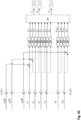
- Figure 7 illustrates an embodiment where a loudspeaker configuration is a mono sound system, i.e. a loudspeaker system with one discrete output channel.
- a loudspeaker configuration is a mono sound system, i.e. a loudspeaker system with one discrete output channel.
- determining the symmetry group audio signals may be omitted in its entirety in this case.
- all determined distance audios signals d_k resulting from the reverb operation 18a may be summed and optionally attenuated or amplified; and all virtual point audio signal components y_n resulting from the first reflections operation 12 may be summed, attenuated using the formula in dependence of the number of summed audio signals, and optionally further attenuated or amplified; and summed in the audio output of a loudspeaker together with the audio signal resulting from summing the distance audio signals, and together with the audio input signal x, which may also serve as audio input signal for a further reverberation audio signal determination method, as described with reference to figure 2 , figure 5 and figure 6A .
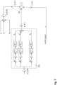
- Figure 8 illustrates an embodiment where a loudspeaker configuration is a stereo sound system, i.e. a loudspeaker system with two discrete output channels comprising the left (L) 30a and right (R) 30b side of a speaker setup in respect to the left and right-side ears of a (virtual) listener positioned in the middle.
- a system may be a pair of headphones.
- both the inverted and not-inverted versions for each distance audio signal is determined.
- the determination of symmetry group audio signals may be omitted in its entirety.
- the output of the first inverted version of a delay line is summed with the non-inverted version of the second delay line, the inverted version of the third delay line, etc. to form a discrete left-side output signal (L); and, the output of the first not-inverted version of a delay line is summed with the inverted version of the second delay line, the not-inverted version of the third delay line, etc. to form a discrete right-side output signal (R).
- the output of L ⁇ R and both L and R output signals may further be optionally attenuated or amplified before being fed to the L and R loudspeakers.
- Both L and R output signals of the initial audio input signal may further be optionally attenuated or amplified before being fed to the L and R loudspeakers.
- All L versions of the virtual point audio signal components resulting from the first reflections operation 12 are then summed, and all R version are summed, and both L and R are attenuated using the formula in dependence of the number of summed audio signals, and optionally further attenuated or amplified before being fed to the L and R loudspeakers.
- figure 7 and figure 8 represent possible embodiments which show the application of the described invention with regards to its backward compatibility with existing audio standards. Any variation of the output routing with regards to the audio signal process as described adjusted to a prior-art standard should be considered included herein.
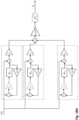
- the virtual points of the virtual object belong to symmetry groups of virtual points that can be determined as described in figure 9 .
- the virtual points are preferably equally distributed throughout and/or on the virtual object.
- a number N of virtual points may be defined and the virtual points may be understood to define the virtual object.
- the center point of the square plate coincides with virtual point #13. Since it is a square plate, a 90 degrees rotation around the center point will yield the same configuration again, i.e. square plate having the same position and orientation.
- the top right picture in figure 9 indicates for each virtual point to which symmetry group it belongs, i.e the figures between brackets indicate the symmetry groups for the virtual points.
- a single point, in figure 9 virtual point #13 belonging to symmetry group g 6 may form its own symmetry group in an embodiment.
- several or many single points may form their own symmetry group in an embodiment.
- geometrical or regular polygonal shapes tend to have fewer symmetry groups containing many points and irregular shapes tend to have more symmetry groups containing less points, i.e. a minimum of one point.
- Every virtual point n defined on the shape thus belongs to one symmetry group g. This constitutes that the conditions of the reverberation in the virtual object at the virtual points contained in one-and-the-same symmetry group will be the same, and that the virtual points contained in this symmetry group share the identical set of distances to any other points defined on the shape.
- Each symmetry group is associated with a set of one or more symmetry group distances.
- Figure 9 shows for each of the symmetry groups 1, 2, 3, 4, 5, 6, the associated symmetry group distances.
- a symmetry group g n may have more or less distances r g(n) ⁇ ->n than other groups, and many groups may share identical distances r n ⁇ ->n with other groups.
- v 343 m/sec.
- the described method comprises a highly efficient way to reduce the computational overhead required for generating a reverberation audio signal with desired coherence, density and smoothness, without losing the essential information that is unique to a virtual object of a particular shape and/or a particular size and materiality.
- the sum of the distance audio signals would not satisfy the criteria for smoothness of the reverberation tail; that is, a reverberation tail that would be generated by a feedback operation, such as described in figure 6A ; or more in general, a feedback-delay network (FDN) as is common to produce reverberation in the prior-art.
- the smoothness criteria for the modal density of the reverb is generally described to resemble a pink-noise signal with a faster dissipation of the higher frequencies compared to the lower frequencies in the time dimension. Since many identical and integer multiples of distances would be found among the set of distances generated as such, this would result in a dominance of certain frequencies F which disbalances the smoothness of the tail across the frequency range. Therefore such an approach to generate the reverberation tail would be disregarded in prior-art methods, as it would not satisfy the predetermined conditions.
- the number of signal paths required is greatly reduced X85 (600:7), as in comparison only 7 distinct distances for which 7 distance audio signals are to be determined, or 14 distance audio signals if two distance audio signals are determined for each distinct distance, in order to ensure the desired smoothness of the reverberation; while at the same time, keeping those distance values to generate the reverberation audio signal that contain the essential information unique to a shape of the virtual object.
- the amount of signal paths required for the reverberation is further reduced X2.5 (151:61) by introducing the intermediate step of summing the distance audio signals for the symmetry groups, as described in figure 10 , without any loss of quality/information in the resulting signal after the operation.
- the methods described herein thus comprise an efficient solution to optimize the computation power required by using the minimum of processing data and signal paths, and a novel way to satisfy the known criteria for density and smoothness of a high-quality reverberation signal, while introducing new qualities to the reverberation signal with regards to representing its shape and materiality, that are otherwise not attained with methods to produce artificial reverberation known-in-the-art.
- the virtual point resolution i.e. the number of defined points per shape
- the amount of distinct distances in the further set of one or more distances within the reverb operation 18 also increases, and more distance audio signals are to be generated.
- This increases the density of the reverb; that is, the 'time density' comprising the amount of echoes per second; and, the 'modal density' which relates to the amount of frequencies F(f 1 , f 2 , f 3 , etc.) across a frequency range, where each unique F is regarded the result of delay times ⁇ t which are not integer multiples of each other.
- the invention further comprises a novel way to optimise the modal density of a reverberation which has a virtual shape, by a balanced distribution of the polar opposites (+/-) of a particular distance r n ⁇ ->n .
- an inverted and time-delayed feedback signal amplifies the odd harmonics of F(f 1 , f 3 , f 5 , etc.) on the basis of the time delay ⁇ t
- an non-inverted time-delayed signal with feedback amplifies the even harmonics of the same F(f 2 , f 4 , f 6 , etc.) on the basis of the same time delay.
- the modal density of the resulting reverberation increases twofold for the same number of distances to be found for the same virtual point resolution of a shape.
- the virtual object is a square plate having four virtual points and therefore one symmetry group. There are two symmetry group distances for this one symmetry group. For each symmetry group distance two distance audio signals are determined, an inverted version and a non-inverted version.
- Each row in this table relates to a distinct distance in the further set of one or more distances.
- the distances are indicated by associated time delays.
- each column relates to a symmetry group signal.
- ⁇ t (ms) Groups (g) 1.1 1.2 ⁇ t1 -1 +1 ⁇ t2 +1 -1
- the inverted version of the distance audio signal for distance ⁇ t1 and the non-inverted version of the distance audio signal for distance ⁇ t2 are added together.
- the non-inverted version of the distance audio signal for distance ⁇ t1 and the inverted version of the distance audio signal for distance ⁇ t2 are added together.
- a shape is a plate of equal edges but of unequal length and width, with four virtual points and two symmetry groups. Three distinct distances are found in the further set of one or more distances and for each distinct distance, two distance audio signals are determined.
- the equal distribution across polar opposites of distance r n- ⁇ -> n+ according to figure 11B gives ⁇ t (ms) Groups (g) 1.1 1.2 2.1 2.2 ⁇ t1 0 0 -1 +1 ⁇ t2 +1 -1 +1 -1 t3 -1 +1 0 0 0 0
- a shape is a plate with unequal sides, length and width, with four virtual points and four symmetry groups.
- each virtual point defined on the shape is its own symmetry group.
- a symmetry group has only one version of itself instead of two. Six unique distances are found in the further set of one or more distances.
- Figure 12 is a flow process for a 'value filter' operation 34 to obtain the desired time delays in dependence of the distances between virtual points, as described in figure 9 ; and, a 'time density scaler' operation 36 to automate optimizing of the required time density of the reverberation based on a variable threshold.
- the steps until the step "determine symmetry groups" may be performed in the value filter operation 34 and the steps following this step in each iteration may be performed in the time density scaler operation 36.
- the step to determine positions of virtual points may involve receiving a lattice and shape data.
- the output of this step is an NxN-dimensional array where each element holds distance values of the virtual point to all other virtual points.
- the virtual point numbering and coordinates (x, y, z) relating to the virtual point positions in a virtual space may be generated from a custom shape script file.
- a simple virtual object script file includes a method where vec3 objects are specified.
- a computer program may then extract the values in the function call and generate the virtual point coordinates.
- This initial matrix can be obtained by, for each virtual point out of the plurality of virtual points, defining a set of one or more virtual distances comprising the respective virtual distances between the virtual point in question and the respective other virtual points out of the plurality of virtual points.
- the set of one or more virtual distances associated with virtual point #1 are indicated on row "1”
- the set of one or more virtual distances associated with virtual point #2 are indicated on row "2”
- et cetera et cetera.
- the initial matrix is then passed through a multiplicity filter to remove some of the delay times.
- the filters may be applied per virtual point, where one virtual point is represented by each horizontal row in the matrix.
- equality is determined by taking the absolute value of the difference of the delay times and checking if the difference is less than the time of one sample, according to sample rate. Such almost identical distances are thus not treated as distinct distances.
- delay times i.e. distances, that are integer multiples of other delay times are filtered out as well.
- the distance between virtual point p1 and virtual point p3 is filtered out as it is twice the value of the distance between virtual point p1 and virtual point p2
- Such virtual point specific set may also be arrived at by first, for each set of one or more distances associated with a virtual point, i.e. for each row in the initial matrix, removing distances that are integer multiples of any other distance in the set, i.e. row in question, to obtain a further set of one or more distances associated with the virtual point.
- the virtual-point specific set may then be determined as the distinct distances in each further set.
- the virtual point specific set for point 1 then comprises 0.972, 1.374 and 2.173.
- the value set of the matrix sorts the distinct delay times, i.e. the distinct distances, in ascending order from shortest to longest delay line. These distinct delay times are also referred to herein as the distinct distances of the further set of one or more distances. After these distinct distances have been found, other characteristics may be analyzed such as the occurrence of the delay time associated with a distinct distance per symmetry group.
- the virtual points having the same virtual point specific sets of distances are determined to belong to a symmetry group.
- point 3 has as virtual point specific set of distances: 0.972, 1.374 and 2.173, which is the same as the virtual point specific set for point 1. Therefore, point 1 and 3 belong to the same symmetry group.
- the time delay of 0.972 ms (i.e. virtual distance 0.333 m) is associated with two symmetry groups, namely symmetry group 1, consisting of virtual points 1-, 2+, 3-, 4+, 6-, 7+, 8-, 9+ and symmetry group 2 consisting of virtual point 5- ,
- a new matrix is created where on the horizontal axis all symmetry groups are placed in two versions 1.1 1.2 2.1 2.2 3.1 3.2 etc. If a group consists of only 1 virtual point, there is only one version of the group, and thus the group only appears once in the matrix. On the vertical axis all the distinct distances in the further set of one or more distances formed by all symmetry group distances, which distinct distances are expressed as delay times, are sorted from shortest (top) to longest (down). The polar opposites (+/-) are then added to the matrix in a straight-forward chess-board like fashion. Finally, the virtual points within each symmetry group are distributed alternating between group n.1 and n.2 according to the process as described in figures 11A-C .
- the second step of the command chain comprises the 'time density scaler' operation, referring to building block 36 in figure 3 .
- the time density value for a symmetry group of virtual points may be performed as follows. Each symmetry group of virtual points is associated with one or more symmetry group distances. Further, for each symmetry group distance, one or more distance audio signals are determined using a time delay operation (see 64/72 in figure 6A ).
- ⁇ t 1 is the time delay (in seconds) introduced by the time delay operation for determining the one or more distance audio signals for a first distance out of the symmetry group distance
- ⁇ t 2 is the time delay introduced by the time delay operation for determining the one or more distance audio signals for a second distance out of the symmetry group distance, et cetera.
- Q denotes the number of symmetry group distances for the symmetry group for which the density index is determined.
- the given time density per symmetry group is compared to a variable threshold. If the calculated value for di is lower than the threshold, it does not satisfy the filter and commands the process to increase the virtual point resolution and triggers a rerun of the command chain until the density index for each symmetry group is equal to or higher than the threshold, and thus satisfies the filter.
- the amount of echoes per second to satisfy enough density of the reverberation is generally considered to be a 1000 s -1 but may be as high as 10000 s -1 , depending on the type and character of the audio input signal to the audio signal process.
- the time density threshold is required to be a variable parameter that may be adjusted by a user dependent on various circumstances.
- a system for generating reverberation in a virtual object adjusts automatically to the most optimal density condition for a given virtual object in a given condition.
- parameters such as delay times are carefully chosen to satisfy criteria of time density.
- the invention provides a novel way to require optimal time density without pre-requiring a fixed set of values, such as the chosen delay times in a system, and where instead, such values may depend on the attributes of a shape, i.e. reverberation in a virtual object with a dimensional shape, size and materiality.
- Figure 13 illustrates a flow process for a 'sample rate interpolator' operation 32 to obtain desired low-pass filtering included in the first reflections operation 12 and the reverb operation 18; specifically in the case of high and ultra-high frequency cut-off values f c that may occur in dependence of set conditions of a reverberation, including the speed of sound travelling through a medium, the temperature, humidity and other factors; and, in dependence of the size and the virtual point resolution of a virtual object, which determines the scale of the distances between the virtual points.
- the Nyquist frequency practically determines the upper threshold of the assignable cut-off frequency in a digital low-pass filter, which means filtering above the Nyquist will not yield an audible effect. Nevertheless, the effect of the distancedependent damping function as described in figure 6A , and which may involve a value for f c above the Nyquist frequency, may also imply a significant audible effect from the attenuation of frequencies below the Nyquist frequency.
- a command flow takes into account the relation of the sample rate of the audio output device connected to (or as part of) the computer processing unit running a programme or code portion and the generated frequency cut-off values in first reflection operations 12 and reverb 18, by locally increasing the sample rate to complete the desired filtering operation, and then decreasing the sample rate back to the sample rate of the audio output device, by means of sample interpolation.
- a second step comprises a first filter to determine if further action is required with regards to sample interpolation. If the obtained value for f c is larger than the Nyquist frequency it does not satisfy the filter, which commands the process to locally increase the sample rate by interpolation until it satisfies the filter and commands to perform the low-pass filtering process at the locally optimised sample rate.
- a second filter checks if the local sample rate matches the sample rate of the audio output device and if it does not satisfy the filter, it decreases the local sample rate by interpolation until the sample matches the sample rate of the audio output device.
- Figure 14 depicts a user interface according to an embodiment of the invention.
- An embodiment of the method comprises generating a user interface as described herein.
- a user interface for the described system comprises a module to control the virtual object, e.g. its position with respect to an observer and/or "vantage-point", the shape of the virtual object, the material of which the virtual object consists, the conditions of the selected medium for sound propagation, the attributes of the reverb itself, several other attributes such as the resonance resulting from standing waves within the virtual object of a particular shape, and the audio output of the audio signal process, which may include a master output level, as well as send levels for an audio output signal, or "audio mix-down", from the audio signal process to provide as an input audio signal to other audio signal processes determined for other virtual objects.
- the depicted user interface comprises an input section that enables a user to control the audio output signal or audio mix-down from other audio signal processes determined for other virtual objects as an input audio signal for the audio signal process determined for said virtual object using input channels.
- the input channels may comprise of multiple audio channels, either receiving an audio signal from an audio signal process determined for another virtual object, optionally by performing a method as described, or external audio sources, together combined as the input audio signal for the audio signal process determined for said virtual object.
- the user interface enables a user to control the amplification of each input channel, e.g. by using gain knobs.
- the user interface may further comprise an output section that enables a user to route the summed audio output signals, or audio mix-down, of the audio signal process determined for said virtual object as an input audio signal to determine audio signal processes for other virtual objects.
- the output module may further comprise a master level fader, which may determine the level of the optional attenuation (value 'a') of the audio output signals of the audio signal process fed to discrete loudspeakers, such as described in figure 5 .
- a master level fader may determine the level of the optional attenuation (value 'a') of the audio output signals of the audio signal process fed to discrete loudspeakers, such as described in figure 5 .
- the user interface may further comprise a virtual object definition section that enables a user to input parameters relating to the virtual object, such as its shape, e.g. selecting a shape by means of a drop-down menu; and/or whether the virtual object is hollow or solid by means of an on/off button; and/or adjusting the scale, i.e. the size of the virtual object by means of a knob; and/or its dimensions, e.g. its Cartesian dimensions by means of number boxes for dimensions x, y and z; and/or a rotation; and/or a resolution to determine the amount, i.e. the density, of virtual points defined on the shape of the virtual object by means of a number box. This allows a user to control the amount of required calculations in the audio signal process determined for the virtual object.
- parameters relating to the virtual object such as its shape, e.g. selecting a shape by means of a drop-down menu; and/or whether the virtual object is hollow or solid by means of an on/off button; and/or
- the input means for inputting parameters relating to rotation may be presented as endless rotational knobs for dimensions x, y and z
- the user interface may further comprise a position section that enables a user to input parameters relating to the position of the virtual object.
- the position of the shape in 3-dimensional space may be expressed in Cartesian coordinates +/- x, y, z wherein the virtual center of the space is denoted as 0, 0, 0; and which may be presented as a visual 3-dimensional field that one can place and move a virtual object within.
- This 3-dimensional control field may be scaled in size by adjusting the radius of the field.
- the discrete audio output signals for each loudspeaker resulting from the reverberation audio signal process determined for the virtual object may thus be automatically controlled by i) the modelling of the virtual object's shape, ii) the rotation of the shape in 3-dimensional space and iii) the position of the shape in 3-dimensional space.
- the user interface may further comprise an attributes section that enables a user to control various parameters, such as a knob to adjust the bandwidth and amount of resonance which determines the attenuation of the optional feedback signal (value 'b') in the resonance operation 20 as described in figure 16A ; a knob for scaling the perceived distance, which determines the multiplication factor x in the formula determining attenuation operation of the distance operation 26 as described in figure 16D ; a knob for scaling the perceived elevation, which determines the multiplication factor x in the formula determining attenuation operation of either the depth operation 22 as described in figure 16B or the height operation 26 as described in figure 16C ; and, a knob for scaling the amount of Doppler effect, which is a scaler to modify the formula determining the second time delay of the distance operation 26 as described in figure 16D .
- a knob to adjust the bandwidth and amount of resonance which determines the attenuation of the optional feedback signal (value 'b') in the resonance operation 20 as described in figure 16A ; a knob for
- the user interface may further comprise a section to select a material for the virtual object by means of a drop-down menu with several pre-programmed options.
- the choice of material determines a chosen set of ISO354 values in the absorption filter operations as described in figure 6A .
- An 'absorption knob' and a 'reflectivity knob' provide proportional scalers of the absorption coefficients from the chosen ISO354 values, to increase the absorption characteristic of the chosen material; or, to decreases the absorption characteristic of the chosen material, so that the resulting reflections and reverberation will constitute less absorption and more dense reflections of the sound.
- the user interface may further comprise a section to control the conditions of a chosen medium by means of a drop-down menu with several pre-programmed options.
- the selection of a medium which in an embodiment may be air, may constitute several custom options specific to the medium which are considered parameters of behaviour of sound propagating in the particular medium, such as in the case of the medium of air, a number box to set the value in C of the temperature and a knob to increase/decrease the humidity.
- the speed of sound is a resulting value from the choice of medium and related parameters, but may be manually adjusted in a controllable number box to deviate from the calculated standard.
- the set parameter values in the conditions section determine the frequency-dependent attenuation of the low-pass filter operations and determine the time delays in the time delay operations of the first reflections operations 12 and reverb operations 18 as described in figure 6A ; determine the calculations of the time delays in the value filtering operation as described in figure 12 ; and, determine the frequency cut-off in relation to the Nyquist frequency as described in figure 13 .
- the user interface may further comprise a section to control attributes of the reverb, such as a knob for controlling the output gain of the first reflections, which determines the level of the optional attenuation (value 'a') of the audio signal components resulting from the first reflections operation 12 as described in figure 6C ; a knob for controlling the output gain of the reverb tail, which determines the level of the optional attenuation (value 'b') of the audio signal components resulting from the reverb operation 18 as described in figure 6C ; a knob for controlling the decay time of the reverb, which determines the coefficient x in the formula determining attenuation operation of the reverb operation 18 as described in figure 6A ; a knob for controlling the damping of the reverb, which may modify and/or scale the coefficient y in the formula determining the frequency cut-off in low-pass filtering operation as part of the first reflections 12 and/or reverb operation 18 and to further modify, that is increase or decrease the effect of the correction formula for high-
- the user input that is received through the user interface may be used to determine appropriate values for the parameters according to methods described herein. All functional operations of the reverberation system are thus translated to front-end user properties, i.e. audible manipulations of sound sources reverberating in a virtual space with a dimensional shape, size and materiality.
- Figure 15 depicts a block diagram illustrating a data processing system according to an embodiment.
- the data processing system 100 may include at least one processor 102 coupled to memory elements 104 through a system bus 106.
- the data processing system may store program code within memory elements 104.
- the processor 102 may execute the program code accessed from the memory elements 104 via a system bus 106.
- the data processing system may be implemented as a computer that is suitable for storing and/or executing program code. It should be appreciated, however, that the data processing system 100 may be implemented in the form of any system including a processor and a memory that is capable of performing the functions described within this specification.
- the memory elements 104 may include one or more physical memory devices such as, for example, local memory 108 and one or more bulk storage devices 110.
- the local memory may refer to random access memory or other non-persistent memory device(s) generally used during actual execution of the program code.
- a bulk storage device may be implemented as a hard drive or other persistent data storage device.
- the processing system 100 may also include one or more cache memories (not shown) that provide temporary storage of at least some program code in order to reduce the number of times program code must be retrieved from the bulk storage device 110 during execution.
- the input and the output devices may be implemented as a combined input/output device (illustrated in figure 15 with a dashed line surrounding the input device 112 and the output device 114).
- a combined device is a touch sensitive display, also sometimes referred to as a "touch screen display” or simply "touch screen”.
- input to the device may be provided by a movement of a physical object, such as e.g. a stylus or a finger of a user, on or near the touch screen display.
- a network adapter 116 may also be coupled to the data processing system to enable it to become coupled to other systems, computer systems, remote network devices, and/or remote storage devices through intervening private or public networks.
- the network adapter may comprise a data receiver for receiving data that is transmitted by said systems, devices and/or networks to the data processing system 100, and a data transmitter for transmitting data from the data processing system 100 to said systems, devices and/or networks.
- Modems, cable modems, and Ethernet cards are examples of different types of network adapter that may be used with the data processing system 100.
- the data processing system 100 may represent a first reflections module 12 and/or absorption filter 16 and/or reverb module 18 and/or resonance module 20 and/or depth module 22 and/or height module 24 and/or distance module 26 and/or panning system 28 as described herein.
- the data processing system 100 may represent a shape generator 30 and/or sample rate interpolator 32 and/or value filter 34 and/or time density scaler 36 as described herein.
- the inventor acknowledges la Mgvdliashvili and Dr. Amira Val Baker for their contributions to this disclosure.
Landscapes
- Engineering & Computer Science (AREA)
- Physics & Mathematics (AREA)
- Acoustics & Sound (AREA)
- Multimedia (AREA)
- Signal Processing (AREA)
- Stereophonic System (AREA)
- Reverberation, Karaoke And Other Acoustics (AREA)
Claims (17)
- Verfahren zum Erzeugen eines mit einem virtuellen Objekt verbundenen Nachhall-Audiosignals, wobei das Verfahren Folgendes aufweistSpeichern einer Darstellung des virtuellen Objekts, wobei die Darstellung eine Vielzahl von virtuellen Punkten definiert, die das virtuelle Objekt bilden, wobei die virtuellen Punkte jeweilige virtuelle Positionen in Bezug zueinander haben und wobei die virtuellen Punkte zu Symmetriegruppen von virtuellen Punkten gehören, wobei die Symmetriegruppen von virtuellen Punkten erhältlich sind durch- für jeden virtuellen Punkt aus der Vielzahl der virtuellen Punkte, Definieren eines Satzes von einer oder mehreren virtuellen Entfernungen, die die jeweiligen virtuellen Entfernungen zwischen dem fraglichen virtuellen Punkt und den jeweiligen anderen virtuellen Punkten aus der Vielzahl der virtuellen Punkte umfassen, und- für jeden Satz von einer oder mehreren Entfernungen, die mit einem virtuellen Punkt verbunden sind, Entfernen von Entfernungen, die ganzzahlige Vielfache jeder anderen Entfernung in dem Satz sind, um einen weiteren Satz von einer oder mehreren Entfernungen zu erhalten, die mit dem virtuellen Punkt verbunden sind; und- für jeden weiteren Satz von einer oder mehreren Entfernungen, die mit einem virtuellen Punkt verbunden sind, Bestimmen der verschiedenen Entfernungen in dem betreffenden weiteren Satz, um einen für den virtuellen Punkt spezifischen Satz von einer oder mehreren Entfernungen zu bilden, die mit dem virtuellen Punkt verbunden sind; und- Bestimmen virtueller Punkte, die dieselben jeweiligen für virtuelle Punkte spezifischen Sätze von einer oder mehreren Entfernungen aufweisen, um eine Symmetriegruppe virtueller Punkte zu bilden, wobei die Symmetriegruppe virtueller Punkte somit mit einem Satz von einem oder mehreren Symmetriegruppen-Entfernungen verbunden ist, der derselbe ist wie die für virtuelle Punkte spezifischen Sätze ihrer virtuellen Punkte;
wobeidie Sätze von einer oder mehreren Symmetriegruppen-Entfernungen, die jeweils mit Symmetriegruppen verbunden sind, zusammen einen weiteren Satz von einer oder mehreren Entfernungen bilden,wobei das Verfahren ferner aufweistEmpfangen und/oder Speichern und/oder Erzeugen eines Eingangsaudiosignals, undfür jeden virtuellen Punkt die Bestimmung einer Audiosignalkomponente des virtuellen Punkts auf der Grundlage des Eingangsaudiosignals oder einer gefilterten Version davon undKombinieren der so erhaltenen virtuellen Punkt-Audiosignalkomponenten, um ein zusammengesetztes Audiosignal zu erhalten, undBestimmen von einem oder mehreren Entfernungs-Audiosignalen für jede bestimmte Entfernung in dem weiteren Satz von einer oder mehreren Entfernungen, basierend auf dem zusammengesetzten Audiosignal,Bestimmen des Nachhall-Audiosignals auf der Grundlage des einen oder der mehreren Entfernungs-Audiosignale und der Audiosignalkomponenten des virtuellen Punktes. - Verfahren nach Anspruch 1, ferner aufweisendBestimmen von einem oder mehreren Symmetriegruppen-Audiosignalen für jede Symmetriegruppe auf der Grundlage der ermittelten Entfernungs-Audiosignale, undBestimmung des Nachhall-Audiosignals auf der Grundlage der Audiosignale der Symmetriegruppe und der Audiosignalkomponenten des virtuellen Punktes.
- Verfahren nach Anspruch 1 oder 2, wobei die Bestimmung einer Audiosignalkomponente eines virtuellen Punktes für jeden virtuellen Punkt auf der Grundlage des Eingangsaudiosignals oder einer gefilterten Version davon Folgendes aufweist
für jeden virtuellen Punkt, Durchführen einer für den virtuellen Punkt spezifischen Operation an dem Eingangsaudiosignal oder einer modifizierten, z.B. gefilterten, Version davon, wobei das Durchführen der für den virtuellen Punkt spezifischen Operation das Durchführen einer Zeitverzögerungsoperation umfasst, die eine Zeitverzögerung einführt, wobei die eingeführte Zeitverzögerung ungefähr gleich einer virtuellen Entfernung zwischen dem fraglichen virtuellen Punkt und einer virtuellen Schallquelle geteilt durch eine Schallgeschwindigkeit ist. - Verfahren nach einem der vorhergehenden Ansprüche, wobei die Bestimmung eines oder mehrerer Entfernungs-Audiosignale für jede eindeutige Entfernung in dem weiteren Satz von einer oder mehreren Entfernungen Folgendes aufweistBestimmen eines ersten Entfernungs-Audiosignals und eines zweiten Entfernungs-Audiosignals für jede bestimmte Entfernung in dem weiteren Satz von einer oder mehreren Entfernungen, wobeiBestimmen des ersten Entfernungs-Audiosignals für eine bestimmte Entfernung, umfassend das Modifizieren des zusammengesetzten Audiosignals durch Ausführen einer Zeitverzögerungsoperation, die eine Zeitverzögerung einführt, einer Signaldämpfungsoperation, einer Tiefpassfilteroperation und einer Signalrückkopplungsoperation, und wobeidas Bestimmen des zweiten Entfernungs-Audiosignals für die bestimmte Entfernung das Modifizieren des zusammengesetzten Audiosignals durch Ausführen einer zweiten Zeitverzögerungsoperation, die eine zweite Zeitverzögerung einführt, einer Signalinvertierungsoperation, einer Signaldämpfungsoperation, einer Tiefpassfilteroperation und einer zweiten Signalrückkopplungsoperation umfasst.
- Verfahren nach dem vorhergehenden Anspruch, wobei die durch die erste Zeitverzögerungsoperation eingeführte Zeitverzögerung gleich der bestimmten Entfernung geteilt durch eine Schallgeschwindigkeit ist.
- Verfahren nach Anspruch 2 und Anspruch 4 oder 5, wobei das Bestimmen ein oder mehrerer Symmetriegruppen-Audiosignale für jede Symmetriegruppe auf der Grundlage der Entfernungs-Audiosignale aufweistBestimmen eines ersten Symmetriegruppen-Audiosignals und eines zweiten Symmetriegruppen-Audiosignals für jede Symmetriegruppe, wobeiBestimmen der ersten und zweiten Symmetriegruppen-Audiosignale aufweist: Auswählen eines Entfernungs-Audiosignals aus jedem Paar von ersten und zweiten Entfernungs-Audiosignalen, wobei jedes Paar für eine jeweilige Entfernung aus dem Satz von einer oder mehreren Symmetriegruppen-Entfernungen, die der fraglichen Symmetriegruppe zugeordnet sind, bestimmt worden ist, und Kombinieren der ausgewählten Entfernungs-Audiosignale, um das erste Symmetriegruppen-Audiosignal zu bestimmen, und Kombinieren der nicht ausgewählten Entfernungs-Audiosignale aus jedem Paar von ersten und zweiten Entfernungs-Audiosignalen, um das zweite Symmetriegruppen-Audiosignal zu bestimmen.
- Verfahren nach einem der vorhergehenden Ansprüche 2 bis 6, wobei die Bestimmung des Audiosignals auf der Grundlage der Symmetriegruppen-Audiosignale und der Audiosignalkomponenten des virtuellen Punktes Folgendes aufweistKombinieren der Audiosignale der Symmetriegruppe mit den Audiosignalkomponenten des virtuellen Punktes, um das Nachhall-Audiosignal zu bestimmen, wobeidie Kombination der Audiosignale der Symmetriegruppe mit den Audiosignalkomponenten des virtuellen Punktes zur Bestimmung des Audiosignals umfasstBestimmen modifizierter Audiosignalkomponenten, wobei das Bestimmen modifizierter Audiosignalkomponenten das Hinzufügen des ersten oder zweiten Symmetriegruppen-Audiosignals der betreffenden Symmetriegruppe zu jeder Audiosignalkomponente eines virtuellen Punktes umfasst, die für einen zu einer Symmetriegruppe gehörenden virtuellen Punkt bestimmt wurde.
- Verfahren nach einem der vorangehenden Ansprüche, ferner aufweisend: Durchführen des Verfahrens nach einem der vorangehenden Ansprüche zur Erzeugung eines weiteren Nachhall-Audiosignals für ein weiteres virtuelles Objekt, wobei
das ermittelte Nachhall-Audiosignal, das dem virtuellen Objekt zugeordnet ist, als Eingangsaudiosignal verwendet wird. - Verfahren nach dem vorhergehenden Anspruch, ferner aufweisend Kombinieren des dem virtuellen Objekt zugeordneten Nachhall-Audiosignals und des weiteren Nachhall-Audiosignals, das dem weiteren virtuellen Objekt zugeordnet ist, und optional
Bereitstellung der Kombination für einen oder mehrere Lautsprecher. - Verfahren nach einem der vorhergehenden Ansprüche, ferner aufweisend Bereitstellen des ermittelten Audiosignals für einen oder mehrere Lautsprecher.
- Verfahren nach dem vorhergehenden Anspruch, aufweisend
Bereitstellen der modifizierten Audiosignalkomponenten an einen oder mehrere Lautsprecher umfasst Bereitstellen der modifizierten Audiosignalkomponenten an ein Panning-System, das so konfiguriert ist, dass es die modifizierten Audiosignalkomponenten an eine Vielzahl von Lautsprechern verteilt. - Verfahren nach einem der vorhergehenden Ansprüche, das ferner Folgendes aufweistFiltern des Eingangsaudiosignals, bevor für jeden virtuellen Punkt eine Audiosignalkomponente des virtuellen Punkts bestimmt wird, wobei das Filtern des Eingangsaudiosignals Folgendes umfasstAnwenden eines Multibandfilters, der die Dämpfung der jeweiligen Frequenzbänder im Eingangsaudiosignal unter Verwendung der jeweiligen Dämpfungskoeffizienten umfasst, wobei die jeweiligen Dämpfungskoeffizienten auf der Grundlage eines Materials des virtuellen Objekts bestimmt werden.
- Verfahren nach einem der vorhergehenden Ansprüche, wobei die Bestimmung eines oder mehrerer Entfernungs-Audiosignale für jede eindeutige Entfernung in dem weiteren Satz von einer oder mehreren Entfernungen Folgendes aufweistBestimmen eines Entfernungs-Audiosignals für jede bestimmte Entfernung in dem weiteren Satz von einer oder mehreren Entfernungen, umfassend das Modifizieren des zusammengesetzten Audiosignals durch Ausführen einer Zeitverzögerungsoperation, die eine Zeitverzögerung einführt, einer Signaldämpfungsoperation, einer Tiefpassfilteroperation und einer Signalrückkopplungsoperation, wobei das Verfahren ferner umfasstBestimmen eines Dichteindexes für mindestens eine Symmetriegruppe virtueller Punkte, ferner mit- Bestimmen für jede Entfernung aus dem Satz von einer oder mehreren Symmetriegruppenentfernungen, die mit der mindestens einen Symmetriegruppe verbunden sind, wie viele Rückkopplungsoperationen zum Bestimmen eines Entfernungs-Audiosignals für die fragliche Entfernung pro Zeiteinheit durchgeführt werden, zum Beispiel durch Teilen der Zeiteinheit durch die Zeitverzögerung, die durch die Zeitverzögerungsoperation eingeführt wird, die zum Bestimmen des fraglichen Entfernungsaudiosignals durchgeführt wird, wodurch für jede Entfernung aus dem Satz von einer oder mehreren Symmetriegruppenentfernungen, die mit der mindestens einen Symmetriegruppe verbunden sind, die jeweilige Anzahl von durchgeführten Rückkopplungsoperationen erhalten wird, und- Addieren der jeweiligen Anzahl der durchgeführten Rückkopplungsoperationen, um den Dichteindex für die Symmetriegruppe der virtuellen Punkte zu erhalten, wobei das Verfahren ferner aufweist- Empfangen eines Schwellenwerts für den Dichteindex, und- Bestimmen, dass der ermittelte Dichteindex niedriger als der Schwellenwert ist, und- basierend auf dieser Bestimmung Ändern der gespeicherte Darstellung durch Erhöhung der Anzahl der virtuellen Punkte, die das virtuelle Objekt bilden.
- Verfahren nach einem der Ansprüche 4-13, wobei der Tiefpassfiltervorgang Folgendes umfasst- Feststellen, dass das tiefpassgefilterte Signal mit einer Nyquist-Frequenz verbunden ist, die niedriger ist als eine Grenzfrequenz, die mit dem Tiefpassfilterbetrieb verbunden ist, und- basierend auf dieser Bestimmung, Aufwärtsabtastung des zu filternden Signals, so dass es einer Nyquist-Frequenz zugeordnet ist, die höher als oder gleich der Grenzfrequenz ist, und- Tiefpassfiltern des hochabgetasteten Signals, und,- optionale Bestimmen, dass das gefilterte Signal mit einer höheren Abtastrate als einer Ausgangsabtastrate verbunden ist, wobei die Ausgangsabtastrate die Abtastrate ist, die von einem Ausgabesystem ausgegeben werden kann, und, basierend auf dieser Bestimmung, Abwärtsabtastung des gefilterten Signals.
- Computer miteinem computerlesbaren Speichermedium mit darin verkörpertem computerlesbarem Programmcode, undeinem Prozessor, vorzugsweise einem Mikroprozessor, der mit dem computerlesbaren Speichermedium verbunden ist, wobei der Prozessor als Reaktion auf die Ausführung des computerlesbaren Programmcodes so konfiguriert ist, dass er das Verfahren nach einem der vorhergehenden Ansprüche durchführt.
- Computerprogramm oder eine Folge von Computerprogrammen, das/die mindestens einen Softwarecodeabschnitt oder ein Computerprogrammprodukt umfasst, das mindestens einen Softwarecodeabschnitt speichert, wobei der Softwarecodeabschnitt, wenn er auf einem Computersystem ausgeführt wird, so konfiguriert ist, dass er das Verfahren nach einem der vorangehenden Ansprüche 1-14 ausführt.
- Nicht-transitorisches, computerlesbares Speichermedium, das mindestens einen Softwarecodeabschnitt speichert, wobei der Softwarecodeabschnitt, wenn er von einem Computer ausgeführt oder verarbeitet wird, so konfiguriert ist, dass er das Verfahren nach einem der vorangehenden Ansprüche 1-14 durchführt.
Applications Claiming Priority (2)
| Application Number | Priority Date | Filing Date | Title |
|---|---|---|---|
| NL2026361A NL2026361B1 (en) | 2020-08-28 | 2020-08-28 | Method for generating a reverberation audio signal |
| PCT/NL2021/050523 WO2022045888A1 (en) | 2020-08-28 | 2021-08-26 | Method for generating a reverberation audio signal |
Publications (3)
| Publication Number | Publication Date |
|---|---|
| EP4205103A1 EP4205103A1 (de) | 2023-07-05 |
| EP4205103C0 EP4205103C0 (de) | 2024-05-29 |
| EP4205103B1 true EP4205103B1 (de) | 2024-05-29 |
Family
ID=73402032
Family Applications (1)
| Application Number | Title | Priority Date | Filing Date |
|---|---|---|---|
| EP21759422.5A Active EP4205103B1 (de) | 2020-08-28 | 2021-08-26 | Verfahren zur erzeugung eines nachhallaudiosignals |
Country Status (8)
| Country | Link |
|---|---|
| US (1) | US20230306953A1 (de) |
| EP (1) | EP4205103B1 (de) |
| JP (1) | JP2023539220A (de) |
| KR (1) | KR20230058443A (de) |
| AU (1) | AU2021333078A1 (de) |
| CA (1) | CA3192019A1 (de) |
| NL (1) | NL2026361B1 (de) |
| WO (1) | WO2022045888A1 (de) |
Families Citing this family (5)
| Publication number | Priority date | Publication date | Assignee | Title |
|---|---|---|---|---|
| NL2028723B1 (en) | 2021-07-14 | 2023-01-20 | Liquid Oxigen Lox B V | Environmental sound loudspeaker |
| EP4174846A1 (de) * | 2021-10-26 | 2023-05-03 | Koninklijke Philips N.V. | Audiovorrichtung und verfahren zum betrieb davon |
| GB202206430D0 (en) * | 2022-05-03 | 2022-06-15 | Nokia Technologies Oy | Apparatus, methods and computer programs for spatial rendering of reverberation |
| JP7783499B2 (ja) * | 2022-09-14 | 2025-12-10 | 株式会社カプコン | ゲームプログラム、およびゲーム装置 |
| KR102830096B1 (ko) | 2023-11-30 | 2025-07-03 | 주식회사 엠박스 | 음장 데이터 분석과 음선 추적법을 이용한 공간음향 렌더링을 위한 오디오 잔향 구현 시스템 및 이에 의한 오디오 잔향 구현 방법 |
Family Cites Families (10)
| Publication number | Priority date | Publication date | Assignee | Title |
|---|---|---|---|---|
| US20030007648A1 (en) * | 2001-04-27 | 2003-01-09 | Christopher Currell | Virtual audio system and techniques |
| US7949141B2 (en) * | 2003-11-12 | 2011-05-24 | Dolby Laboratories Licensing Corporation | Processing audio signals with head related transfer function filters and a reverberator |
| US20080273708A1 (en) | 2007-05-03 | 2008-11-06 | Telefonaktiebolaget L M Ericsson (Publ) | Early Reflection Method for Enhanced Externalization |
| JP2013073027A (ja) * | 2011-09-28 | 2013-04-22 | Panasonic Corp | 音響再生装置および音響再生方法 |
| US9602927B2 (en) | 2012-02-13 | 2017-03-21 | Conexant Systems, Inc. | Speaker and room virtualization using headphones |
| EP2834808B1 (de) | 2012-03-30 | 2019-08-07 | ETH Zurich | Wiedergabesystem für schallwellen |
| JP6511775B2 (ja) | 2014-11-04 | 2019-05-15 | ヤマハ株式会社 | 残響音付加装置 |
| EP3018918A1 (de) * | 2014-11-07 | 2016-05-11 | Fraunhofer-Gesellschaft zur Förderung der angewandten Forschung e.V. | Vorrichtung und Verfahren zur Erzeugung von Ausgangssignalen auf Basis eines Audioquellensignals, Tonwiedergabesystems und Lautsprechersignals |
| EP4002888B1 (de) | 2015-02-12 | 2024-09-25 | Dolby Laboratories Licensing Corporation | Kopfhörervirtualisierung |
| US10524080B1 (en) * | 2018-08-23 | 2019-12-31 | Apple Inc. | System to move a virtual sound away from a listener using a crosstalk canceler |
-
2020
- 2020-08-28 NL NL2026361A patent/NL2026361B1/en active
-
2021
- 2021-08-26 US US18/023,295 patent/US20230306953A1/en not_active Abandoned
- 2021-08-26 JP JP2023513215A patent/JP2023539220A/ja active Pending
- 2021-08-26 CA CA3192019A patent/CA3192019A1/en active Pending
- 2021-08-26 KR KR1020237009997A patent/KR20230058443A/ko active Pending
- 2021-08-26 AU AU2021333078A patent/AU2021333078A1/en active Pending
- 2021-08-26 WO PCT/NL2021/050523 patent/WO2022045888A1/en not_active Ceased
- 2021-08-26 EP EP21759422.5A patent/EP4205103B1/de active Active
Also Published As
| Publication number | Publication date |
|---|---|
| EP4205103C0 (de) | 2024-05-29 |
| AU2021333078A1 (en) | 2023-03-16 |
| EP4205103A1 (de) | 2023-07-05 |
| NL2026361B1 (en) | 2022-04-29 |
| WO2022045888A1 (en) | 2022-03-03 |
| US20230306953A1 (en) | 2023-09-28 |
| CA3192019A1 (en) | 2022-03-03 |
| KR20230058443A (ko) | 2023-05-03 |
| JP2023539220A (ja) | 2023-09-13 |
Similar Documents
| Publication | Publication Date | Title |
|---|---|---|
| EP4205103B1 (de) | Verfahren zur erzeugung eines nachhallaudiosignals | |
| JP7683101B2 (ja) | 少なくとも一つのフィードバック遅延ネットワークを使ったマルチチャネル・オーディオに応答したバイノーラル・オーディオの生成 | |
| US10555109B2 (en) | Generating binaural audio in response to multi-channel audio using at least one feedback delay network | |
| Wendt et al. | A computationally-efficient and perceptually-plausible algorithm for binaural room impulse response simulation | |
| De Sena et al. | Efficient synthesis of room acoustics via scattering delay networks | |
| US8908875B2 (en) | Electronic device with digital reverberator and method | |
| EP2153695A2 (de) | Frühreflexionsverfahren für erweiterte externalisierung | |
| Gardner | A realtime multichannel room simulator | |
| Beig et al. | An introduction to spatial sound rendering in virtual environments and games | |
| Savioja et al. | Simulation-based auralization of room acoustics | |
| Atalay et al. | Scattering delay network simulator of coupled volume acoustics | |
| Raghuvanshi et al. | Interactive and Immersive Auralization | |
| US20250292762A1 (en) | Apparatus, Methods and Computer Programs for Spatial Rendering of Reverberation | |
| US20250157455A1 (en) | Reverberation Level Compensation | |
| US20250106584A1 (en) | Adjustment of Reverberator Based on Input Diffuse-to-Direct Ratio | |
| D’Antonio | Minimizing acoustic distortion in project studios | |
| Agus et al. | Energy-Based Binaural Acoustic Modeling | |
| WO2025082633A1 (en) | Generating device and room related impulse responses | |
| CN120153671A (zh) | 连接空间中的混响的渲染 | |
| HK40072668A (en) | Generating binaural audio in response to multi-channel audio using at least one feedback delay network | |
| Funkhouser et al. | SIGGRAPH 2002 Course Notes “Sounds Good to Me!” Computational Sound for Graphics, Virtual Reality, and Interactive Systems | |
| HK40020211B (en) | Generating binaural audio in response to multi-channel audio using at least one feedback delay network | |
| HK40020211A (en) | Generating binaural audio in response to multi-channel audio using at least one feedback delay network | |
| Hochgraf | Auralization of concert hall acoustics using finite difference time domain methods and wave field synthesis | |
| Giesbrecht et al. | Algorithmic Reverberation |
Legal Events
| Date | Code | Title | Description |
|---|---|---|---|
| STAA | Information on the status of an ep patent application or granted ep patent |
Free format text: STATUS: UNKNOWN |
|
| STAA | Information on the status of an ep patent application or granted ep patent |
Free format text: STATUS: THE INTERNATIONAL PUBLICATION HAS BEEN MADE |
|
| PUAI | Public reference made under article 153(3) epc to a published international application that has entered the european phase |
Free format text: ORIGINAL CODE: 0009012 |
|
| STAA | Information on the status of an ep patent application or granted ep patent |
Free format text: STATUS: REQUEST FOR EXAMINATION WAS MADE |
|
| 17P | Request for examination filed |
Effective date: 20230317 |
|
| AK | Designated contracting states |
Kind code of ref document: A1 Designated state(s): AL AT BE BG CH CY CZ DE DK EE ES FI FR GB GR HR HU IE IS IT LI LT LU LV MC MK MT NL NO PL PT RO RS SE SI SK SM TR |
|
| DAV | Request for validation of the european patent (deleted) | ||
| DAX | Request for extension of the european patent (deleted) | ||
| GRAP | Despatch of communication of intention to grant a patent |
Free format text: ORIGINAL CODE: EPIDOSNIGR1 |
|
| STAA | Information on the status of an ep patent application or granted ep patent |
Free format text: STATUS: GRANT OF PATENT IS INTENDED |
|
| INTG | Intention to grant announced |
Effective date: 20240116 |
|
| GRAS | Grant fee paid |
Free format text: ORIGINAL CODE: EPIDOSNIGR3 |
|
| GRAA | (expected) grant |
Free format text: ORIGINAL CODE: 0009210 |
|
| STAA | Information on the status of an ep patent application or granted ep patent |
Free format text: STATUS: THE PATENT HAS BEEN GRANTED |
|
| AK | Designated contracting states |
Kind code of ref document: B1 Designated state(s): AL AT BE BG CH CY CZ DE DK EE ES FI FR GB GR HR HU IE IS IT LI LT LU LV MC MK MT NL NO PL PT RO RS SE SI SK SM TR |
|
| REG | Reference to a national code |
Ref country code: CH Ref legal event code: EP |
|
| REG | Reference to a national code |
Ref country code: IE Ref legal event code: FG4D |
|
| REG | Reference to a national code |
Ref country code: DE Ref legal event code: R096 Ref document number: 602021013901 Country of ref document: DE |
|
| U01 | Request for unitary effect filed |
Effective date: 20240627 |
|
| U07 | Unitary effect registered |
Designated state(s): AT BE BG DE DK EE FI FR IT LT LU LV MT NL PT SE SI Effective date: 20240708 |
|
| U20 | Renewal fee for the european patent with unitary effect paid |
Year of fee payment: 4 Effective date: 20240827 |
|
| PG25 | Lapsed in a contracting state [announced via postgrant information from national office to epo] |
Ref country code: IS Free format text: LAPSE BECAUSE OF FAILURE TO SUBMIT A TRANSLATION OF THE DESCRIPTION OR TO PAY THE FEE WITHIN THE PRESCRIBED TIME-LIMIT Effective date: 20240929 |
|
| PG25 | Lapsed in a contracting state [announced via postgrant information from national office to epo] |
Ref country code: HR Free format text: LAPSE BECAUSE OF FAILURE TO SUBMIT A TRANSLATION OF THE DESCRIPTION OR TO PAY THE FEE WITHIN THE PRESCRIBED TIME-LIMIT Effective date: 20240529 |
|
| PG25 | Lapsed in a contracting state [announced via postgrant information from national office to epo] |
Ref country code: GR Free format text: LAPSE BECAUSE OF FAILURE TO SUBMIT A TRANSLATION OF THE DESCRIPTION OR TO PAY THE FEE WITHIN THE PRESCRIBED TIME-LIMIT Effective date: 20240830 |
|
| PG25 | Lapsed in a contracting state [announced via postgrant information from national office to epo] |
Ref country code: ES Free format text: LAPSE BECAUSE OF FAILURE TO SUBMIT A TRANSLATION OF THE DESCRIPTION OR TO PAY THE FEE WITHIN THE PRESCRIBED TIME-LIMIT Effective date: 20240529 |
|
| PG25 | Lapsed in a contracting state [announced via postgrant information from national office to epo] |
Ref country code: PL Free format text: LAPSE BECAUSE OF FAILURE TO SUBMIT A TRANSLATION OF THE DESCRIPTION OR TO PAY THE FEE WITHIN THE PRESCRIBED TIME-LIMIT Effective date: 20240529 |
|
| PG25 | Lapsed in a contracting state [announced via postgrant information from national office to epo] |
Ref country code: PL Free format text: LAPSE BECAUSE OF FAILURE TO SUBMIT A TRANSLATION OF THE DESCRIPTION OR TO PAY THE FEE WITHIN THE PRESCRIBED TIME-LIMIT Effective date: 20240529 Ref country code: NO Free format text: LAPSE BECAUSE OF FAILURE TO SUBMIT A TRANSLATION OF THE DESCRIPTION OR TO PAY THE FEE WITHIN THE PRESCRIBED TIME-LIMIT Effective date: 20240829 Ref country code: IS Free format text: LAPSE BECAUSE OF FAILURE TO SUBMIT A TRANSLATION OF THE DESCRIPTION OR TO PAY THE FEE WITHIN THE PRESCRIBED TIME-LIMIT Effective date: 20240929 Ref country code: HR Free format text: LAPSE BECAUSE OF FAILURE TO SUBMIT A TRANSLATION OF THE DESCRIPTION OR TO PAY THE FEE WITHIN THE PRESCRIBED TIME-LIMIT Effective date: 20240529 Ref country code: GR Free format text: LAPSE BECAUSE OF FAILURE TO SUBMIT A TRANSLATION OF THE DESCRIPTION OR TO PAY THE FEE WITHIN THE PRESCRIBED TIME-LIMIT Effective date: 20240830 Ref country code: ES Free format text: LAPSE BECAUSE OF FAILURE TO SUBMIT A TRANSLATION OF THE DESCRIPTION OR TO PAY THE FEE WITHIN THE PRESCRIBED TIME-LIMIT Effective date: 20240529 Ref country code: RS Free format text: LAPSE BECAUSE OF FAILURE TO SUBMIT A TRANSLATION OF THE DESCRIPTION OR TO PAY THE FEE WITHIN THE PRESCRIBED TIME-LIMIT Effective date: 20240829 |
|
| PG25 | Lapsed in a contracting state [announced via postgrant information from national office to epo] |
Ref country code: CZ Free format text: LAPSE BECAUSE OF FAILURE TO SUBMIT A TRANSLATION OF THE DESCRIPTION OR TO PAY THE FEE WITHIN THE PRESCRIBED TIME-LIMIT Effective date: 20240529 |
|
| PG25 | Lapsed in a contracting state [announced via postgrant information from national office to epo] |
Ref country code: RO Free format text: LAPSE BECAUSE OF FAILURE TO SUBMIT A TRANSLATION OF THE DESCRIPTION OR TO PAY THE FEE WITHIN THE PRESCRIBED TIME-LIMIT Effective date: 20240529 Ref country code: SK Free format text: LAPSE BECAUSE OF FAILURE TO SUBMIT A TRANSLATION OF THE DESCRIPTION OR TO PAY THE FEE WITHIN THE PRESCRIBED TIME-LIMIT Effective date: 20240529 |
|
| PG25 | Lapsed in a contracting state [announced via postgrant information from national office to epo] |
Ref country code: SM Free format text: LAPSE BECAUSE OF FAILURE TO SUBMIT A TRANSLATION OF THE DESCRIPTION OR TO PAY THE FEE WITHIN THE PRESCRIBED TIME-LIMIT Effective date: 20240529 |
|
| PG25 | Lapsed in a contracting state [announced via postgrant information from national office to epo] |
Ref country code: SM Free format text: LAPSE BECAUSE OF FAILURE TO SUBMIT A TRANSLATION OF THE DESCRIPTION OR TO PAY THE FEE WITHIN THE PRESCRIBED TIME-LIMIT Effective date: 20240529 Ref country code: SK Free format text: LAPSE BECAUSE OF FAILURE TO SUBMIT A TRANSLATION OF THE DESCRIPTION OR TO PAY THE FEE WITHIN THE PRESCRIBED TIME-LIMIT Effective date: 20240529 Ref country code: RO Free format text: LAPSE BECAUSE OF FAILURE TO SUBMIT A TRANSLATION OF THE DESCRIPTION OR TO PAY THE FEE WITHIN THE PRESCRIBED TIME-LIMIT Effective date: 20240529 Ref country code: CZ Free format text: LAPSE BECAUSE OF FAILURE TO SUBMIT A TRANSLATION OF THE DESCRIPTION OR TO PAY THE FEE WITHIN THE PRESCRIBED TIME-LIMIT Effective date: 20240529 |
|
| REG | Reference to a national code |
Ref country code: CH Ref legal event code: PL |
|
| PLBE | No opposition filed within time limit |
Free format text: ORIGINAL CODE: 0009261 |
|
| STAA | Information on the status of an ep patent application or granted ep patent |
Free format text: STATUS: NO OPPOSITION FILED WITHIN TIME LIMIT |
|
| PG25 | Lapsed in a contracting state [announced via postgrant information from national office to epo] |
Ref country code: CH Free format text: LAPSE BECAUSE OF NON-PAYMENT OF DUE FEES Effective date: 20240831 Ref country code: MC Free format text: LAPSE BECAUSE OF FAILURE TO SUBMIT A TRANSLATION OF THE DESCRIPTION OR TO PAY THE FEE WITHIN THE PRESCRIBED TIME-LIMIT Effective date: 20240529 |
|
| 26N | No opposition filed |
Effective date: 20250303 |
|
| PG25 | Lapsed in a contracting state [announced via postgrant information from national office to epo] |
Ref country code: IE Free format text: LAPSE BECAUSE OF NON-PAYMENT OF DUE FEES Effective date: 20240826 |
|
| PG25 | Lapsed in a contracting state [announced via postgrant information from national office to epo] |
Ref country code: CY Free format text: LAPSE BECAUSE OF FAILURE TO SUBMIT A TRANSLATION OF THE DESCRIPTION OR TO PAY THE FEE WITHIN THE PRESCRIBED TIME-LIMIT; INVALID AB INITIO Effective date: 20210826 |
|
| U21 | Renewal fee for the european patent with unitary effect paid with additional fee |
Year of fee payment: 5 Effective date: 20251229 |