EP4204204B1 - Verfahren und vorrichtung zum herstellen eines versteifungsprofils - Google Patents
Verfahren und vorrichtung zum herstellen eines versteifungsprofils Download PDFInfo
- Publication number
- EP4204204B1 EP4204204B1 EP21758585.0A EP21758585A EP4204204B1 EP 4204204 B1 EP4204204 B1 EP 4204204B1 EP 21758585 A EP21758585 A EP 21758585A EP 4204204 B1 EP4204204 B1 EP 4204204B1
- Authority
- EP
- European Patent Office
- Prior art keywords
- moulding
- profile
- longitudinal direction
- mould core
- core
- Prior art date
- Legal status (The legal status is an assumption and is not a legal conclusion. Google has not performed a legal analysis and makes no representation as to the accuracy of the status listed.)
- Active
Links
Images


Classifications
-
- B—PERFORMING OPERATIONS; TRANSPORTING
- B29—WORKING OF PLASTICS; WORKING OF SUBSTANCES IN A PLASTIC STATE IN GENERAL
- B29C—SHAPING OR JOINING OF PLASTICS; SHAPING OF MATERIAL IN A PLASTIC STATE, NOT OTHERWISE PROVIDED FOR; AFTER-TREATMENT OF THE SHAPED PRODUCTS, e.g. REPAIRING
- B29C70/00—Shaping composites, i.e. plastics material comprising reinforcements, fillers or preformed parts, e.g. inserts
- B29C70/04—Shaping composites, i.e. plastics material comprising reinforcements, fillers or preformed parts, e.g. inserts comprising reinforcements only, e.g. self-reinforcing plastics
- B29C70/28—Shaping operations therefor
- B29C70/30—Shaping by lay-up, i.e. applying fibres, tape or broadsheet on a mould, former or core; Shaping by spray-up, i.e. spraying of fibres on a mould, former or core
- B29C70/34—Shaping by lay-up, i.e. applying fibres, tape or broadsheet on a mould, former or core; Shaping by spray-up, i.e. spraying of fibres on a mould, former or core and shaping or impregnating by compression, i.e. combined with compressing after the lay-up operation
-
- B—PERFORMING OPERATIONS; TRANSPORTING
- B29—WORKING OF PLASTICS; WORKING OF SUBSTANCES IN A PLASTIC STATE IN GENERAL
- B29C—SHAPING OR JOINING OF PLASTICS; SHAPING OF MATERIAL IN A PLASTIC STATE, NOT OTHERWISE PROVIDED FOR; AFTER-TREATMENT OF THE SHAPED PRODUCTS, e.g. REPAIRING
- B29C70/00—Shaping composites, i.e. plastics material comprising reinforcements, fillers or preformed parts, e.g. inserts
- B29C70/04—Shaping composites, i.e. plastics material comprising reinforcements, fillers or preformed parts, e.g. inserts comprising reinforcements only, e.g. self-reinforcing plastics
- B29C70/28—Shaping operations therefor
- B29C70/30—Shaping by lay-up, i.e. applying fibres, tape or broadsheet on a mould, former or core; Shaping by spray-up, i.e. spraying of fibres on a mould, former or core
- B29C70/34—Shaping by lay-up, i.e. applying fibres, tape or broadsheet on a mould, former or core; Shaping by spray-up, i.e. spraying of fibres on a mould, former or core and shaping or impregnating by compression, i.e. combined with compressing after the lay-up operation
- B29C70/345—Shaping by lay-up, i.e. applying fibres, tape or broadsheet on a mould, former or core; Shaping by spray-up, i.e. spraying of fibres on a mould, former or core and shaping or impregnating by compression, i.e. combined with compressing after the lay-up operation using matched moulds
-
- B—PERFORMING OPERATIONS; TRANSPORTING
- B29—WORKING OF PLASTICS; WORKING OF SUBSTANCES IN A PLASTIC STATE IN GENERAL
- B29C—SHAPING OR JOINING OF PLASTICS; SHAPING OF MATERIAL IN A PLASTIC STATE, NOT OTHERWISE PROVIDED FOR; AFTER-TREATMENT OF THE SHAPED PRODUCTS, e.g. REPAIRING
- B29C70/00—Shaping composites, i.e. plastics material comprising reinforcements, fillers or preformed parts, e.g. inserts
- B29C70/04—Shaping composites, i.e. plastics material comprising reinforcements, fillers or preformed parts, e.g. inserts comprising reinforcements only, e.g. self-reinforcing plastics
- B29C70/28—Shaping operations therefor
- B29C70/54—Component parts, details or accessories; Auxiliary operations, e.g. feeding or storage of prepregs or SMC after impregnation or during ageing
- B29C70/543—Fixing the position or configuration of fibrous reinforcements before or during moulding
-
- B—PERFORMING OPERATIONS; TRANSPORTING
- B29—WORKING OF PLASTICS; WORKING OF SUBSTANCES IN A PLASTIC STATE IN GENERAL
- B29C—SHAPING OR JOINING OF PLASTICS; SHAPING OF MATERIAL IN A PLASTIC STATE, NOT OTHERWISE PROVIDED FOR; AFTER-TREATMENT OF THE SHAPED PRODUCTS, e.g. REPAIRING
- B29C43/00—Compression moulding, i.e. applying external pressure to flow the moulding material; Apparatus therefor
- B29C43/32—Component parts, details or accessories; Auxiliary operations
- B29C43/36—Moulds for making articles of definite length, i.e. discrete articles
-
- B—PERFORMING OPERATIONS; TRANSPORTING
- B29—WORKING OF PLASTICS; WORKING OF SUBSTANCES IN A PLASTIC STATE IN GENERAL
- B29C—SHAPING OR JOINING OF PLASTICS; SHAPING OF MATERIAL IN A PLASTIC STATE, NOT OTHERWISE PROVIDED FOR; AFTER-TREATMENT OF THE SHAPED PRODUCTS, e.g. REPAIRING
- B29C43/00—Compression moulding, i.e. applying external pressure to flow the moulding material; Apparatus therefor
- B29C43/32—Component parts, details or accessories; Auxiliary operations
- B29C43/36—Moulds for making articles of definite length, i.e. discrete articles
- B29C43/361—Moulds for making articles of definite length, i.e. discrete articles with pressing members independently movable of the parts for opening or closing the mould, e.g. movable pistons
-
- B—PERFORMING OPERATIONS; TRANSPORTING
- B29—WORKING OF PLASTICS; WORKING OF SUBSTANCES IN A PLASTIC STATE IN GENERAL
- B29C—SHAPING OR JOINING OF PLASTICS; SHAPING OF MATERIAL IN A PLASTIC STATE, NOT OTHERWISE PROVIDED FOR; AFTER-TREATMENT OF THE SHAPED PRODUCTS, e.g. REPAIRING
- B29C53/00—Shaping by bending, folding, twisting, straightening or flattening; Apparatus therefor
- B29C53/02—Bending or folding
- B29C53/04—Bending or folding of plates or sheets
- B29C53/043—Bending or folding of plates or sheets using rolls or endless belts
-
- B—PERFORMING OPERATIONS; TRANSPORTING
- B29—WORKING OF PLASTICS; WORKING OF SUBSTANCES IN A PLASTIC STATE IN GENERAL
- B29C—SHAPING OR JOINING OF PLASTICS; SHAPING OF MATERIAL IN A PLASTIC STATE, NOT OTHERWISE PROVIDED FOR; AFTER-TREATMENT OF THE SHAPED PRODUCTS, e.g. REPAIRING
- B29C70/00—Shaping composites, i.e. plastics material comprising reinforcements, fillers or preformed parts, e.g. inserts
- B29C70/04—Shaping composites, i.e. plastics material comprising reinforcements, fillers or preformed parts, e.g. inserts comprising reinforcements only, e.g. self-reinforcing plastics
- B29C70/28—Shaping operations therefor
- B29C70/40—Shaping or impregnating by compression not applied
- B29C70/42—Shaping or impregnating by compression not applied for producing articles of definite length, i.e. discrete articles
- B29C70/46—Shaping or impregnating by compression not applied for producing articles of definite length, i.e. discrete articles using matched moulds, e.g. for deforming sheet moulding compounds [SMC] or prepregs
-
- B—PERFORMING OPERATIONS; TRANSPORTING
- B29—WORKING OF PLASTICS; WORKING OF SUBSTANCES IN A PLASTIC STATE IN GENERAL
- B29C—SHAPING OR JOINING OF PLASTICS; SHAPING OF MATERIAL IN A PLASTIC STATE, NOT OTHERWISE PROVIDED FOR; AFTER-TREATMENT OF THE SHAPED PRODUCTS, e.g. REPAIRING
- B29C70/00—Shaping composites, i.e. plastics material comprising reinforcements, fillers or preformed parts, e.g. inserts
- B29C70/04—Shaping composites, i.e. plastics material comprising reinforcements, fillers or preformed parts, e.g. inserts comprising reinforcements only, e.g. self-reinforcing plastics
- B29C70/28—Shaping operations therefor
- B29C70/54—Component parts, details or accessories; Auxiliary operations, e.g. feeding or storage of prepregs or SMC after impregnation or during ageing
- B29C70/541—Positioning reinforcements in a mould, e.g. using clamping means for the reinforcement
-
- B—PERFORMING OPERATIONS; TRANSPORTING
- B29—WORKING OF PLASTICS; WORKING OF SUBSTANCES IN A PLASTIC STATE IN GENERAL
- B29C—SHAPING OR JOINING OF PLASTICS; SHAPING OF MATERIAL IN A PLASTIC STATE, NOT OTHERWISE PROVIDED FOR; AFTER-TREATMENT OF THE SHAPED PRODUCTS, e.g. REPAIRING
- B29C70/00—Shaping composites, i.e. plastics material comprising reinforcements, fillers or preformed parts, e.g. inserts
- B29C70/04—Shaping composites, i.e. plastics material comprising reinforcements, fillers or preformed parts, e.g. inserts comprising reinforcements only, e.g. self-reinforcing plastics
- B29C70/28—Shaping operations therefor
- B29C70/54—Component parts, details or accessories; Auxiliary operations, e.g. feeding or storage of prepregs or SMC after impregnation or during ageing
- B29C70/545—Perforating, cutting or machining during or after moulding
-
- B—PERFORMING OPERATIONS; TRANSPORTING
- B29—WORKING OF PLASTICS; WORKING OF SUBSTANCES IN A PLASTIC STATE IN GENERAL
- B29C—SHAPING OR JOINING OF PLASTICS; SHAPING OF MATERIAL IN A PLASTIC STATE, NOT OTHERWISE PROVIDED FOR; AFTER-TREATMENT OF THE SHAPED PRODUCTS, e.g. REPAIRING
- B29C43/00—Compression moulding, i.e. applying external pressure to flow the moulding material; Apparatus therefor
- B29C43/32—Component parts, details or accessories; Auxiliary operations
- B29C43/36—Moulds for making articles of definite length, i.e. discrete articles
- B29C43/361—Moulds for making articles of definite length, i.e. discrete articles with pressing members independently movable of the parts for opening or closing the mould, e.g. movable pistons
- B29C2043/3613—Moulds for making articles of definite length, i.e. discrete articles with pressing members independently movable of the parts for opening or closing the mould, e.g. movable pistons applying pressure locally
-
- B—PERFORMING OPERATIONS; TRANSPORTING
- B29—WORKING OF PLASTICS; WORKING OF SUBSTANCES IN A PLASTIC STATE IN GENERAL
- B29K—INDEXING SCHEME ASSOCIATED WITH SUBCLASSES B29B, B29C OR B29D, RELATING TO MOULDING MATERIALS OR TO MATERIALS FOR MOULDS, REINFORCEMENTS, FILLERS OR PREFORMED PARTS, e.g. INSERTS
- B29K2105/00—Condition, form or state of moulded material or of the material to be shaped
- B29K2105/06—Condition, form or state of moulded material or of the material to be shaped containing reinforcements, fillers or inserts
- B29K2105/08—Condition, form or state of moulded material or of the material to be shaped containing reinforcements, fillers or inserts of continuous length, e.g. cords, rovings, mats, fabrics, strands or yarns
- B29K2105/0872—Prepregs
-
- B—PERFORMING OPERATIONS; TRANSPORTING
- B29—WORKING OF PLASTICS; WORKING OF SUBSTANCES IN A PLASTIC STATE IN GENERAL
- B29L—INDEXING SCHEME ASSOCIATED WITH SUBCLASS B29C, RELATING TO PARTICULAR ARTICLES
- B29L2031/00—Other particular articles
- B29L2031/001—Profiled members, e.g. beams, sections
- B29L2031/003—Profiled members, e.g. beams, sections having a profiled transverse cross-section
Definitions
- the invention relates to a method for producing a stiffening profile from at least one layer cut from a pre-impregnated fiber web, which is placed on a mold core determining the profile shape, held in place on the mold core in the support area and, starting from this support area, is pressed onto the mold core transversely to the longitudinal direction of the profile up to the longitudinal edges of the profile, and to a device for carrying out the method.
- stiffening profiles made of a fiber composite are used, which run along a curved surface.
- the layers cut out of a pre-impregnated fiber web required for the layer-by-layer construction of such a stiffening profile are not only shaped according to the profile cross-section transversely to the longitudinal direction of the profile, but also have to follow a spatial curve in the longitudinal direction of the profile.
- a mold core which determines the profile shape and follows the spatial target curve in the longitudinal direction is used, onto which the individual layers of the stiffening profile to be produced are pressed to give shape. Creases and cavities that impair the mechanical properties of the stiffening profile must be avoided, which often leads to time-consuming manual laying of the individual layers while pressing them onto the mold core to give shape.
- the resulting stripping of the layers along the mold surfaces of the mold core transversely to the longitudinal direction of the profile is intended to ensure wrinkle-free shaping of the individual layers, but this can only be achieved by applying additional negative pressure to the layers. Since the individual layers are pressed against the mold core over their entire length in one work process, the molding tools must extend over the entire profile length, taking into account that due to the shape of the mold core along a spatial curve, the molding tools follow the resulting curves of the molding surfaces must.
- the molding tools have two webs that can be spread apart elastically and are divided into molding fingers by edge slots and which act on the respective position on both sides of the support area, this compensation is achieved by the individual parts in a specific area deformable fingers ensured, but with the disadvantage that no predetermined compression of the layers or the stiffening profile can be achieved using these fingers.
- the invention is therefore based on the object of specifying a method with the help of which the fiber web of the at least one layer of the stiffening profile to be formed can be pressed against a mold core without folds and compacted under a predetermined application of pressure, namely progressively in the longitudinal direction of the profile.
- the invention achieves the stated object in that the layer is pressed against the mold core in a step-by-step, progressively shaping manner in the longitudinal direction of the mold core by means of molding stamps which are arranged offset from one another both in the circumferential direction and in the longitudinal direction of the mold core and can be acted upon in the direction of the molding surfaces of the mold core.
- the forming punches are lifted between the forming strokes from the section of the layer formed by the forming punches and resting on the mold core and are displaced by one conveying step in the longitudinal direction of the mold core relative to the layer resting on the mold core for a new forming step, this layer is gradually pressed onto the mold core, avoiding a relative movement between the mold core and the molding device that could cause wrinkles, so that this fiber layer is pressed onto the mold core in a shaping manner, starting from the retained support area, transversely to the longitudinal direction of the profile, up to the longitudinal edges of the profile, namely due to the mutual displacement of the molding punches and the conveying steps, progressively in the longitudinal direction of the profile.
- the mold core can, for example, be stopped between the conveying steps.
- the unavoidable shear loads on the fiber web do not lead to any unacceptable irregularities in the layer progression because any longitudinal distortions of the layer caused by this are corrected by the inherent elasticity of the fiber web forming the layer due to the release of the layer between the working strokes. Because the relative movement between the mold core and the molding dies in the longitudinal direction of the profile is eliminated during the deformation of the fiber web, the disadvantages associated with such a relative movement are avoided, which allows the fiber web layer to be formed progressively along the mold core without the risk of wrinkling or distortion of the fiber web, even at higher contact pressures.
- each additional layer cut from a pre-impregnated fiber web is placed in an analogous manner on the previously formed layer, held in the support area and then progressively from the support area up to the longitudinal edge of the profile using the both in In the circumferential direction as well as in the longitudinal direction of the mold core, mold stamps arranged offset from one another are gradually pressed onto the previously formed layer to give shape.
- the individual layers can each be compacted when shaping them.
- a uniform compaction over the length of the layers requires that the length of the conveying steps corresponds to the length of the Form stamp is adjusted so that after each conveying step the form stamp deforms the area of the layers immediately adjacent to the previously deformed longitudinal section or the deformation areas overlap.
- a device can be used with a mold core that determines the profile shape, with hold-down devices that hold the layers on a support area of the mold core, and with a molding device for pressing the layers onto the mold surfaces of the mold core in a shaping manner.
- the molding device has molding dies that can be acted upon in the direction of the molding surfaces of the molding core and are arranged offset from one another both in the longitudinal direction of the molding core and in its circumferential direction, then the structural requirements for gradually progressive pressing of the individual fiber web layers onto the molding core or on the last on the Fiber web layer applied to the mold core is given if the molding device and the mold core can be gradually displaced relative to one another in the longitudinal direction of the mold core.
- the step length of the mutual relative displacement of the molding device and the mold core is chosen to be equal to or smaller than the length of the mold punch measured in the longitudinal direction of the mold core, the individual mold punches are each used in a distanceless sequence or in overlapping longitudinal sections of the fiber web layer, so that after a number of Conveying steps that are required to advance the fiber web layer in accordance with the length of the forming device, the fiber web is locally deformed to the profile shape determined by the mold core. With each further conveying step, the longitudinal section of the fiber web layer that is completely pressed against the mold core or on the last applied fiber web layer and is therefore completely deformed is extended.
- the mold stamps which can be exchanged if necessary, can each be moved by one in. on a slide that can be moved transversely to the longitudinal direction of the mold core
- the axis running in the longitudinal direction of the mold core can be pivoted. This makes it possible to adapt the spacing and alignment of the forming stamps to the respective profile shape of the stiffening profile to be produced.
- Particularly simple construction conditions arise in this context if the mold stamps with actuating cylinders form a structural unit that is pivotably mounted on the slide.
- the hold-down devices are advantageously assigned to the molding device, but this is not mandatory.
- the device shown for producing a stiffening profile from usually several layers 1, 2, 3, in the embodiment a carrier layer 2 and two cover layers 1 and 3, has a mold core 4 which determines the profile shape, e.g. a hat profile, and the longitudinal course of the profile, onto the molding surfaces of which the layers 1, 2, 3 cut from pre-impregnated fiber webs are successively pressed to give shape, using a molding device 5.
- This molding device 5 comprises, on the one hand, hold-down devices 7 which hold the layers 1, 2, 3 on a support area 6 of the mold core 4, and, on the other hand, molding dies 8 which are aligned with the molding surfaces of the mold core 4 and are acted upon by actuating drives 9.
- the molding dies 8 are arranged both in the longitudinal direction of the mold core 4 and in its Arranged offset from one another in the circumferential direction in order to be able to press the layers 1, 2, 3 one after the other onto the mold core 4 or the last applied layer 1, 2. Due to the extensive profile symmetry, the forming punches 8 are arranged in pairs on both sides of the support area 6. In order to achieve independent alignment of the forming punches 8 with respect to the forming surfaces of the mold core 4, the forming punches 8 can be mounted so that they can pivot freely to a limited extent or have an elastically flexible support.
- the actuating drives 9 are preferably designed as actuating cylinders which form a structural unit with the mold stamps 8 and which are pivotably mounted in a slide 11 about an axis 10 formed in the longitudinal direction of the mold core 4 and can be pivotally adjusted by means of a swivel drive 12.
- the carriages 11 themselves are slidably guided in a frame 14 on guides 13 running transversely to the longitudinal direction of the mold core 4 and can be adjusted along the guides 13 by drives 15.
- a joint head 16 for example a manipulator, the molding device 5 can be aligned with respect to the longitudinal course of the mold core 4 in order to either be displaced along the stationary mold core 4 or to be held stationary relative to the mold core 4, which can be displaced in the longitudinal direction.
- the first layer 1 is placed aligned with the support area 6 of the mold core 4 and held in place relative to the mold core 4 by means of the hold-down devices 7 by controlling the actuators 17 for the hold-down devices 7 accordingly. If the pair of mold punches 8 adjoining the support area 6 in the circumferential direction of the mold core 4 are controlled in this initial position, the mold punches 8 acted upon by the actuating drives 9 press the layer 1 onto the mold core 4 in the transition area from the bottom to the side walls of the hat profile, whereby the location 1 from the in Fig. 1 Starting position indicated by dash-dotted lines in a first deformation step into the one that determines this transition area Longitudinal edge of the mold core 4 is bent into an intermediate layer indicated by dashed lines.
- the mold core 4 with the first layer 1 is displaced with the hold-down devices 7 and mold punches 8 raised by a length which is selected to be smaller than the length of the mold punches 8 measured in the longitudinal direction of the profile in order to deform the layer 1 after each conveying step by the first mold punch pair, so that the layer 1 is deformed continuously over its length in the area of the circumferential section determined by the first mold punch pair under an appropriate application of pressure in successive deformation steps.
- the inlet end 18, which is curved by the first pair of mold punches around the longitudinal edge of the mold core 4 between the bottom and the side walls of the hat profile, reaches the area of the second pair of mold punches 8 after three conveying steps corresponding to the arrow 19, as shown in thin dash-dotted lines is shown.
- the inlet end 18 can be pressed against the side walls of the hat profile determined by the mold core 4 using the second pair of molding stamps in a second deformation step, which is indicated by the thicker dash-dotted outline shape of the inlet end 18.
- the first layer 1 at the exit of the forming device 5 has the profile shape predetermined by the mold core 4.
- the completely formed longitudinal section of the first layer 1 lengthens until, after a complete pass, a second layer 2 can be applied in an analogous manner to the first layer 1 which forms the shape and rests on the mold surfaces of the mold core 4.
- the layer application is repeated until the last layer 3 before the shaped stiffening profile can be removed from the mold core 4, if necessary after at least partial hardening of the pre-impregnated fiber webs.
- the individual layers 1, 2, 3 Due to the pressure applied to the layers 1, 2, 3 by the hold-down devices 7 and the molding dies 8 when the individual layers 1, 2, 3 are pressed onto the mold core 4 or onto the last layer 1, 2 applied, the individual layers 1, 2, 3 can be compacted according to the respective requirements, whereby the thickness of the respective layers can be determined by adjusting the actuators 9 and 17.
- the hold-down devices 7 and the molding dies 8 can be subjected to vibration drives.
Landscapes
- Engineering & Computer Science (AREA)
- Mechanical Engineering (AREA)
- Chemical & Material Sciences (AREA)
- Composite Materials (AREA)
- Textile Engineering (AREA)
- Moulding By Coating Moulds (AREA)
- Casting Or Compression Moulding Of Plastics Or The Like (AREA)
Description
- Die Erfindung bezieht sich auf ein Verfahren zum Herstellen eines Versteifungsprofils aus wenigstens einer aus einer vorimprägnierten Faserbahn geschnittenen Lage, die auf einen die Profilform bestimmenden Formkern aufgelegt, im Auflagebereich am Formkern festgehalten und ausgehend von diesem Auflagebereich quer zur Profillängsrichtung fortschreitend bis zu den Profillängsrändern an den Formkern angedrückt wird, sowie auf eine Vorrichtung zur Durchführung des Verfahrens.
- Insbesondere in der Flugzeugindustrie werden Versteifungsprofile aus einem Faserverbund eingesetzt, die entlang einer gekrümmte Fläche verlaufen. Dies bedeutet, dass die zum lageweisen Aufbau eines solchen Versteifungsprofils benötigten, aus einer vorimprägnierten Faserbahn ausgeschnittenen Lagen nicht nur entsprechend dem Profilquerschnitt quer zur Profillängsrichtung geformt werden, sondern auch einer Raumkurve in Profillängsrichtung folgen müssen. Zu diesem Zweck wird ein die Profilform vorgebender, in Längsrichtung der räumlichen Sollkurve folgender Formkern verwendet, an den die einzelnen Lagen des herzustellenden Versteifungsprofils formgebend angedrückt werden. Dabei sind die mechanischen Eigenschaften des Versteifungsprofils beeinträchtigende Faltenbildungen und Hohlräume zu vermeiden, was häufig zu einem aufwendigen händischen Verlegen der einzelnen Lagen unter einem formgebenden Andrücken an den Formkern führt.
- Zur maschinellen Fertigung mehrlagiger Versteifungsprofile aus einem Faserverbund wurde bereits vorgeschlagen (
WO 2010/100386 A2 ), die einzelnen von einer Vorratsspule abgezogenen, die späteren Lagen bildenden Faserbahnen mithilfe von Rollen fortlaufend an einen kontinuierlich gegenüber den Rollen geförderten Formkern anzudrücken, wobei durch die sowohl in Längsrichtung des Formkerns als auch quer dazu gegeneinander versetzten Rollen die einzelnen Faserbahnen zunächst in einem Auflagebereich am Formkern festgehalten und ausgehend von diesem Auflagebereich quer zur Profillängsrichtung fortschreitend bis zu den Profillängsrändern an den Formkern angedrückt werden, und zwar mithilfe der in Vorschubrichtung des Formkerns mit Abstand aufeinanderfolgenden Rollen, die den einzelnen Formflächen und den Übergängen zwischen den Formflächen zugeordnet sind. Nachteilig ist allerdings, dass die Faserbahnen vor den unter einem Anpressdruck abrollenden Rollen wellenartig angestaut werden, was insbesondere zur Faltenbildung Anlass gibt. - Um diesen Nachteil zu vermeiden, ist es bekannt (
US 2016/0354982 A1 ), die einzelnen aus einer vorimprägnierten Faserbahn ausgeschnittenen Lagen nacheinander auf den Formkern bzw. auf die zuletzt auf den Formkern aufgebrachte Lage aufzulegen und in dieser Stellung mithilfe von Niederhaltern gegenüber dem Formkern festzuhalten, bevor die Lagen ausgehend vom festgehaltenen Auflagebereich quer zur Profillängsrichtung fortschreitend bis zu den Profillängsrändern formgebend an den Formkern angedrückt werden, und zwar mit einer Formeinrichtung, die bei einer üblicherweise weitgehend symmetrischen Profilform zu beiden Seiten des mittigen Auflagebereichs auf die einzelnen Lagen einwirkende Formwerkzeuge aufweist, die bei ihrer Beaufschlagung die Lagen zunächst im Anschluss an den Auflagebereich an den Formkern andrücken und dann quer zur Längsachse des Formkerns unter einer entsprechenden Druckanwendung entlang der Lagen bis zu deren Längsränder gleiten. Das dadurch bedingte Ausstreifen der Lagen entlang der Formflächen des Formkerns quer zur Profillängsrichtung soll eine faltenfreie Formung der einzelnen Lagen sichern, was jedoch nur durch eine zusätzliche Unterdruckbeaufschlagung der Lagen gelingt. Da die einzelnen Lagen über ihre gesamte Länge in einem Arbeitsvorgang an den Formkern angedrückt werden, müssen sich die Formwerkzeuge über die gesamte Profillänge erstrecken, wobei zu berücksichtigen ist, dass aufgrund eines Verlaufs des Formkerns entlang einer Raumkurve die Formwerkzeuge die dadurch bedingten Verläufe der Formflächen mitmachen müssen. Für den Fall, dass die Formwerkzeuge zwei elastisch auseinanderspreizbare, durch Randschlitze in Formfinger unterteilte Stege aufweist, die beidseits des Auflagebereichs die jeweilige Lage beaufschlagen, wird dieser Ausgleich durch die in einem bestimmten Bereich je für sich verformbaren Finger sichergestellt, allerdings mit dem Nachteil, dass über diese Finger keine vorgegebene Verdichtung der Lagen bzw. des Versteifungsprofils erreicht werden kann. - Um zur Herstellung von Profilen aus einer vorimprägnierten Faserbahn, die auf einen die Profilform bestimmenden Formkern aufgelegt und im Auflagebereich am Formkern festgehalten werden, die Faserbahn ausgehend von diesem Auflagebereich quer zur Profillängsrichtung fortschreitend an den Formkern anzudrücken, können in Profillängsrichtung verlaufende Rollen (
US 2019/0070772 A1 ) oder an den Formkern anstellbare Formbacken (GB 2 567 699 A US 2018/0162020 A1 ) eingesetzt werden. Diese Formwerkzeuge erstrecken sich jedoch jeweils über die Länge des herzustellenden Profils. - Um Versteifungsprofile aus in mehreren Lagen an einem Formkern anliegenden, vorimprägnierten Faserbahnen mithilfe von Ultraschall zumindest teilweise auszuhärten, ist es außerdem bekannt (
EP 2 873 517 A1 ), schwimmend gelagerte Sonotroden in einer überlappenden Umfangsverteilung an die Profilflächen anzudrücken und den Formkern mit den anliegenden Faserbahnen gegenüber den Sonotroden in Profillängsrichtung zu verlagern. Durch eine Druckbeaufschlagung der Sonotroden können die aufeinanderliegenden Faserbahnen zusätzlich gemeinsam verdichtet werden. Abgesehen davon, dass von bereits faltenfrei am Formkern anliegenden Faserbahnen ausgegangen wird, ergibt sich zufolge der Relativbewegung zwischen den Sonotroden und den Faserbahnen in Profillängsrichtung die Gefahr, dass sich die Faserbahnen gegeneinander verschieben und vor den Sonotroden anstauen, insbesondere mit zunehmendem Anstelldruck der Sonotroden. Eine aus diesem Grund zwischen den Sonotroden und dem Versteifungsprofil geführte Pufferfolie kann diese Gefahr jedoch nur verkleinern, nicht aber ausschließen, wie dies auch für Gleitbeläge an den Sonotroden gilt. - Um Profilstäbe durch ein Biegen einer mehrlagigen, mit Harz getränkten Faserbahn zu formen, ist es außerdem bekannt (
EP 1 481 790 A2 ), die Faserbahn mithilfe eines Stempels in den Spalt zwischen zwei Seitenpressen einzuführen, um die dabei gefaltete Faserbahn nach dem Herausziehen des Stempels im Bereich der durch das Falten einander gegenüberliegenden Faserbahnabschnitte durch die Seitenpressen zu einem Profilsteg zusammenzupressen. Obwohl sich beim Eintauchen des Stempels zwischen die beabstandeten Seitenpressen die Faserbahn an den Stempel anlegt, bildet der zur Formung des Profilstabs zwischen den Seitenpressen aus dem Spalt zwischen den Seitenpressen herauszuziehende Stempel keinen die Profilform bildenden Formkern. Außerdem müssen sich die Seitenpressen und der Stempel über die Länge des zu formenden Profilstabs erstrecken. - Der Erfindung liegt somit die Aufgabe zugrunde, ein Verfahren anzugeben, mit dessen Hilfe die Faserbahn der zumindest einen Lage des zu formenden Versteifungsprofils faltenfrei an einen Formkern angedrückt und unter einer vorgegebenen Druckanwendung verdichtet werden kann, und zwar fortschreitend in Profillängsrichtung.
- Ausgehend von einem Verfahren der eingangs geschilderten Art löst die Erfindung die gestellte Aufgabe dadurch, dass die Lage mithilfe von sowohl in Umfangsrichtung als auch in Längsrichtung des Formkerns gegeneinander versetzt angeordneten, in Richtung auf die Formflächen des Formkerns beaufschlagbaren Formstempeln an den Formkern in dessen Längsrichtung schrittweise fortschreitend formgebend angedrückt wird.
- Da die Formstempel zufolge dieser Maßnahmen zwischen den formgebenden Arbeitshüben vom jeweils durch die Formstempel geformten, am Formkern anliegenden Abschnitt der Lage abgehoben und gegenüber der auf dem Formkern aufliegenden Lage für einen neuen Verformungsschritt um einen Förderschritt in Längsrichtung des Formkerns verlagert werden, wird diese Lage unter Vermeidung einer zur Faltenbildung anlassgebenden Relativbewegung zwischen Formkern und Formeinrichtung schrittweise an den Formkern angedrückt, sodass diese Faserlage ausgehend vom festgehaltenen Auflagebereich quer zur Profillängsrichtung fortschreitend bis zu den Profillängsrändern an den Formkern formgebend angedrückt wird, und zwar aufgrund der gegenseitigen Versetzung der Formstempel und der Förderschritte fortschreitend in Profillängsrichtung. Da es darauf ankommt, eine Relativbewegung der Formstempel gegenüber dem Formkern in Profillängsrichtung während der Verformung zu unterbinden, kann beispielsweise der Formkern zwischen den Förderschritten stillgesetzt werden. Es ist aber auch möglich, die Formeinrichtung während der Formstempelbeaufschlagung mit dem Formkern synchron mitzubewegen, was eine kontinuierliche Förderung des Formkerns erlaubt. Für eine kontinuierliche Formkernförderung genügt es auch, die Formstempel mit einer in Profillängsrichtung elastisch nachgiebigen Auflage zu versehen, die die Relativbewegung zwischen der mit dem Formkern bewegten Lage und den in der ortsfest gehaltenen Formeinrichtung gelagerten Formstempeln während der Arbeitshübe ausgleicht. Die dabei unvermeidbaren Schubbelastungen der Faserbahn führen zu keinen unzulässigen Unregelmäßigkeiten im Lagenverlauf, weil sich dadurch bedingte, allfällige Längsverzüge der Lage aufgrund der Freigabe der Lage zwischen den Arbeitshüben durch die Eigenelastizität der die Lage bildenden Faserbahn rückstellen. Wegen des Wegfallens der Relativbewegung zwischen dem Formkern und den Formstempeln in Profillängsrichtung während der Verformung der Faserbahn werden die mit einer solchen Relativbewegung einhergehenden Nachteile vermieden, was eine entlang des Formkerns fortschreitende Formung der Faserbahnlage ohne Gefahr einer Faltenbildung oder eines Verzugs der Faserbahn auch bei höheren Anpressdrücken erlaubt.
- Zum Herstellen eines mehrlagigen Versteifungsprofils wird mit Ausnahme der ersten unmittelbar formgebend an den Formkern angedrückten Lage jede weitere aus einer vorimprägnierten Faserbahn geschnittene Lage in analoger Weise auf die zuvor geformte Lage aufgelegt, im Auflagebereich festgehalten und dann vom Auflagebereich fortschreitend bis zum Profillängsrand mithilfe der sowohl in Umfangsrichtung als auch in Längsrichtung des Formkerns gegeneinander versetzt angeordneten Formstempeln schrittweise an die zuvor geformte Lage formgebend angedrückt. Die einzelnen Lagen können dabei je für sich bei ihrer Formgebung verdichtet werden. Eine über die Länge der Lagen gleichmäßige Verdichtung setzt voraus, dass die Länge der Förderschritte an die Länge der Formstempel angepasst wird, damit die Formstempel nach jedem Förderschritt den unmittelbar an den vorausgehend verformten Längsabschnitt anschließenden Bereich der Lagen verformen bzw. sich die Verformungsbereiche überlappen.
- Zum Herstellen eines Versteifungsprofils aus mehreren aus einer vorimprägnierten Faserbahn geschnittenen Lagen kann von einer Vorrichtung mit einem die Profilform bestimmenden Formkern, mit die Lagen auf einem Auflagebereich des Formkerns festhaltenden Niederhaltern und mit einer Formeinrichtung zum formgebenden Andrücken der Lagen an die Formflächen des Formkerns ausgegangen werden. Weist die Formeinrichtung in Richtung auf die Formflächen des Formkerns beaufschlagbare, sowohl in Längsrichtung des Formkerns als auch in dessen Umfangsrichtung gegeneinander versetzt angeordnete Formstempel auf, so sind die konstruktiven Voraussetzungen zum schrittweise fortschreitenden Andrücken der einzelnen Faserbahnlagen an den Formkern bzw. an die zuletzt auf den Formkern aufgebrachte Faserbahnlage gegeben, wenn die Formeinrichtung und der Formkern relativ gegeneinander in Längsrichtung des Formkerns schrittweise verlagerbar sind.
- Wird die Schrittlänge der gegenseitigen relativen Verlagerung der Formeinrichtung und des Formkerns gleich oder kleiner der in Längsrichtung des Formkerns gemessenen Länge der Formstempel gewählt, so kommen die einzelnen Formstempel jeweils in einer abstandslosen Aufeinanderfolge oder in überlappenden Längsabschnitten der Faserbahnlage zum Einsatz, sodass nach einer Anzahl von Förderschritten, die für einen Vorschub der Faserbahnlage entsprechend der Länge der Formeinrichtung erforderlich ist, die Faserbahn örtlich zu der durch den Formkern bestimmten Profilform verformt wird. Mit jedem weiteren Förderschritt verlängert sich der vollständig an den Formkern bzw. an die zuletzt aufgebrachte Faserbahnlage angedrückte und damit fertig verformte Längsabschnitt der Faserbahnlage.
- Um die Formeinrichtung für unterschiedliche Profilformen einfach umrüsten zu können, können die gegebenenfalls auswechselbaren Formstempel je für sich auf einem quer zur Längsrichtung des Formkerns verlagerbaren Schlitten um eine in Längsrichtung des Formkerns verlaufende Achse schwenkbar gelagert werden. Damit ist es möglich, die Formstempel in ihrem Abstand und in ihrer Ausrichtung an die jeweilige Profilform des herzustellenden Versteifungsprofils anzupassen. Besonders einfache Konstruktionsbedingungen ergeben sich in diesem Zusammenhang, wenn die Formstempel mit Stellzylindern eine auf den Schlitten schwenkbar gelagerte Baueinheit bilden.
- Die Niederhalter werden vorteilhaft der Formeinrichtung zugeordnet, was jedoch nicht zwingend ist.
- Anhand der Zeichnung wird das erfindungsgemäße Verfahren näher erläutert. Es zeigen
- Fig. 1
- eine erfindungsgemäße Vorrichtung mit einer Formeinrichtung zum Herstellen eines Versteifungsprofils in einem Schnitt quer durch den Formkern,
- Fig. 2
- diese Vorrichtung in einer Seitenansicht in Richtung des Pfeils II und
- Fig. 3
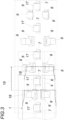
- eine Draufsicht auf den Formkern im Bereich der Formeinrichtung, von der jedoch lediglich die beaufschlagbaren Formstempel in ihrer Verteilung angedeutet sind.
- Die dargestellte Vorrichtung zum Herstellen eines Versteifungsprofils aus üblicherweise mehreren Lagen 1, 2, 3, im Ausführungsbeispiel eine Trägerlage 2 und zwei Decklagen 1 und 3, weist einen die Profilform, z. B. ein Hutprofil, und den Längsverlauf des Profils bestimmenden Formkern 4 auf, an dessen Formflächen die aus vorimprägnierten Faserbahnen geschnittenen Lagen 1, 2, 3 nacheinander formgebend angedrückt werden, und zwar mithilfe einer Formeinrichtung 5. Diese Formeinrichtung 5 umfasst einerseits die Lagen 1, 2, 3 auf einem Auflagebereich 6 des Formkerns 4 festhaltende Niederhalter 7 und anderseits Formstempel 8, die gegenüber den Formflächen des Formkerns 4 ausgerichtet sind und durch Stelltriebe 9 beaufschlagt werden. Die Formstempel 8 sind sowohl in Längsrichtung des Formkerns 4 als auch in dessen Umfangsrichtung gegeneinander versetzt angeordnet, um die Lagen 1, 2, 3 schrittweise nacheinander formgebend an den Formkern 4 bzw. die zuletzt aufgebrachte Lage 1, 2 andrücken zu können. Wegen der weitgehenden Profilsymmetrie sind die Formstempel 8 beidseits des Auflagebereichs 6 paarweise angeordnet. Um ein selbständiges Ausrichten der Formstempel 8 gegenüber den Formflächen des Formkerns 4 zu erreichen, können die Formstempel 8 begrenzt frei verschwenkbar gelagert sein oder eine elastisch nachgiebige Auflage aufweisen.
- Die Stelltriebe 9 sind bevorzugt als mit den Formstempeln 8 eine Baueinheit bildenden Stellzylindern ausgeführt, die um eine in Längsrichtung des Formkerns 4 gebildete Achse 10 verschwenkbar in einem Schlitten 11 gelagert und mittels eines Schwenktriebs 12 schwenkverstellbar sind. Die Schlitten 11 selbst sind auf quer zur Längsrichtung des Formkerns 4 verlaufenden Führungen 13 in einem Gestell 14 verschiebbar geführt und können durch Antriebe 15 entlang der Führungen 13 verstellt werden. Über einen Gelenkkopf 16, beispielsweise eines Manipulators, kann die Formeinrichtung 5 gegenüber dem Längsverlauf des Formkerns 4 ausgerichtet werden, um entweder entlang des ruhenden Formkerns 4 verlagert oder gegenüber dem in Längsrichtung verlagerbaren Formkern 4 ruhend festgehalten zu werden.
- Zur Herstellung eines Versteifungsprofils wird nach der Ausrichtung der Formeinrichtung 5 gegenüber dem Formkern 4 und einer Ausrichtung der Formstempel 8 gegenüber den Formflächen des Formkerns 4 die erste Lage 1 auf den Auflagebereich 6 des Formkerns 4 ausgerichtet aufgelegt und mittels der Niederhalter 7 gegenüber dem Formkern 4 festgehalten, indem die Stelltriebe 17 für die Niederhalter 7 entsprechend angesteuert werden. Wird in dieser Ausgangslage das in Umfangsrichtung des Formkerns 4 an den Auflagebereich 6 anschließende Paar der Formstempel 8 angesteuert, so drücken die durch die Stelltriebe 9 beaufschlagten Formstempel 8 die Lage 1 an den Formkern 4 im Übergangsbereich vom Boden zu den Seitenwänden des Hutprofils an, wobei die Lage 1 aus der in
Fig. 1 strichpunktiert angedeuteten Ausgangslage in einem ersten Verformungsschritt in die um die diesen Übergangsbereich bestimmende Längskante des Formkerns 4 in eine strichliert angedeutete Zwischenlage gebogen wird. - In der
Fig. 3 ist das in die Formeinrichtung 5 eingeführte, im Bereich des ersten Paars der Formstempel 8 befindliche, noch nicht verformte Einlaufende 18 der ersten Lage 1 in vollen Linien dargestellt. Die Verformung des mithilfe der Niederhalter 7 auf dem Auflagebereich 6 festgehaltenen Einlaufendes 18 durch das erste Paar der Formstempel 8 ist strichpunktiert angedeutet. Mit jedem Förderschritt wird der Formkern 4 mit der ersten Lage 1 bei abgehobenen Niederhaltern 7 und Formstempeln 8 um eine Länge verlagert, die kleiner als die in Profillängsrichtung gemessene Länge der Formstempel 8 gewählt wird, um die Lage 1 nach jedem Förderschritt durch das erste Formstempelpaar zu verformen, sodass die Lage 1 im Bereich des durch das erste Formstempelpaar bestimmten Umfangsabschnitts über ihre Länge durchgehend unter einer entsprechenden Druckanwendung in aufeinanderfolgenden Verformungsschritten verformt wird. - Gemäß dem dargestellten Ausführungsbeispiel gelangt das durch das erste Formstempelpaar um die Längskante des Formkerns 4 zwischen dem Boden und den Seitenwänden des Hutprofils gebogene Einlaufende 18 nach drei dem Pfeil 19 entsprechenden Förderschritten in den Bereich des zweiten Paars der Formstempel 8, wie dies in dünnen strichpunktierten Linien dargestellt ist. In dieser Einlaufstellung kann das Einlaufende 18 mithilfe des zweiten Formstempelpaars in einem zweiten Verformungsschritt an die Seitenwände des durch den Formkern 4 bestimmten Hutprofils angedrückt werden, was durch die dickere strichpunktierte Umrissform des Einlaufendes 18 angedeutet ist.
- Aufgrund der gleichmäßigen Abstände der Formstempelpaare voneinander in Profillängsrichtung kommen jeweils nach drei weiteren Förderschritten ein weiteres Paar der Formstempel 8 der über den Umfang des Formkerns 4 versetzt angeordneten Formstempelpaare zum Einsatz, bis mit dem den Formvorgang beendenden letzten Formstempelpaar die erste Lage 1 am Ausgang der Formeinrichtung 5 die durch den Formkern 4 vorgegebene Profilform aufweist.
- Mit jedem weiteren Förderschritt verlängert sich der vollständig geformte Längsabschnitt der ersten Lage 1, bis nach einem vollständigen Durchlauf auf die formbildend an den Formflächen des Formkerns 4 anliegende erste Lage 1 eine zweite Lage 2 in analoger Weise aufgebracht werden kann. Das Lagenaufbringen wird bis zur letzten Lage 3 wiederholt, bevor das geformte Versteifungsprofil vom Formkern 4 gegebenenfalls nach einer zumindest teilweisen Härtung der vorimprägnierten Faserbahnen vom Formkern 4 abgenommen werden kann.
- Aufgrund der mit dem Andrücken der einzelnen Lagen 1, 2, 3 an den Formkern 4 bzw. an die zuletzt aufgebrachte Lage 1, 2 verbundenen Druckbeaufschlagung der Lagen 1, 2, 3 durch die Niederhalter 7 und die Formstempel 8 können die einzelnen Lagen 1, 2, 3 entsprechend den jeweiligen Anforderungen verdichtet werden, wobei über die Anstellung der Stelltriebe 9 bzw. 17 die Dicke der jeweiligen Lagen erfasst werden kann. Um die Verdichtungswirkung zu steigern, können die Niederhalter 7 und die Formstempel 8 durch Schwingungsantriebe beaufschlagt werden.
Claims (7)
- Verfahren zum Herstellen eines Versteifungsprofils aus wenigstens einer aus einer vorimprägnierten Faserbahn geschnittenen Lage (1), die auf einen die Profilform bestimmenden Formkern (4) aufgelegt, im Auflagebereich (6) am Formkern (4) festgehalten und ausgehend von diesem Auflagebereich (6) quer zur Profillängsrichtung fortschreitend bis zu den Profillängsrändern an den Formkern (4) angedrückt wird, wobei die Lage (1) mithilfe von sowohl in Umfangsrichtung als auch in Längsrichtung des Formkerns (4) gegeneinander versetzt angeordneten, in Richtung auf die Formflächen des Formkerns (4) beaufschlagbaren Formstempeln (8) an den Formkern (4) in dessen Längsrichtung schrittweise fortschreitend formgebend angedrückt wird.
- Verfahren nach Anspruch 1, dadurch gekennzeichnet, dass zum Herstellen eines mehrlagigen Versteifungsprofils mit Ausnahme der ersten unmittelbar formgebend an den Formkern (4) angedrückten Lage (1) jede weitere aus einer vorimprägnierten Faserbahn geschnittene Lage (2, 3) in analoger Weise auf die zuvor geformte Lage (1, 2) aufgelegt, im Auflagebereich (6) festgehalten und dann vom Auflagebereich (6) fortschreitend bis zum Profillängsrand mithilfe der sowohl in Umfangsrichtung als auch in Längsrichtung des Formkerns (4) gegeneinander versetzt angeordneten Formstempeln (8) schrittweise an die zuvor geformte Lage (1, 2) formgebend angedrückt wird.
- Vorrichtung zum Herstellen eines Versteifungsprofils aus mehreren aus einer vorimprägnierten Faserbahn geschnittenen Lagen (1, 2, 3) mit einem die Profilform bestimmenden Formkern (4), mit die Lagen (1, 2, 3) auf einem Auflagebereich (6) des Formkerns (4) festhaltenden Niederhaltern (7) und mit einer Formeinrichtung (5) zum formgebenden Andrücken der Lagen (1, 2, 3) an die Formflächen des Formkerns (4), wobei die Formeinrichtung (5) in Richtung auf die Formflächen des Formkerns (4) beaufschlagbare, sowohl in Längsrichtung des Formkerns (4) als auch in dessen Umfangsrichtung gegeneinander versetzt angeordnete Formstempel (8) aufweist und dass die Formeinrichtung (5) und der Formkern (4) relativ gegeneinander in Längsrichtung des Formkerns (4) schrittweise verlagerbar sind.
- Vorrichtung nach Anspruch 3, dadurch gekennzeichnet, dass die Schrittlänge der gegenseitigen relativen Verlagerung der Formeinrichtung (5) und des Formkerns (4) höchstens der in Längsrichtung des Formkerns (4) gemessenen Länge der Formstempel (8) entspricht.
- Vorrichtung nach Anspruch 3 oder 4, dadurch gekennzeichnet, dass die gegebenenfalls auswechselbaren Formstempel (8) je für sich auf einem quer zur Längsrichtung des Formkerns (4) verlagerbaren Schlitten (11) um eine in Längsrichtung des Formkerns (4) verlaufende Achse (10) schwenkbar gelagert sind.
- Vorrichtung nach Anspruch 5, dadurch gekennzeichnet, dass die Formstempel (8) mit Stellzylindern eine auf den Schlitten (11) schwenkbar gelagerte Baueinheit bilden.
- Vorrichtung nach einem der Ansprüche 1 bis 6, dadurch gekennzeichnet, dass die Formeinrichtung (5) die Niederhalter (7) aufweist.
Applications Claiming Priority (2)
| Application Number | Priority Date | Filing Date | Title |
|---|---|---|---|
| ATA50728/2020A AT523380B1 (de) | 2020-08-28 | 2020-08-28 | Verfahren und Vorrichtung zum Herstellen eines Versteifungsprofils |
| PCT/AT2021/060280 WO2022040708A1 (de) | 2020-08-28 | 2021-08-11 | Verfahren und vorrichtung zum herstellen eines versteifungsprofils |
Publications (2)
| Publication Number | Publication Date |
|---|---|
| EP4204204A1 EP4204204A1 (de) | 2023-07-05 |
| EP4204204B1 true EP4204204B1 (de) | 2024-04-03 |
Family
ID=77411356
Family Applications (1)
| Application Number | Title | Priority Date | Filing Date |
|---|---|---|---|
| EP21758585.0A Active EP4204204B1 (de) | 2020-08-28 | 2021-08-11 | Verfahren und vorrichtung zum herstellen eines versteifungsprofils |
Country Status (8)
| Country | Link |
|---|---|
| US (1) | US12269222B2 (de) |
| EP (1) | EP4204204B1 (de) |
| CN (1) | CN115551691B (de) |
| AT (1) | AT523380B1 (de) |
| AU (1) | AU2021334402B2 (de) |
| CA (1) | CA3184295A1 (de) |
| ES (1) | ES2982209T3 (de) |
| WO (1) | WO2022040708A1 (de) |
Families Citing this family (3)
| Publication number | Priority date | Publication date | Assignee | Title |
|---|---|---|---|---|
| JP7676350B2 (ja) * | 2022-12-16 | 2025-05-14 | 三菱重工業株式会社 | 賦形装置および賦形方法 |
| CN116476368A (zh) * | 2023-04-25 | 2023-07-25 | 云阳县锦辉广告有限公司 | 广告灯箱制作用亚克力板折弯装置及其使用方法 |
| CN117301568B (zh) * | 2023-09-26 | 2026-04-14 | 亚普汽车部件股份有限公司 | 一种复合材料预制体成型装置 |
Family Cites Families (20)
| Publication number | Priority date | Publication date | Assignee | Title |
|---|---|---|---|---|
| JPS5120984A (de) * | 1974-08-15 | 1976-02-19 | Mitsubishi Plastics Ind | |
| AT6638U1 (de) * | 2002-10-01 | 2004-01-26 | Gfm Gmbh | Verfahren zum ausschneiden eines zuschnittes aus einer textilen warenbahn zum herstellen von werkstücken aus einem faser-kunststoffverbund |
| JP3782072B2 (ja) * | 2003-05-30 | 2006-06-07 | 川崎重工業株式会社 | 複合材型材の成形方法及び装置 |
| CN101394988B (zh) * | 2006-03-15 | 2010-09-29 | 东丽株式会社 | 预成型体的制造方法及制造装置 |
| JP2008055609A (ja) * | 2006-08-29 | 2008-03-13 | Jamco Corp | 複合材の未硬化連続予備成形方法 |
| JP5082748B2 (ja) * | 2007-10-12 | 2012-11-28 | 富士通株式会社 | コア部材およびコア部材の製造方法 |
| CN101524867B (zh) * | 2009-01-08 | 2010-12-29 | 李苏扬 | 设有连体支撑脚的植物纤维托盘整体压制方法及其专用模具 |
| FR2942741B1 (fr) | 2009-03-05 | 2014-05-16 | Mediterranee Const Ind | Procede et dispositif de fabrication automatisee d'au moins une piece allongee a une ou plusieurs couches en materiaux composites |
| JP4859975B2 (ja) * | 2009-12-24 | 2012-01-25 | 藤倉ゴム工業株式会社 | プリプレグ巻回方法及び装置 |
| GB2502561B (en) * | 2012-05-30 | 2016-03-23 | Gurit Uk Ltd | Press moulding method |
| DE102013109854A1 (de) * | 2013-09-09 | 2015-03-12 | Dieffenbacher GmbH Maschinen- und Anlagenbau | Drapiervorrichtung zum Herstellen eines dreidimensionalen Vorformlings aus Fasermaterial |
| EP2873517B1 (de) | 2013-11-14 | 2019-04-24 | Airbus Defence and Space GmbH | Stabilisierungsvorrichtung, Stabilisierungsverfahren und Verfahren zum erzeugen von Faserverbund-Bauteilen |
| CN103722752B (zh) * | 2013-12-31 | 2016-03-09 | 中国航空工业集团公司北京航空制造工程研究所 | 具有压力检测装置的复合材料预浸带铺放机构 |
| US10399284B2 (en) * | 2014-05-16 | 2019-09-03 | The Boeing Company | Method and apparatus for forming contoured composite laminates |
| US10369740B2 (en) * | 2015-07-09 | 2019-08-06 | The Boeing Company | Method of forming a contoured hat stiffener |
| KR20180068364A (ko) | 2016-12-13 | 2018-06-22 | 현대자동차주식회사 | 섬유 복합재 예비 성형장치 및 이를 이용한 예비 성형체 제조방법 |
| US10717225B2 (en) * | 2017-09-07 | 2020-07-21 | The Boeing Company | Drape forming end effector |
| GB2567699B (en) | 2017-10-23 | 2022-02-09 | Mclaren Automotive Ltd | Moulding arrangement |
| CN107512011A (zh) * | 2017-10-23 | 2017-12-26 | 哈尔滨工业大学 | 一种具有二次加压加热的热塑性复合材料纤维铺放头 |
| ES2734598B2 (es) * | 2018-10-10 | 2020-05-04 | Univ Madrid Politecnica | Máquina de adaptación de una estructura de fibras a un molde para la fabricación de piezas de material compuesto |
-
2020
- 2020-08-28 AT ATA50728/2020A patent/AT523380B1/de not_active IP Right Cessation
-
2021
- 2021-08-11 CN CN202180034347.6A patent/CN115551691B/zh active Active
- 2021-08-11 WO PCT/AT2021/060280 patent/WO2022040708A1/de not_active Ceased
- 2021-08-11 EP EP21758585.0A patent/EP4204204B1/de active Active
- 2021-08-11 US US18/010,010 patent/US12269222B2/en active Active
- 2021-08-11 ES ES21758585T patent/ES2982209T3/es active Active
- 2021-08-11 AU AU2021334402A patent/AU2021334402B2/en active Active
- 2021-08-11 CA CA3184295A patent/CA3184295A1/en active Pending
Also Published As
| Publication number | Publication date |
|---|---|
| CN115551691B (zh) | 2026-04-07 |
| ES2982209T3 (es) | 2024-10-15 |
| CA3184295A1 (en) | 2022-03-03 |
| US20230249414A1 (en) | 2023-08-10 |
| WO2022040708A1 (de) | 2022-03-03 |
| AT523380B1 (de) | 2021-08-15 |
| AU2021334402A1 (en) | 2022-12-22 |
| US12269222B2 (en) | 2025-04-08 |
| BR112022021062A2 (pt) | 2023-03-07 |
| EP4204204A1 (de) | 2023-07-05 |
| AT523380A4 (de) | 2021-08-15 |
| AU2021334402B2 (en) | 2024-03-28 |
| CN115551691A (zh) | 2022-12-30 |
Similar Documents
| Publication | Publication Date | Title |
|---|---|---|
| EP2227379B1 (de) | Verfahren zur herstellung eines faserverbundwerkstoff-vorformlings aus einem laminat mit zumindest zwei prepreg-lagen sowie herstellungsvorrichtung für ein derartiges verfahren | |
| EP2637842B1 (de) | Verfahren und vorrichtung zur herstellung eines dreidimensionalen vorformlings im zuge der herstellung von faserverstärkten formteilen | |
| AT523380B1 (de) | Verfahren und Vorrichtung zum Herstellen eines Versteifungsprofils | |
| EP2637841A1 (de) | Verfahren und vorrichtung zur herstellung eines dreidimensionalen vorformlings im zuge der herstellung von faserverstärkten formteilen | |
| EP2637843A2 (de) | Verfahren, vorrichtung und formschale zur herstellung eines drei-dimensionalen vorformlings im zuge der herstellung von faserverstärkten formteilen | |
| EP2547512A1 (de) | Faserverbundprofilbauteil sowie verfahren und vorrichtung zur kontinuierlichen herstellung | |
| DE3208634A1 (de) | Verfahren und system zur kontinuierlichen herstellung von plattenfoermigen katalysatoren | |
| EP3126131B1 (de) | Verfahren zur umformung eines flachbahnmaterials und vorrichtung | |
| WO2015032982A2 (de) | Drapiervorrichtung zum herstellen eines dreidimensionalen vorformlings aus fasermaterial | |
| DE60217170T2 (de) | Verfahren und vorrichtung zur herstellung gewellter verbundplatten | |
| EP2804730B1 (de) | Verfahren und vorrichtung zur herstellung eines dreidimensionalen vorformlings im zuge der herstellung von faserverstärkten formteilen | |
| DE102011053676A1 (de) | Rohrbiegemaschine | |
| WO2018042006A1 (de) | Verfahren und drapiervorrichtung zur herstellung eines dreidimensionalen vorformlings | |
| DE2620795C2 (de) | ||
| DE102015201264B4 (de) | Verformvorrichtung zum Verformen eines vorimprägnierten Faserverbundhalbzeuges sowie Verfahren zum Verformen eines vorimprägnierten Faserverbundhalbzeuges | |
| DE102020100546A1 (de) | Werkzeug und Verfahren zum Formen eines Bauteils | |
| EP4101627B1 (de) | Klemmvorrichtung für eine reifenbaumaschine sowie verfahren zum einklemmen eines reifenbauteils | |
| CH706902A2 (de) | Verfahren zur Herstellung faserverstärkter Kunststoffplatten und Vorrichtung dazu. | |
| DE1629383C3 (de) | Vorrichtung zum Pressen und Erwärmen eines Bandes, insbesondere eines Treibriemens oder Fördergurtes | |
| DE1914148C3 (de) | Verfahren und Vorrichtung zum Herstellen von Absatzflecken aus warmverformbarem Kunststoff | |
| DE202016104843U1 (de) | Drapiervorrichtung zur Herstellung eines dreidimensionalen Vorformlings | |
| DE102022118559A1 (de) | Verfahren und Werkzeug zur Herstellung eines Faserverbundbauteils | |
| DE102019132851A1 (de) | Verfahren und Anlage zur Herstellung eines Hybrid-Profilbauteils | |
| DE102016211359A1 (de) | Vorrichtung und Verfahren zum Wechseln einer Bespannung einer Papiermaschine | |
| EP0755770A1 (de) | Verfahren zur Herstellung von Formteilen |
Legal Events
| Date | Code | Title | Description |
|---|---|---|---|
| STAA | Information on the status of an ep patent application or granted ep patent |
Free format text: STATUS: UNKNOWN |
|
| STAA | Information on the status of an ep patent application or granted ep patent |
Free format text: STATUS: THE INTERNATIONAL PUBLICATION HAS BEEN MADE |
|
| PUAI | Public reference made under article 153(3) epc to a published international application that has entered the european phase |
Free format text: ORIGINAL CODE: 0009012 |
|
| STAA | Information on the status of an ep patent application or granted ep patent |
Free format text: STATUS: REQUEST FOR EXAMINATION WAS MADE |
|
| 17P | Request for examination filed |
Effective date: 20221013 |
|
| AK | Designated contracting states |
Kind code of ref document: A1 Designated state(s): AL AT BE BG CH CY CZ DE DK EE ES FI FR GB GR HR HU IE IS IT LI LT LU LV MC MK MT NL NO PL PT RO RS SE SI SK SM TR |
|
| P01 | Opt-out of the competence of the unified patent court (upc) registered |
Effective date: 20230712 |
|
| DAV | Request for validation of the european patent (deleted) | ||
| DAX | Request for extension of the european patent (deleted) | ||
| GRAP | Despatch of communication of intention to grant a patent |
Free format text: ORIGINAL CODE: EPIDOSNIGR1 |
|
| STAA | Information on the status of an ep patent application or granted ep patent |
Free format text: STATUS: GRANT OF PATENT IS INTENDED |
|
| INTG | Intention to grant announced |
Effective date: 20240105 |
|
| GRAS | Grant fee paid |
Free format text: ORIGINAL CODE: EPIDOSNIGR3 |
|
| GRAA | (expected) grant |
Free format text: ORIGINAL CODE: 0009210 |
|
| STAA | Information on the status of an ep patent application or granted ep patent |
Free format text: STATUS: THE PATENT HAS BEEN GRANTED |
|
| AK | Designated contracting states |
Kind code of ref document: B1 Designated state(s): AL AT BE BG CH CY CZ DE DK EE ES FI FR GB GR HR HU IE IS IT LI LT LU LV MC MK MT NL NO PL PT RO RS SE SI SK SM TR |
|
| REG | Reference to a national code |
Ref country code: CH Ref legal event code: EP |
|
| REG | Reference to a national code |
Ref country code: IE Ref legal event code: FG4D Free format text: LANGUAGE OF EP DOCUMENT: GERMAN |
|
| REG | Reference to a national code |
Ref country code: DE Ref legal event code: R096 Ref document number: 502021003239 Country of ref document: DE |
|
| REG | Reference to a national code |
Ref country code: DE Ref legal event code: R081 Ref document number: 502021003239 Country of ref document: DE Owner name: GFM GMBH, AT Free format text: FORMER OWNER: GFM - GMBH, STEYR, AT |
|
| REG | Reference to a national code |
Ref country code: LT Ref legal event code: MG9D |
|
| REG | Reference to a national code |
Ref country code: NL Ref legal event code: FP |
|
| PG25 | Lapsed in a contracting state [announced via postgrant information from national office to epo] |
Ref country code: IS Free format text: LAPSE BECAUSE OF FAILURE TO SUBMIT A TRANSLATION OF THE DESCRIPTION OR TO PAY THE FEE WITHIN THE PRESCRIBED TIME-LIMIT Effective date: 20240803 |
|
| PG25 | Lapsed in a contracting state [announced via postgrant information from national office to epo] |
Ref country code: BG Free format text: LAPSE BECAUSE OF FAILURE TO SUBMIT A TRANSLATION OF THE DESCRIPTION OR TO PAY THE FEE WITHIN THE PRESCRIBED TIME-LIMIT Effective date: 20240403 |
|
| PG25 | Lapsed in a contracting state [announced via postgrant information from national office to epo] |
Ref country code: HR Free format text: LAPSE BECAUSE OF FAILURE TO SUBMIT A TRANSLATION OF THE DESCRIPTION OR TO PAY THE FEE WITHIN THE PRESCRIBED TIME-LIMIT Effective date: 20240403 Ref country code: FI Free format text: LAPSE BECAUSE OF FAILURE TO SUBMIT A TRANSLATION OF THE DESCRIPTION OR TO PAY THE FEE WITHIN THE PRESCRIBED TIME-LIMIT Effective date: 20240403 |
|
| PG25 | Lapsed in a contracting state [announced via postgrant information from national office to epo] |
Ref country code: GR Free format text: LAPSE BECAUSE OF FAILURE TO SUBMIT A TRANSLATION OF THE DESCRIPTION OR TO PAY THE FEE WITHIN THE PRESCRIBED TIME-LIMIT Effective date: 20240704 |
|
| PG25 | Lapsed in a contracting state [announced via postgrant information from national office to epo] |
Ref country code: PT Free format text: LAPSE BECAUSE OF FAILURE TO SUBMIT A TRANSLATION OF THE DESCRIPTION OR TO PAY THE FEE WITHIN THE PRESCRIBED TIME-LIMIT Effective date: 20240805 |
|
| REG | Reference to a national code |
Ref country code: ES Ref legal event code: FG2A Ref document number: 2982209 Country of ref document: ES Kind code of ref document: T3 Effective date: 20241015 |
|
| PG25 | Lapsed in a contracting state [announced via postgrant information from national office to epo] |
Ref country code: CZ Free format text: LAPSE BECAUSE OF FAILURE TO SUBMIT A TRANSLATION OF THE DESCRIPTION OR TO PAY THE FEE WITHIN THE PRESCRIBED TIME-LIMIT Effective date: 20240403 |
|
| PG25 | Lapsed in a contracting state [announced via postgrant information from national office to epo] |
Ref country code: PL Free format text: LAPSE BECAUSE OF FAILURE TO SUBMIT A TRANSLATION OF THE DESCRIPTION OR TO PAY THE FEE WITHIN THE PRESCRIBED TIME-LIMIT Effective date: 20240403 |
|
| PG25 | Lapsed in a contracting state [announced via postgrant information from national office to epo] |
Ref country code: LV Free format text: LAPSE BECAUSE OF FAILURE TO SUBMIT A TRANSLATION OF THE DESCRIPTION OR TO PAY THE FEE WITHIN THE PRESCRIBED TIME-LIMIT Effective date: 20240403 |
|
| PG25 | Lapsed in a contracting state [announced via postgrant information from national office to epo] |
Ref country code: PT Free format text: LAPSE BECAUSE OF FAILURE TO SUBMIT A TRANSLATION OF THE DESCRIPTION OR TO PAY THE FEE WITHIN THE PRESCRIBED TIME-LIMIT Effective date: 20240805 Ref country code: PL Free format text: LAPSE BECAUSE OF FAILURE TO SUBMIT A TRANSLATION OF THE DESCRIPTION OR TO PAY THE FEE WITHIN THE PRESCRIBED TIME-LIMIT Effective date: 20240403 Ref country code: NO Free format text: LAPSE BECAUSE OF FAILURE TO SUBMIT A TRANSLATION OF THE DESCRIPTION OR TO PAY THE FEE WITHIN THE PRESCRIBED TIME-LIMIT Effective date: 20240703 Ref country code: LV Free format text: LAPSE BECAUSE OF FAILURE TO SUBMIT A TRANSLATION OF THE DESCRIPTION OR TO PAY THE FEE WITHIN THE PRESCRIBED TIME-LIMIT Effective date: 20240403 Ref country code: IS Free format text: LAPSE BECAUSE OF FAILURE TO SUBMIT A TRANSLATION OF THE DESCRIPTION OR TO PAY THE FEE WITHIN THE PRESCRIBED TIME-LIMIT Effective date: 20240803 Ref country code: HR Free format text: LAPSE BECAUSE OF FAILURE TO SUBMIT A TRANSLATION OF THE DESCRIPTION OR TO PAY THE FEE WITHIN THE PRESCRIBED TIME-LIMIT Effective date: 20240403 Ref country code: GR Free format text: LAPSE BECAUSE OF FAILURE TO SUBMIT A TRANSLATION OF THE DESCRIPTION OR TO PAY THE FEE WITHIN THE PRESCRIBED TIME-LIMIT Effective date: 20240704 Ref country code: FI Free format text: LAPSE BECAUSE OF FAILURE TO SUBMIT A TRANSLATION OF THE DESCRIPTION OR TO PAY THE FEE WITHIN THE PRESCRIBED TIME-LIMIT Effective date: 20240403 Ref country code: CZ Free format text: LAPSE BECAUSE OF FAILURE TO SUBMIT A TRANSLATION OF THE DESCRIPTION OR TO PAY THE FEE WITHIN THE PRESCRIBED TIME-LIMIT Effective date: 20240403 Ref country code: BG Free format text: LAPSE BECAUSE OF FAILURE TO SUBMIT A TRANSLATION OF THE DESCRIPTION OR TO PAY THE FEE WITHIN THE PRESCRIBED TIME-LIMIT Effective date: 20240403 Ref country code: RS Free format text: LAPSE BECAUSE OF FAILURE TO SUBMIT A TRANSLATION OF THE DESCRIPTION OR TO PAY THE FEE WITHIN THE PRESCRIBED TIME-LIMIT Effective date: 20240703 |
|
| REG | Reference to a national code |
Ref country code: DE Ref legal event code: R097 Ref document number: 502021003239 Country of ref document: DE |
|
| PG25 | Lapsed in a contracting state [announced via postgrant information from national office to epo] |
Ref country code: DK Free format text: LAPSE BECAUSE OF FAILURE TO SUBMIT A TRANSLATION OF THE DESCRIPTION OR TO PAY THE FEE WITHIN THE PRESCRIBED TIME-LIMIT Effective date: 20240403 |
|
| PG25 | Lapsed in a contracting state [announced via postgrant information from national office to epo] |
Ref country code: EE Free format text: LAPSE BECAUSE OF FAILURE TO SUBMIT A TRANSLATION OF THE DESCRIPTION OR TO PAY THE FEE WITHIN THE PRESCRIBED TIME-LIMIT Effective date: 20240403 |
|
| PG25 | Lapsed in a contracting state [announced via postgrant information from national office to epo] |
Ref country code: RO Free format text: LAPSE BECAUSE OF FAILURE TO SUBMIT A TRANSLATION OF THE DESCRIPTION OR TO PAY THE FEE WITHIN THE PRESCRIBED TIME-LIMIT Effective date: 20240403 Ref country code: SK Free format text: LAPSE BECAUSE OF FAILURE TO SUBMIT A TRANSLATION OF THE DESCRIPTION OR TO PAY THE FEE WITHIN THE PRESCRIBED TIME-LIMIT Effective date: 20240403 |
|
| PG25 | Lapsed in a contracting state [announced via postgrant information from national office to epo] |
Ref country code: SM Free format text: LAPSE BECAUSE OF FAILURE TO SUBMIT A TRANSLATION OF THE DESCRIPTION OR TO PAY THE FEE WITHIN THE PRESCRIBED TIME-LIMIT Effective date: 20240403 |
|
| PG25 | Lapsed in a contracting state [announced via postgrant information from national office to epo] |
Ref country code: SM Free format text: LAPSE BECAUSE OF FAILURE TO SUBMIT A TRANSLATION OF THE DESCRIPTION OR TO PAY THE FEE WITHIN THE PRESCRIBED TIME-LIMIT Effective date: 20240403 Ref country code: SK Free format text: LAPSE BECAUSE OF FAILURE TO SUBMIT A TRANSLATION OF THE DESCRIPTION OR TO PAY THE FEE WITHIN THE PRESCRIBED TIME-LIMIT Effective date: 20240403 Ref country code: RO Free format text: LAPSE BECAUSE OF FAILURE TO SUBMIT A TRANSLATION OF THE DESCRIPTION OR TO PAY THE FEE WITHIN THE PRESCRIBED TIME-LIMIT Effective date: 20240403 Ref country code: EE Free format text: LAPSE BECAUSE OF FAILURE TO SUBMIT A TRANSLATION OF THE DESCRIPTION OR TO PAY THE FEE WITHIN THE PRESCRIBED TIME-LIMIT Effective date: 20240403 Ref country code: DK Free format text: LAPSE BECAUSE OF FAILURE TO SUBMIT A TRANSLATION OF THE DESCRIPTION OR TO PAY THE FEE WITHIN THE PRESCRIBED TIME-LIMIT Effective date: 20240403 |
|
| PLBE | No opposition filed within time limit |
Free format text: ORIGINAL CODE: 0009261 |
|
| STAA | Information on the status of an ep patent application or granted ep patent |
Free format text: STATUS: NO OPPOSITION FILED WITHIN TIME LIMIT |
|
| 26N | No opposition filed |
Effective date: 20250106 |
|
| REG | Reference to a national code |
Ref country code: CH Ref legal event code: PL |
|
| PG25 | Lapsed in a contracting state [announced via postgrant information from national office to epo] |
Ref country code: LU Free format text: LAPSE BECAUSE OF NON-PAYMENT OF DUE FEES Effective date: 20240811 |
|
| PG25 | Lapsed in a contracting state [announced via postgrant information from national office to epo] |
Ref country code: SI Free format text: LAPSE BECAUSE OF FAILURE TO SUBMIT A TRANSLATION OF THE DESCRIPTION OR TO PAY THE FEE WITHIN THE PRESCRIBED TIME-LIMIT Effective date: 20240403 Ref country code: MC Free format text: LAPSE BECAUSE OF FAILURE TO SUBMIT A TRANSLATION OF THE DESCRIPTION OR TO PAY THE FEE WITHIN THE PRESCRIBED TIME-LIMIT Effective date: 20240403 Ref country code: CH Free format text: LAPSE BECAUSE OF NON-PAYMENT OF DUE FEES Effective date: 20240831 |
|
| PG25 | Lapsed in a contracting state [announced via postgrant information from national office to epo] |
Ref country code: IE Free format text: LAPSE BECAUSE OF NON-PAYMENT OF DUE FEES Effective date: 20240811 |
|
| PG25 | Lapsed in a contracting state [announced via postgrant information from national office to epo] |
Ref country code: SE Free format text: LAPSE BECAUSE OF FAILURE TO SUBMIT A TRANSLATION OF THE DESCRIPTION OR TO PAY THE FEE WITHIN THE PRESCRIBED TIME-LIMIT Effective date: 20240403 |
|
| PGFP | Annual fee paid to national office [announced via postgrant information from national office to epo] |
Ref country code: NL Payment date: 20250825 Year of fee payment: 5 |
|
| PGFP | Annual fee paid to national office [announced via postgrant information from national office to epo] |
Ref country code: ES Payment date: 20250916 Year of fee payment: 5 |
|
| PGFP | Annual fee paid to national office [announced via postgrant information from national office to epo] |
Ref country code: DE Payment date: 20250805 Year of fee payment: 5 |
|
| PGFP | Annual fee paid to national office [announced via postgrant information from national office to epo] |
Ref country code: BE Payment date: 20250825 Year of fee payment: 5 Ref country code: GB Payment date: 20250804 Year of fee payment: 5 |
|
| PGFP | Annual fee paid to national office [announced via postgrant information from national office to epo] |
Ref country code: FR Payment date: 20250825 Year of fee payment: 5 Ref country code: AT Payment date: 20251020 Year of fee payment: 5 |
|
| PG25 | Lapsed in a contracting state [announced via postgrant information from national office to epo] |
Ref country code: IT Free format text: LAPSE BECAUSE OF NON-PAYMENT OF DUE FEES Effective date: 20240811 |
|
| PG25 | Lapsed in a contracting state [announced via postgrant information from national office to epo] |
Ref country code: CY Free format text: LAPSE BECAUSE OF FAILURE TO SUBMIT A TRANSLATION OF THE DESCRIPTION OR TO PAY THE FEE WITHIN THE PRESCRIBED TIME-LIMIT; INVALID AB INITIO Effective date: 20210811 |
|
| PG25 | Lapsed in a contracting state [announced via postgrant information from national office to epo] |
Ref country code: HU Free format text: LAPSE BECAUSE OF FAILURE TO SUBMIT A TRANSLATION OF THE DESCRIPTION OR TO PAY THE FEE WITHIN THE PRESCRIBED TIME-LIMIT; INVALID AB INITIO Effective date: 20210811 |
|
| PG25 | Lapsed in a contracting state [announced via postgrant information from national office to epo] |
Ref country code: IT Free format text: LAPSE BECAUSE OF NON-PAYMENT OF DUE FEES Effective date: 20240811 |
|
| PGFP | Annual fee paid to national office [announced via postgrant information from national office to epo] |
Ref country code: IT Payment date: 20250825 Year of fee payment: 5 |
|
| PGRI | Patent reinstated in contracting state [announced from national office to epo] |
Ref country code: IT Effective date: 20240831 |