EP4203788B1 - Continuous glucose sensor and mounting assembly - Google Patents
Continuous glucose sensor and mounting assembly Download PDFInfo
- Publication number
- EP4203788B1 EP4203788B1 EP21794016.2A EP21794016A EP4203788B1 EP 4203788 B1 EP4203788 B1 EP 4203788B1 EP 21794016 A EP21794016 A EP 21794016A EP 4203788 B1 EP4203788 B1 EP 4203788B1
- Authority
- EP
- European Patent Office
- Prior art keywords
- sensor
- probe
- introducer
- compartment
- sensor probe
- Prior art date
- Legal status (The legal status is an assumption and is not a legal conclusion. Google has not performed a legal analysis and makes no representation as to the accuracy of the status listed.)
- Active
Links
Images







Classifications
-
- A—HUMAN NECESSITIES
- A61—MEDICAL OR VETERINARY SCIENCE; HYGIENE
- A61B—DIAGNOSIS; SURGERY; IDENTIFICATION
- A61B5/00—Measuring for diagnostic purposes; Identification of persons
- A61B5/145—Measuring characteristics of blood in vivo, e.g. gas concentration or pH-value ; Measuring characteristics of body fluids or tissues, e.g. interstitial fluid or cerebral tissue
- A61B5/14532—Measuring characteristics of blood in vivo, e.g. gas concentration or pH-value ; Measuring characteristics of body fluids or tissues, e.g. interstitial fluid or cerebral tissue for measuring glucose, e.g. by tissue impedance measurement
-
- A—HUMAN NECESSITIES
- A61—MEDICAL OR VETERINARY SCIENCE; HYGIENE
- A61B—DIAGNOSIS; SURGERY; IDENTIFICATION
- A61B5/00—Measuring for diagnostic purposes; Identification of persons
- A61B5/145—Measuring characteristics of blood in vivo, e.g. gas concentration or pH-value ; Measuring characteristics of body fluids or tissues, e.g. interstitial fluid or cerebral tissue
- A61B5/1468—Measuring characteristics of blood in vivo, e.g. gas concentration or pH-value ; Measuring characteristics of body fluids or tissues, e.g. interstitial fluid or cerebral tissue using chemical or electrochemical methods, e.g. by polarographic means
- A61B5/1486—Measuring characteristics of blood in vivo, e.g. gas concentration or pH-value ; Measuring characteristics of body fluids or tissues, e.g. interstitial fluid or cerebral tissue using chemical or electrochemical methods, e.g. by polarographic means using enzyme electrodes, e.g. with immobilised oxidase
- A61B5/14865—Measuring characteristics of blood in vivo, e.g. gas concentration or pH-value ; Measuring characteristics of body fluids or tissues, e.g. interstitial fluid or cerebral tissue using chemical or electrochemical methods, e.g. by polarographic means using enzyme electrodes, e.g. with immobilised oxidase invasive, e.g. introduced into the body by a catheter or needle or using implanted sensors
-
- A—HUMAN NECESSITIES
- A61—MEDICAL OR VETERINARY SCIENCE; HYGIENE
- A61B—DIAGNOSIS; SURGERY; IDENTIFICATION
- A61B5/00—Measuring for diagnostic purposes; Identification of persons
- A61B5/145—Measuring characteristics of blood in vivo, e.g. gas concentration or pH-value ; Measuring characteristics of body fluids or tissues, e.g. interstitial fluid or cerebral tissue
- A61B5/1495—Calibrating or testing of in-vivo probes
-
- A—HUMAN NECESSITIES
- A61—MEDICAL OR VETERINARY SCIENCE; HYGIENE
- A61B—DIAGNOSIS; SURGERY; IDENTIFICATION
- A61B5/00—Measuring for diagnostic purposes; Identification of persons
- A61B5/68—Arrangements of detecting, measuring or recording means, e.g. sensors, in relation to patient
- A61B5/6846—Arrangements of detecting, measuring or recording means, e.g. sensors, in relation to patient specially adapted to be brought in contact with an internal body part, i.e. invasive
- A61B5/6847—Arrangements of detecting, measuring or recording means, e.g. sensors, in relation to patient specially adapted to be brought in contact with an internal body part, i.e. invasive mounted on an invasive device
- A61B5/6848—Needles
- A61B5/6849—Needles in combination with a needle set
-
- G—PHYSICS
- G01—MEASURING; TESTING
- G01N—INVESTIGATING OR ANALYSING MATERIALS BY DETERMINING THEIR CHEMICAL OR PHYSICAL PROPERTIES
- G01N27/00—Investigating or analysing materials by the use of electric, electrochemical, or magnetic means
- G01N27/26—Investigating or analysing materials by the use of electric, electrochemical, or magnetic means by investigating electrochemical variables; by using electrolysis or electrophoresis
- G01N27/416—Systems
- G01N27/4163—Systems checking the operation of, or calibrating, the measuring apparatus
-
- A—HUMAN NECESSITIES
- A61—MEDICAL OR VETERINARY SCIENCE; HYGIENE
- A61B—DIAGNOSIS; SURGERY; IDENTIFICATION
- A61B2560/00—Constructional details of operational features of apparatus; Accessories for medical measuring apparatus
- A61B2560/02—Operational features
- A61B2560/0266—Operational features for monitoring or limiting apparatus function
- A61B2560/028—Arrangements to prevent overuse, e.g. by counting the number of uses
- A61B2560/0285—Apparatus for single use
-
- A—HUMAN NECESSITIES
- A61—MEDICAL OR VETERINARY SCIENCE; HYGIENE
- A61B—DIAGNOSIS; SURGERY; IDENTIFICATION
- A61B2560/00—Constructional details of operational features of apparatus; Accessories for medical measuring apparatus
- A61B2560/06—Accessories for medical measuring apparatus
- A61B2560/063—Devices specially adapted for delivering implantable medical measuring apparatus
-
- A—HUMAN NECESSITIES
- A61—MEDICAL OR VETERINARY SCIENCE; HYGIENE
- A61B—DIAGNOSIS; SURGERY; IDENTIFICATION
- A61B2562/00—Details of sensors; Constructional details of sensor housings or probes; Accessories for sensors
- A61B2562/12—Manufacturing methods specially adapted for producing sensors for in-vivo measurements
-
- A—HUMAN NECESSITIES
- A61—MEDICAL OR VETERINARY SCIENCE; HYGIENE
- A61B—DIAGNOSIS; SURGERY; IDENTIFICATION
- A61B2562/00—Details of sensors; Constructional details of sensor housings or probes; Accessories for sensors
- A61B2562/12—Manufacturing methods specially adapted for producing sensors for in-vivo measurements
- A61B2562/125—Manufacturing methods specially adapted for producing sensors for in-vivo measurements characterised by the manufacture of electrodes
-
- A—HUMAN NECESSITIES
- A61—MEDICAL OR VETERINARY SCIENCE; HYGIENE
- A61B—DIAGNOSIS; SURGERY; IDENTIFICATION
- A61B2562/00—Details of sensors; Constructional details of sensor housings or probes; Accessories for sensors
- A61B2562/16—Details of sensor housings or probes; Details of structural supports for sensors
- A61B2562/166—Details of sensor housings or probes; Details of structural supports for sensors the sensor is mounted on a specially adapted printed circuit board
-
- A—HUMAN NECESSITIES
- A61—MEDICAL OR VETERINARY SCIENCE; HYGIENE
- A61B—DIAGNOSIS; SURGERY; IDENTIFICATION
- A61B2562/00—Details of sensors; Constructional details of sensor housings or probes; Accessories for sensors
- A61B2562/24—Hygienic packaging for medical sensors; Maintaining apparatus for sensor hygiene
- A61B2562/242—Packaging, i.e. for packaging the sensor or apparatus before use
Definitions
- the present disclosure is to systems for continuous monitoring of glucose in a patient.
- Continuous glucose monitoring is important to individuals with diabetes, as they must determine when insulin is needed to reduce glucose levels or when additional glucose is needed to raise the level of glucose.
- a continuous glucose monitoring device usually adheres to a patient's skin and transmits glucose reading to a remote monitoring device.
- the CGM can be incorporated in a closed loop system (artificial pancreas) in which, an insulin pump automatically administers and adjusts insulin delivery according to CGM transmitted glucose readings (closed loop system).
- Glucose monitoring systems according to the state of the art are for instance described in US2013/0150691A1 , US2018/0325433A1 and US2012/0323098A1 .
- a fully disposable sensing device for continuous monitoring of glucose.
- a planar sensor probe having a minimal surface area and maximal electrodes surface area.
- a mounting device which is easy to use, minimizes pain, and minimizes insertion trauma.
- a mounting device that is fully automatic in which insertion and retraction of introducer sharp is done by a button press with no patient's intervention in spring pre-loading.
- a one piece, disposable mounting device that is pre-assembled in the factory and includes the sterilized sensor probe and the non-sterilized components and thus, reducing mounting steps at each device replacement.
- a one piece disposable mounting device that is cheap for production in which the relatively expensive spring loaded mechanism is not sterilized.
- the disclosure presents a fully disposable, one piece continuous glucose monitoring (CGM) device (sensing device), which includes a sensor and a sensor probe, and a fully disposable, one piece, mounting assembly/unit for mounting the CGM device (mounting assembly, both mounting unit and mounting assembly used interchangeably).
- CGM continuous glucose monitoring
- the device and the mounting unit are pre-assembled in the factory to a one piece, disposable, mounting assembly.
- the mounting assembly is comprised of sealed compartment that includes a portion of the sensor and a non-sealed compartment that includes another portion of the sensor.
- the mounting assembly can be partially, and preferably, fully automatic, at a button press - the sensor is adhered to the skin, and the sensor probe is inserted into the subcutaneous tissue.
- the sensor probe in some embodiments, includes a first portion which is inserted in the subcutaneous tissue and a second portion adapted to be received in a sensor housing (together the sensor probe, the glucose sensor, and sensor housing comprising a sensing device, as noted above).
- the sensor housing includes an upper cover and a lower cover, the lower cover including an adhesive, in some embodiments, for adhering the sensor to the skin.
- the sensing device i.e., the sensor housing and sensor probe
- the sensing device is removed from the body and disposed.
- the senor comprises an electronic printed circuit board assembly ("PCBA” or “electronics”) and may also include a variety of optional components, such as, for example, a receiver, a transmitter, a processing circuit, a battery, an alarm system, and/or a data storage unit.
- the sensor includes a plurality of conductive contacts, e.g., two or more conductive contacts (e.g., conductive springs), that can be configured for coupling to two or more respective contact pads on the sensor probe.
- the sensor probe in some embodiments, includes at least one working electrode, a counter electrode, at least two (2) electrical conductors, and at least two (2) contact pads.
- the probe is planar and includes two (2) electrodes - a working electrode which can be positioned on one side of the probe, in some embodiments, at the distal end of the probe, and a counter electrode positioned, in some embodiments, on the opposite side. Both electrodes, in some embodiments, are connected with electrical conductors to contact pads that can be positioned on both sides of a contact(s) plate(s).
- the contact plate in some embodiments, is perpendicular to the probe (and in some embodiments, can be a part of the probe) and can reside within the sensor housing such that at least one (1) contact pad is facing the PCBA, and another (e.g., the other) contact pad is facing the opposite direction.
- the contacts plate is folded on one (1) side at 180 degrees such that both contact pads are facing the PCBA and thus, simplifying electrical connection.
- the probe and the contact(s) plate(s) are made from a single matrix sheet (e.g. polyimide) folded such that the probe is configured to be perpendicular to the skin, the contacts plate is perpendicular to the probe (parallel to skin), and both contact pads are facing the PCBA.
- a mounting unit is provided and configured for mounting the sensing device (e.g., see above embodiments) onto a patient.
- the mounting unit can be pre-assembled with the sensing device such that the mounting unit and the sensing device (which includes the sensor and the sensor probe) are provided in one piece (mounting assembly) that is packed in one box.
- the mounting unit in some embodiments, is comprised of two compartments having two pre-assembled housings, a non-sealed, non-sterilized compartment (spring compartment) that includes the insertion and retraction mechanisms and a portion of the sensing device, and a sealed, sterilized compartment (probe compartment) that includes the sensor probe.
- Both compartments have housings, a spring compartment housing and a probe compartment housing, that are rigidly pre-assembled during manufacture (for example), the spring compartment housing on top of the probe compartment housing.
- the probe compartment is preferably sealed and sterilized with radiation (e.g., gamma or e-beam).
- radiation e.g., gamma or e-beam.
- the patient removes a protecting lid from the bottom side of the sensor probe housing and adheres the mounting assembly to the skin.
- the sensor and sensor probe are displaced within the sensor probe housing and mounted onto the patient (with the probe being inserted into tissue).
- the introducer for insertion of the sensor probe into the subcutaneous tissue.
- the introducer in some embodiments, includes a sharp tip at one end which is configured to penetrate the skin, and an introducer cap, at the other end, which is configured to drive the introducer in one direction during insertion and the opposite direction during retraction.
- the introducer in some embodiments, is positioned within the mounting assembly and spans the non-sterilized compartment, the sterilized compartment, and an elastomeric septum (that provides sealing to the sealed, sterilized probe compartment). The introducer can be displaced through the septum in one direction during sensor probe insertion, and then, in an opposite direction during introducer retraction. Following device mounting, the mounting unit can be removed from the body leaving the sensor on the skin and the sensor probe within the subcutaneous tissue.
- the mounting unit after triggering, operation of the mounting unit is automatic. For example, upon pressing an operating button, the mounting unit adheres the sensor to the patient's skin, inserts the sensor probe into the subcutaneous tissue (mounting phase one) and retracts the sensor probe introducer while the sensor probe remains within the body (mounting phase two). After device mounting, the mounting unit can be removed from the body and disposed.
- the mounting unit includes a spring loaded driving mechanism for mounting the device onto the patient, and a spring loaded retraction mechanism for removing the introducer while leaving the sensor on the patient. Upon pressing an operating button, a trigger releases a pre-loaded insertion spring that drives the device (including the sensor, sensor probe, and introducer) in a first direction.
- the introducer is a rigid planar structure having a sharp tip and adapted to support the sensor probe during insertion.
- the introducer and sensor probe can concomitantly be inserted into the subcutaneous tissue; however, in some embodiments, at the end of movement of the introducer at first direction, the sensor probe is further advanced (e.g., for additional 1-3mm) in the same first direction.
- local trauma within the surrounding tissue can be minimized because the cross profile of the sensor probe is very low (e.g., causes minimal trauma) and the glucose sensing electrode (i.e., the working electrode), that is located at the distal end of the probe, is exposed to a minimal local inflammatory reaction.
- An assembly process for the device includes the following steps (which in some examples are consecutive steps):
- a method of mounting the device includes the following steps (in some examples, consecutive steps): removal of the protecting lid, placement of mounting assembly on the skin, button press, and removal of mounting unit.
- a continuous glucose monitoring system for continuously monitoring glucose levels of a user.
- the system includes a mounting assembly, and a sensing device, where at least a portion of the sensing device is housed within the mounting assembly prior to mounting the sensing device on the user.
- an assembly method for assembling a mounting assembly and a sensing device for a continuous glucose monitoring system includes assembling a/the sensing device and assembling a/the mounting assembly.
- the method includes at least one of, and preferably a plurality of, and most preferably all of:
- the method includes at least one of, and preferable a plurality of, and most preferably all of:
- Such examples, 2. may also include one and/or another of the following additional features, functionality, structure, steps, or clarifications, yielding yet further embodiments (as is clear from the listing, some of the additional features, functionality, structure, steps, and clarifications - as may be the case - build off of, and/or are based on, previously/earlier recited additional features, functionality, structure, steps, or clarifications):
- FIG. 1 shows a scheme of a continuous-glucose-monitoring (CGM) system, according to some embodiments, that includes an implantable subcutaneous glucose sensitive probe for detecting glucose levels in the interstitial fluid of a patient.
- the CGM system in some embodiments, includes a disposable mounting assembly 1 and a durable remote display unit 2.
- Remote display unit 2 in some embodiments, has a receiver for receiving glucose readings from a skin adhered glucose sensor ("sensor” or "glucose sensor” 50), and may also include a screen for presenting the received glucose readings.
- Mounting assembly 1 is a one-piece, disposable unit that includes sensor 50 and a mounting unit 10 for mounting sensor 50 onto a patient.
- Mounting unit 10 and sensor 50 are pre-assembled during manufacture, and thus, are provided in one single disposable unit - mounting assembly 1.
- sensor 50 Before sensor mounting (on the body), sensor 50, in some embodiments, at least a portion of the sensor is concealed, and in some embodiments, substantially all or all of the sensor is concealed, within the mounting unit 10.
- Mounting assembly 1 is comprised of two (2) compartments: a non-sterilized, non-sealed compartment, which may also be referred to as a first or spring compartment 9, and a second, sterilized, sealed compartment, which may also be referred to as a probe compartment 6.
- the sensor comprises at least two (2) components that can be pre-assembled during manufacture: a sensor control unit, which in some embodiments, includes a housing adapted for placement on the skin, and a sensor probe 60 that has a first portion configured for insertion in the subcutaneous tissue and a second portion configured for being received in a sensor housing.
- Sensor probe 60 in some embodiments, includes a glucose sensitive enzyme configured for detecting glucose levels in the interstitial fluid within the subcutaneous tissue.
- Sensor 50 is positioned within mounting assembly 10 such that at least a first portion of sensor 50 can be received in the sealed, sterilized compartment (second/probe compartment 6), and at least another portion (e.g., second portion) of sensor 50, which includes a PCBA 53, which is adopted to be received in the non-sealed, non-sterilized compartment (spring compartment 9).
- both compartments of mounting assembly 1 are sterilized.
- second/probe compartment 6 is sterilized with, for example, an e-beam or gamma radiation
- spring compartment 9 is sterilized with a gas (e.g., ethylene oxide).
- the portion of sensor 50 which includes PCBA 53 is configured to be received in a sterilized compartment (spring compartment 9).
- An introducer 20 is included, which is configured for inserting sensor probe 60 into subcutaneous tissue.
- Introducer 20 in such embodiments, may be positioned within mounting assembly 1, and can span non-sterilized spring compartment 9, sterilized probe compartment 6, and an elastomeric septum 52.
- Probe compartment 6 can include a housing 16, a removable lid 17, a portion of sensor 50, and a portion of introducer 20. Sealing can be provided by a protecting lid seal 174, probe compartment seal 162, and septum 52.
- the spring compartment in some embodiments, includes a housing 19, a portion of introducer 20, and spring mechanisms (not shown) for driving introducer 20 in a first direction (e.g., probe 60 insertion), and a second direction, opposite to the first direction (e.g., introducer 20 retraction).
- a patient before use, a patient removes protecting lid 17 providing a free forward movement (e.g., in Figure 1 - downward movement) of sensor 50 and sensor probe 60 within probe compartment housing 16.
- Figures 2A-C show cross-sectional (2A) , spatial (2B) , and oblique cross-sectional (2C) views of mounting assembly 1 that, in some embodiments, is comprised of mounting unit 10 and sensor 50.
- Figure 2A shows mounting unit 10 that can be comprised of probe compartment 6 and spring compartment 9.
- Probe compartment 6, spring compartment 9, and sensor 50 in some embodiments, can be pre-assembled during manufacture, forming mounting assembly 1.
- the probe compartment can include probe compartment housing 16, removable protecting lid 17, a portion of sensor 50, sensor probe (not shown), and at least a portion of introducer 20. Sealing of probe compartment 6 can be provided by protecting lid seal 174, probe compartment seal 162, and septum 52.
- Spring compartment 9 can include a spring compartment housing 19, a portion of introducer 20 including introducer cap 21, and one or more spring mechanisms (e.g., insertion and retraction spring loaded mechanisms).
- the spring mechanisms include at least a plurality of (and in some embodiments, all of) an operating button 11, a trigger 12, trigger latches 18, a sleeve 13, hammer 14, insertion spring 31, retraction spring 32, and retraction spring latch 155. Accordingly, following a press of operating button 11, trigger 12 releases hammer 14, insertion spring 31 drives hammer 14 in a first direction (e.g., forward) which drives introducer cap 21, introducer 20, and sensor 50 in the same direction.
- a first direction e.g., forward
- introducer cap 21 When introducer cap 21 reaches the end of the forward movement (e.g., end of a first mounting phase), in some embodiments, it releases retraction spring latch 155 and retraction spring 32 drives introducer cap 21 and introducer 20 in a second direction, opposite to the first direction (e.g., backward) direction.
- first direction e.g., backward
- Figure 2B shows a spatial view of one-piece mounting unit 10, including probe compartment 6, probe compartment housing 16, spring compartment 9, spring compartment housing 19, and operating button 11.
- Figure 2C shows an oblique cross-sectional view of mounting assembly 1, according to some embodiments, that includes probe compartment housing 16, spring compartment housing 19, sensor 50, sensor probe 60, and introducer 20.
- Removable protecting lid 17 can include a protecting lid base 173, and can be connected to probe compartment housing 16 with a protecting lid thread 172.
- protecting lid supporting ribs 171 provide support to the probe compartment and sensor probe protection.
- Introducer 20 can be connected at one end (e.g., proximal end) to an introducer cap 21, that, in some embodiments, is comprised of introducer cap snap 211, introducer cap snap holder 212, and introducer knob 213.
- the insertion mechanism includes operating button 11, trigger 12, sleeve 13, hammer 14, and insertion spring 31.
- the hammer 14 can include the introducer pulling lever 141, and sensor pushing lever 142 (e.g., three (3) levers).
- the release mechanism includes retraction spring 32 and retraction spring latch 155.
- trigger 12 releases the hammer 14 and insertion spring 31 drives hammer 14 in a (first) forward direction within sleeve 13.
- hammer introducer pulling lever 141 that is connected to introducer cap snap 211, drives introducer 20 in the (first) forward direction, and concomitantly (in some embodiments), the hammer sensor pushing levers 142 drive sensor 50 and sensor probe 60 also in the (first) forward direction.
- introducer cap knob 213 releases retraction spring 32 which drives introducer cap 21 in an opposite (second), e.g., backward, direction.
- Figures 3A-B show exploded (3A) and cross-sectional (3B) views of the sealed, sterilized, probe compartment 6, according to some embodiments.
- Figure 3A shows parts of probe compartment 6 (stacked, e.g., from the bottom up): protecting removable lid 17, protecting lid seal 174, probe compartment seal 162, probe compartment housing 16, sensor housing lower cover 55 and adhesive 56, introducer 20, sensor base plate 54 (not shown), base plate seal 546, sensor probe 60, and contacts plate 61.
- Protecting lid seal 174 and probe compartment seal 174 can be included so as to provide sealing to the probe compartment 6 before mounting the sensor 50 to a patient's body.
- Sensor base plate seal 546 can be included to provide sealing to the sensor after sensor mounting while the sensor is adhered to the patient's skin.
- Figure 3B shows a cross-sectional view of an assembled probe compartment 6: sensor probe housing 16, introducer 20, and protective lid 17 (shown).
- FIG. 4 shows a cross-sectional view of mounting assembly 1 after removal of protecting lid 17 (before sensor mounting), according to some embodiments.
- mounting assembly 1 can include spring compartment housing 19, sensor probe housing 16, insertion spring 31, retraction spring 32, and introducer cap knob 213.
- Protecting lid 17, can include protecting lid base 173, protecting lid thread 172, and protecting lid ribs 171.
- the protecting lid 17, in some embodiments, is removed by the patient by unscrewing the thread 172 from the probe compartment housing worm 161.
- FIG. 5 shows a cross-sectional view of mounting assembly 1 at the end of hammer 14 forward (first direction) movement (end of the first mounting phase).
- sensor 50 is adhered to the skin 80 with adhesive 56 and introducer 20 and sensor probe (not shown) are inserted within the subcutaneous tissue 70.
- Mounting assembly 1, in such embodiments, can include a plurality of, and in some embodiments, all of, spring compartment housing 19, probe compartment housing 16, operating button 11, trigger 12, trigger latches 18, sleeve 13, hammer 14, hammer sensor pushing levers 142, insertion spring 31, retraction spring 32, introducer 20, and introducer knob 213.
- introducer knob 213 is positioned within the loaded retraction spring 32, sensor 50 is adhered to the skin 80, and introducer 20 and sensor probe 60 are inserted within the subcutaneous tissue 70.
- Figure 6 shows a cross-sectional view of the mounting assembly at the end of introducer 20 retraction (end of a second mounting phase).
- the mounting assembly in some embodiments, can include a plurality of, and in some embodiments, all of, probe compartment housing 16, spring compartment housing 19, operating button 11, trigger 12, sleeve 13, hammer 14, hammer introducer pulling lever 141, hammer sensor pushing levers 142, insertion spring 31, retraction spring 32, introducer 20, introducer cap 21, and introducer knob 213.
- sensor 50 is adhered to skin (not shown) and sensor probe 60 is inserted within the subcutaneous tissue (not shown).
- introducer 20 is concealed within mounting assembly 1.
- FIGS 7A-B show spatial (7A) and cross-sectional (7B) views of mounting assembly 1 after removal from the body, sensor 50, in some embodiments, is mounted on the skin (not shown) and sensor probe 60 is inserted in the subcutaneous tissue (not shown).
- Mounting assembly 1 includes probe compartment housing 16, spring compartment housing 19, operating button 11, and introducer 20.
- Figures 8A-B show spatial (8A) and cross-sectional (8B) views of sensor 50, according to some embodiments.
- Figure 8A shows sensor 50 and sensor probe 60, with sensor 50 including, in some embodiments, sensor housing upper cover 51, sensor housing lower cover 55, septum 52, and adhesive 56.
- Figure 8B shows the sensor housing upper cover 51, sensor housing lower cover 55, PCBA 53, septum 52, and adhesive 56.
- the sensor housing lower cover 55, sensor base plate 54 (not shown), septum 52, and adhesive 56 can be configured to be received in the sterilized compartment (e.g., probe compartment 6), and PCBA 53 and sensor housing upper cover 51 are configured to be received in the non-sterilized compartment (e.g., spring compartment 9).
- Figure 8C shows a cross section view of the sensor 50 on a patient skin, the sensor probe 60 is inserted within the subcutaneous tissue.
- the sensor 50 includes the sensor housing upper cover 51, sensor housing lower cover 55, septum 52, and adhesive 56.
- Figure 9 shows the spring release mechanisms, according to some embodiments.
- Figure 9A shows a cross-sectional view (cross-section plan is 45° rotated vs. Figure 2 cross section plan) of the spring release mechanisms.
- Figures 9B and 9C are magnified views of the release mechanisms of insertion spring 31 (9B) and retraction spring 32 (9C) , respectively.
- Figure 9A shows mounting assembly 1 that includes at least a plurality of, and in some embodiments, all of: spring compartment housing 19, operating button 11, trigger 12, sleeve 13, hammer 14, insertion spring 31, retraction spring 32, introducer 20, introducer cap snap 211, and introducer cap knob 213.
- hammer 14 is displaced in a forward (e.g., first) direction by loaded spring 31.
- the introducer cap snap 211 is displaced by hammer 14 in the same (forward/first) direction and concomitantly drives introducer 20 and introducer cap knob 213 in the same (forward/first) direction.
- Figure 9B shows the release mechanism of insertion spring 31, according to some embodiments, where upon pressing operating button 11, the trigger 12 is displaced in the same (forward/first) direction and rotates (in some embodiments, slightly, e.g., less than one rotation) such that hammer 14 is released and displaced (e.g., forward) within sleeve 13 by loaded spring 31.
- Figure 9C shows the retraction mechanism of retraction spring 32, according to some embodiments.
- retraction spring latch 155 is laterally displaced by the introducer cap knob 213, and releases the retraction spring 32.
- Retraction spring 32 is then displaces the introducer 20 in a second/backward direction opposite to the first/forward direction.
- Figure 10 shows an exploded view of parts/components of sensor 50 and sensor probe 60, according to some embodiments.
- Sensor 50 and sensor probe 60 can include (in a stacked arrangement, e.g., stacking bottom-up) at least a plurality of, and in some embodiments, all of: adhesive 56, sensor housing lower cover 55, sensor probe 60, contacts plate 61, sensor base plate 54, PCBA 53, septum 52, and sensor housing upper cover 51.
- the adhesive 56, sensor housing lower cover 55, sensor base plate 54, sensor probe 60, contacts plate 61, septum 52 and a portion of introducer 20 are sterilized (according to some embodiments); PCBA 53 and sensor housing upper cover 51 are not sterilized (according to some embodiments).
- Figure 11 shows sensor 50 components, according to some embodiments.
- Figure 11A shows a top level view of sensor 50, according to some embodiments, that includes adhesive 56, septum 52, and sensor housing upper cover 51.
- Figure 11B shows a spatial, exploded view of sensor 50 and sensor probe 60.
- Sensor 50 can include a plurality of, and in some embodiments, all of sensor housing lower cover 55, lower cover cushion pad 551, contacts plate 61, base plate seal 546, sensor base plate 54, conductive springs 542, PCBA 53, and PCBA opening 533.
- the base plate seal 546 in some embodiments, provides sealing (e.g., water resistance) for sensor 50 after connection of sensor housing lower cover 55 and sensor housing upper cover 51.
- the lower cover cushion pad 551 in some embodiments, can provide tight/rigid connection between contacts pad (shown in Figures 12-14 ) that are located on contacts plate 61 and the conductive springs 542.
- electrical current generated on sensor probe 60 is conducted to contacts plate 61 and through conductive springs 542 to the PCBA 53.
- Figure 11C shows a cross-sectional view of a portion of sensor 50 that includes, according to some embodiments, sensor housing lower cover 55, sensor base plate 54, PCBA 53, and sensor housing upper cover 51.
- introducer 20 crosses (e.g., through/in) septum 52.
- Figure 12 shows the sensor components/parts, according to some embodiments.
- Figure 12A shows a spatial view of the sensor electronic print (PCBA) 53, sensor base plate 54, and introducer 20.
- Sensor base plate 54 can include at least one of, and preferably both of, a recess 544 for housing the battery (not shown), base plate opening 541, and openings for the conductive springs 542.
- Introducer 20 can span the sensor through openings in PCBA 53 and sensor base plate 54 (septum 52 that crosses these openings is not shown).
- Figure 12B shows a spatial view of introducer 20, contacts plate 61, and conductive springs 542, according to some embodiments.
- Figure 12C shows an exploded view of introducer 20, sensor probe 60, contacts plate 61, conductive springs 542, and conductive spring holders 543 (sensor base plate 54 and PCBA 53 removed), according to some embodiments.
- Figure 13 shows sensor probe 60 and contacts plate 61, according to some embodiments.
- Sensor probe 60 and contacts plate 61 can be made from a single, flat thin base sheet (matrix sheet, e.g., polyimide). Accordingly, electrodes, conductors, insulators, contact pads, enzyme layer, and other protective layers can be deposited on one side or both sides thereof. Following deposition of materials on the matrix sheet, it is cut (e.g., dye cut or laser cut) to a desired shape and can be folded to receive a final spatial configuration such that the contacts plate 61 is adopted to be received in the sensor housing and the sensor probe (perpendicular to contacts plate) is adopted to be inserted in the subcutaneous tissue.
- matrix sheet e.g., polyimide
- the contacts plate is configured to provide electrical contact between sensor probe electrodes and the sensor PCBA.
- the electrodes (at least one) can be deposited on one or both sides of the matrix sheet such that, for example, the working electrode (i.e., glucose sensitive) is deposited on one side and the counter electrode is deposited on the other/second side.
- Figure 13A shows a side view of sensor probe 60 and contacts plate 61 after folding of the matrix sheet, according to some embodiments.
- contacts plate 61 has 2 sides - contacts plate first side 611 and contacts plate second side 612.
- the contacts plate 61 is folded such that contacts plate first side 611 and contacts plate second side 612 are facing the same direction (e.g., upside) (magnified view).
- Figure 13A1 shows a top view of the matrix sheet 5 after cutting and before folding, according to some embodiments.
- Electrode 8, conductor 8, and contact pad 82 can be deposited on the second side of the matrix sheet 5; the contact pad 82 can be deposited on contact plate first side 611. In some embodiments, after folding of matrix sheet, contact pad 72 and contact pad 82 face the same direction.
- Figure 14 show spatial views of introducer 20, probe 60, and contacts plate 61, according to some embodiments.
- Figure14A shows an exploded view of introducer 20 and sensor probe 60 before assembly.
- introducer cap 21 is connected to the introducer 20 at one end (e.g., proximal end) and is comprised of introducer cap snap 211 and introducer cap snap holder 212.
- the introducer cap snap 211 can be configured to couple with the hammer (e.g., Figures 2 - 6 ) and drives introducer 20 during insertion.
- Figure 14B shows a spatial view of introducer 20, introducer cap 21, sensor probe 60, and contacts plate 61, according to some embodiments, and a magnified view of the introducer tip 22 and sensor probe tip 65 before sensor probe 60 insertion.
- Figure 14C shows a spatial view of introducer 20 and introducer cap 21 before sensor probe insertion, according to some embodiments.
- Figure 14D shows a spatial view of introducer 20, introducer cap 21, sensor probe 60, and contacts plate 61, and a magnified view of the introducer tip 22 and sensor probe tip 65 after sensor probe 60 insertion within the subcutaneous tissue and before retraction of introducer 20 (end of the first mounting phase), according to some embodiments.
- Figure 15 shows the introducer tip 22 and sensor tip 65, according to some embodiments.
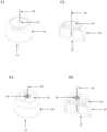
- Figures 15A1-3 show side view (15A1) , top view (15A2) , and cross-sectional view (15A3) of introducer tip 22, according to some embodiments.
- Introducer 20, in some embodiments, includes a U-shape cross section having at least one and preferably two longitudinal protrusions: sensor probe holders 23, configured to support sensor probe 60 when it is coupled with introducer 20.
- Figures 15B1-2 show a side view (15B1) and a top view (15B2) of introducer tip 22 and sensor probe tip 60.
- sensor tip 65 has a rectangular shape.
- Figure 15C shows a top view of a sharp tip 22 of the introducer, and sensor tip 65 of probe 60 (here, sensor tip 65 has a square shape).
- Figures 15D1 and 15D2 show schemes, according to some embodiments, of the senor probe tip having a sharp end.
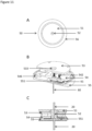
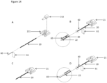
- Figures 16A - C and 16A1 - C1 show spatial (16A-C) and magnified (16A1-C1) views, of the sensor 50, sensor probe 60, introducer tip 22, and sensor tip 65, according to some embodiments, during a first mounting phase and a second mounting phase. Since it is desired to minimize traumatic injury at the tissue surrounding the sensor probe tip and minimize the consequent inflammatory reaction because inflammation reduces the electrodes sensitivity to glucose, in the first mounting phase, the coupled introducer 20 and sensor probe 60 are concomitantly inserted into the subcutaneous tissue.
- sensor probe 60 is further displaced (e.g., 1-3mm) in the same (first/forward) direction (i.e., there is a relative movement between introducer 20 and sensor probe 60).
- sensor probe tip 65 is located distally to the introducer tip 22.
- the sensor probe 60 is relatively thin 50-100 microns such that and movement within the subcutaneous tissue causes minimal trauma.
- Figures 16A - A1 show sensor probe 60 coupled with introducer 20 before insertion - sensor probe tip 65 resides within the introducer 20.
- Figures 17 and 18 show an assembly process of mounting assembly 1, according to some embodiments.
- probe compartment 6 is assembled and then sterilized (e.g., gamma, e-beam radiation). The probe compartment 6 is then sealed and provides protection to sensor probe 60 against biologic and chemical contamination.
- probe compartment 6 is comprised of at least a portion of mounting assembly 1 and at least a portion of sensor 50 (e.g., Figures 1 - 3 ). Following sterilization of the probe compartment 6, the non-sterilized spring compartment 9 can be assembled adjacent (e.g., on-top) of sterilized probe compartment 6 (e.g., in a clean room).
- the spring compartment 9, in some embodiments, comprises at least a portion of mounting assembly 1 and at least a portion of sensor 50 (see e.g., Figures 1- 3 ).
- Figures 17A-B show exploded view (17A) and oblique cross section view (17B) of the sterilized, sealed compartment (probe compartment 6), according to some embodiments.
- the probe compartment 6 can include a plurality of, and in some embodiments, all of (parts stacked, e.g., from the bottom-up) protecting lid 17, protecting lid seal 174, probe compartment seal 162, probe compartment housing 16, adhesive 56, sensor housing lower cover 55, sensor base plate, 54, introducer 20, base plate seal 546, sensor probe 60, and contacts plate 61.
- Figures 18A1 - F1 and 18A2 - F2 show spatial views (18A1 - F1 ) and oblique views (18A2 - F2) , respectively, of the various assembly stages of the mounting assembly 1, according to some embodiments.
- Figures 18A1-2 show sterile probe compartment 6 after assembly (e.g., assembly process shown in Figure 17 ) and sterilization.
- the sterile probe/compartment (probe compartment 6) can include a plurality of, and in some embodiments, all of protecting lid 17, probe compartment housing 16, sensor base plate 54, and introducer 20.
- Figures 18B1-2 show the assembled PCBA 53, according to some embodiments
- Figures 18C1-2 show the assembled sensor housing upper cover 51, according to some embodiments
- Figures 18D1-2 show the assembled spring compartment base 15 and the retraction spring 32, according to some embodiments.
- Figures 18E1-2 show the assembled introducer cap 21, according to some embodiments
- Figures 18F1-2 show spring compartment housing 19 and insertion spring loaded mechanism (operating button 11, other component are shown in Figures 2-6 ), according to some embodiments.
- a reference to "A and/or B", when used in conjunction with open-ended language such as “comprising” can refer, in one embodiment, to A only (optionally including elements other than B); in another embodiment, to B only (optionally including elements other than A); in yet another embodiment, to both A and B (optionally including other elements); etc.
- the phrase "at least one,” in reference to a list of one or more elements, should be understood to mean at least one element selected from any one or more of the elements in the list of elements, but not necessarily including at least one of each and every element specifically listed within the list of elements and not excluding any combinations of elements in the list of elements.
- This definition also allows that elements may optionally be present other than the elements specifically identified within the list of elements to which the phrase "at least one" refers, whether related or unrelated to those elements specifically identified.
- At least one of A and B can refer, in one embodiment, to at least one, optionally including more than one, A, with no B present (and optionally including elements other than B); in another embodiment, to at least one, optionally including more than one, B, with no A present (and optionally including elements other than A); in yet another embodiment, to at least one, optionally including more than one, A, and at least one, optionally including more than one, B (and optionally including other elements); etc.
Landscapes
- Health & Medical Sciences (AREA)
- Life Sciences & Earth Sciences (AREA)
- Physics & Mathematics (AREA)
- General Health & Medical Sciences (AREA)
- Pathology (AREA)
- Molecular Biology (AREA)
- Biomedical Technology (AREA)
- Medical Informatics (AREA)
- Engineering & Computer Science (AREA)
- Surgery (AREA)
- Animal Behavior & Ethology (AREA)
- Biophysics (AREA)
- Public Health (AREA)
- Veterinary Medicine (AREA)
- Heart & Thoracic Surgery (AREA)
- Optics & Photonics (AREA)
- Chemical & Material Sciences (AREA)
- Chemical Kinetics & Catalysis (AREA)
- Emergency Medicine (AREA)
- General Chemical & Material Sciences (AREA)
- Electrochemistry (AREA)
- Analytical Chemistry (AREA)
- Biochemistry (AREA)
- General Physics & Mathematics (AREA)
- Immunology (AREA)
- Measurement Of The Respiration, Hearing Ability, Form, And Blood Characteristics Of Living Organisms (AREA)
- Apparatus Associated With Microorganisms And Enzymes (AREA)
Applications Claiming Priority (3)
| Application Number | Priority Date | Filing Date | Title |
|---|---|---|---|
| US202063070735P | 2020-08-26 | 2020-08-26 | |
| US202063072050P | 2020-08-28 | 2020-08-28 | |
| PCT/IL2021/051052 WO2022044017A1 (en) | 2020-08-26 | 2021-08-26 | Continuous glucose sensor and mounting assembly |
Publications (2)
| Publication Number | Publication Date |
|---|---|
| EP4203788A1 EP4203788A1 (en) | 2023-07-05 |
| EP4203788B1 true EP4203788B1 (en) | 2024-10-09 |
Family
ID=78212405
Family Applications (2)
| Application Number | Title | Priority Date | Filing Date |
|---|---|---|---|
| EP21794016.2A Active EP4203788B1 (en) | 2020-08-26 | 2021-08-26 | Continuous glucose sensor and mounting assembly |
| EP21794408.1A Pending EP4203787A2 (en) | 2020-08-26 | 2021-08-26 | Systems, devices and methods for glucose sensing and associated methods |
Family Applications After (1)
| Application Number | Title | Priority Date | Filing Date |
|---|---|---|---|
| EP21794408.1A Pending EP4203787A2 (en) | 2020-08-26 | 2021-08-26 | Systems, devices and methods for glucose sensing and associated methods |
Country Status (6)
| Country | Link |
|---|---|
| US (2) | US20230301556A1 (https=) |
| EP (2) | EP4203788B1 (https=) |
| JP (2) | JP2023538960A (https=) |
| CN (2) | CN115988988A (https=) |
| ES (1) | ES3008508T3 (https=) |
| WO (2) | WO2022044017A1 (https=) |
Families Citing this family (12)
| Publication number | Priority date | Publication date | Assignee | Title |
|---|---|---|---|---|
| USD1013544S1 (en) | 2022-04-29 | 2024-02-06 | Biolinq Incorporated | Wearable sensor |
| CN114609205B (zh) * | 2022-03-17 | 2024-01-30 | 苏州中星医疗技术有限公司 | 一种用于植入电化学生物传感器的参比电极的制备方法 |
| US12087469B2 (en) | 2022-04-14 | 2024-09-10 | Allez Health Inc. | Coating a working wire for a continuous biological sensor |
| USD1012744S1 (en) | 2022-05-16 | 2024-01-30 | Biolinq Incorporated | Wearable sensor with illuminated display |
| US20240225499A9 (en) * | 2022-10-21 | 2024-07-11 | Zense-Life Inc. | Factory Calibration of a Sensor |
| USD1035004S1 (en) | 2023-02-28 | 2024-07-09 | Biolinq Incorporated | Wearable sensor |
| USD1068516S1 (en) | 2023-02-28 | 2025-04-01 | Biolinq Incorporated | Wearable sensor |
| USD1083977S1 (en) | 2023-02-28 | 2025-07-15 | Biolinq Incorporated | Display with graphical user interface for a wearable sensor |
| USD1083640S1 (en) | 2023-05-16 | 2025-07-15 | Biolinq Incorporated | Wearable sensor |
| US20250151929A1 (en) * | 2023-11-09 | 2025-05-15 | Isee Store Innovations, L.L.C. | Product holder systems and methods of forming the same |
| WO2026013601A1 (en) * | 2024-07-11 | 2026-01-15 | Allez Health Inc. | Calibration for a biological sensor |
| WO2026046754A1 (en) | 2024-08-27 | 2026-03-05 | Roche Diabetes Care Gmbh | Continuous analyte sensor system |
Citations (15)
| Publication number | Priority date | Publication date | Assignee | Title |
|---|---|---|---|---|
| WO2004098684A2 (en) | 2003-05-08 | 2004-11-18 | Novo Nordisk A/S | Skin mountable injection device with a detachable needle insertion actuation |
| EP1797817A1 (de) | 2005-12-19 | 2007-06-20 | F.Hoffmann-La Roche Ag | Sandwichsensor zur Ermittlung einer Analytkonzentration |
| US20080234561A1 (en) | 2007-03-20 | 2008-09-25 | Bernd Roesicke | System for in-vivo measurement of an analyte concentration |
| US20080255440A1 (en) | 2004-08-10 | 2008-10-16 | Novo Nordisk A/S | Method of Forming a Sterilized Sensor Package and a Sterilized Sensor Package |
| US20130150691A1 (en) | 2011-12-11 | 2013-06-13 | Abbott Diabetes Care Inc. | Analyte Sensor Devices, Connections, and Methods |
| WO2014055456A1 (en) | 2012-10-07 | 2014-04-10 | Abbott Diabetes Care Inc. | Medical device insertion indicators |
| WO2016020370A1 (en) | 2014-08-06 | 2016-02-11 | Roche Diagnostics Gmbh | Medical device and method for producing a medical device |
| EP3202323A1 (en) | 2016-02-05 | 2017-08-09 | Roche Diabetes Care GmbH | Medical device for detecting at least one analyte in a body fluid |
| WO2017134227A1 (en) | 2016-02-05 | 2017-08-10 | Roche Diabetes Care Gmbh | Medical device for detecting at least one analyte in a body fluid |
| WO2017176802A1 (en) | 2016-04-08 | 2017-10-12 | Medtronic Minimed, Inc. | Analyte sensor |
| WO2018195286A1 (en) | 2017-04-19 | 2018-10-25 | Metronom Health, Inc. | Inserter for an analyte sensors |
| US20180325433A1 (en) | 2017-05-09 | 2018-11-15 | Ascensia Diabetes Care Holdings Ag | Sensor assembly apparatus and methods for continuous glucose monitors |
| WO2019122095A1 (en) | 2017-12-21 | 2019-06-27 | Roche Diabetes Care Gmbh | Medical system and method of manufacturing thereof |
| US20190313950A1 (en) | 2018-04-13 | 2019-10-17 | Ascensia Diabetes Care Holdings Ag | Sensor assembly apparatus and methods for continuous glucose monitors |
| WO2019236876A1 (en) | 2018-06-07 | 2019-12-12 | Abbott Diabetes Care Inc. | Focused sterilization and sterilized sub-assemblies for analyte monitoring systems |
Family Cites Families (15)
| Publication number | Priority date | Publication date | Assignee | Title |
|---|---|---|---|---|
| JPH0743338B2 (ja) * | 1987-07-03 | 1995-05-15 | テルモ株式会社 | マルチセンサ |
| CA2403646A1 (en) * | 2000-03-28 | 2001-10-04 | Inverness Medical Technology, Inc. | Continuous process for manufacture of disposable electro-chemical sensor |
| US8579831B2 (en) * | 2002-04-19 | 2013-11-12 | Sanofi-Aventis Deutschland Gmbh | Method and apparatus for penetrating tissue |
| US7481777B2 (en) * | 2006-01-05 | 2009-01-27 | Roche Diagnostics Operations, Inc. | Lancet integrated test element tape dispenser |
| US20090082693A1 (en) * | 2004-12-29 | 2009-03-26 | Therasense, Inc. | Method and apparatus for providing temperature sensor module in a data communication system |
| EP1972267A1 (de) * | 2007-03-20 | 2008-09-24 | Roche Diagnostics GmbH | System zur in-vivo Messung einer Analytkonzentration |
| JP2009008574A (ja) * | 2007-06-29 | 2009-01-15 | Sumitomo Electric Ind Ltd | センサチップ及びバイオセンサカートリッジ並びにバイオセンサ装置 |
| FI3912551T3 (fi) * | 2009-02-26 | 2023-10-31 | Abbott Diabetes Care Inc | Parannettuja analyyttiantureita ja menetelmiä niiden valmistamiseksi ja käyttämiseksi |
| DK3622883T3 (da) * | 2010-03-24 | 2021-07-19 | Abbott Diabetes Care Inc | Indførerer til medicinsk indretning og fremgangsmåder til at indføre og anvende medicinske indretninger |
| FI2720610T3 (fi) * | 2011-06-17 | 2025-09-30 | Abbott Diabetes Care Inc | Pinottu analyyttianturi, jonka ensimmäinen elektrodi on kapeampi kuin anturin toinen elektrodi |
| US9931065B2 (en) * | 2012-04-04 | 2018-04-03 | Dexcom, Inc. | Transcutaneous analyte sensors, applicators therefor, and associated methods |
| US10426383B2 (en) * | 2013-01-22 | 2019-10-01 | Medtronic Minimed, Inc. | Muting glucose sensor oxygen response and reducing electrode edge growth with pulsed current plating |
| US10251605B2 (en) * | 2015-02-16 | 2019-04-09 | Verily Life Sciences Llc | Bandage type of continuous glucose monitoring system |
| US11512384B2 (en) * | 2017-05-11 | 2022-11-29 | Medtronic Minimed, Inc. | Analyte sensors and methods for fabricating analyte sensors |
| KR102185833B1 (ko) * | 2018-07-31 | 2020-12-03 | 주식회사 아이센스 | 연속 혈당 측정 장치 |
-
2021
- 2021-08-26 CN CN202180051634.8A patent/CN115988988A/zh active Pending
- 2021-08-26 WO PCT/IL2021/051052 patent/WO2022044017A1/en not_active Ceased
- 2021-08-26 ES ES21794016T patent/ES3008508T3/es active Active
- 2021-08-26 US US18/023,322 patent/US20230301556A1/en active Pending
- 2021-08-26 WO PCT/IL2021/051053 patent/WO2022044018A2/en not_active Ceased
- 2021-08-26 JP JP2023513924A patent/JP2023538960A/ja active Pending
- 2021-08-26 EP EP21794016.2A patent/EP4203788B1/en active Active
- 2021-08-26 EP EP21794408.1A patent/EP4203787A2/en active Pending
- 2021-08-26 US US18/023,324 patent/US20230301557A1/en active Pending
- 2021-08-26 CN CN202180056445.XA patent/CN116033870A/zh active Pending
- 2021-08-26 JP JP2023513915A patent/JP2023539653A/ja active Pending
Patent Citations (15)
| Publication number | Priority date | Publication date | Assignee | Title |
|---|---|---|---|---|
| WO2004098684A2 (en) | 2003-05-08 | 2004-11-18 | Novo Nordisk A/S | Skin mountable injection device with a detachable needle insertion actuation |
| US20080255440A1 (en) | 2004-08-10 | 2008-10-16 | Novo Nordisk A/S | Method of Forming a Sterilized Sensor Package and a Sterilized Sensor Package |
| EP1797817A1 (de) | 2005-12-19 | 2007-06-20 | F.Hoffmann-La Roche Ag | Sandwichsensor zur Ermittlung einer Analytkonzentration |
| US20080234561A1 (en) | 2007-03-20 | 2008-09-25 | Bernd Roesicke | System for in-vivo measurement of an analyte concentration |
| US20130150691A1 (en) | 2011-12-11 | 2013-06-13 | Abbott Diabetes Care Inc. | Analyte Sensor Devices, Connections, and Methods |
| WO2014055456A1 (en) | 2012-10-07 | 2014-04-10 | Abbott Diabetes Care Inc. | Medical device insertion indicators |
| WO2016020370A1 (en) | 2014-08-06 | 2016-02-11 | Roche Diagnostics Gmbh | Medical device and method for producing a medical device |
| EP3202323A1 (en) | 2016-02-05 | 2017-08-09 | Roche Diabetes Care GmbH | Medical device for detecting at least one analyte in a body fluid |
| WO2017134227A1 (en) | 2016-02-05 | 2017-08-10 | Roche Diabetes Care Gmbh | Medical device for detecting at least one analyte in a body fluid |
| WO2017176802A1 (en) | 2016-04-08 | 2017-10-12 | Medtronic Minimed, Inc. | Analyte sensor |
| WO2018195286A1 (en) | 2017-04-19 | 2018-10-25 | Metronom Health, Inc. | Inserter for an analyte sensors |
| US20180325433A1 (en) | 2017-05-09 | 2018-11-15 | Ascensia Diabetes Care Holdings Ag | Sensor assembly apparatus and methods for continuous glucose monitors |
| WO2019122095A1 (en) | 2017-12-21 | 2019-06-27 | Roche Diabetes Care Gmbh | Medical system and method of manufacturing thereof |
| US20190313950A1 (en) | 2018-04-13 | 2019-10-17 | Ascensia Diabetes Care Holdings Ag | Sensor assembly apparatus and methods for continuous glucose monitors |
| WO2019236876A1 (en) | 2018-06-07 | 2019-12-12 | Abbott Diabetes Care Inc. | Focused sterilization and sterilized sub-assemblies for analyte monitoring systems |
Also Published As
| Publication number | Publication date |
|---|---|
| EP4203787A2 (en) | 2023-07-05 |
| US20230301557A1 (en) | 2023-09-28 |
| WO2022044018A3 (en) | 2022-04-07 |
| CN115988988A (zh) | 2023-04-18 |
| EP4203788A1 (en) | 2023-07-05 |
| ES3008508T3 (en) | 2025-03-24 |
| WO2022044017A1 (en) | 2022-03-03 |
| WO2022044018A2 (en) | 2022-03-03 |
| ES3008508T8 (en) | 2025-05-14 |
| JP2023538960A (ja) | 2023-09-12 |
| JP2023539653A (ja) | 2023-09-15 |
| US20230301556A1 (en) | 2023-09-28 |
| CN116033870A (zh) | 2023-04-28 |
Similar Documents
| Publication | Publication Date | Title |
|---|---|---|
| EP4203788B1 (en) | Continuous glucose sensor and mounting assembly | |
| US11944433B2 (en) | Detecting an analyte in a body fluid | |
| US11911156B2 (en) | Detecting an analyte in a body fluid | |
| JP7139429B2 (ja) | 医療システムおよびその製造方法 |
Legal Events
| Date | Code | Title | Description |
|---|---|---|---|
| STAA | Information on the status of an ep patent application or granted ep patent |
Free format text: STATUS: UNKNOWN |
|
| STAA | Information on the status of an ep patent application or granted ep patent |
Free format text: STATUS: THE INTERNATIONAL PUBLICATION HAS BEEN MADE |
|
| PUAI | Public reference made under article 153(3) epc to a published international application that has entered the european phase |
Free format text: ORIGINAL CODE: 0009012 |
|
| STAA | Information on the status of an ep patent application or granted ep patent |
Free format text: STATUS: REQUEST FOR EXAMINATION WAS MADE |
|
| 17P | Request for examination filed |
Effective date: 20230324 |
|
| AK | Designated contracting states |
Kind code of ref document: A1 Designated state(s): AL AT BE BG CH CY CZ DE DK EE ES FI FR GB GR HR HU IE IS IT LI LT LU LV MC MK MT NL NO PL PT RO RS SE SI SK SM TR |
|
| DAV | Request for validation of the european patent (deleted) | ||
| DAX | Request for extension of the european patent (deleted) | ||
| GRAP | Despatch of communication of intention to grant a patent |
Free format text: ORIGINAL CODE: EPIDOSNIGR1 |
|
| STAA | Information on the status of an ep patent application or granted ep patent |
Free format text: STATUS: GRANT OF PATENT IS INTENDED |
|
| INTG | Intention to grant announced |
Effective date: 20240510 |
|
| GRAS | Grant fee paid |
Free format text: ORIGINAL CODE: EPIDOSNIGR3 |
|
| GRAA | (expected) grant |
Free format text: ORIGINAL CODE: 0009210 |
|
| STAA | Information on the status of an ep patent application or granted ep patent |
Free format text: STATUS: THE PATENT HAS BEEN GRANTED |
|
| AK | Designated contracting states |
Kind code of ref document: B1 Designated state(s): AL AT BE BG CH CY CZ DE DK EE ES FI FR GB GR HR HU IE IS IT LI LT LU LV MC MK MT NL NO PL PT RO RS SE SI SK SM TR |
|
| REG | Reference to a national code |
Ref country code: CH Ref legal event code: EP |
|
| REG | Reference to a national code |
Ref country code: DE Ref legal event code: R096 Ref document number: 602021020059 Country of ref document: DE |
|
| REG | Reference to a national code |
Ref country code: IE Ref legal event code: FG4D |
|
| P01 | Opt-out of the competence of the unified patent court (upc) registered |
Free format text: CASE NUMBER: APP_53407/2024 Effective date: 20240926 |
|
| REG | Reference to a national code |
Ref country code: LT Ref legal event code: MG9D |
|
| REG | Reference to a national code |
Ref country code: NL Ref legal event code: MP Effective date: 20241009 |
|
| REG | Reference to a national code |
Ref country code: AT Ref legal event code: MK05 Ref document number: 1729655 Country of ref document: AT Kind code of ref document: T Effective date: 20241009 |
|
| PG25 | Lapsed in a contracting state [announced via postgrant information from national office to epo] |
Ref country code: NL Free format text: LAPSE BECAUSE OF FAILURE TO SUBMIT A TRANSLATION OF THE DESCRIPTION OR TO PAY THE FEE WITHIN THE PRESCRIBED TIME-LIMIT Effective date: 20241009 |
|
| REG | Reference to a national code |
Ref country code: ES Ref legal event code: FG2A Ref document number: 3008508 Country of ref document: ES Kind code of ref document: T3 Effective date: 20250324 |
|
| PG25 | Lapsed in a contracting state [announced via postgrant information from national office to epo] |
Ref country code: NL Free format text: LAPSE BECAUSE OF FAILURE TO SUBMIT A TRANSLATION OF THE DESCRIPTION OR TO PAY THE FEE WITHIN THE PRESCRIBED TIME-LIMIT Effective date: 20241009 |
|
| PG25 | Lapsed in a contracting state [announced via postgrant information from national office to epo] |
Ref country code: HR Free format text: LAPSE BECAUSE OF FAILURE TO SUBMIT A TRANSLATION OF THE DESCRIPTION OR TO PAY THE FEE WITHIN THE PRESCRIBED TIME-LIMIT Effective date: 20241009 Ref country code: PT Free format text: LAPSE BECAUSE OF FAILURE TO SUBMIT A TRANSLATION OF THE DESCRIPTION OR TO PAY THE FEE WITHIN THE PRESCRIBED TIME-LIMIT Effective date: 20250210 Ref country code: IS Free format text: LAPSE BECAUSE OF FAILURE TO SUBMIT A TRANSLATION OF THE DESCRIPTION OR TO PAY THE FEE WITHIN THE PRESCRIBED TIME-LIMIT Effective date: 20250209 |
|
| PG25 | Lapsed in a contracting state [announced via postgrant information from national office to epo] |
Ref country code: FI Free format text: LAPSE BECAUSE OF FAILURE TO SUBMIT A TRANSLATION OF THE DESCRIPTION OR TO PAY THE FEE WITHIN THE PRESCRIBED TIME-LIMIT Effective date: 20241009 |
|
| PG25 | Lapsed in a contracting state [announced via postgrant information from national office to epo] |
Ref country code: BG Free format text: LAPSE BECAUSE OF FAILURE TO SUBMIT A TRANSLATION OF THE DESCRIPTION OR TO PAY THE FEE WITHIN THE PRESCRIBED TIME-LIMIT Effective date: 20241009 |
|
| PG25 | Lapsed in a contracting state [announced via postgrant information from national office to epo] |
Ref country code: NO Free format text: LAPSE BECAUSE OF FAILURE TO SUBMIT A TRANSLATION OF THE DESCRIPTION OR TO PAY THE FEE WITHIN THE PRESCRIBED TIME-LIMIT Effective date: 20250109 |
|
| PG25 | Lapsed in a contracting state [announced via postgrant information from national office to epo] |
Ref country code: LV Free format text: LAPSE BECAUSE OF FAILURE TO SUBMIT A TRANSLATION OF THE DESCRIPTION OR TO PAY THE FEE WITHIN THE PRESCRIBED TIME-LIMIT Effective date: 20241009 Ref country code: GR Free format text: LAPSE BECAUSE OF FAILURE TO SUBMIT A TRANSLATION OF THE DESCRIPTION OR TO PAY THE FEE WITHIN THE PRESCRIBED TIME-LIMIT Effective date: 20250110 Ref country code: AT Free format text: LAPSE BECAUSE OF FAILURE TO SUBMIT A TRANSLATION OF THE DESCRIPTION OR TO PAY THE FEE WITHIN THE PRESCRIBED TIME-LIMIT Effective date: 20241009 |
|
| PG25 | Lapsed in a contracting state [announced via postgrant information from national office to epo] |
Ref country code: PL Free format text: LAPSE BECAUSE OF FAILURE TO SUBMIT A TRANSLATION OF THE DESCRIPTION OR TO PAY THE FEE WITHIN THE PRESCRIBED TIME-LIMIT Effective date: 20241009 |
|
| PG25 | Lapsed in a contracting state [announced via postgrant information from national office to epo] |
Ref country code: RS Free format text: LAPSE BECAUSE OF FAILURE TO SUBMIT A TRANSLATION OF THE DESCRIPTION OR TO PAY THE FEE WITHIN THE PRESCRIBED TIME-LIMIT Effective date: 20250109 |
|
| PG25 | Lapsed in a contracting state [announced via postgrant information from national office to epo] |
Ref country code: SM Free format text: LAPSE BECAUSE OF FAILURE TO SUBMIT A TRANSLATION OF THE DESCRIPTION OR TO PAY THE FEE WITHIN THE PRESCRIBED TIME-LIMIT Effective date: 20241009 |
|
| REG | Reference to a national code |
Ref country code: DE Ref legal event code: R026 Ref document number: 602021020059 Country of ref document: DE |
|
| PG25 | Lapsed in a contracting state [announced via postgrant information from national office to epo] |
Ref country code: DK Free format text: LAPSE BECAUSE OF FAILURE TO SUBMIT A TRANSLATION OF THE DESCRIPTION OR TO PAY THE FEE WITHIN THE PRESCRIBED TIME-LIMIT Effective date: 20241009 |
|
| PLBI | Opposition filed |
Free format text: ORIGINAL CODE: 0009260 |
|
| PG25 | Lapsed in a contracting state [announced via postgrant information from national office to epo] |
Ref country code: EE Free format text: LAPSE BECAUSE OF FAILURE TO SUBMIT A TRANSLATION OF THE DESCRIPTION OR TO PAY THE FEE WITHIN THE PRESCRIBED TIME-LIMIT Effective date: 20241009 |
|
| PLAX | Notice of opposition and request to file observation + time limit sent |
Free format text: ORIGINAL CODE: EPIDOSNOBS2 |
|
| PG25 | Lapsed in a contracting state [announced via postgrant information from national office to epo] |
Ref country code: RO Free format text: LAPSE BECAUSE OF FAILURE TO SUBMIT A TRANSLATION OF THE DESCRIPTION OR TO PAY THE FEE WITHIN THE PRESCRIBED TIME-LIMIT Effective date: 20241009 |
|
| PG25 | Lapsed in a contracting state [announced via postgrant information from national office to epo] |
Ref country code: SK Free format text: LAPSE BECAUSE OF FAILURE TO SUBMIT A TRANSLATION OF THE DESCRIPTION OR TO PAY THE FEE WITHIN THE PRESCRIBED TIME-LIMIT Effective date: 20241009 |
|
| PG25 | Lapsed in a contracting state [announced via postgrant information from national office to epo] |
Ref country code: CZ Free format text: LAPSE BECAUSE OF FAILURE TO SUBMIT A TRANSLATION OF THE DESCRIPTION OR TO PAY THE FEE WITHIN THE PRESCRIBED TIME-LIMIT Effective date: 20241009 |
|
| 26 | Opposition filed |
Opponent name: ROCHE DIABETES CARE GMBH Effective date: 20250704 |
|
| PG25 | Lapsed in a contracting state [announced via postgrant information from national office to epo] |
Ref country code: SE Free format text: LAPSE BECAUSE OF FAILURE TO SUBMIT A TRANSLATION OF THE DESCRIPTION OR TO PAY THE FEE WITHIN THE PRESCRIBED TIME-LIMIT Effective date: 20241009 |
|
| PGFP | Annual fee paid to national office [announced via postgrant information from national office to epo] |
Ref country code: ES Payment date: 20250902 Year of fee payment: 5 |
|
| PGFP | Annual fee paid to national office [announced via postgrant information from national office to epo] |
Ref country code: DE Payment date: 20250827 Year of fee payment: 5 |
|
| PGFP | Annual fee paid to national office [announced via postgrant information from national office to epo] |
Ref country code: IT Payment date: 20250827 Year of fee payment: 5 |
|
| PGFP | Annual fee paid to national office [announced via postgrant information from national office to epo] |
Ref country code: GB Payment date: 20250825 Year of fee payment: 5 |
|
| PGFP | Annual fee paid to national office [announced via postgrant information from national office to epo] |
Ref country code: FR Payment date: 20250822 Year of fee payment: 5 |
|
| PLBB | Reply of patent proprietor to notice(s) of opposition received |
Free format text: ORIGINAL CODE: EPIDOSNOBS3 |
|
| REG | Reference to a national code |
Ref country code: CH Ref legal event code: H13 Free format text: ST27 STATUS EVENT CODE: U-0-0-H10-H13 (AS PROVIDED BY THE NATIONAL OFFICE) Effective date: 20260324 |
|
| PG25 | Lapsed in a contracting state [announced via postgrant information from national office to epo] |
Ref country code: MC Free format text: LAPSE BECAUSE OF FAILURE TO SUBMIT A TRANSLATION OF THE DESCRIPTION OR TO PAY THE FEE WITHIN THE PRESCRIBED TIME-LIMIT Effective date: 20241009 |
|
| PG25 | Lapsed in a contracting state [announced via postgrant information from national office to epo] |
Ref country code: LU Free format text: LAPSE BECAUSE OF NON-PAYMENT OF DUE FEES Effective date: 20250826 |