EP4203533A1 - Anchor key generation method, device, and system - Google Patents
Anchor key generation method, device, and system Download PDFInfo
- Publication number
- EP4203533A1 EP4203533A1 EP22210348.3A EP22210348A EP4203533A1 EP 4203533 A1 EP4203533 A1 EP 4203533A1 EP 22210348 A EP22210348 A EP 22210348A EP 4203533 A1 EP4203533 A1 EP 4203533A1
- Authority
- EP
- European Patent Office
- Prior art keywords
- key
- anchor
- amf
- identifier
- access
- Prior art date
- Legal status (The legal status is an assumption and is not a legal conclusion. Google has not performed a legal analysis and makes no representation as to the accuracy of the status listed.)
- Pending
Links
- 238000000034 method Methods 0.000 title claims abstract description 130
- 238000004422 calculation algorithm Methods 0.000 claims description 145
- 238000004590 computer program Methods 0.000 claims description 9
- DJGAAPFSPWAYTJ-UHFFFAOYSA-M metamizole sodium Chemical compound [Na+].O=C1C(N(CS([O-])(=O)=O)C)=C(C)N(C)N1C1=CC=CC=C1 DJGAAPFSPWAYTJ-UHFFFAOYSA-M 0.000 description 91
- 230000008569 process Effects 0.000 description 40
- 238000010586 diagram Methods 0.000 description 31
- 238000009795 derivation Methods 0.000 description 20
- 238000007726 management method Methods 0.000 description 15
- 230000006870 function Effects 0.000 description 14
- GVVPGTZRZFNKDS-JXMROGBWSA-N geranyl diphosphate Chemical compound CC(C)=CCC\C(C)=C\CO[P@](O)(=O)OP(O)(O)=O GVVPGTZRZFNKDS-JXMROGBWSA-N 0.000 description 14
- 238000000926 separation method Methods 0.000 description 14
- 230000003993 interaction Effects 0.000 description 10
- 238000012545 processing Methods 0.000 description 9
- 238000013523 data management Methods 0.000 description 8
- 230000006399 behavior Effects 0.000 description 4
- 230000000737 periodic effect Effects 0.000 description 4
- 238000004364 calculation method Methods 0.000 description 2
- 238000013507 mapping Methods 0.000 description 2
- 238000012986 modification Methods 0.000 description 2
- 230000004048 modification Effects 0.000 description 2
- 230000004069 differentiation Effects 0.000 description 1
- 230000005611 electricity Effects 0.000 description 1
- 238000005516 engineering process Methods 0.000 description 1
- 239000000835 fiber Substances 0.000 description 1
- 230000003287 optical effect Effects 0.000 description 1
- 230000011664 signaling Effects 0.000 description 1
- XLYOFNOQVPJJNP-UHFFFAOYSA-N water Substances O XLYOFNOQVPJJNP-UHFFFAOYSA-N 0.000 description 1
Images


Classifications
-
- H—ELECTRICITY
- H04—ELECTRIC COMMUNICATION TECHNIQUE
- H04W—WIRELESS COMMUNICATION NETWORKS
- H04W12/00—Security arrangements; Authentication; Protecting privacy or anonymity
- H04W12/04—Key management, e.g. using generic bootstrapping architecture [GBA]
- H04W12/041—Key generation or derivation
-
- H—ELECTRICITY
- H04—ELECTRIC COMMUNICATION TECHNIQUE
- H04L—TRANSMISSION OF DIGITAL INFORMATION, e.g. TELEGRAPHIC COMMUNICATION
- H04L63/00—Network architectures or network communication protocols for network security
- H04L63/08—Network architectures or network communication protocols for network security for authentication of entities
- H04L63/0869—Network architectures or network communication protocols for network security for authentication of entities for achieving mutual authentication
-
- H—ELECTRICITY
- H04—ELECTRIC COMMUNICATION TECHNIQUE
- H04L—TRANSMISSION OF DIGITAL INFORMATION, e.g. TELEGRAPHIC COMMUNICATION
- H04L9/00—Cryptographic mechanisms or cryptographic arrangements for secret or secure communications; Network security protocols
- H04L9/08—Key distribution or management, e.g. generation, sharing or updating, of cryptographic keys or passwords
- H04L9/0861—Generation of secret information including derivation or calculation of cryptographic keys or passwords
-
- H—ELECTRICITY
- H04—ELECTRIC COMMUNICATION TECHNIQUE
- H04W—WIRELESS COMMUNICATION NETWORKS
- H04W12/00—Security arrangements; Authentication; Protecting privacy or anonymity
- H04W12/04—Key management, e.g. using generic bootstrapping architecture [GBA]
-
- H—ELECTRICITY
- H04—ELECTRIC COMMUNICATION TECHNIQUE
- H04W—WIRELESS COMMUNICATION NETWORKS
- H04W12/00—Security arrangements; Authentication; Protecting privacy or anonymity
- H04W12/04—Key management, e.g. using generic bootstrapping architecture [GBA]
- H04W12/043—Key management, e.g. using generic bootstrapping architecture [GBA] using a trusted network node as an anchor
- H04W12/0431—Key distribution or pre-distribution; Key agreement
-
- H—ELECTRICITY
- H04—ELECTRIC COMMUNICATION TECHNIQUE
- H04W—WIRELESS COMMUNICATION NETWORKS
- H04W12/00—Security arrangements; Authentication; Protecting privacy or anonymity
- H04W12/04—Key management, e.g. using generic bootstrapping architecture [GBA]
- H04W12/043—Key management, e.g. using generic bootstrapping architecture [GBA] using a trusted network node as an anchor
- H04W12/0433—Key management protocols
-
- H—ELECTRICITY
- H04—ELECTRIC COMMUNICATION TECHNIQUE
- H04W—WIRELESS COMMUNICATION NETWORKS
- H04W76/00—Connection management
- H04W76/10—Connection setup
- H04W76/11—Allocation or use of connection identifiers
-
- H—ELECTRICITY
- H04—ELECTRIC COMMUNICATION TECHNIQUE
- H04W—WIRELESS COMMUNICATION NETWORKS
- H04W76/00—Connection management
- H04W76/20—Manipulation of established connections
- H04W76/25—Maintenance of established connections
-
- H—ELECTRICITY
- H04—ELECTRIC COMMUNICATION TECHNIQUE
- H04W—WIRELESS COMMUNICATION NETWORKS
- H04W8/00—Network data management
- H04W8/02—Processing of mobility data, e.g. registration information at HLR [Home Location Register] or VLR [Visitor Location Register]; Transfer of mobility data, e.g. between HLR, VLR or external networks
- H04W8/08—Mobility data transfer
-
- H—ELECTRICITY
- H04—ELECTRIC COMMUNICATION TECHNIQUE
- H04W—WIRELESS COMMUNICATION NETWORKS
- H04W80/00—Wireless network protocols or protocol adaptations to wireless operation
- H04W80/08—Upper layer protocols
- H04W80/10—Upper layer protocols adapted for application session management, e.g. SIP [Session Initiation Protocol]
-
- H—ELECTRICITY
- H04—ELECTRIC COMMUNICATION TECHNIQUE
- H04W—WIRELESS COMMUNICATION NETWORKS
- H04W88/00—Devices specially adapted for wireless communication networks, e.g. terminals, base stations or access point devices
- H04W88/02—Terminal devices
- H04W88/022—Selective call receivers
- H04W88/023—Selective call receivers with message or information receiving capability
Definitions
- step 509 to step 511 may be replaced with the following steps 5112 to 5116.
- K left trunc (EMSK or MSK).
- This formula means that some bits of the EMSK or the MSK are directly truncated as K left , and trunc is used to truncate a value.
- trunc(number) indicates truncating a number
- trunc(date) indicates truncating a date.
Abstract
Description
- The present disclosure relates to the communications field, and in particular, to an anchor key generation method, device, and system.
- A key is critical to an encryption operation, a decryption operation, and a cryptosystem. Therefore, in an information security system, key negotiation is an important part in an authentication process.
FIG. 1 shows a key negotiation process in an existing 4G system. Network elements required for executing the process include user equipment (UE), an eNodeB, a mobility management entity (MME), a home subscriber server (HSS), an authentication center (AuC), and the like. The execution process is roughly as follows: - Step 1: The AuC generates an integrity key IK and a cipher key CK based on a root key K, and sends the integrity key IK and the cipher key CK to the HSS. Correspondingly, the HSS receives the integrity key IK and the cipher key CK sent by the AuC.
- Step 2: The HSS generates an intermediate key KASME based on the integrity key IK and the cipher key CK, and sends the intermediate key KASME to the MME. Correspondingly, the MME receives the intermediate key KASME sent by the HSS.
- Step 3: The MME generates, based on the intermediate key KASME, a NAS integrity key KNASenc for performing encryption protection on a non-access stratum (NAS) message, and a NAS integrity protection key KNASint for performing integrity protection.
- Step 4: The MME generates a base station key KeNB based on the intermediate key KASME, and sends the base station key KeNB to the eNodeB. Correspondingly, the eNodeB receives the base station key KeNB sent by the MME.
- Step 5: The eNodeB separately generates, based on the base station key KeNB, a user plane cipher key KUPenc for performing encryption protection on user plane data, a user plane integrity key KUPint for performing integrity protection on the user plane data, a control plane cipher key KRRCenc for performing encryption protection on control plane data, and a control plane integrity key KRRCint for performing integrity protection on the control plane data.
- Step 6: The UE generates by itself an integrity key IK, a cipher key CK, an intermediate key KASME, a user plane cipher key KUPenc, a user plane integrity key KUPint, a control plane cipher key KRRCenc, and a control plane integrity key KRRCint based on the root key K.
- After the key negotiation process shown in
FIG. 1 is completed, a key architecture shown inFIG. 2 is generated in the 4G system. - It may be understood that
FIG. 1 shows a key negotiation process in a process of accessing a core network by a terminal in a 3rd Generation Partnership Project (3GPP) access mode in a 4G application scenario. To meet requirements of various application scenarios, the terminal may access the core network in various different access modes, for example, a 3GPP access mode, a trusted non-3GPP access mode, and an untrusted 3GPP access mode. In different access modes, key negotiation processes are also different. In a 5G standard, it is specified that one unified anchor key needs to be generated in key negotiation processes of different access modes, so as to implement compatibility with various access modes. However, how to generate the unified anchor key is a problem that a person skilled in the art needs to resolve. - Embodiments of this application provide an anchor key generation method, device, and system, to generate a unified anchor key for different access modes, and implement separation between an anchor key of different access modes and a lower-layer key generated based on the anchor key.
- A first aspect provides an anchor key generation method, including: receiving, by a first communications device, an indication identifier sent by a second communications device, where the indication identifier is used to indicate an access mode of a terminal; sending, by the first communications device, the indication identifier to a third communications device; receiving, by the first communications device, an intermediate key returned by the third communications device, where the intermediate key is generated based on the indication identifier; generating, by the first communications device, an anchor key based on the intermediate key, where the anchor key is corresponding to the access mode of the terminal; and sending, by the first communications device, the anchor key to the second communications device, so that the second communications device derives a lower-layer key for the access mode based on the anchor key.
- In some possible implementations, the access mode is distinguished based on at least one of an access type and an operator type.
- In some possible implementations, the generating, by the first communications device, an anchor key based on the intermediate key is specifically:
- generating, by the first communications device, the anchor key based on the following formula:

- where, anchor key is the anchor key, (IK1', CK1') is the intermediate key, IK1' is an intermediate integrity key, CK1' is an intermediate cipher key, and ∥ means concatenation, indicating that characters on both sides of the symbol are connected in series.
- The first communications device may generate the intermediate key in at least the following two manners:
- When the indication identifier includes an access type identifier and an operator type identifier, the intermediate key is generated based on the following formula:

- When the indication identifier is an NAI, the intermediate key is generated based on the following formula:

- In some possible implementations, the first communications device generates the intermediate key based on the following formula:

- The first communications device generates an EMSK' based on the following formula:

- The first communications device generates the anchor key based on the following formula:

- A second aspect provides a communications device, including a receiving module, a sending module, and a generation module, where the receiving module is configured to receive an indication identifier sent by a second communications device, where the indication identifier is used to indicate an access mode of a terminal; the sending module is configured to send the indication identifier to a third communications device; the receiving module is configured to receive an intermediate key returned by the third communications device, where the intermediate key is generated based on the indication identifier; the generation module is configured to generate an anchor key based on the intermediate key, where the anchor key is corresponding to the access mode of the terminal; and the sending module is configured to send the anchor key to the second communications device, so that the second communications device derives a lower-layer key for the access mode based on the anchor key.
- In some possible implementations, the access mode is distinguished based on at least one of an access type and an operator type.
- In some possible implementations, the generation module is configured to generate the anchor key based on the following formula:

- The first communications device may generate the intermediate key in at least the following two manners:
- When the indication identifier includes an access type identifier and an operator type identifier, the generation module is configured to generate the intermediate key based on the following formula:

- When the indication identifier is an NAI, the generation module is configured to generate the intermediate key based on the following formula:

- In some possible implementations, the generation module is configured to generate the intermediate key based on the following formula:

- The generation module is configured to generate an EMSK' based on the following formula:

- The generation module is configured to generate the anchor key based on the following formula:

- A third aspect provides a communications device, including a memory, a processor coupled to the memory, and a communications module, where the communications module is configured to send or receive data sent from the outside, the memory is configured to store implementation code of the method described in the first aspect, and the processor is configured to execute the program code stored in the memory, namely, execute the method described in the first aspect.
- A fourth aspect provides a computer readable storage medium. The computer readable storage medium stores an instruction. When the instruction is run on a computer, the computer executes the method described in the first aspect.
- A fifth aspect provides a computer program product that includes an instruction. When the instruction is run on a computer, the computer executes the method described in the first aspect.
- A sixth aspect provides a communications system, including an access and mobility control function network element, a session management network element, an authentication server, and a unified data management network element that are connected to each other, where the authentication server is the authentication server according to the second aspect or the third aspect in the claims.
- To describe the technical solutions in the embodiments of the present invention or in the background more clearly, the following briefly describes the accompanying drawings required for describing the embodiments of the present invention or the background.
-
FIG. 1 is a schematic diagram of a key negotiation process in a 3GPP access mode in a 4G application scenario according to the prior art; -
FIG. 2 is a key architectural diagram of the key negotiation process shown inFIG. 1 ; -
FIG. 3 is a network architectural diagram of accessing a 5G core network in a 3GPP access mode related to an embodiment of this application; -
FIG. 4 is a network architectural diagram of accessing a 5G core network in a non-3GPP access mode related to an embodiment of this application; -
FIG. 5 is an interaction diagram of a first anchor key generation method according to an embodiment of this application; -
FIG. 6A andFIG. 6B are specific interaction diagrams of the anchor key generation method shown inFIG. 5 in a 3GPP mode and in a non-3GPP mode, respectively; -
FIG. 7 is a key architectural diagram obtained by using the anchor key generation method shown inFIG. 5 ; -
FIG. 8 is an interaction diagram of a second anchor key generation method according to an embodiment of this application; -
FIG. 9 is an interaction diagram of a third anchor key generation method according to an embodiment of this application; -
FIG. 10 is a key architectural diagram obtained by using the anchor key generation method shown inFIG. 9 ; -
FIG. 11A andFIG. 11B are an interaction diagram of a fourth anchor key generation method according to an embodiment of this application; -
FIG. 12 is a key architectural diagram obtained by using the anchor key generation method shown inFIG. 11A andFIG. 11B ; -
FIG. 13 is an interaction diagram of a fifth anchor key generation method according to an embodiment of this application; -
FIG. 14A andFIG. 14B are specific interaction diagrams of the anchor key generation method shown inFIG. 13 in a 3GPP mode and in a non-3GPP mode, respectively; -
FIG. 15 is a key architectural diagram obtained by using the anchor key generation method shown inFIG. 13 ; -
FIG. 16 is an interaction diagram of a sixth anchor key generation method according to an embodiment of this application; -
FIG. 17A andFIG. 17B are specific interaction diagrams of the anchor key generation method shown inFIG. 16 in a 3GPP mode and in a non-3GPP mode, respectively; -
FIG. 18 is a key architectural diagram obtained by using the anchor key generation method shown inFIG. 16 ; -
FIG. 19 is an interaction diagram of a seventh anchor key generation method according to an embodiment of this application; -
FIG. 20 is a key architectural diagram obtained by using the anchor key generation method shown inFIG. 19 ; -
FIG. 21 is a schematic structural diagram of a communications device according to an embodiment of this application; and -
FIG. 22 is a schematic structural diagram of another communications device according to an embodiment of this application. - The following separately describes a plurality of embodiments of this application with reference to the accompanying drawings and specific embodiments.
-
FIG. 3 is a network architectural diagram related to an embodiment of this application. The network architecture is mainly applicable to a scenario in which a 5G core network is accessed in a 3GPP mode.FIG. 4 is another network architectural diagram related to an embodiment of this application. The network architecture is mainly applicable to a scenario in which a 5G core network is accessed in a non-3GPP mode. Both the network architectures shown inFIG. 3 andFIG. 4 include network elements related to key negotiation: a terminal, an access node (Access node, AN) (namely, N3IWF inFIG. 4 ), an access and mobility control function network element (AMF), a session management network element (SMF), an authentication server (AUSF), and a unified data management network element (UDM). - It should be noted that a security anchor (Security Anchor Function, SEAF) may be deployed in the AMF, and an authentication credential repository and processing function network element (ARPF) may be deployed in the UDM. Certainly, the SEAF may not be deployed in the AMF, but is deployed independently of the AMF. Similarly, the ARPF may not be deployed in the UDM, but is deployed independently of the UDM.
- The following separately and briefly describes the network elements related to key negotiation (the terminal, the AN, the AMF, the SMF, the AUSF, and the UDM).
- The terminal may be specifically any one of UE, a communications device, and an Internet of Things ( IoT) device. The user equipment may be a smartphone, a smartwatch, a smart tablet, or the like. The communications device may be a server, a gateway (GW), a base station, a controller, or the like. The Internet of Things device may be a sensor, an electricity meter, a water meter, or the like.
- The AN may be a wireless access point, for example, a base station, a Wi-Fi (Wireless Fidelity) access point, or a Bluetooth access point; or may be a wired access point, for example, a gateway, a modem, fiber access, or IP access.
- The AMF is responsible for access control and mobility management, and is a forwarding and processing node of non-access stratum (NAS) signaling.
- The SMF is configured to execute establishment and management of a session, a slice, a flow, or a bearer. Subsequently, a physical entity that executes the function of the session management network element may be referred to as a session management device or an SM. The establishment and management of the slice, the flow, or the bearer are in the charge of the mobility management network element.
- The AUSF is responsible for generating, managing, and negotiating a key. The AUSF may be separately deployed as an independent logical functional entity, or may be integrated into a mobility management (Mobility Management) network element, namely, a device such as the AMF or the session management network element SMF; and may be an authentication node of EPS AKA or EAP AKA', or a node of another authentication protocol.
- The UDM means unified data management and mainly includes two parts: One part is a front end of a service or an application, and the other part is a user database. Specifically, the unified data management includes credential processing, location management, subscription data management, policy control, and the like, and also includes information storage of the related processing.
- The SEAF, as a node that has a security authentication function, may be an authentication node of EAP AKA or EAP AKA' or a node of another authentication protocol. For example, when an authentication process is EPS AKA, the SEAF is to receive an intermediate key Kasme.
- The ARPF stores a security credential and uses the security credential to perform a security-related operation, for example, generating a key and storing a security file. The ARPF should be deployed at a physically secure position, and can interact with the AUSF. In actual deployment, the ARPF may be a module of the UDM or is a separate network entity deployed with the UDM.
- It should be noted that,
FIG. 3 andFIG. 4 show a logical relationship between network elements. In practice, some network elements may be deployed separately, or two or more network elements may be integrated into one entity during deployment. - To generate a unified anchor key for different access modes, an embodiment of this application provides an anchor key generation method. In the method, not only the unified anchor key can be generated, but also the anchor key of different access modes can be separated from a lower-layer key generated based on the anchor key.
- As shown in
FIG. 5 , an embodiment of this application provides a first anchor key generation method. In this embodiment, an AUSF is the first communications device in the claims, an AMF or an SEAF is the second communications device in the claims, and an ARPF is the third communications device in the claims. The method may be implemented based on the network architectures shown inFIG. 3 andFIG. 4 , and the method includes but is not limited to the following steps: - 101. UE sends a terminal identifier to an AN. Correspondingly, the AN receives the terminal identifier sent by the UE.
- In this embodiment of this application, the terminal identifier may be a fixed identifier, for example, a media access control (MAC) address, an Internet Protocol (IP) address, a mobile number, an international mobile equipment identity (International Mobile Equipment Identity, IMEI), an international mobile subscriber identity IMSI), an IP multimedia private identity (IMPI), or an IP multimedia public identity IMPU); or may be a temporarily allocated identifier, for example, a temporary mobile subscriber identity (TMSI) or a globally unique temporary UE identity (GUTI).
- It may be understood that, in addition to the terminal identifier, the UE may send, to the AN, at least one of an access network parameter, a registration type, a security parameter, a 5G network capability of the UE, and a PDU session status. The access network parameter may be a parameter related to a service network, such as a frequency of an access network, a temporary user identity, or NSSAI. The registration type may indicate an initial registration of a user, registration caused by a movement, a periodic registration update, or the like, so as to distinguish between user registration behaviors. The security parameter is a parameter related to authentication and integrity protection. The NSSAI is short for network slice selection assistance information. The 5G network capability of the UE may include a configuration capability that supports access to the network. The PDU session is a service connection of a PDU between the UE and a data network, and a type of the service connection may be an IP or Ethernet service connection.
- 102. The AN sends the terminal identifier and an indication identifier to the AMF (or the SEAF). Correspondingly, the AMF (or the SEAF) receives the terminal identifier and the indication identifier sent by the AN.
- In this embodiment of this application, the indication identifier is used to indicate an access mode of the terminal. In a 5G standard, the access mode of the terminal may be classified based on different classification bases. For example, the classification bases of the access mode may include an access type and an operator type. The access type may be specifically classified into a 3GPP access type, a trusted non-3GPP access type, and an untrusted non-3GPP access type. The operator type may be specifically classified into an operator type A or an operator type B. It may be understood that there may be more operator types. The operator types are merely examples herein, and are not specifically limited.
- For example, the classification bases include the access type and the operator type. Classification of the access mode may be shown in Table 1:

- It should be noted that the classification bases are not limited to the foregoing two types of classification bases. The classification basis of the access mode may be another type of classification basis, for example, a medium type (wired access or wireless access). This is not specifically limited herein. In addition, the classification bases are not limited to the two classification bases: the access type and the operator type. There may be one, three, four, or more classification bases of the access mode, that is, the access mode may be classified by more dimensions or fewer dimensions. For example, the access mode may be distinguished only by a dimension including the 3GPP access type and the non-3GPP access type.
- The indication identifier may be carried in the access network parameter. The indication identifier may be any one of the following manners: The indication identifier may be a network access identifier (Network Access Identifier, NAI), used to indicate both the access type and the operator type. Alternatively, the indication identifier may include an access type identifier and an operator type identifier, where the access type identifier is used to indicate the access type, and the operator type identifier is used to indicate the operator type. It may be understood that the foregoing example is merely used as an example, and does not constitute a specific limitation.
- In some possible implementations, the network access identifier may be an SN identity | an access network identity, that is, may particularly indicate a type of access of an operator, for example, WLAN access of China Unicom. The SN identity herein is defined in a 4G network, and the access network identity is defined in a non-3GPP network in 4G. It is also possible to upgrade the SN identity or access network identity mode, so that it can represent a particular access type of a particular operator.
- In some possible implementations, the access type identifier specifically indicates that the access type is a 3GPP access type, a trusted non-3GPP access type, and an untrusted non-3GPP access type. For example, the access type identifier access network type (ANT) may be directly character strings such as "3GPP network", "Trusted Non-3GPP network", and "Untrusted Non-3GPP network", or may be only character strings such as "3GPP network" and "Non-3GPP network".
- In some possible implementations, the operator type identifier may include two parts: One part is used to indicate an operator, and the other part is used to indicate a specific access type. For example, the operator type identifier may indicate LTE access of China Mobile or WLAN access of China Unicom. In specific application, a combination of the SN Identity and the Access Network Identity may be used as an operator type identifier. Alternatively, the operator type identifier may only indicate an operator, such as China Mobile, China Unicom, and China Telecom.
- In some possible implementations, it may be possible that the indication identifier is only an operator type identifier.
- In some possible implementations, it may be possible that the indication identifier is only an access type identifier.
- 103. The AMF (or the SEAF) sends the terminal identifier and the indication identifier to the AUSF. Correspondingly, the AUSF receives the terminal identifier and the indication identifier sent by the AMF (or the SEAF).
- 104. The AUSF sends the terminal identifier and the indication identifier to the ARPF. Correspondingly, the ARPF receives the terminal identifier and the indication identifier sent by the AUSF.
- 105. The ARPF generates an intermediate key based on a cipher key CK, an integrity key IK, and the indication identifier.
- In this embodiment of this application, the ARPF may generate the intermediate key based on a key generation algorithm in the following several manners:
- In a first manner, when the indication identifier is an NAI, the ARPF generates the intermediate key based on the following key generation algorithm:

- In a second manner, when the indication identifier includes an access type identifier and an operator type identifier, the ARPF generates the intermediate key based on the following key generation algorithm:

- In some possible implementations, SQN may be a latest sequence number generated by an AuC, and after generating SQN, the AuC sends SQN to the ARPF. Similarly, RAND may be a random number generated by the AuC, and after generating RAND, the AuC sends RAND to the ARPF. In addition to the foregoing manner, SQN and RAND may be generated by another communications device in the network architecture and sent to the ARPF. SQN and RAND may be even generated by the ARPF itself. This is not specifically limited herein.
- In some possible implementations, CK may be generated by the AuC based on a formula CK=f3(RAND), IK may be generated by the AuC based on a formula IK=f4(RAND), and AK may be generated by the AuC based on a formula AK=f5(RAND). In addition to the foregoing manner, CK, IK, and AK may be generated by another communications device in the network architecture and sent to the ARPF. CK, IK, and AK may be even generated by the ARPF itself. This is not specifically limited herein.
- 106. The ARPF sends the intermediate key to the AUSF. Correspondingly, the AUSF receives the intermediate key sent by the ARPF.
- 107. The AUSF generates an anchor key based on the intermediate key.
- In this embodiment of this application, the AUSF generates the anchor key based on the following formula:

- 108. The AUSF sends the anchor key to the AMF (or the SEAF). Correspondingly, the AMF (or the SEAF) receives the anchor key sent by the AUSF.
- 109. The AMF (or the SEAF) generates a lower-layer key based on the anchor key. The lower-layer key is a key obtained by performing one or more times of derivation based on the anchor key.
- In this embodiment of this application, the anchor key is generated based on the intermediate key, and the intermediate key is generated based on the indication identifier. Therefore, a relationship between the anchor key and the indication identifier may be represented as anchor key=f(ANT, SNT) or anchor key=f(NAI), where, f indicates a mapping function between the indication identifier and the anchor key, NAI is the network access identifier, ANT is the access type identifier, and SNT is the operator type identifier. According to the mapping relationship between the anchor key and the indication identifier, it can be learned that, when the indication identifier is different, a value of the anchor key is also different. That is, when the access mode is different, the value of the anchor key is different, in other words, anchor keys of different access modes are separated. In addition, the AMF (or the SEAF) separately derives lower-layer keys of different access modes based on anchor keys of the different access modes, so as to implement separation between the lower-layer keys. To be specific, it is assumed that when the access mode is an access mode A, an anchor key obtained through calculation is an anchor key a; and when the access mode is an access mode B, an anchor key obtained through calculation is an anchor key b. Then, a lower-layer key of the access mode A may be derived based on the anchor key a, and a lower-layer key of the access mode B may be derived based on the anchor key b.
- 110. The AMF (or the SEAF) sends the lower-layer key to the AN.
- 111. The UE generates an anchor key based on a root key, and then derives a lower-layer key based on the anchor key. It may be understood that a process of deriving, by the UE, the lower-layer key is substantially similar to the foregoing process, and details are not described herein again.
- It may be understood that, in
step 108, the AUSF may further generate a key KAMF or a key KSEAF based on the anchor key, and then send the key KAMF or the key KSEAF to the AMF or the SEAF, instead of sending the anchor key to the AMF or the SEAF. Therefore, instep 109, the AMF or the SEAF generates the lower-layer key based on the key KAMF or the key KSEAF. - It should be noted that, when access modes are different,
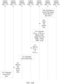
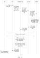
step 109 to step 111 are different. The following provides detailed description by separately using an example that the access mode is a 3GPP access mode and an example that the access mode is a non-3GPP access mode. - As shown in
FIG. 6A , it is assumed that the access mode is the 3GPP access mode, and the anchor key is ananchor key 1. Then, step 109 to step 111 may be replaced with the followingsteps 1111 to 1117. - 1111. The AMF (or the SEAF) generates a lower-layer key Kamf1 key and/or Kseaf1 key based on the following formulas:


- 1113. The AMF (or the SEAF) then generates a base station key KgNB, a 3GPP-NAS cipher key K-3GPPNASenc, and a 3GPP-NAS integrity protection key K-3GPPNASint in the 3GPP access mode based on the following formulas:


- 1115. The AMF (or the SEAF) sends the base station key KgNB to the AN. In this case, the AN correspondingly receives the base station key KgNB sent by the AMF (or the SEAF).
- 1117. The AN generates a user plane cipher key KUPenc, a user plane integrity key KUPint, a control plane cipher key KRRCenc, and a control plane integrity key KRRCint based on the base station key KgNB.
- In this embodiment of this application, the AN separately generates the user plane cipher key KUPenc, the user plane integrity key KUPint, the control plane cipher key KRRCenc, and the control plane integrity key KRRCint based on the following formulas:


Table 2 Algorithm distinguisher definition Algorithm distinguisher (Algorithm distinguisher) Value (Value) NAS-enc-alg 0x01 NAS-int-alg 0x02 RRC-enc-alg 0x03 RRC-int-alg 0x04 UP-enc-alg 0x05 UP-int-alg 0x06 - 1119. The UE generates an anchor key based on a root key, and then derives a user plane cipher key KUPenc, a user plane integrity key KUPint, a control plane cipher key KRRCenc, and a control plane integrity key KRRCint based on the anchor key.
- It may be understood that after receiving the anchor key, the AMF (or the SEAF) may not derive the Kamf1 key and/or the Kseaf1 key based on the anchor key, or then derive the base station key KgNB, the 3GPP-NAS cipher key K-3GPPNASenc, and the 3GPP-NAS integrity protection key K-3GPPNASint based on the Kamf1 key and/or the Kseaf1 key; but directly derives the base station key KgNB, the 3GPP-NAS cipher key K-3GPPNASenc, and the 3 GPP-NAS integrity protection key K-3 GPPNASint based on the anchor key.
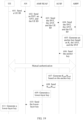
- As shown in
FIG. 6B , it is assumed that the access mode is the non-3GPP access mode, and the anchor key is ananchor key 2. Then, step 109 to step 111 may be replaced with the followingsteps 1112 to 1116. - 1112. The AMF (or the SEAF) generates a key Kamf2 and/or a key Kseaf2 based on the following formulas:


- 1114. The AMF (or the SEAF) then generates an access point key KN3IWF, a non-3GPP-NAS cipher key K-N3GPPNASenc, and a non-3GPP-NAS integrity protection key K-N3GPPNASint in the non-3GPP access mode based on the following formulas:


- 1116. The AMF (or the SEAF) sends the access point key KN3IWF to the AN. In this case, the AN correspondingly receives the access point key KN3IWF sent by the AMF (or the SEAF).
- 1118. The UE generates an anchor key based on a root key, and then derives an access point key KN3IWF based on the anchor key.
- Similarly, it may be understood that, in
step 1114, the AMF (or the SEAF) does not receive the anchor key sent by the AUSF, but the KAMF key or the KSEAF key generated by the AUSF based on the anchor key. - It may be understood that, the key generation algorithm in the embodiment shown in
FIG. 5 is not limited to the KDF algorithm. In actual application, the key generation algorithm may be another algorithm, such as a Trunc algorithm: a Trunc algorithm for truncating least significant bits, or another HASH algorithm. This is not specifically limited in this application. In addition, an independent variable of the key generation algorithm may also include another parameter, such as NSSAI, a random number, a nonce (Number used once, Nonce), a sequence number, a registration type, an non-access stratum message count (NAS Count), a security algorithm distinguisher, a security identifier, a length of SQN ⊕ AK, or a length corresponding to a parameter used for generating a key. In actual application, one or more parameters may be selected therefrom based on requirements as independent variables of the key generation algorithm. - It may be understood that after receiving the anchor key, the AMF (or the SEAF) may not derive the Kamf1 key and/or the Kseaf1 key based on the anchor key, or then derive the access point key KN3IWF, the non-3GPP-NAS cipher key K-N3GPPNASenc, and the non-3GPP-NAS integrity protection key K-N3GPPNASint based on the Kamf1 key and/or the Kseaf1 key; but directly derives the access point key KN3IWF, the non-3GPP-NAS cipher key K-N3GPPNASenc, and the non-3GPP-NAS integrity protection key K-N3GPPNASint based on the anchor key.
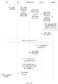
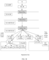
- After the anchor key generation method shown in
FIG. 5 is executed, a key architecture shown inFIG. 7 is to be generated. On the left of a separation line inFIG. 7 , there is a key architecture generated by specifically performing the process shown inFIG. 6A . On the right of the separation line inFIG. 7 , there is a key architecture generated by specifically performing the process shown inFIG. 6B . The two key architectures can be well separated. - As shown in
FIG. 8 , an embodiment of this application provides a second anchor key generation method. In this embodiment, an AUSF is the first communications device in the claims, an AMF or an SEAF is the second communications device in the claims, and an ARPF is the third communications device in the claims. The method may be implemented based on the network architectures shown inFIG. 3 andFIG. 4 , and the method includes but is not limited to the following steps: - 201. UE sends a terminal identifier to an AN. Correspondingly, the AN receives the terminal identifier sent by the UE.
- 202. The AN sends the terminal identifier and an indication identifier to the AMF (or the SEAF). Correspondingly, the AMF (or the SEAF) receives the terminal identifier and the indication identifier sent by the AN. The indication identifier includes an ANT and an SNT.
- 203. The AMF (or the SEAF) sends the terminal identifier and the indication identifier to the AUSF. Correspondingly, the AUSF receives the terminal identifier and the indication identifier sent by the AMF (or the SEAF).
- 204. The AUSF sends the terminal identifier and the indication identifier to the ARPF. Correspondingly, the ARPF receives the terminal identifier and the indication identifier sent by the AUSF.
- 205. The ARPF generates an intermediate key based on a cipher key CK, an integrity key IK, and the ANT.
- In this embodiment of this application, the ARPF may generate the intermediate key based on a key generation algorithm in the following several manners:
- In a first manner, the ARPF generates the intermediate key based on the following key generation algorithm:

- In a second manner, the ARPF generates the intermediate key based on the following key generation algorithm:

- 206. The ARPF sends the intermediate key to the AUSF. Correspondingly, the AUSF receives the intermediate key sent by the ARPF.
- 207. The AUSF generates an anchor key based on the intermediate key.
- For the first manner of generating the intermediate key in step 205, the AUSF generates the anchor key based on the intermediate key in the following manner:
- First, the AUSF generates an EMSK' based on the intermediate key:

- Then, the AUSF generates the anchor key based on the following formula:

- For the second manner of generating the intermediate key in step 205, the AUSF generates the anchor key based on the intermediate key in the following manner:
- First, the AUSF generates an EMSK' based on the intermediate key:

- Then, the AUSF generates the anchor key based on the following formula:

- Alternatively, the anchor key may be generated based on the EMSK' and another parameter, which is not limited to the indication identifier.
- It may be understood that the anchor key may also be generated based on an MSK', and using the EMSK' to generate the anchor key herein is only used as an example.
- 208. The AUSF sends the anchor key to the AMF (or the SEAF). Correspondingly, the AMF (or the SEAF) receives the anchor key sent by the AUSF.
- 209. The AMF (or the SEAF) generates a lower-layer key based on the anchor key. The lower-layer key is a key obtained by performing one or more times of derivation based on the anchor key.
- 210. The AMF (or the SEAF) sends the lower-layer key to the AN.
- 211. The UE generates an anchor key based on a root key, and then derives a lower-layer key based on the anchor key.
- As shown in
FIG. 9 , an embodiment of this application provides a third anchor key generation method. In this embodiment, an AUSF is the first communications device in the claims, an AMF or an SEAF is the second communications device in the claims, and an ARPF is the third communications device in the claims. The method may be implemented based on the network architectures shown inFIG. 3 andFIG. 4 , and the method includes but is not limited to the following steps: - 221. UE sends a terminal identifier to an AN. Correspondingly, the AN receives the terminal identifier sent by the UE.
- 222. The AN sends the terminal identifier and an indication identifier to the AMF (or the SEAF). Correspondingly, the AMF (or the SEAF) receives the terminal identifier and the indication identifier sent by the AN. The indication identifier includes an ANT and an SNT.
- 223. The AMF (or the SEAF) sends the terminal identifier and the indication identifier to the AUSF. Correspondingly, the AUSF receives the terminal identifier and the indication identifier sent by the AMF (or the SEAF).
- 224. The AUSF sends the terminal identifier and the indication identifier to the ARPF. Correspondingly, the ARPF receives the terminal identifier and the indication identifier sent by the AUSF.
- 225. The ARPF generates an intermediate key based on a cipher key CK, an integrity key IK, and the ANT.
- In this embodiment of this application, the ARPF may generate the intermediate key based on a key generation algorithm in the following several manners:
- In a first manner, the ARPF generates the intermediate key based on the following key generation algorithm:

- In a second manner, the ARPF generates the intermediate key based on the following key generation algorithm:

- where, (CK1', IK1') is the intermediate key, CK1' is the intermediate cipher key, IK1' is the intermediate integrity key, KDF is the key generation algorithm, SQN is a latest sequence number, SNT is the operator type identifier, CK is an initial cipher key, IK is an initial integrity key, AK is an anonymity key, CK=f3(RAND), IK=f4(RAND), AK=f5(RAND), RAND is a random number, f3, f4, and f5 are generation algorithms, and ⊕ means an exclusive OR operation.
- 226. The ARPF sends the intermediate key to the AUSF. Correspondingly, the AUSF receives the intermediate key sent by the ARPF.
- 227. The AUSF generates an anchor key based on the intermediate key.
- For the first manner of generating the intermediate key in step 225, the AUSF generates the anchor key based on the intermediate key in the following manner:
- First, the AUSF generates an EMSK' based on the intermediate key:

- Then, the AUSF generates the anchor key based on the following formula:

- For the second manner of generating the intermediate key in step 225, the AUSF generates the anchor key based on the intermediate key in the following manner:
- First, the AUSF generates an EMSK' based on the intermediate key:

- Then, the AUSF generates the anchor key based on the following formula:

- It may be understood that, the anchor key may be generated based on the EMSK' and another parameter, which is not limited to the indication identifier.
- It may be understood that the anchor key may also be generated based on an MSK', and using the EMSK' to generate the anchor key herein is only used as an example.
- 228. The AUSF generates a key KAMF and/or a key KSEAF based on the anchor key.
- In this embodiment of this application, the AUSF generates the key KAMF or the key KSEAF based on the following key generation algorithms:


- 229. The AUSF sends the key KAMF and/or the key KSEAF to the AMF (or the SEAF). Correspondingly, the AMF (or the SEAF) receives the key KAMF and/or the key KSEAF sent by the AUSF.
- 230. The AMF (or the SEAF) generates a lower-layer key based on the key KAMF and/or the key KSEAF. The lower-layer key is a key obtained by performing one or more times of derivation based on the key KAMF and/or the key KSEAF.
- 231. The AMF (or the SEAF) sends the lower-layer key to the AN.
- 232. The UE generates an anchor key based on a root key, and then derives a lower-layer key based on the anchor key.
- It may be understood that after generating the anchor key, the AUSF may also directly send the anchor key to the AMF, and then the AMF generates the lower-layer key based on the anchor key and sends the lower-layer key to the AN.
- After the anchor key generation method shown in
FIG. 9 is executed, a key architecture shown inFIG. 10 is to be generated. On the left of a separation line inFIG. 9 , there is a key architecture corresponding to the UE and a 3GPP network, and on the right of the separation line inFIG. 10 , there is a key architecture corresponding to the UE and a non-3GPP network. The key architectures can be well separated. - It may be understood that, for
step 227, the AUSF may further generate two keys based on the intermediate key: an MSK' and an EMSK', respectively. The MSK' and the EMSK' are different parts of a key generated by PRF'(IK2'||CK2'), for example, the MSK' is the first 512 bits, and the EMSK' is the last 512 bits. - Then, the anchor key is generated based on the MSK', namely, anchor key=KDF(MSK', ANT), as described above.
- The EMSK' is reserved by the AUSF or a key obtained after the AUSF performs derivation based on the EMSK' is reserved for subsequent extension.
- As shown in
FIG. 11A andFIG. 11B , an embodiment of this application provides a fourth anchor key generation method. In this embodiment, an AUSF is the first communications device in the claims, an SEAF is the second communications device inclaim 2, and an ARPF is the third communications device in the claims. The method may be implemented based on the network architectures shown inFIG. 3 andFIG. 4 . In addition, in this embodiment, there are m AMFs, which are named AMF_1 to AMF_m, respectively. The method includes but is not limited to the following steps: - 301. UE sends a terminal identifier to an AN. Correspondingly, the AN receives the terminal identifier sent by the UE.
- 302. The AN sends the terminal identifier and an indication identifier to the AMF_1 to the AMF_m. Correspondingly, the AMF_1 to the AMF_m receive the terminal identifier and the indication identifier sent by the AN.
- 303. The AMF_1 to the AMF_m send the terminal identifier and the indication identifier to the SEAF. Correspondingly, the SEAF receives the terminal identifier and the indication identifier sent by the AMF_1 to the AMF_m.
- 304. The SEAF sends the terminal identifier and the indication identifier to the AUSF. Correspondingly, the AUSF receives the terminal identifier and the indication identifier sent by the SEAF.
- 305. The AUSF sends the terminal identifier and the indication identifier to the ARPF. Correspondingly, the ARPF receives the terminal identifier and the indication identifier sent by the AUSF.
- 306. The ARPF generates an intermediate key based on a cipher key CK, an integrity key IK, and an ANT.
- 307. The ARPF sends the intermediate key to the AUSF. Correspondingly, the AUSF receives the intermediate key sent by the ARPF.
- 308. The AUSF generates an anchor key based on the intermediate key.
- 309. The AUSF sends the anchor key to the SEAF. Correspondingly, the SEAF receives the anchor key sent by the AUSF.
- 310. The SEAF separately generates KAMF_1 to KAMF_m based on the anchor key and identifiers of the AMF_1 to the AMF_m.
- In this embodiment of this application, the SEAF separately generates KAMF_1 to KAMF_m based on the following formulas:


- 311. The SEAF delivers KAMF_1 to KAMF_m to the AMF_1 to the AMF _m respectively. Correspondingly, the AMF_1 to the
AMF_ 2 respectively receive KAMF_1 to KAMF_m sent by the SEAF. - 312. The AMF_1 to the AMF _m separately generate lower-layer keys based on KAMF_1 to KAMF_m.
- In this embodiment of this application, the AMF_1 generates a lower-
layer key 1 based on KAMF_1; the AMF_2 generates a lower-layer key 2 based on KAMF_2; ...; and the AMF_m generates a lower-layer key m based on KAMF_m. - That the AMF_1 generates the lower-
layer key 1 based on K AMF_1 is used as an example for description in the following. - The AMF_1 generates a base station key KgNB1, a 3GPP-NAS cipher key K-3GPPNASenc1, and a 3GPP-NAS integrity protection key K-3GPPNASint1 in a 3GPP access mode based on the following formulas:


- 313. The AMFs send the lower-layer keys to the AN.
- 314. The UE generates an anchor key based on a root key, and then derives a lower-layer key based on the anchor key.
- After the anchor key generation method shown in
FIG. 11A andFIG. 11B is executed, a key architecture shown inFIG. 12 is to be generated. On the left of a separation line inFIG. 12 , there is a key architecture corresponding to the UE and a 3GPP network, and on the right of the separation line inFIG. 12 , there is a key architecture corresponding to the UE and a non-3GPP network. The key architectures can be well separated. - It may be understood that the embodiments shown in
FIG. 8 ,FIG. 9 , andFIG. 11A andFIG. 11B evolve based on the embodiment shown inFIG. 5 . For brevity, the embodiments shown inFIG. 8 ,FIG. 9 , andFIG. 11A and -
FIG. 11B describe only a part that is different from the embodiment shown inFIG. 5 . For a part that is in the embodiments shown inFIG. 8 ,FIG. 9 , andFIG. 11A andFIG. 11B and that is the same as that in the embodiment shown inFIG. 5 , refer toFIG. 5 and related content. Details are not described herein again. - As shown in
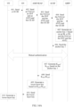
FIG. 13 , an embodiment of this application provides a fifth anchor key generation method. The method may be implemented based on the network architectures shown inFIG. 3 andFIG. 4 , and the method includes but is not limited to the following steps:
401. UE sends a terminal identifier to an AN. Correspondingly, the AN receives the terminal identifier sent by the UE. - In this embodiment of this application, the terminal identifier may be a fixed identifier, for example, a media access control (MAC) address, an Internet Protocol (IP) address, a mobile number, an international mobile equipment identity (International Mobile Equipment Identity, IMEI), an international mobile subscriber identity (IMSI), an IP multimedia private identity (IMPI), or an IP multimedia public identity (IMPU); or may be a temporarily allocated identifier, for example, a temporary mobile subscriber identity (TMSI) or a globally unique temporary UE identity (GUTI).
- It may be understood that, in addition to the terminal identifier, the UE may send, to the AN, at least one of an access network parameter, a registration type, a security parameter, a 5G network capability of the UE, and a PDU session status. The access network parameter may be a parameter related to a service network, such as a frequency of an access network, a temporary user identity, or NSSAI. The registration type may indicate that a user is performing initial registration, registration caused by a movement, a periodic registration update, or the like, so as to distinguish between user registration behaviors. The security parameter is a parameter related to authentication and integrity protection. The NSSAI is short for network slice selection assistance information. The 5G network capability of the UE may include a configuration capability that supports access to the network. The PDU session is a service connection of a PDU between the UE and a data network, and a type of the service connection may be an IP or Ethernet service connection.
- 402. The AN sends the terminal identifier and an indication identifier to an AMF (or an SEAF). Correspondingly, the AMF (or the SEAF) receives the terminal identifier and the indication identifier sent by the AN.
- In this embodiment of this application, the indication identifier is used to indicate an access mode of a terminal. In a 5G standard, the access mode of the terminal may be classified based on different classification bases. For example, the classification bases of the access mode may include an access type and an operator type. The access type may be specifically classified into a 3GPP access type, a trusted non-3GPP access type, and an untrusted non-3GPP access type. The operator type may be specifically classified into an operator type A or an operator type B. It may be understood that there may be more operator types. The operator types are merely examples herein, and are not specifically limited.
- For example, the classification bases include the access type and the operator type. Classification of the access mode may be shown in Table 1. It should be noted that the classification bases are not limited to the foregoing two types of classification bases. The classification basis of the access mode may be another type of classification basis, for example, a medium type (wired access or wireless access). This is not specifically limited herein. In addition, the classification bases are not limited to the two classification bases: the access type and the operator type. There may be one, three, four, or more classification bases of the access mode, that is, the access mode may be classified by more dimensions or fewer dimensions.
- The indication identifier may be carried in the access network parameter. The indication identifier may be any one of the following manners: The indication identifier may be a network access identifier (NAI), used to indicate both an access type and an operator type. Alternatively, the indication identifier may include an access type identifier and an operator type identifier, where the access type identifier is used to indicate the access type, and the operator type identifier is used to indicate the operator type. It may be understood that the foregoing example is merely used as an example, and does not constitute a specific limitation.
- In some possible implementations, the network access identifier may be an SN identity | an access network identity, that is, may particularly indicate a type of access of an operator, for example, WLAN access of China Unicom. The SN identity herein is defined in a 4G network, and the access network identity is defined in a non-3GPP network in 4G. It is also possible to upgrade the SN identity or access network identity mode, so that it can represent a particular access type of a particular operator.
- In some possible implementations, the access type identifier specifically indicates that the access type is a 3GPP access type, a trusted non-3GPP access type, and an untrusted non-3GPP access type. For example, the access type identifier access network type (ANT) may be directly character strings such as "3GPP network", "Trusted Non-3GPP network", and "Untrusted Non-3GPP network", or may be only character strings such as "3GPP network" and "Non-3GPP network".
- In some possible implementations, the operator type identifier may include two parts: One part is used to indicate an operator, and the other part is used to indicate a specific access type. For example, the operator type identifier may indicate LTE access of China Mobile or WLAN access of China Unicom. In specific application, a combination of the SN Identity and the Access Network Identity may be used as an operator type identifier. Alternatively, the operator type identifier may only indicate an operator, such as China Mobile, China Unicom, and China Telecom.
- In some possible implementations, it may be possible that the indication identifier is only an operator type identifier.
- In some possible implementations, it may be possible that the indication identifier is only an access type identifier.
- 403. The AMF (or the SEAF) sends the terminal identifier and the indication identifier to an AUSF. Correspondingly, the AUSF receives the terminal identifier and the indication identifier sent by the AMF (or the SEAF).
- 404. The AUSF sends the terminal identifier and the indication identifier to an ARPF. Correspondingly, the ARPF receives the terminal identifier and the indication identifier sent by the AUSF.
- 405. The ARPF generates an anchor key based on a cipher key CK, an integrity key IK, and the indication identifier.
- In this embodiment of this application, the ARPF may generate the anchor key in the following several manners:
- In a first manner, the ARPF generates the anchor key based on the following formula:

- In a second manner, the ARPF generates the anchor key based on the following formula:

- In some possible implementations, SQN may be a latest sequence number generated by an AuC, and after generating SQN, the AuC sends SQN to the ARPF. Similarly, RAND may be a random number generated by the AuC, and after generating RAND, the AuC sends RAND to the ARPF. In addition to the foregoing manner, SQN and RAND may also be generated by another communications device in the network architecture and sent to the ARPF. SQN and RAND may be even generated by the ARPF itself. This is not specifically limited herein.
- In some possible implementations, CK may be generated by the AuC based on a formula CK=f3(RAND), IK may be generated by the AuC based on a formula IK=f4(RAND), and AK may be generated by the AuC based on a formula AK=f5(RAND). In addition to the foregoing manner, CK, IK, and AK may also be generated by another communications device in the network architecture and sent to the ARPF. CK, IK, and AK may be even generated by the ARPF itself. This is not specifically limited herein.
- 406. The ARPF sends the anchor key to the AUSF. Correspondingly, the AUSF receives the anchor key sent by the ARPF.
- 407. The AUSF generates Kamf/Kseaf based on the anchor key.
- In this embodiment of this application, the AUSF generates Kamf/Kseaf based on the following formulas:


- 408. The AUSF sends Kamf/Kseaf to the AMF (or the SEAF). Correspondingly, the AMF (or the SEAF) receives Kamf/Kseaf sent by the AUSF.
- 409. The AMF (or the SEAF) generates a lower-layer key based on Kamf/Kseaf. The lower-layer key is a key obtained by performing one or more times of derivation based on the anchor key.
- 410. The AMF (or the SEAF) sends the lower-layer key to the AN.
- 411. The UE generates through derivation by itself a lower-layer key based on a CK, an IK, and an indication identifier. It may be understood that a process of deriving, by the UE, the lower-layer key is substantially similar to the foregoing process, and details are not described herein again.
- It may be understood that after generating the anchor key, the AUSF may also directly send the anchor key to the AMF, and then the AMF generates the lower-layer key based on the anchor key and sends the lower-layer key to the AN.
- It should be noted that, when access modes are different,
step 409 to step 411 are different. The following provides detailed description by separately using an example that the access mode is a 3GPP access mode and an example that the access mode is a non-3GPP access mode. - As shown in
FIG. 14A , it is assumed that the access mode is the 3GPP access mode, and the anchor key is ananchor key 1. Then, step 409 to step 411 may be replaced with the following steps 4111 to 4117. - 4111. The AMF (or the SEAF) generates a base station key KgNB, a 3GPP-NAS cipher key K-3GPPNASenc, and a 3GPP-NAS integrity protection key K-3GPPNASint based on Kamf1/Kseaf1.
- Specifically, the AMF (or the SEAF) generates the base station key KgNB, the 3GPP-NAS cipher key K-3GPPNASenc, and the 3GPP-NAS integrity protection key K-3GPPNASint in the 3GPP access mode based on the following formulas:


- 4113. The AMF (or the SEAF) sends the base station key KgNB to the AN. In this case, the AN correspondingly receives the base station key KgNB sent by the AMF (or the SEAF).
- 4115. The AN generates a user plane cipher key KUPenc, a user plane integrity key KUPint, a control plane cipher key KRRCenc, and a control plane integrity key KRRCint based on the base station key KgNB.
- In this embodiment of this application, the AN separately generates the user plane cipher key KUPenc, the user plane integrity key KUPint, the control plane cipher key KRRCenc, and the control plane integrity key KRRCint based on the following formulas:


- 4117. The UE derives an anchor key by itself based on a CK, an IK, and an indication identifier, and then derives by itself a user plane cipher key KUPenc, a user plane integrity key KUPint, a control plane cipher key KRRCenc, and a control plane integrity key KRRCint based on the anchor key.
- As shown in
FIG. 14B , it is assumed that the access mode is the non-3GPP access mode, and the anchor key is ananchor key 2. Then, step 409 to step 411 may be replaced with the following steps 4112 to 4116. - 4112. The AMF (or the SEAF) generates an access point key KN3IWF, a non-3GPP-NAS cipher key K-N3GPPNASenc, and a non-3GPP-NAS integrity protection key K-N3GPPNASint based on the anchor
key anchor key 2. - Specifically, the AMF (or the SEAF) then generates the access point key KN3IWF, the non-3GPP-NAS cipher key K-N3GPPNASenc, and the non-3GPP-NAS integrity protection key K-N3GPPNASint in the non-3GPP access mode based on the following formulas:


- 4114. The AMF (or the SEAF) sends the access point key KN3IWF to the AN. In this case, the AN correspondingly receives the access point key KN3IWF sent by the AMF (or the SEAF).
- 4116. The UE derives by itself an anchor key based on a CK, an IK, and an indication identifier, and then derives by itself an access point key KN3IWF based on the anchor key.
- It may be understood that, the key generation algorithm in the embodiment shown in
FIG. 13 is not limited to the KDF algorithm. In actual application, the key generation algorithm may be another algorithm, such as a Trunc algorithm: a Trunc algorithm for truncating least significant bits, or another HASH algorithm. This is not specifically limited in this application. In addition, an independent variable of the key generation algorithm may also include another parameter, such as NSSAI, a random number, a nonce, a sequence number, a registration type, an access stratum message count, a security algorithm distinguisher, a security identifier, a length of SQN ⊕ AK, or a length corresponding to a parameter used for generating a key. In actual application, one or more parameters may be selected therefrom based on requirements as independent variables of the key generation algorithm. - After the anchor key generation method shown in
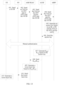
FIG. 13 is executed, a key architecture shown inFIG. 15 is to be generated. On the left of a separation line inFIG. 15 , there is a key architecture generated by specifically performing the process shown inFIG. 14A . On the right of the separation line inFIG. 15 , there is a key architecture generated by specifically performing the process shown inFIG. 14B . The two key architectures can be well separated. - As shown in
FIG. 16 , an embodiment of this application provides a sixth anchor key generation method. The method may be implemented based on the network architectures shown inFIG. 3 andFIG. 4 , and the method includes but is not limited to the following steps: - 501. UE sends a terminal identifier to an AN. Correspondingly, the AN receives the terminal identifier sent by the UE.
- In this embodiment of this application, the terminal identifier may be a fixed identifier, for example, a media access control (MAC) address, an Internet Protocol (IP) address, a mobile number, an international mobile equipment identity (International Mobile Equipment Identity, IMEI), an international mobile subscriber identity (IMSI), an IP multimedia private identity (IMPI), or an IP multimedia public identity (IMPU); or may be a temporarily allocated identifier, for example, a temporary mobile subscriber identity (TMSI) or a globally unique temporary UE identity (GUTI).
- It may be understood that, in addition to the terminal identifier, the UE may send, to the AN, at least one of an access network parameter, a registration type, a security parameter, a 5G network capability of the UE, and a PDU session status. The access network parameter may be a parameter related to a service network, such as a frequency of an access network, a temporary user identity, or NSSAI. The registration type may indicate that a user is performing initial registration, registration caused by a movement, a periodic registration update, or the like, so as to distinguish between user registration behaviors. The security parameter is a parameter related to authentication and integrity protection. The NSSAI is short for network slice selection assistance information. The 5G network capability of the UE may include a configuration capability that supports access to the network. The PDU session is a service connection of a PDU between the UE and a data network, and a type of the service connection may be an IP or Ethernet service connection.
- 502. The AN sends the terminal identifier and an indication identifier to an AMF (or an SEAF). Correspondingly, the AMF (or the SEAF) receives the terminal identifier and the indication identifier sent by the AN.
- In this embodiment of this application, the indication identifier is used to indicate an access mode of a terminal. In a 5G standard, the access mode of the terminal may be classified based on different classification bases. For example, the classification bases of the access mode may include an access type and an operator type. The access type may be specifically classified into a 3GPP access type, a trusted non-3GPP access type, and an untrusted non-3GPP access type. The operator type may be specifically classified into an operator type A or an operator type B. It may be understood that there may be more operator types. The operator types are merely examples herein, and are not specifically limited.
- For example, the classification bases include an access type and an operator type. Classification of the access mode may be shown in Table 1. It should be noted that the classification bases are not limited to the foregoing two types of classification bases. The classification basis of the access mode may be another type of classification basis, for example, a medium type (wired access or wireless access). This is not specifically limited herein. In addition, the classification bases are not limited to the two classification bases: the access type and the operator type. There may be one, three, four, or more classification bases of the access mode, that is, the access mode may be classified by more dimensions or fewer dimensions.
- The indication identifier may be carried in the access network parameter. The indication identifier may include an access type identifier and an operator type identifier, where the access type identifier is used to indicate the access type, and the operator type identifier is used to indicate the operator type. It may be understood that the foregoing example is merely used as an example, and does not constitute a specific limitation.
- In some possible implementations, the access type identifier specifically indicates that the access type is a 3GPP access type, a trusted non-3GPP access type, and an untrusted non-3GPP access type. For example, the access type identifier access network type (ANT) may be directly character strings such as "3GPP network", "Trusted Non-3GPP network", and "Untrusted Non-3GPP network", or may be only character strings such as "3GPP network" and "Non-3GPP network".
- In some possible implementations, the operator type identifier may include two parts: One part is used to indicate an operator, and the other part is used to indicate a specific access type. For example, the operator type identifier may indicate LTE access of China Mobile or WLAN access of China Unicom. In specific application, a combination of the SN Identity and the Access Network Identity may be used as an operator type identifier. Alternatively, the operator type identifier may only indicate an operator, such as China Mobile, China Unicom, and China Telecom.
- In some possible implementations, it may be possible that the indication identifier is only an operator type identifier.
- In some possible implementations, it may be possible that the indication identifier is only an access type identifier.
- 503. The AMF (or the SEAF) sends the terminal identifier and the indication identifier to an AUSF. Correspondingly, the AUSF receives the terminal identifier and the indication identifier sent by the AMF (or the SEAF).
- 504. The AUSF sends the terminal identifier and the indication identifier to an ARPF. Correspondingly, the ARPF receives the terminal identifier and the indication identifier sent by the AUSF.
- 505. The ARPF generates a shared key based on a cipher key CK, an integrity key IK, and the indication identifier.
- In this embodiment of this application, the ARPF may generate the shared key in the following several manners:
- In a first manner, the ARPF generates the shared key based on the following formula:

- In a second manner, the ARPF generates the shared key based on the following formula:

- In some possible implementations, SQN may be a latest sequence number generated by an AuC, and after generating SQN, the AuC sends SQN to the ARPF. Similarly, RAND may be a random number generated by the AuC, and after generating RAND, the AuC sends RAND to the ARPF. In addition to the foregoing manner, SQN and RAND may also be generated by another communications device in the network architecture and sent to the ARPF. SQN and RAND may be even generated by the ARPF itself. This is not specifically limited herein.
- In some possible implementations, CK may be generated by the AuC based on a formula CK=f3(RAND), IK may be generated by the AuC based on a formula IK=f4(RAND), and AK may be generated by the AuC based on a formula AK=f5(RAND). In addition to the foregoing manner, CK, IK, and AK may also be generated by another communications device in the network architecture and sent to the ARPF. CK, IK, and AK may be even generated by the ARPF itself. This is not specifically limited herein.
- 506. The ARPF sends the shared key to the AUSF. Correspondingly, the AUSF receives the shared key sent by the ARPF.
- 507. The AUSF sends the shared key to the AMF (or the SEAF). Correspondingly, the AMF (or the SEAF) receives the shared key sent by the AUSF.
- 508. The AMF (or the SEAF) generates an anchor key based on the shared key.
- For the first manner of generating the shared key in
step 505, the AMF generates the anchor key based on the shared key in the following manner:
- For the second manner of generating the shared key in
step 505, the AMF generates the anchor key based on the shared key in the following manner:
- 509. The AMF (or the SEAF) generates a lower-layer key based on the anchor key. The lower-layer key is a key obtained by performing one or more times of derivation based on the anchor key.
- It may be understood that a process in which the AMF (or the SEAF) generates the lower-layer key based on a key Kamf/a key Kseaf is basically the same as the processes shown in
FIG. 6A andFIG. 6B . For details, refer toFIG. 6A andFIG. 6B and related content. Details are not described herein again. - 510. The AMF (or the SEAF) sends the lower-layer key to the AN.
- 511. The UE generates a lower-layer key based on an AK, an IK, an SNT, and an ANT. It may be understood that a process of deriving, by the UE, the lower-layer key is substantially similar to the foregoing process, and details are not described herein again.
- It should be noted that, when access modes are different,
step 509 to step 511 are different. The following provides detailed description by separately using an example that the access mode is a 3GPP access mode and an example that the access mode is a non-3GPP access mode. - As shown in
FIG. 17A , it is assumed that the access mode is the 3GPP access mode, and the anchor key is ananchor key 1. Then, step 509 to step 511 may be replaced with the followingsteps 5111 to 5117. - 5111. The AMF (or the SEAF) generates a base station key KgNB, a 3GPP-NAS cipher key K-3GPPNASenc, and a 3GPP-NAS integrity protection key K-3GPPNASint based on the
anchor key 1. - Specifically, the AMF (or the SEAF) generates the base station key KgNB, the 3GPP-NAS cipher key K-3GPPNASenc, and the 3GPP-NAS integrity protection key K-3GPPNASint in the 3GPP access mode based on the following formulas:


- 5113. The AMF (or the SEAF) sends the base station key KgNB to the AN. In this case, the AN correspondingly receives the base station key KgNB sent by the AMF (or the SEAF).
- 5115. The AN generates a user plane cipher key KUPenc, a user plane integrity key KUPint, a control plane cipher key KRRCenc, and a control plane integrity key KRRCint based on the base station key KgNB.
- In this embodiment of this application, the AN separately generates the user plane cipher key KUPenc, the user plane integrity key KUPint, the control plane cipher key KRRCenc, and the control plane integrity key KRRCint based on the following formulas:


- 5117. The UE generates an anchor key by itself based on an AK, an IK, an SNT, and an ANT, and then derives by itself a user plane cipher key KUPenc, a user plane integrity key KUPint, a control plane cipher key KRRCenc, and a control plane integrity key KRRCint based on the anchor key.
- As shown in
FIG. 17B , it is assumed that the access mode is the non-3GPP access mode, and the anchor key is ananchor key 2. Then, step 509 to step 511 may be replaced with the following steps 5112 to 5116. - 5112. The AMF (or the SEAF) generates an access point key KN3IWF, a non-3GPP-NAS cipher key K-N3GPPNASenc, and a non-3GPP-NAS integrity protection key K-N3GPPNASint based on the
anchor key 2. - Specifically, the AMF (or the SEAF) then generates the access point key KN3IWF, the non-3GPP-NAS cipher key K-N3GPPNASenc, and the non-3GPP-NAS integrity protection key K-N3GPPNASint in the non-3GPP access mode based on the following formulas:


- 5114. The AMF (or the SEAF) sends the access point key KN3IWF to the AN. In this case, the AN correspondingly receives the access point key KN3IWF sent by the AMF (or the SEAF).
- 5116. The UE generates by itself an anchor key based on an AK, an IK, an SNT, and an ANT, and then derives by itself an access point key KN3IWF based on the anchor key.
- It may be understood that, the key generation algorithm in the embodiment shown in
FIG. 16 is not limited to the KDF algorithm. In actual application, the key generation algorithm may be another algorithm, such as a Trunc algorithm: a Trunc algorithm for truncating least significant bits, or another HASH algorithm. This is not specifically limited in this application. In addition, an independent variable of the key generation algorithm may also include another parameter, such as NSSAI, a random number, a nonce, a sequence number, a registration type, an access stratum message count, a security algorithm distinguisher, a security identifier, a length of SQN ⊕ AK, or a length corresponding to a parameter used for generating a key. In actual application, one or more parameters may be selected therefrom based on requirements as independent variables of the key generation algorithm. - After the anchor key generation method shown in
FIG. 16 is executed, a key architecture shown inFIG. 18 is to be generated. On the left of a separation line inFIG. 18 , there is a key architecture generated by specifically performing the process shown inFIG. 17A . On the right of the separation line inFIG. 18 , there is a key architecture generated by specifically performing the process shown inFIG. 17B . The two key architectures can be well separated. - As shown in
FIG. 19 , an embodiment of this application provides a seventh anchor key generation method. The method may be implemented based on the network architectures shown inFIG. 3 andFIG. 4 , and the method includes but is not limited to the following steps:
601. UE sends a terminal identifier to an AN. Correspondingly, the AN receives the terminal identifier sent by the UE. - In this embodiment of this application, the terminal identifier may be a fixed identifier, for example, a media access control ( MAC) address, an Internet Protocol (IP) address, a mobile number, an international mobile equipment identity (International Mobile Equipment Identity, IMEI), an international mobile subscriber identity (IMSI), an IP multimedia private identity IMPI), or an IP multimedia public identity (IMPU); or may be a temporarily allocated identifier, for example, a temporary mobile subscriber identity (TMSI) or a globally unique temporary UE identity (GUTI).
- It may be understood that, in addition to the terminal identifier, the UE may send, to the AN, at least one of an access network parameter, a registration type, a security parameter, a 5G network capability of the UE, and a PDU session status. The access network parameter may be a parameter related to a service network, such as a frequency of an access network, a temporary user identity, or NSSAI. The registration type may indicate that a user is performing initial registration, registration caused by a movement, a periodic registration update, or the like, so as to distinguish between user registration behaviors. The security parameter is a parameter related to authentication and integrity protection. The NSSAI is short for network slice selection assistance information. The 5G network capability of the UE may include a configuration capability that supports access to the network. The PDU session is a service connection of a PDU between the UE and a data network, and a type of the service connection may be an IP or Ethernet service connection.
- 602. The AN sends the terminal identifier and an indication identifier to an AMF (or an SEAF). Correspondingly, the AMF (or the SEAF) receives the terminal identifier and the indication identifier sent by the AN.
- In this embodiment of this application, the indication identifier is used to indicate an access mode of a terminal. In a 5G standard, the access mode of the terminal may be classified based on different classification bases. For example, the classification bases of the access mode may include an access type and an operator type. The access type may be specifically classified into a 3GPP access type, a trusted non-3GPP access type, and an untrusted non-3GPP access type. The operator type may be specifically classified into an operator type A or an operator type B. It may be understood that there may be more operator types. The operator types are merely examples herein, and are not specifically limited.
- For example, the classification bases include an access type and an operator type. Classification of the access mode may be shown in Table 1. It should be noted that the classification bases are not limited to the foregoing two types of classification bases. The classification basis of the access mode may be another type of classification basis, for example, a medium type (wired access or wireless access). This is not specifically limited herein. In addition, the classification bases are not limited to the two classification bases: the access type and the operator type. There may be one, three, four, or more classification bases of the access mode, that is, the access mode may be classified by more dimensions or fewer dimensions.
- The indication identifier may be carried in the access network parameter. The indication identifier may include an access type identifier and an operator type identifier, where the access type identifier is used to indicate the access type, and the operator type identifier is used to indicate the operator type. It may be understood that the foregoing example is merely used as an example, and does not constitute a specific limitation.
- In some possible implementations, the access type identifier specifically indicates that the access type is a 3GPP access type, a trusted non-3GPP access type, and an untrusted non-3GPP access type. For example, the access type identifier access network type (ANT) may be directly character strings such as "3GPP network", "Trusted Non-3GPP network", and "Untrusted Non-3GPP network", or may be only character strings such as "3GPP network" and "Non-3GPP network".
- In some possible implementations, the operator type identifier may include two parts: One part is used to indicate an operator, and the other part is used to indicate a specific access type. For example, the operator type identifier may indicate LTE access of China Mobile or WLAN access of China Unicom. In specific application, a combination of the SN Identity and the Access Network Identity may be used as an operator type identifier. Alternatively, the operator type identifier may only indicate an operator, such as China Mobile, China Unicom, and China Telecom.
- In some possible implementations, it may be possible that the indication identifier is only an operator type identifier.
- In some possible implementations, it may be possible that the indication identifier is only an access type identifier.
- 603. The AMF (or the SEAF) sends the terminal identifier and the indication identifier to an AUSF. Correspondingly, the AUSF receives the terminal identifier and the indication identifier sent by the AMF (or the SEAF).
- 604. The AUSF sends the terminal identifier and the indication identifier to an ARPF. Correspondingly, the ARPF receives the terminal identifier and the indication identifier sent by the AUSF.
- 605. The ARPF generates an anchor key based on a root key K and the indication identifier.
- In this embodiment of this application, the ARPF may generate the anchor key based on a key generation algorithm in the following several manners:
- In a first manner, when the indication identifier is an NAI, the ARPF generates the anchor key based on the following key generation algorithm:

- In a second manner, when the indication identifier includes an access type identifier and an operator type identifier, the ARPF generates the anchor key anchor key based on the following key generation algorithm:

- In some possible implementations, SQN may be a latest sequence number generated by an AuC, and after generating SQN, the AuC sends SQN to the ARPF. Similarly, RAND may be a random number generated by the AuC, and after generating RAND, the AuC sends RAND to the ARPF. In addition to the foregoing manner, SQN and RAND may also be generated by another communications device in the network architecture and sent to the ARPF. SQN and RAND may be even generated by the ARPF itself. This is not specifically limited herein.
- In some possible implementations, AK may be generated by the AuC based on a formula AK=f5(RAND). In addition to the foregoing manner, AK may also be generated by another communications device in the network architecture and sent to the ARPF. AK may be even generated by the ARPF itself. This is not specifically limited herein.
- 606. The ARPF sends the anchor key to the AUSF. Correspondingly, the AUSF receives the anchor key sent by the ARPF.
- 607. The AUSF generates a key Kamf and/or a key Kseaf based on the anchor key.
- In this embodiment of this application, the AUSF generates the key Kamf and/or the key Kseaf based on the following formulas:


- 608. The AUSF sends the key Kamf/the key Kseaf to the AMF/the SEAF. Correspondingly, the AMF/the SEAF receives the key Kamf/the key Kseaf sent by the AUSF.
- 609. The AMF (or the SEAF) generates a lower-layer key based on the key Kamf/the key Kseaf. The lower-layer key is a key obtained by performing one or more times of derivation based on the anchor key.
- It may be understood that a process in which the AMF (or the SEAF) generates the lower-layer key based on the key Kamf/the key Kseaf is basically the same as the processes shown in FIG. 12A and FIG. 12B. For details, refer to FIG. 12A and FIG. 12B and related content. Details are not described herein again.
- 610. The AMF (or the SEAF) sends the lower-layer key to the AN.
- 611. The UE generates a lower-layer key based on K, an SNT, and an ANT. It may be understood that a process of deriving, by the UE, the lower-layer key is substantially similar to the foregoing process, and details are not described herein again.
- It may be understood that after generating the anchor key, the AUSF may also directly send the anchor key to the AMF, and then the AMF generates the lower-layer key based on the anchor key and sends the lower-layer key to the AN.
- It may be understood that, the key generation algorithm in the embodiment shown in
FIG. 19 is not limited to the KDF algorithm. In actual application, the key generation algorithm may be another algorithm, such as a Trunc algorithm: a Trunc algorithm for truncating least significant bits, or another HASH algorithm. This is not specifically limited in this application. In addition, an independent variable of the key generation algorithm may also include another parameter, such as NSSAI, a random number, a nonce, a sequence number, a registration type, an access stratum message count, a security algorithm distinguisher, a security identifier, a length of SQN ⊕ AK, or a length corresponding to a parameter used for generating a key. In actual application, one or more parameters may be selected therefrom based on requirements as independent variables of the key generation algorithm. - After the anchor key generation method shown in
FIG. 19 is executed, a key architecture shown inFIG. 20 is to be generated. On the left of a separation line inFIG. 20 , there is a key architecture generated by specifically performing the process of the 3GPP access mode. On the right of the separation line inFIG. 20 , there is a key architecture generated by specifically performing the process of the non-3GPP access mode. The two key architectures can be well separated. - In another embodiment of the present invention, an implementation of reserving a key on an AUSF is disclosed. The reserved key may be Kleft for short.
- Specifically, it should be noted that the AUSF sends an anchor key to a second communications device SEAF, and in a possible deployment scenario, the SEAF is a security network element of a service network, and the AUSF is a security network element of a home network. Especially in a roaming scenario, if authentication occurs between UE and a security network element of the home network, the UE and the AUSF may generate a final protection key based on a reserved key obtained after the authentication, so as to implement end-to-end security protection or higher security protection between the UE and the home network.
- It should be noted that the reserved key may be generated by an ARPF, and then sent to the AUSF, or the reserved key may be directly generated by the AUSF.
- Method 1: The ARPF may generate the reserved key Kleft based on a parameter such as an IK, a CK, an SQN, an AK, a service network identifier, a key characteristic identifier, a RAND, or a nonce.
- The SQN is a latest sequence number, the CK is an initial cipher key, the IK is an initial integrity key, the AK is an anonymity key, and both the RAND and the Nonce may be considered as random numbers. The key characteristic identifier may be a character string such as KEYLEFT, AUSFKEY, KEYAUSF, KEYSEAF, and SEAFKEY
- A subsequently related generation function KDF may also be a pseudo random function (pseudo random function, PRF), or the like. For details, refer to the definition in Section 3.4.1 in RFC5448.
- For example, Kleft=KDF(IK, CK, SQN⊕AK, optional parameter), and KDF is a key generation algorithm.
- The optional parameter is one or more of an authentication method name, the service network identifier, the key characteristic identifier, the RAND, and the nonce.
- The authentication method name may be an identifier of an identifier authentication method such as 'EAP-AKA", '5G-EAP', or'EPS-AKA*'.
- For EPS-AKA*, the ARPF may generate Kleft based on parameters such as Kasme∗, the authentication method name, the service network identifier, a network type identifier, the key characteristic identifier, the RAND, and the nonce.
- Kasme∗ is a key similar to Kasme in 4G LTE.
- For example, Kleft=KDF(Kasme∗, first parameter group).
- The first parameter group is one or more of the authentication method name, the service network identifier, the network type identifier, the key characteristic identifier, the RAND, and the nonce.
- It should be noted that a process of generating the reserved key described in
Method 1 may be separately combined with the methods described inFIG. 5 ,FIG. 8 ,FIG. 9 ,FIG. 11A andFIG. 11B ,FIG. 13 , andFIG. 16 . - Method 2: For EAP-AKA', the ARPF may generate Kleft based on one or more of parameters such as an IK', a CK', the authentication method name, the service network identifier, the key characteristic identifier, an AUSF ID, the RAND, and the nonce.
- For example, Kleft=KDF(IK', CK', service network identifier, key characteristic identifier, second parameter group).
- The second parameter group is one or more of the authentication method name, the AUSF ID, the RAND, and the nonce.
- It should be noted that, alternatively, the ARPF may send the IK' and the CK' to the AUSF, and the AUSF generates the Kleft.
- It should be noted that a process of generating the reserved key described in
Method 2 may be separately combined with the methods described inFIG. 5 ,FIG. 8 ,FIG. 9 , andFIG. 11A andFIG 11B . - Method 3: The AUSF may generate Kleft based on parameters such as an EMSK and an MSK. The EMSK is short for extended master session key. Refer to RFC5448. The MSK is short for master session key. Refer to RFC5448.
- For example, Kleft=trunc (EMSK or MSK). This formula means that some bits of the EMSK or the MSK are directly truncated as Kleft, and trunc is used to truncate a value. For example, trunc(number) indicates truncating a number; trunc(date) indicates truncating a date. Format: TRUNC(n1, n2), where n1 indicates a to-be-truncated number, n2 indicates truncating to which digit, n2 may be a negative number, meaning truncating to a digit on the left of a decimal point. It should be noted that TRUNC truncation is not rounding off.
- For example, Kleft=KDF(EMSK or MSK, key characteristic identifier, third parameter group).
- The third parameter group is one or more of the service network identifier, the authentication method name, the random number, and the like.
- For example, Kleft may also be understood as the EMSK.
- It should be noted that a process of generating the reserved key described in
Method 3 may be separately combined with the methods described inFIG. 8 ,FIG. 9 , andFIG. 11A andFIG. 11B . - It may be understood that when Kleft exists, the anchor key may be a key generated based on Kleft.
- Specifically, the anchor key may be generated based on a parameter such as Kleft, the service network identifier, the key characteristic identifier, the RAND, or the nonce.
- In addition, in another embodiment of the present invention,
step 1114 inFIG. 6B , step 4112 inFIG. 14B , and step 5112 inFIG. 17B may be replaced with the following: - The AMF (or the SEAF) generates an access point key KN3IWF in a non-3GPP access mode based on parameters such as Kamf2, Kseaf2, NAS Count2, a NAS connection differentiation identifier, and an N3IWF identifier.
- For example,

- The formula: KN3IWF=KDF(Kamf2 and/or Kseaf2, NAS Count2) includes three possibilities:
- 1:

- 2:

- 3:

-
FIG. 21 shows a schematic structural diagram of a communications device. In this implementation, the communications device includes a receivingmodule 710, a sendingmodule 720, and ageneration module 730. The following provides detailed description. - The receiving
module 710 is configured to receive an indication identifier sent by a second communications device, where the indication identifier is used to indicate an access mode of a terminal. - The sending
module 720 is configured to send the indication identifier to a third communications device. - The receiving
module 710 is configured to receive an intermediate key returned by the third communications device, where the intermediate key is generated based on the indication identifier. - The
generation module 730 is configured to generate an anchor key based on the intermediate key, where the anchor key is corresponding to the access mode of the terminal. - The sending
module 720 is configured to send the anchor key to the second communications device, so that the second communications device derives a lower-layer key for the access mode based on the anchor key. - It should be noted that, for content not mentioned in the embodiment in
FIG. 21 and specific implementations of each function unit, refer toFIG. 5 to FIG. 10 and related content, and details are not described herein again. - Based on a same inventive concept, an embodiment of the present invention further provides an apparatus (shown in
FIG. 22 ). The apparatus is configured to implement the methods described in the foregoing embodiments ofFIG. 5 to FIG. 12 . As shown inFIG. 22 , anapparatus 800 includes atransmitter 803, areceiver 804, amemory 802, and aprocessor 801 coupled to the memory 802 (there may be one ormore processors 801, and one processor is used as an example inFIG. 20 ). Thetransmitter 803, thereceiver 804, thememory 802, and theprocessor 801 may be connected to each other by using a bus or in another manner (using abus 805 to implement connection is used as an example inFIG. 22 ). Thetransmitter 803 is configured to send data to the outside, and thereceiver 804 is configured to receive data from the outside. Thememory 802 is configured to store program code, and theprocessor 801 is configured to invoke and run the program code stored in thememory 802. - The
receiver 804 receives an indication identifier sent by a second communications device, where the indication identifier is used to indicate an access mode of a terminal. - The
transmitter 803 sends the indication identifier to a third communications device. Thereceiver 804 receives an intermediate key returned by the third communications device, where the intermediate key is generated based on the indication identifier. - The
processor 801 generates an anchor key based on the intermediate key, where the anchor key is corresponding to the access mode of the terminal. - The
transmitter 803 sends the anchor key to the second communications device, so that the second communications device derives a lower-layer key for the access mode based on the anchor key. - In some possible implementations, the access mode is distinguished based on at least one of an access type and an operator type.
- In some possible implementations, the
processor 801 generates the anchor key based on the following formula:
- The
processor 801 may generate the intermediate key based on at least the following two manners: - When the indication identifier includes an access type identifier and an operator type identifier, the intermediate key is generated by the
processor 801 based on the following formula:
- When the indication identifier is an NAI, the intermediate key is generated by the
processor 801 based on the following formula:
- In some possible implementations, the
processor 801 generates the intermediate key based on the following formula:
- The
processor 801 generates an EMSK' based on the following formula:
- The
processor 801 generates the anchor key based on the following formula:
- In some possible implementations, the
processor 801 generates the intermediate key based on the following formula:
- The
processor 801 generates an EMSK' based on the following formula:
- The
processor 801 generates the anchor key based on the following formula:
- A person skilled in the art should understand that the embodiments of the present invention may be provided as a method, a system, or a computer program product. Therefore, embodiments of the present invention may be in a form of hardware, software, or with a combination of software and hardware. Moreover, the present invention may use a form of a computer program product that is implemented on one or more computer-usable storage media (including but not limited to a disk memory, a CD-ROM, an optical memory, and the like) that include computer-usable program code.
- The embodiments of the present invention is described with reference to the flowcharts and/or block diagrams of the method, the device (system), and the computer program product. It should be understood that computer program instructions may be used to implement each process and/or each block in the flowcharts and/or the block diagrams and a combination of a process and/or a block in the flowcharts and/or the block diagrams. These computer program instructions may be provided for a general-purpose computer, a dedicated computer, an embedded processor, or a processor of any other programmable data processing device to generate a machine, so that the instructions executed by a computer or a processor of any other programmable data processing device generate an apparatus for implementing a specific function in one or more processes in the flowcharts and/or in one or more blocks in the block diagrams.
- These computer program instructions may also be stored in a computer readable memory that can instruct the computer or any other programmable data processing device to work in a specific manner, so that the instructions stored in the computer readable memory generate an artifact that includes an instruction apparatus. The instruction apparatus implements a specific function in one or more processes in the flowcharts and/or in one or more blocks in the block diagrams.
- These computer program instructions may also be loaded onto a computer or another programmable data processing device, so that a series of operations and steps are performed on the computer or the another programmable device, thereby generating computer-implemented processing. Therefore, the instructions executed on the computer or the another programmable device provide steps for implementing a specific function in one or more processes in the flowcharts and/or in one or more blocks in the block diagrams.
- Obviously, a person skilled in the art can make various modifications and variations to the present invention without departing from the spirit and scope of the present invention. The present invention is intended to cover these modifications and variations provided that they fall within the scope of protection defined by the following claims and their equivalent technologies.
- Further embodiments of the present invention are provided in the following. It should be noted that the numbering used in the following section does not necessarily need to comply with the numbering used in the previous sections.
-
Embodiment 1. An anchor key generation system, wherein the system comprises an authentication server, a security anchor, and a unified data management network element; - the unified data management network element is configured to generate an intermediate key based on a cipher key, an integrity key, and an indication identifier of an operator network accessed by a terminal, and send the intermediate key to the authentication server;
- the authentication server is configured to receive the intermediate key returned by the unified data management network element;
- the authentication server is further configured to obtain an anchor key based on the intermediate key;
- the authentication server is configured to send the anchor key to the security anchor;
- the security anchor is configured to obtain a derivation key based on the anchor key; and obtain a key of access node of a non-3GPP access mode the based on the derivation key when the access mode is a non-3GPP access mode.
-
Embodiment 2. The system according toembodiment 1, wherein the authentication server is configured to: generate an extended master session key EMSK' based on the intermediate key, and obtain the anchor key based on the EMSK'. -
Embodiment 3. The system according toembodiment 2, wherein the authentication server is configured to: generate the anchor key based on a type identifier of an operator accessed by a terminal and the EMSK'. -
Embodiment 4. The system according to any one ofembodiments 1 to 3, wherein the security anchor is further configured to: determine the key of access node of a non-3GPP access mode the based on an uplink count value corresponding to a non-access stratum message and the derivation key. -
Embodiment 5. The system according to any one ofembodiments 1 to 4, wherein the security anchor is further configured to: obtain a base station key based on the derivation key when the access mode is a 3GPP access mode. -
Embodiment 6. The system according to any one ofembodiments 1 to 5, wherein the security anchor is further configured to: obtain a derivation key based on the anchor key and an identity of the security anchor. - Embodiment 7. The system according to any one of
embodiments 1 to 6, wherein the generating an intermediate key based on a cipher key CK, an integrity key IK, and an indication identifier of an operator network accessed by a terminal comprises:
- Embodiment 8. A derivation key generation method, wherein the method comprises:
- generating, by a terminal, an intermediate key based on an indication identifier of an operator accessed by the terminal, a cipher key, and an integrity key;
- obtaining, by the terminal, an anchor key Kseaf based on the intermediate key;
- obtaining, by the terminal, a derivation key Kamf based on the anchor key; and
- when a type of accessing a network by the terminal is a non-3GPP access type, obtaining, by the terminal, a key of access node of the non-3GPP access mode based on the Kamf.
- Embodiment 9. The method according to embodiment 8, wherein the obtaining, by the terminal, a key of access node of the non-3GPP access mode based on Kamf comprises:
obtaining, by the terminal, the key of access node of the non-3GPP access mode based on an uplink count value of a non-access stratum message and the Kamf. - Embodiment 10. The method according to embodiment 8 or 9, wherein the obtaining, by the terminal, an anchor key based on the intermediate key comprises:
generating, by the terminal, an extended master session key EMSK' based on the intermediate key, and obtaining the anchor key based on the EMSK'. - Embodiment 11. The method according to embodiment 10, wherein the obtaining the anchor key based on the EMSK' comprises:
generating, by the terminal, the anchor key based on the EMSK' and the indication identifier of the operator accessed by the terminal. - Embodiment 12. The method according to any one of embodiments 8 to 11, wherein the method further comprises:
when the type of accessing a network by the terminal is a 3GPP access type, obtaining, by the terminal, a base station key KgNB based on Kamf. - Embodiment 13. The method according to any one of embodiments 8 to 12, wherein the obtaining, by the terminal, a derivation key Kamf based on the anchor key comprising:
obtaining, by the terminal, an identity of access and management network element and a derivation key Kamf based on the anchor key. - Embodiment 14. A terminal, comprising a processor and a memory, wherein the memory stores program code, and when the program code is executed, the processor performs the following operations:
- generating an intermediate key based on an indication identifier of an operator accessed by the terminal, a cipher key, and an integrity key;
- obtaining an anchor key Kseaf based on the intermediate key;
- obtaining a derivation key Kamf based on the anchor key; and
- when a type of accessing a network by the terminal is a non-3GPP access type, obtaining an access point key of the non-3GPP access mode based on Kamf.
- Embodiment 15. The terminal according to embodiment 14, wherein the obtaining a key of access node of the non-3GPP access mode based on Kamf comprises:
obtaining the key of access node of the non-3GPP access mode based on an uplink count value of a non-access stratum message and Kamf. - Embodiment 16. The terminal according to embodiment 14 or 15, wherein the obtaining an anchor key based on the intermediate key comprises:
generating an extended master session key EMSK' based on the intermediate key, and obtaining the anchor key based on the EMSK'. - Embodiment 17. The terminal according to embodiment 16, wherein the obtaining the anchor key based on the EMSK' comprises:
generating the anchor key based on the EMSK' and the indication identifier of the operator accessed by the terminal. - Embodiment 18. The terminal according to any one of embodiments 14 to 17, wherein the processor is further configured to perform the following operation:
when the type of accessing a network by the terminal is a 3GPP access type, obtaining, by the terminal, a base station key KgNB based on Kamf. - Embodiment 19. The terminal according to any one of embodiments 14 to 18, wherein the obtaining a derivation key based on the anchor key comprising:
obtaining an identity of access and management network element and a derivation key based on the anchor key.
Claims (11)
- A method for generating a key in a communication system, comprising:generating, by a user equipment, a cipher key, CK, and an integrity key, IK, based on a root key;generating, by the user equipment, an intermediate key based on the CK, the IK and an operator type identifier;generating, by the user equipment, an anchor key based on the intermediate key;generating, by the user equipment, a key, Kamf, based on the anchor key; andderiving, by the user equipment, a base station key based on the Kamf in a 3GPP access mode; andbased on the base station key, generating, by the user equipment, a user plane cipher key for performing encryption protection on user plane data, a user plane integrity key for performing integrity protection on the user plane data, a control plane cipher key for performing encryption protection on control plane data, and a control plane integrity key for performing integrity protection on the control plane data.
- The method according to claim 1, wherein the operator type identifier comprises a service network, SN, identity and an access network, AN, identity of an access network accessed by the user equipment.
- The method according to claim 1, wherein the operator type identifier indicates an operator.
- The method according to any one of claims 1 to 3, further comprising:generating, by the user equipment, a 3GPP-NAS cipher key, and a 3GPP-NAS integrity protection key based on the Kamf in the 3GPP access mode.
- The method according to any one of claims 1 to 4, wherein the generating Kamf based on the anchor key, comprises:
generating the Kamf based on the following formula:
- A user equipment, comprising:a processor; anda memory storing computer program instructions which when executed by the processor, cause the processor to implement:generating a cipher key, CK, and an integrity key, IK, based on a root key;generating an intermediate key based on the CK, the IK and an operator type identifier;generating an anchor key based on the intermediate key;generating a key, Kamf, based on the anchor key; andderiving a base station key based on the Kamf in an 3GPP access mode; andbased on the base station key, generating a user plane cipher key for performing encryption protection on user plane data, a user plane integrity key for performing integrity protection on the user plane data, a control plane cipher key for performing encryption protection on control plane data, and a control plane integrity key for performing integrity protection on the control plane data.
- The user equipment according to claim 6, wherein the operator type identifier comprises a service network, SN, identity and an access network, AN, identity of an access network accessed by the user equipment.
- The user equipment according to claim 6, wherein the operator type identifier indicates an operator.
- The user equipment according to any one of claims 6 to 8, wherein the processor is further caused to implement:
generating a 3GPP-NAS cipher key, and a 3GPP-NAS integrity protection key based on the Kamf in the 3GPP access mode. - The user equipment according to any one of claims 6 to 9, wherein the processor is specially caused to implement:
generating the Kamf based on the following formula:
- A computer readable storage medium, wherein the computer readable storage medium stores instructions which when executed by a processor in a user equipment, cause the processor to implement the method of any one of claims 1 to 5.
Applications Claiming Priority (4)
| Application Number | Priority Date | Filing Date | Title |
|---|---|---|---|
| CN201710313519 | 2017-05-05 | ||
| CN201710908017.0A CN108809635A (en) | 2017-05-05 | 2017-09-29 | Anchor key generation method, equipment and system |
| EP18795025.8A EP3531732B1 (en) | 2017-05-05 | 2018-04-25 | Anchor key generation method, device and system |
| PCT/CN2018/084416 WO2018201946A1 (en) | 2017-05-05 | 2018-04-25 | Anchor key generation method, device and system |
Related Parent Applications (2)
| Application Number | Title | Priority Date | Filing Date |
|---|---|---|---|
| EP18795025.8A Division EP3531732B1 (en) | 2017-05-05 | 2018-04-25 | Anchor key generation method, device and system |
| EP18795025.8A Division-Into EP3531732B1 (en) | 2017-05-05 | 2018-04-25 | Anchor key generation method, device and system |
Publications (1)
| Publication Number | Publication Date |
|---|---|
| EP4203533A1 true EP4203533A1 (en) | 2023-06-28 |
Family
ID=64094528
Family Applications (2)
| Application Number | Title | Priority Date | Filing Date |
|---|---|---|---|
| EP18795025.8A Active EP3531732B1 (en) | 2017-05-05 | 2018-04-25 | Anchor key generation method, device and system |
| EP22210348.3A Pending EP4203533A1 (en) | 2017-05-05 | 2018-04-25 | Anchor key generation method, device, and system |
Family Applications Before (1)
| Application Number | Title | Priority Date | Filing Date |
|---|---|---|---|
| EP18795025.8A Active EP3531732B1 (en) | 2017-05-05 | 2018-04-25 | Anchor key generation method, device and system |
Country Status (7)
| Country | Link |
|---|---|
| US (3) | US11012855B2 (en) |
| EP (2) | EP3531732B1 (en) |
| JP (1) | JP6924848B2 (en) |
| KR (1) | KR102245688B1 (en) |
| CN (4) | CN108810890B (en) |
| BR (1) | BR112019022792B1 (en) |
| WO (1) | WO2018201946A1 (en) |
Families Citing this family (11)
| Publication number | Priority date | Publication date | Assignee | Title |
|---|---|---|---|---|
| US11849319B2 (en) * | 2017-07-28 | 2023-12-19 | Telefonaktiebolaget Lm Ericsson (Publ) | Methods providing non-3GPP access using access network keys and related wireless terminals and network nodes |
| CN111404666A (en) * | 2019-01-02 | 2020-07-10 | 中国移动通信有限公司研究院 | Key generation method, terminal equipment and network equipment |
| EP3684088A1 (en) * | 2019-01-18 | 2020-07-22 | Thales Dis France SA | A method for authentication a secure element cooperating with a mobile equipment within a terminal in a telecommunication network |
| WO2020208294A1 (en) * | 2019-04-11 | 2020-10-15 | Nokia Technologies Oy | Establishing secure communication paths to multipath connection server with initial connection over public network |
| WO2020254204A1 (en) * | 2019-06-17 | 2020-12-24 | Telefonaktiebolaget Lm Ericsson (Publ) | Handling of nas container in registration request at amf re-allocation |
| CN110830985B (en) * | 2019-11-11 | 2022-04-29 | 重庆邮电大学 | 5G lightweight terminal access authentication method based on trust mechanism |
| CN113162758B (en) * | 2020-01-23 | 2023-09-19 | 中国移动通信有限公司研究院 | Key generation method and device |
| MX2022010227A (en) * | 2020-02-21 | 2022-09-19 | Ericsson Telefon Ab L M | Authentication server function selection in authentication and key management. |
| CN113873492B (en) * | 2020-06-15 | 2022-12-30 | 华为技术有限公司 | Communication method and related device |
| CN116325840A (en) * | 2020-09-30 | 2023-06-23 | 华为技术有限公司 | Key derivation method, device and system thereof |
| CN112738799A (en) * | 2020-12-29 | 2021-04-30 | 中盈优创资讯科技有限公司 | Method for realizing data security transmission based on strategy |
Family Cites Families (19)
| Publication number | Priority date | Publication date | Assignee | Title |
|---|---|---|---|---|
| WO2008038949A1 (en) * | 2006-09-28 | 2008-04-03 | Samsung Electronics Co., Ltd. | A system and method of providing user equipment initiated and assisted backward handover in heterogeneous wireless networks |
| JP4390842B1 (en) * | 2008-08-15 | 2009-12-24 | 株式会社エヌ・ティ・ティ・ドコモ | Mobile communication method, radio base station, and mobile station |
| CN101771990B (en) * | 2008-12-31 | 2013-03-20 | 华为技术有限公司 | Key acquisition method, equipment and system |
| CN101540981B (en) * | 2009-04-30 | 2014-03-12 | 中兴通讯股份有限公司 | Method and system for performing safety ability negotiation during emergent call |
| CN101742498A (en) * | 2009-12-18 | 2010-06-16 | 中兴通讯股份有限公司 | Management method and system of vent key |
| US20110312299A1 (en) * | 2010-06-18 | 2011-12-22 | Qualcomm Incorporated | Methods and apparatuses facilitating synchronization of security configurations |
| US20120108206A1 (en) | 2010-10-28 | 2012-05-03 | Haggerty David T | Methods and apparatus for access control client assisted roaming |
| CN102572819B (en) | 2010-12-22 | 2015-05-13 | 华为技术有限公司 | Method, device and system for generating secret key |
| CN102625300B (en) * | 2011-01-28 | 2015-07-08 | 华为技术有限公司 | Generation method and device for key |
| CN103781069B (en) * | 2012-10-19 | 2017-02-22 | 华为技术有限公司 | Bidirectional-authentication method, device and system |
| CN103856288B (en) | 2012-12-04 | 2017-06-06 | 北汽福田汽车股份有限公司 | For the CAN communication signal checking and transmission method and system of automobile |
| CN103607713A (en) * | 2013-10-29 | 2014-02-26 | 小米科技有限责任公司 | Method, apparatus, device and system for network access |
| CN107683615B (en) * | 2014-05-05 | 2020-12-22 | 瑞典爱立信有限公司 | Method, apparatus and storage medium for protecting WLCP message exchange between TWAG and UE |
| CN107852407B (en) * | 2015-06-05 | 2020-07-28 | 康维达无线有限责任公司 | Unified authentication for integrating small cells and Wi-Fi networks |
| US9706397B2 (en) * | 2015-06-05 | 2017-07-11 | Qualcomm Incorporated | Flexible configuration and authentication of wireless devices |
| US9674704B1 (en) * | 2015-11-23 | 2017-06-06 | Motorola Mobility Llc | Network connectivity switching utilizing an authentication device |
| CN105554747B (en) * | 2016-01-29 | 2018-09-04 | 腾讯科技(深圳)有限公司 | Wireless network connecting method, apparatus and system |
| US10433163B2 (en) * | 2016-09-19 | 2019-10-01 | Qualcomm Incorporated | Techniques for deriving security keys for a cellular network based on performance of an extensible authentication protocol (EAP) procedure |
| CN106790053B (en) | 2016-12-20 | 2019-08-27 | 江苏大学 | A kind of method of ECU secure communication in CAN bus |
-
2017
- 2017-09-29 CN CN201810413392.2A patent/CN108810890B/en active Active
- 2017-09-29 CN CN201910165198.1A patent/CN109874139B/en active Active
- 2017-09-29 CN CN201710908017.0A patent/CN108809635A/en active Pending
-
2018
- 2018-04-25 CN CN201880026323.4A patent/CN110612729B/en active Active
- 2018-04-25 EP EP18795025.8A patent/EP3531732B1/en active Active
- 2018-04-25 KR KR1020197035377A patent/KR102245688B1/en active IP Right Grant
- 2018-04-25 EP EP22210348.3A patent/EP4203533A1/en active Pending
- 2018-04-25 JP JP2019560249A patent/JP6924848B2/en active Active
- 2018-04-25 BR BR112019022792-0A patent/BR112019022792B1/en active IP Right Grant
- 2018-04-25 WO PCT/CN2018/084416 patent/WO2018201946A1/en active Search and Examination
-
2019
- 2019-04-18 US US16/388,606 patent/US11012855B2/en active Active
- 2019-06-14 US US16/441,598 patent/US10966083B2/en active Active
-
2021
- 2021-04-30 US US17/245,991 patent/US11924629B2/en active Active
Non-Patent Citations (4)
| Title |
|---|
| "3rd Generation Partnership Project; Technical Specification Group Services and System Aspects; 3GPP System Architecture Evolution (SAE); Security architecture (Release 13)", 3GPP STANDARD; 3GPP TS 33.401, 3RD GENERATION PARTNERSHIP PROJECT (3GPP), MOBILE COMPETENCE CENTRE ; 650, ROUTE DES LUCIOLES ; F-06921 SOPHIA-ANTIPOLIS CEDEX ; FRANCE, vol. SA WG3, no. V13.0.0, 24 September 2015 (2015-09-24), pages 1 - 131, XP050996290 * |
| CHINA MOBILE: "[MTCe] Key derivation clarification about group authentication mechanism", vol. SA WG3, no. Nanjing, China; 20150420 - 20150424, 19 April 2015 (2015-04-19), XP050943537, Retrieved from the Internet <URL:http://www.3gpp.org/ftp/Meetings_3GPP_SYNC/SA3/Docs/> [retrieved on 20150419] * |
| NOKIA: "Proposed interim agreement on anchor key for 5G phase 1", vol. SA WG3, no. Busan, Korea; 20170327 - 20170331, 4 April 2017 (2017-04-04), XP051258591, Retrieved from the Internet <URL:http://www.3gpp.org/ftp/tsg_sa/WG3_Security/TSGS3_86b_Busan/Docs/> [retrieved on 20170404] * |
| VODAFONE: "pCR to TR 33.863: Multiple changes as per conference call", vol. SA WG3, no. Anaheim (USA); 20151109 - 20151113, 14 November 2015 (2015-11-14), XP051036441, Retrieved from the Internet <URL:http://www.3gpp.org/ftp/tsg_sa/WG3_Security/TSGS3_81_Anaheim/Docs/> [retrieved on 20151114] * |
Also Published As
| Publication number | Publication date |
|---|---|
| US20220295271A9 (en) | 2022-09-15 |
| CN110612729A (en) | 2019-12-24 |
| BR112019022792B1 (en) | 2021-08-17 |
| WO2018201946A1 (en) | 2018-11-08 |
| JP6924848B2 (en) | 2021-08-25 |
| CN109874139B (en) | 2020-02-07 |
| KR20200003108A (en) | 2020-01-08 |
| US20190253889A1 (en) | 2019-08-15 |
| CN108810890A (en) | 2018-11-13 |
| RU2019139240A (en) | 2021-06-07 |
| US20190297494A1 (en) | 2019-09-26 |
| KR102245688B1 (en) | 2021-04-27 |
| EP3531732A1 (en) | 2019-08-28 |
| EP3531732A4 (en) | 2019-10-30 |
| JP2020519157A (en) | 2020-06-25 |
| US20210258780A1 (en) | 2021-08-19 |
| RU2019139240A3 (en) | 2021-09-07 |
| US10966083B2 (en) | 2021-03-30 |
| CN108810890B (en) | 2019-06-11 |
| US11012855B2 (en) | 2021-05-18 |
| CN108809635A (en) | 2018-11-13 |
| BR112019022792A2 (en) | 2020-05-19 |
| CN109874139A (en) | 2019-06-11 |
| EP3531732B1 (en) | 2023-01-11 |
| CN110612729B (en) | 2021-12-17 |
| US11924629B2 (en) | 2024-03-05 |
Similar Documents
| Publication | Publication Date | Title |
|---|---|---|
| EP3531732B1 (en) | Anchor key generation method, device and system | |
| CA2995311C (en) | Network access identifier including an identifier for a cellular access network node | |
| US11627458B2 (en) | Key derivation algorithm negotiation method and apparatus | |
| EP3503496B1 (en) | Secure establishment method, system and decive of a wireless local area network | |
| US10299120B2 (en) | Methods and arrangements for identification of user equipments for authentication purposes | |
| US11082843B2 (en) | Communication method and communications apparatus | |
| US20200296583A1 (en) | Protecting wlcp message exchange between twag and ue | |
| EP2648437B1 (en) | Method, apparatus and system for key generation | |
| US11540125B2 (en) | Authentication device, network device, communication system, authentication method, and non-transitory computer readable medium | |
| RU2781250C2 (en) | Method for key formation, user equipment, device, computer-readable data carrier and communication system | |
| CN115915126A (en) | Method and apparatus for secure communication |
Legal Events
| Date | Code | Title | Description |
|---|---|---|---|
| PUAI | Public reference made under article 153(3) epc to a published international application that has entered the european phase |
Free format text: ORIGINAL CODE: 0009012 |
|
| STAA | Information on the status of an ep patent application or granted ep patent |
Free format text: STATUS: THE APPLICATION HAS BEEN PUBLISHED |
|
| AC | Divisional application: reference to earlier application |
Ref document number: 3531732 Country of ref document: EP Kind code of ref document: P |
|
| AK | Designated contracting states |
Kind code of ref document: A1 Designated state(s): AL AT BE BG CH CY CZ DE DK EE ES FI FR GB GR HR HU IE IS IT LI LT LU LV MC MK MT NL NO PL PT RO RS SE SI SK SM TR |
|
| STAA | Information on the status of an ep patent application or granted ep patent |
Free format text: STATUS: REQUEST FOR EXAMINATION WAS MADE |
|
| 17P | Request for examination filed |
Effective date: 20231228 |
|
| RBV | Designated contracting states (corrected) |
Designated state(s): AL AT BE BG CH CY CZ DE DK EE ES FI FR GB GR HR HU IE IS IT LI LT LU LV MC MK MT NL NO PL PT RO RS SE SI SK SM TR |
|
| STAA | Information on the status of an ep patent application or granted ep patent |
Free format text: STATUS: EXAMINATION IS IN PROGRESS |
|
| 17Q | First examination report despatched |
Effective date: 20240313 |