EP4203235A1 - Power supply management device and operation method thereof - Google Patents
Power supply management device and operation method thereof Download PDFInfo
- Publication number
- EP4203235A1 EP4203235A1 EP22752935.1A EP22752935A EP4203235A1 EP 4203235 A1 EP4203235 A1 EP 4203235A1 EP 22752935 A EP22752935 A EP 22752935A EP 4203235 A1 EP4203235 A1 EP 4203235A1
- Authority
- EP
- European Patent Office
- Prior art keywords
- power supply
- control command
- control
- time
- control unit
- Prior art date
- Legal status (The legal status is an assumption and is not a legal conclusion. Google has not performed a legal analysis and makes no representation as to the accuracy of the status listed.)
- Pending
Links
Images



Classifications
-
- H—ELECTRICITY
- H02—GENERATION; CONVERSION OR DISTRIBUTION OF ELECTRIC POWER
- H02J—ELECTRIC POWER NETWORKS; CIRCUIT ARRANGEMENTS OR SYSTEMS FOR SUPPLYING OR DISTRIBUTING ELECTRIC POWER; SYSTEMS FOR STORING ELECTRIC ENERGY
- H02J7/00—Circuit arrangements for charging or discharging batteries or for supplying loads from batteries
- H02J7/80—Circuit arrangements for charging or discharging batteries or for supplying loads from batteries including monitoring or indicating arrangements
-
- H—ELECTRICITY
- H02—GENERATION; CONVERSION OR DISTRIBUTION OF ELECTRIC POWER
- H02J—ELECTRIC POWER NETWORKS; CIRCUIT ARRANGEMENTS OR SYSTEMS FOR SUPPLYING OR DISTRIBUTING ELECTRIC POWER; SYSTEMS FOR STORING ELECTRIC ENERGY
- H02J7/00—Circuit arrangements for charging or discharging batteries or for supplying loads from batteries
- H02J7/60—Circuit arrangements for charging or discharging batteries or for supplying loads from batteries including safety or protection arrangements
- H02J7/663—Circuit arrangements for charging or discharging batteries or for supplying loads from batteries including safety or protection arrangements using battery or load disconnect circuits
-
- B—PERFORMING OPERATIONS; TRANSPORTING
- B60—VEHICLES IN GENERAL
- B60L—PROPULSION OF ELECTRICALLY-PROPELLED VEHICLES; SUPPLYING ELECTRIC POWER FOR AUXILIARY EQUIPMENT OF ELECTRICALLY-PROPELLED VEHICLES; ELECTRODYNAMIC BRAKE SYSTEMS FOR VEHICLES IN GENERAL; MAGNETIC SUSPENSION OR LEVITATION FOR VEHICLES; MONITORING OPERATING VARIABLES OF ELECTRICALLY-PROPELLED VEHICLES; ELECTRIC SAFETY DEVICES FOR ELECTRICALLY-PROPELLED VEHICLES
- B60L3/00—Electric devices on electrically-propelled vehicles for safety purposes; Monitoring operating variables, e.g. speed, deceleration or energy consumption
- B60L3/0023—Detecting, eliminating, remedying or compensating for drive train abnormalities, e.g. failures within the drive train
- B60L3/0046—Detecting, eliminating, remedying or compensating for drive train abnormalities, e.g. failures within the drive train relating to electric energy storage systems, e.g. batteries or capacitors
-
- B—PERFORMING OPERATIONS; TRANSPORTING
- B60—VEHICLES IN GENERAL
- B60L—PROPULSION OF ELECTRICALLY-PROPELLED VEHICLES; SUPPLYING ELECTRIC POWER FOR AUXILIARY EQUIPMENT OF ELECTRICALLY-PROPELLED VEHICLES; ELECTRODYNAMIC BRAKE SYSTEMS FOR VEHICLES IN GENERAL; MAGNETIC SUSPENSION OR LEVITATION FOR VEHICLES; MONITORING OPERATING VARIABLES OF ELECTRICALLY-PROPELLED VEHICLES; ELECTRIC SAFETY DEVICES FOR ELECTRICALLY-PROPELLED VEHICLES
- B60L3/00—Electric devices on electrically-propelled vehicles for safety purposes; Monitoring operating variables, e.g. speed, deceleration or energy consumption
- B60L3/0023—Detecting, eliminating, remedying or compensating for drive train abnormalities, e.g. failures within the drive train
- B60L3/0084—Detecting, eliminating, remedying or compensating for drive train abnormalities, e.g. failures within the drive train relating to control modules
-
- B—PERFORMING OPERATIONS; TRANSPORTING
- B60—VEHICLES IN GENERAL
- B60L—PROPULSION OF ELECTRICALLY-PROPELLED VEHICLES; SUPPLYING ELECTRIC POWER FOR AUXILIARY EQUIPMENT OF ELECTRICALLY-PROPELLED VEHICLES; ELECTRODYNAMIC BRAKE SYSTEMS FOR VEHICLES IN GENERAL; MAGNETIC SUSPENSION OR LEVITATION FOR VEHICLES; MONITORING OPERATING VARIABLES OF ELECTRICALLY-PROPELLED VEHICLES; ELECTRIC SAFETY DEVICES FOR ELECTRICALLY-PROPELLED VEHICLES
- B60L3/00—Electric devices on electrically-propelled vehicles for safety purposes; Monitoring operating variables, e.g. speed, deceleration or energy consumption
- B60L3/0092—Electric devices on electrically-propelled vehicles for safety purposes; Monitoring operating variables, e.g. speed, deceleration or energy consumption with use of redundant elements for safety purposes
-
- B—PERFORMING OPERATIONS; TRANSPORTING
- B60—VEHICLES IN GENERAL
- B60L—PROPULSION OF ELECTRICALLY-PROPELLED VEHICLES; SUPPLYING ELECTRIC POWER FOR AUXILIARY EQUIPMENT OF ELECTRICALLY-PROPELLED VEHICLES; ELECTRODYNAMIC BRAKE SYSTEMS FOR VEHICLES IN GENERAL; MAGNETIC SUSPENSION OR LEVITATION FOR VEHICLES; MONITORING OPERATING VARIABLES OF ELECTRICALLY-PROPELLED VEHICLES; ELECTRIC SAFETY DEVICES FOR ELECTRICALLY-PROPELLED VEHICLES
- B60L3/00—Electric devices on electrically-propelled vehicles for safety purposes; Monitoring operating variables, e.g. speed, deceleration or energy consumption
- B60L3/04—Cutting off the power supply under fault conditions
-
- G—PHYSICS
- G01—MEASURING; TESTING
- G01R—MEASURING ELECTRIC VARIABLES; MEASURING MAGNETIC VARIABLES
- G01R31/00—Arrangements for testing electric properties; Arrangements for locating electric faults; Arrangements for electrical testing characterised by what is being tested not provided for elsewhere
- G01R31/36—Arrangements for testing, measuring or monitoring the electrical condition of accumulators or electric batteries, e.g. capacity or state of charge [SoC]
-
- G—PHYSICS
- G01—MEASURING; TESTING
- G01R—MEASURING ELECTRIC VARIABLES; MEASURING MAGNETIC VARIABLES
- G01R31/00—Arrangements for testing electric properties; Arrangements for locating electric faults; Arrangements for electrical testing characterised by what is being tested not provided for elsewhere
- G01R31/36—Arrangements for testing, measuring or monitoring the electrical condition of accumulators or electric batteries, e.g. capacity or state of charge [SoC]
- G01R31/396—Acquisition or processing of data for testing or for monitoring individual cells or groups of cells within a battery
-
- H—ELECTRICITY
- H01—ELECTRIC ELEMENTS
- H01M—PROCESSES OR MEANS, e.g. BATTERIES, FOR THE DIRECT CONVERSION OF CHEMICAL ENERGY INTO ELECTRICAL ENERGY
- H01M10/00—Secondary cells; Manufacture thereof
- H01M10/42—Methods or arrangements for servicing or maintenance of secondary cells or secondary half-cells
- H01M10/425—Structural combination with electronic components, e.g. electronic circuits integrated to the outside of the casing
-
- H—ELECTRICITY
- H02—GENERATION; CONVERSION OR DISTRIBUTION OF ELECTRIC POWER
- H02J—ELECTRIC POWER NETWORKS; CIRCUIT ARRANGEMENTS OR SYSTEMS FOR SUPPLYING OR DISTRIBUTING ELECTRIC POWER; SYSTEMS FOR STORING ELECTRIC ENERGY
- H02J7/00—Circuit arrangements for charging or discharging batteries or for supplying loads from batteries
- H02J7/855—Circuit arrangements for charging or discharging batteries or for supplying loads from batteries with circuits adapted for supplying loads from the battery
-
- H—ELECTRICITY
- H02—GENERATION; CONVERSION OR DISTRIBUTION OF ELECTRIC POWER
- H02J—ELECTRIC POWER NETWORKS; CIRCUIT ARRANGEMENTS OR SYSTEMS FOR SUPPLYING OR DISTRIBUTING ELECTRIC POWER; SYSTEMS FOR STORING ELECTRIC ENERGY
- H02J7/00—Circuit arrangements for charging or discharging batteries or for supplying loads from batteries
- H02J7/90—Regulation of charging or discharging current or voltage
- H02J7/933—Regulation of charging or discharging current or voltage the cycle being controlled or terminated in response to electric parameters
-
- G—PHYSICS
- G01—MEASURING; TESTING
- G01R—MEASURING ELECTRIC VARIABLES; MEASURING MAGNETIC VARIABLES
- G01R31/00—Arrangements for testing electric properties; Arrangements for locating electric faults; Arrangements for electrical testing characterised by what is being tested not provided for elsewhere
- G01R31/36—Arrangements for testing, measuring or monitoring the electrical condition of accumulators or electric batteries, e.g. capacity or state of charge [SoC]
- G01R31/382—Arrangements for monitoring battery or accumulator variables, e.g. SoC
-
- G—PHYSICS
- G01—MEASURING; TESTING
- G01R—MEASURING ELECTRIC VARIABLES; MEASURING MAGNETIC VARIABLES
- G01R35/00—Testing or calibrating of apparatus covered by the other groups of this subclass
- G01R35/005—Calibrating; Standards or reference devices, e.g. voltage or resistance standards, "golden" references
-
- H—ELECTRICITY
- H01—ELECTRIC ELEMENTS
- H01M—PROCESSES OR MEANS, e.g. BATTERIES, FOR THE DIRECT CONVERSION OF CHEMICAL ENERGY INTO ELECTRICAL ENERGY
- H01M10/00—Secondary cells; Manufacture thereof
- H01M10/42—Methods or arrangements for servicing or maintenance of secondary cells or secondary half-cells
- H01M10/425—Structural combination with electronic components, e.g. electronic circuits integrated to the outside of the casing
- H01M2010/4271—Battery management systems including electronic circuits, e.g. control of current or voltage to keep battery in healthy state, cell balancing
-
- H—ELECTRICITY
- H02—GENERATION; CONVERSION OR DISTRIBUTION OF ELECTRIC POWER
- H02J—ELECTRIC POWER NETWORKS; CIRCUIT ARRANGEMENTS OR SYSTEMS FOR SUPPLYING OR DISTRIBUTING ELECTRIC POWER; SYSTEMS FOR STORING ELECTRIC ENERGY
- H02J7/00—Circuit arrangements for charging or discharging batteries or for supplying loads from batteries
- H02J7/50—Circuit arrangements for charging or discharging batteries or for supplying loads from batteries acting upon multiple batteries simultaneously or sequentially
- H02J7/52—Circuit arrangements for charging or discharging batteries or for supplying loads from batteries acting upon multiple batteries simultaneously or sequentially for charge balancing, e.g. equalisation of charge between batteries
-
- H—ELECTRICITY
- H02—GENERATION; CONVERSION OR DISTRIBUTION OF ELECTRIC POWER
- H02J—ELECTRIC POWER NETWORKS; CIRCUIT ARRANGEMENTS OR SYSTEMS FOR SUPPLYING OR DISTRIBUTING ELECTRIC POWER; SYSTEMS FOR STORING ELECTRIC ENERGY
- H02J7/00—Circuit arrangements for charging or discharging batteries or for supplying loads from batteries
- H02J7/80—Circuit arrangements for charging or discharging batteries or for supplying loads from batteries including monitoring or indicating arrangements
- H02J7/82—Control of state of charge [SOC]
-
- H—ELECTRICITY
- H02—GENERATION; CONVERSION OR DISTRIBUTION OF ELECTRIC POWER
- H02J—ELECTRIC POWER NETWORKS; CIRCUIT ARRANGEMENTS OR SYSTEMS FOR SUPPLYING OR DISTRIBUTING ELECTRIC POWER; SYSTEMS FOR STORING ELECTRIC ENERGY
- H02J7/00—Circuit arrangements for charging or discharging batteries or for supplying loads from batteries
- H02J7/80—Circuit arrangements for charging or discharging batteries or for supplying loads from batteries including monitoring or indicating arrangements
- H02J7/84—Control of state of health [SOH]
Definitions
- Embodiments disclosed herein relate to a power supply management apparatus and an operating method thereof.
- BMS battery management system
- the power supply to the electric device may be cut off early, causing an operation error in the electric device.
- Embodiments disclosed herein aim to provide a power supply management apparatus capable of maintaining power supply up to a certain point in time according to a level of a fault when the fault occurs in a BMS, and an operating method of the power supply management apparatus.
- a power supply management apparatus includes a determining unit configured to determine a level of a fault when the fault occurs, a first control unit configured to set a control point in time for cutting off power supply to a load according to the level of the fault and generate a first control command according to the control point in time, a second control unit configured to generate a second control command corresponding to a power supply maintaining time when the fault occurs, and a third control unit configured to generate a third control command for controlling the power supply to the load, based on the first control command and the second control command.
- the first control command may have a first value before the control point in time and have a second value from the control point in time.
- the second control command may have the first value during the power supply maintaining time and have the second value after the power supply maintaining time.
- the third control unit may be further configured to generate the third control command for maintaining the power supply to the load when at least any one of the first control command and the second control command has the first value.
- the third control unit may include an OR logic gate or an AND logic gate.
- the second control unit may be further configured to generate the second control command by using a function inhibition manager (FIM).
- FIM function inhibition manager
- An operating method of a power supply management apparatus includes determining a level of a fault when the fault occurs, setting a control point in time for cutting off power supply to a load according to the level of the fault, generating a first control command according to the control point in time, generating a second control command corresponding to a power supply maintaining time when the fault occurs, and generating a third control command for controlling the power supply to the load, based on the first control command and the second control command.
- the first control command may have a first value before the control point in time and have a second value from the control point in time.
- the second control command may have the first value during the power supply maintaining time and have the second value after the power supply maintaining time.
- the generating of the third control command for controlling the power supply to the load comprises generating the third control command for maintaining the power supply to the load when at least any one of the first control command and the second control command has the first value.
- the generating of the third control command for controlling the power supply to the load, based on the first control command and the second control command may include generating the third control command by using an OR logic gate or an AND logic gate.
- the generating of the second control command corresponding to the power supply maintaining time when the fault occurs may include generating the second control command by using a function inhibition manager (FIM).
- FIM function inhibition manager
- power supply may be maintained up to a certain point in time according to a level of a fault when the fault occurs in a BMS.
- terms such as first, second, A, B, (a), (b), etc. may be used. These terms are used merely for distinguishing one component from another component and do not limit the component to the essence, sequence, order, etc., of the component.
- the terms used herein, including technical and scientific terms, have the same meanings as terms that are generally understood by those skilled in the art, as long as the terms are not differently defined.
- the terms defined in a generally used dictionary should be interpreted as having the same meanings as the contextual meanings of the relevant technology and should not be interpreted as having ideal or exaggerated meanings unless they are clearly defined in the present document.
- FIG. 1 illustrates a battery pack according to an embodiment disclosed herein.
- a battery pack 1000 may include a battery module 100, a battery management apparatus 200, and a relay 300.
- the battery module 100 may include a plurality of battery cells 110, 120, 130, and 140. Although the plurality of battery cells are illustrated as four in FIG. 1 , the present invention is not limited thereto, and the battery module 100 may include n battery cells (n is a natural number greater than or equal to 2).
- the battery module 100 may supply power to a target device (not shown). To this end, the battery module 100 may be electrically connected to the target device.
- the target device may include an electrical, electronic, or mechanical device that operates by receiving power from the battery pack 1000 including the plurality of battery cells 110, 120, 130, and 140, and the target device may be, for example, an electric vehicle (EV), but is not limited thereto.
- EV electric vehicle
- the plurality of battery cells 110, 120, 130, and 140 may be a lithium ion (Li-ion) battery, an Li-ion polymer battery, a nickel-cadmium (Ni-Cd) battery, a nickel hydrogen (Ni-MH) battery, etc., and may are not limited thereto. Meanwhile, although one battery module 100 is illustrated in FIG. 1 , the battery module 100 may be configured in plural according to an embodiment.
- the battery management apparatus 200 may manage and/or control a state and/or an operation of the battery module 100.
- the battery management apparatus 200 may manage and/or control the states and/or operations of the plurality of battery cells 110, 120, 130, and 140 included in the battery module 100.
- the battery management apparatus 200 may manage charging and/or discharging of the battery module 100.
- the battery management apparatus 200 may monitor a voltage, a current, a temperature, etc., of the battery module 100 and/or each of the plurality of battery cells 110, 120, 130, and 140 included in the battery module 100.
- a sensor or various measurement modules for monitoring performed by the battery management apparatus 200 may be additionally installed in the battery module 100, a charging/discharging path, any position of the battery module 100, etc.
- the battery management apparatus 200 may calculate a parameter indicating a state of the battery module 100, e.g., a state of charge (SOC), a state of health (SOH) etc., based on a measurement value such as monitored voltage, current, temperature, etc.
- SOC state of charge
- SOH state of health
- the battery management apparatus 200 may control an operation of the relay 300. For example, the battery management apparatus 200 may short-circuit the relay 300 to supply power to the target device. The battery management apparatus 200 may short-circuit the relay 300 when a charging device is connected to the battery pack 1000.
- the battery management apparatus 200 may calculate a cell balancing time of each of the plurality of battery cells 110, 120, 130, and 140.
- the cell balancing time may be defined as a time required for balancing of the battery cell.
- the battery management apparatus 200 may calculate a cell balancing time based on an SOC, a battery capacity, and a balancing efficiency of each of the plurality of battery cells 110, 120, 130, and 140.
- the battery management apparatus 200 may include a power supply management apparatus 210.
- the power supply management apparatus 210 may prevent a power supply switch (i.e., the relay 300) for maintaining or cutting off power supply to an electric device connected to the battery pack 1000 from being opened earlier than a minimum power supply maintaining time, through a duplexing operation, thereby guaranteeing power supply to the electric device.
- a power supply switch i.e., the relay 300
- a battery management system which is the battery management apparatus 200, may detect a fault of the battery pack 1000 and send fault detection information to another module, as a battery control system that identifies charging/discharging, a remaining battery capacity, etc.
- BMS battery management system
- the ultimate safety of vehicle control may be provided by continuously supplying power to the battery management apparatus 200.
- FIG. 2 is a block diagram of a battery supply management apparatus according to an embodiment disclosed herein.
- FIG. 3 shows an operating system of a power supply management apparatus, according to an embodiment disclosed herein.
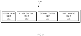
- the power supply management apparatus 210 may include a determining unit 211, a first control unit 212, a second control unit 213, and a third control unit 214.
- the determining unit 211 may perform a fault detection function that determines existence of a fault inside a system.
- the fault may be defined as a feature or a parameter of a component inside the system deviating from a prescribed condition by an allowable deviation or more.
- the determining unit 211 may determine a level of a fault when the fault occurs. For example, the determining unit 211 may determine whether the fault occurs in the battery management apparatus 200, and determine the level of the occurring fault.
- the level of the fault may be defined as a level determined according to an automotive safety integrity level (ASIL) risk level.
- ASIL level may be a criterion for determining a vehicle safety integrity level and may be determined according to severity, exposure, and controllability of damage caused by malfunction of vehicle parts through vehicle-level risk source analysis and risk assessment.
- the ASIL level may be classified into four categories ASIL A, ASIL B, ASIL C, and ASIL D.
- the ASIL level may define ASIL D as the highest risk criterion and ASIL A as the lowest risk criterion.
- the level of the fault of the BMS may be determined as the ASIL D level.
- the first control unit 212 may set a control point in time for cutting off power supply to a load according to a level of a fault and generate a first control command according to the control point in time.
- the first control unit 212 may set a control point in time for cutting off power supply to a load according to an ASIL level of the fault, received from the determining unit 211, and generate the first control command according to the control point in time.
- a case may occur where power supply has to be guaranteed up to a certain time, according to a level of the fault based on the ASIL level.
- a case where voltage measurement is impossible because a wiring harness terminal of the BMS is not fixed during driving of the vehicle, causing overcharging of a battery cell has a higher level of a risk caused by a fault than that of a case where the risk of battery ignition is caused and that of a case where a temporary communication error occurs in a network control device (an electronic control unit (ECU)) of the BMS, such that power supply may be maintained for a certain time without immediately cutting off the power supply.
- ECU electronice control unit
- the first control unit 212 may set a control point in time for cutting off power supply to a load according to a level of a fault to further supply power for a certain time without immediately cutting off the power supply.
- the first control unit 212 may generate the first control command by using a fault monitoring module and a controller.
- the fault monitoring module may monitor fault detection information including a level of a fault and set a control point in time for cutting off power supply to a load according to the level of the fault. That is, the first control unit 212 may set the control point in time for cutting off power supply according to an ASIL level of the fault, received from the determining unit 211, by using the fault monitoring module. The controller may generate the first control command according to the control point in time received from the fault monitoring module.
- the first control command may have a first value before the control point in time and have a second value from the control point in time.
- the first value may be a digital signal of 0, and the second value may be a digital signal of 1.
- the first control command may be a digital signal of 0 as a signal for not opening a power supply switch before the control point in time, and may be a digital signal of 1 as a signal for opening a power supply switch from the control point in time.
- the second control unit 213 may generate a second control command corresponding to a power supply maintaining time when a fault occurs. That is, when a fault occurs in an electric device, the second control unit 213 may set a minimum power supply maintaining time for maintaining power supply and generate a second control command that is a power supply command corresponding to the minimum power supply maintaining time.
- the second control unit 213 may generate the second control command by using a function inhibition manager (FIM) and a controller.
- FIM function inhibition manager
- the FIM may inhibit a function of a particular module under a specific condition.
- the FIM may set a power supply maintaining time for inhibiting opening of a switch (not shown) for power supply to the electric device.
- the controller may generate the second control command corresponding to the power supply maintaining time.
- the second control unit 213 may maintain the power supply by inhibiting opening of the switch for the power supply to the electric device during the power supply maintaining time through the FIM.
- the second control command may be a first value during the power supply maintaining time and be a second value after the power supply maintaining time.
- the first value may be a digital signal of 0, and the second value may be a digital signal of 1.
- the second control unit 213 may inhibit opening of the switch for the power supply for a specific time, separately from the first control command of the first control unit 212, by generating the second control command for controlling the power supply, thereby securing the minimum power supply maintaining time.
- the third control unit 214 may generate a third control command for controlling power supply to a load, based on the first control command and the second control command.
- the third control unit 214 may receive the first control command sent from the first control unit 212 and the second control command sent from the second control unit 213, thereby generating the third control command. That is, the third control unit 214 may be understood as a duplexing operation device based on the first control command and the second control command.
- the third control unit 214 may perform power supply management based on a duplexing operation, thereby guaranteeing power supply to the electric device even when a fault occurs in any one of the first control unit 212 and the second control unit 213.
- the third control unit 214 may prevent the switch for the power supply to the electric device from being opened earlier than the power supply maintaining time corresponding to the level of the fault or the minimum power supply maintaining time corresponding to occurrence of the fault, through such a duplexing operation.
- the third control unit 214 may generate the third control command for controlling the power supply to the load, by using one logic device that performs the duplexing operation.
- the third control unit 214 may include an OR logic gate or an AND logic gate.
- the third control unit 214 may generate the third control command for maintaining the power supply to the load when at least any one of the first control command and the second control command has the first value.
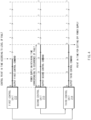
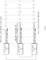
- FIGS. 4 and 5 show a process where the third control unit 214 of the power supply management apparatus 210 generates the third control command by using the AND logic gate.
- the digital signal of 0 may be a power supply signal, for example, a signal for prohibiting opening of a switch for power supply
- the digital signal of 1 may be a power supply cutoff signal, for example, a signal for opening the switch for the power supply.
- the third control unit 214 may output the third control command having the digital signal of 1 from a point in time when values of both the first control command and the second control command output the digital signal of 1, according to an operating principle of the AND logic gate.
- the power supply maintaining time of the second control unit 213 may expire after the control point in time of the first control unit 212.
- the AND logic gate of the third control unit 214 may receive the digital signal of 1 from both the first control unit 212 and the second control unit 213 and output the digital signal of 1 through an AND operation, after the power supply maintaining time of the second control unit 213. That is, the third control unit 214 may generate the third control command that is a power supply cutoff signal, after the power supply maintaining time of the second control unit 213.
- the control point in time of the first control unit 212 may arrive after the power supply maintaining time of the second control unit 213.
- the AND logic gate of the third control unit 214 may receive the digital signal of 1 from both the first control unit 212 and the second control unit 213 and output the digital signal of 1 through the AND operation, from the control point in time of the first control unit 212. That is, the third control unit 214 may generate the third control command that is a power supply cutoff signal, from the control point in time of the first control unit 212.
- the third control unit 214 when using the AND logic gate, may generate the third control command for maintaining the power supply to the load when at least any one of the first control command and the second control command has the digital signal of 0, which is the power supply signal, as the first value.
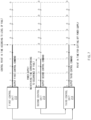
- FIGS. 6 and 7 show a process where the third control unit 214 of the power supply management apparatus 210 generates the third control command by using the OR logic gate.
- the digital signal of 1 may be a power supply signal, for example, a signal for prohibiting opening of a switch for power supply
- the digital signal of 0 may be a power supply cutoff signal, for example, a signal for opening the switch for the power supply.
- the third control unit 214 may output the digital signal of 0 as the third control command from a point in time when the values of both the first control command and the second control command output the digital signal of 0, according to an operating principle of the OR logic gate.
- the power supply maintaining time of the second control unit 213 may expire after the control point in time of the first control unit 212.
- the third control unit 214 may receive the digital signal of 0 from both the first control unit 212 and the second control unit 213 and output the digital signal of 0 through an OR operation, after the power supply maintaining time of the second control unit 213. That is, the third control unit 214 may generate the third control command that is the power supply cutoff signal, after the power supply maintaining time of the second control unit 213.
- the control point in time of the first control unit 212 may arrive after the power supply maintaining time of the second control unit 213.
- the third control unit 214 may receive the digital signal of 0 from both the first control unit 212 and the second control unit 213 and output the digital signal of 0 through the OR operation, from the control point in time of the first control unit 212. That is, the third control unit 214 may generate the third control command that is the power supply cutoff signal, from the control point in time of the first control unit 212.
- the third control unit 214 when using the OR logic gate, may generate the third control command for maintaining the power supply to the load when at least any one of the first control command and the second control command has the digital signal of 1, which is the power supply signal, as the first value.
- the third control unit 214 may generate the third control command for maintaining the power supply by using the AND logic gate or the OR logic gate, when at least any one of the first control command and the second control command outputs the power supply signal.
- the power supply management apparatus 210 even when generating a signal for cutting off power supply due to occurrence of an error in any one of the first control command and the second control command, may maintain the power supply to the electric signal based on a power supply signal of the other.
- the power supply management apparatus 210 may maintain power supply up to a certain point in time according to a level of a fault when the fault occurs in the electric device such as a BMS.
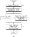
- FIG. 8 is a flowchart showing an operating method of a power supply management apparatus according to an embodiment disclosed herein.
- an operating method of a power supply management apparatus may include operation S101 of determining a level of a fault when the fault occurs, operation S 102 of setting a control point in time for cutting off power supply to a load according to the level of the fault, operation S103 of generating a first control command according to the control point in time, operation S 104 of generating a second control command corresponding to a power supply maintaining time when the fault occurs, and operation S105 of generating a third control command for controlling the power supply to the load based on the first control command and the second control command.
- the determining unit 211 may determine a level of a fault when the fault occurs.
- the level of the fault may be defined as a level determined according to an ASIL risk level.
- the determining unit 211 may set a control point in time for cutting off power supply to a load, according to the level of the fault.
- the first control unit 212 may generate a first control command according to the control point in time.
- the first control unit 212 may set the control point in time for cutting off the power supply to the load according to the level of the fault to further supply power for a certain time without immediately cutting off the power supply.
- the first control unit 212 may generate the first control command by using a fault monitoring module and a controller.
- the fault monitoring module may monitor fault detection information including the level of the fault and set the control point in time for cutting off the power supply to the load according to the level of the fault. That is, in operation S 103, the first control unit 212 may set the control point in time for cutting off power supply according to the ASIL level of the fault, received from the determining unit 211, by using the fault monitoring module. The controller may generate the first control command according to the control point in time received from the fault monitoring module.
- the first control command may have a first value before the control point in time and have a second value from the control point in time.
- the first value may be the digital signal of 0, and the second value may be the digital signal of 1.
- the first control command may have the first value before the control point in time and have the second value from the control point in time.
- the first value may be the digital signal of 0, and the second value may be the digital signal of 1.
- the second control unit 213 may generate a second control command corresponding to a power supply maintaining time when the fault occurs.
- the second control unit 213 may generate the second control command by using an FIM and a controller.
- the FIM may inhibit a function of a particular module under a specific condition. For example, when the fault is detected in the electric device, the FIM may set a power supply maintaining time for inhibiting opening of a switch (not shown) for power supply to the electric device.
- the controller may generate the second control command corresponding to the power supply maintaining time.
- the second control command may be the first value during the power supply maintaining time and be the second value after the power supply maintaining time.
- the first value may be the digital signal of 0, and the second value may be the digital signal of 1.
- the third control unit 214 may generate a third control command for controlling the power supply to the load, based on the first control command and the second control command.
- the third control unit 214 may generate the third control command by using the OR logic gate or the AND logic gate.
- the third control unit 214 may generate the third control command for controlling the power supply to the load, by using one logic device that performs the duplexing operation.
- the third control unit 214 may include the OR logic gate or the AND logic gate.
- the third control unit 214 may generate the third control command for maintaining the power supply to the load when at least any one of the first control command and the second control command has the first value.
Landscapes
- Engineering & Computer Science (AREA)
- Power Engineering (AREA)
- Life Sciences & Earth Sciences (AREA)
- Mechanical Engineering (AREA)
- Transportation (AREA)
- Sustainable Energy (AREA)
- Sustainable Development (AREA)
- Physics & Mathematics (AREA)
- General Physics & Mathematics (AREA)
- Microelectronics & Electronic Packaging (AREA)
- General Chemical & Material Sciences (AREA)
- Electrochemistry (AREA)
- Chemical Kinetics & Catalysis (AREA)
- Chemical & Material Sciences (AREA)
- Manufacturing & Machinery (AREA)
- Charge And Discharge Circuits For Batteries Or The Like (AREA)
- Direct Current Feeding And Distribution (AREA)
Abstract
Description
- This application claims priority to and the benefit of
Korean Patent Application No. 10-2021-0018651 filed in the Korean Intellectual Property Office on February 9, 2021 - Embodiments disclosed herein relate to a power supply management apparatus and an operating method thereof.
- When a fault occurs in a battery management system (BMS), it is sometimes necessary to guarantee power supply to an electric device up to a certain point in time depending on a level of the occurring fault. However, when an unexpected error occurs in a fault monitoring component or a control component of the BMS, a switch for maintaining or cutting off the power supply is opened earlier than an expected point in time, failing to guarantee the power supply to the electric device up to the certain point in time.
- As a result, when an error occurs in the fault monitoring component or the control component, the power supply to the electric device may be cut off early, causing an operation error in the electric device.
- Embodiments disclosed herein aim to provide a power supply management apparatus capable of maintaining power supply up to a certain point in time according to a level of a fault when the fault occurs in a BMS, and an operating method of the power supply management apparatus.
- Technical problems of the embodiments disclosed herein are not limited to the above-described technical problems, and other unmentioned technical problems would be clearly understood by one of ordinary skill in the art from the following description.
- A power supply management apparatus according to an embodiment disclosed herein includes a determining unit configured to determine a level of a fault when the fault occurs, a first control unit configured to set a control point in time for cutting off power supply to a load according to the level of the fault and generate a first control command according to the control point in time, a second control unit configured to generate a second control command corresponding to a power supply maintaining time when the fault occurs, and a third control unit configured to generate a third control command for controlling the power supply to the load, based on the first control command and the second control command.
- According to an embodiment, the first control command may have a first value before the control point in time and have a second value from the control point in time.
- According to an embodiment, the second control command may have the first value during the power supply maintaining time and have the second value after the power supply maintaining time.
- According to an embodiment, the third control unit may be further configured to generate the third control command for maintaining the power supply to the load when at least any one of the first control command and the second control command has the first value.
- According to an embodiment, the third control unit may include an OR logic gate or an AND logic gate.
- According to an embodiment, the second control unit may be further configured to generate the second control command by using a function inhibition manager (FIM).
- An operating method of a power supply management apparatus according to an embodiment disclosed herein includes determining a level of a fault when the fault occurs, setting a control point in time for cutting off power supply to a load according to the level of the fault, generating a first control command according to the control point in time, generating a second control command corresponding to a power supply maintaining time when the fault occurs, and generating a third control command for controlling the power supply to the load, based on the first control command and the second control command.
- According to an embodiment, the first control command may have a first value before the control point in time and have a second value from the control point in time.
- According to an embodiment, the second control command may have the first value during the power supply maintaining time and have the second value after the power supply maintaining time.
- According to an embodiment, the generating of the third control command for controlling the power supply to the load, based on the first control command and the second control command, comprises generating the third control command for maintaining the power supply to the load when at least any one of the first control command and the second control command has the first value.
- According to an embodiment, the generating of the third control command for controlling the power supply to the load, based on the first control command and the second control command, may include generating the third control command by using an OR logic gate or an AND logic gate.
- According to an embodiment, the generating of the second control command corresponding to the power supply maintaining time when the fault occurs may include generating the second control command by using a function inhibition manager (FIM).
- With a power supply management apparatus and an operating method thereof according to an embodiment disclosed herein, power supply may be maintained up to a certain point in time according to a level of a fault when the fault occurs in a BMS.
-
-
FIG. 1 illustrates a battery pack according to an embodiment disclosed herein. -
FIG. 2 is a block diagram of a power supply management apparatus according to an embodiment disclosed herein. -
FIG. 3 is a view for describing an operation of a power supply management apparatus, according to an embodiment disclosed herein. -
FIG. 4 shows a process in which a third control unit of a power supply management apparatus according to an embodiment disclosed herein generates a third control command by using an AND logic gate. -
FIG. 5 shows a process in which a third control unit of a power supply management apparatus according to another embodiment disclosed herein generates a third control command by using an AND logic gate. -
FIG. 6 shows a process in which a third control unit of a power supply management apparatus according to an embodiment disclosed herein generates a third control command by using an OR logic gate. -
FIG. 7 shows a process in which a third control unit of a power supply management apparatus according to another embodiment disclosed herein generates a third control command by using an OR logic gate. -
FIG. 8 is a flowchart showing an operating method of a power supply management apparatus according to an embodiment disclosed herein. - Hereinafter, some embodiments disclosed in this document will be described in detail with reference to the exemplary drawings. In adding reference numerals to components of each drawing, it should be noted that the same components are given the same reference numerals even though they are indicated in different drawings. In addition, in describing the embodiments disclosed in this document, when it is determined that a detailed description of a related known configuration or function interferes with the understanding of an embodiment disclosed in this document, the detailed description thereof will be omitted.
- To describe a component of an embodiment disclosed herein, terms such as first, second, A, B, (a), (b), etc., may be used. These terms are used merely for distinguishing one component from another component and do not limit the component to the essence, sequence, order, etc., of the component. The terms used herein, including technical and scientific terms, have the same meanings as terms that are generally understood by those skilled in the art, as long as the terms are not differently defined. Generally, the terms defined in a generally used dictionary should be interpreted as having the same meanings as the contextual meanings of the relevant technology and should not be interpreted as having ideal or exaggerated meanings unless they are clearly defined in the present document.
-
FIG. 1 illustrates a battery pack according to an embodiment disclosed herein. - Referring to
FIG. 1 , abattery pack 1000 according to an embodiment disclosed herein may include abattery module 100, abattery management apparatus 200, and arelay 300. - The
battery module 100 may include a plurality ofbattery cells FIG. 1 , the present invention is not limited thereto, and thebattery module 100 may include n battery cells (n is a natural number greater than or equal to 2). - The
battery module 100 may supply power to a target device (not shown). To this end, thebattery module 100 may be electrically connected to the target device. Herein, the target device may include an electrical, electronic, or mechanical device that operates by receiving power from thebattery pack 1000 including the plurality ofbattery cells - The plurality of
battery cells battery module 100 is illustrated inFIG. 1 , thebattery module 100 may be configured in plural according to an embodiment. - The
battery management apparatus 200 may manage and/or control a state and/or an operation of thebattery module 100. For example, thebattery management apparatus 200 may manage and/or control the states and/or operations of the plurality ofbattery cells battery module 100. Thebattery management apparatus 200 may manage charging and/or discharging of thebattery module 100. - In addition, the
battery management apparatus 200 may monitor a voltage, a current, a temperature, etc., of thebattery module 100 and/or each of the plurality ofbattery cells battery module 100. A sensor or various measurement modules for monitoring performed by thebattery management apparatus 200, which are not shown, may be additionally installed in thebattery module 100, a charging/discharging path, any position of thebattery module 100, etc. Thebattery management apparatus 200 may calculate a parameter indicating a state of thebattery module 100, e.g., a state of charge (SOC), a state of health (SOH) etc., based on a measurement value such as monitored voltage, current, temperature, etc. - The
battery management apparatus 200 may control an operation of therelay 300. For example, thebattery management apparatus 200 may short-circuit therelay 300 to supply power to the target device. Thebattery management apparatus 200 may short-circuit therelay 300 when a charging device is connected to thebattery pack 1000. - The
battery management apparatus 200 may calculate a cell balancing time of each of the plurality ofbattery cells battery management apparatus 200 may calculate a cell balancing time based on an SOC, a battery capacity, and a balancing efficiency of each of the plurality ofbattery cells - The
battery management apparatus 200 may include a powersupply management apparatus 210. - The power
supply management apparatus 210 may prevent a power supply switch (i.e., the relay 300) for maintaining or cutting off power supply to an electric device connected to thebattery pack 1000 from being opened earlier than a minimum power supply maintaining time, through a duplexing operation, thereby guaranteeing power supply to the electric device. - A battery management system (BMS), which is the
battery management apparatus 200, may detect a fault of thebattery pack 1000 and send fault detection information to another module, as a battery control system that identifies charging/discharging, a remaining battery capacity, etc. Thus, even when a mechanical or chemical defect occurs in thebattery management apparatus 200 or thebattery module 100, the ultimate safety of vehicle control may be provided by continuously supplying power to thebattery management apparatus 200. - Hereinbelow, a configuration and an operation of the power
supply management apparatus 210 will be described in detail. -
FIG. 2 is a block diagram of a battery supply management apparatus according to an embodiment disclosed herein.FIG. 3 shows an operating system of a power supply management apparatus, according to an embodiment disclosed herein. - Referring to
FIG. 2 , the powersupply management apparatus 210 according to an embodiment disclosed herein may include a determiningunit 211, afirst control unit 212, asecond control unit 213, and athird control unit 214. - The determining
unit 211 may perform a fault detection function that determines existence of a fault inside a system. Herein, the fault may be defined as a feature or a parameter of a component inside the system deviating from a prescribed condition by an allowable deviation or more. The determiningunit 211 may determine a level of a fault when the fault occurs. For example, the determiningunit 211 may determine whether the fault occurs in thebattery management apparatus 200, and determine the level of the occurring fault. - For example, the level of the fault may be defined as a level determined according to an automotive safety integrity level (ASIL) risk level. For example, the ASIL level may be a criterion for determining a vehicle safety integrity level and may be determined according to severity, exposure, and controllability of damage caused by malfunction of vehicle parts through vehicle-level risk source analysis and risk assessment.
- Herein, the ASIL level may be classified into four categories ASIL A, ASIL B, ASIL C, and ASIL D. The ASIL level may define ASIL D as the highest risk criterion and ASIL A as the lowest risk criterion.
- For example, when overvoltage or undervoltage occurs in a battery cell due to occurrence of a short-circuit in a battery module control cable of the BMS or a battery module diagnosis cable, such that a temperature of a battery rises and thus the risk of battery ignition is expected, then the level of the fault of the BMS may be determined as the ASIL D level.
- The
first control unit 212 may set a control point in time for cutting off power supply to a load according to a level of a fault and generate a first control command according to the control point in time. - That is, the
first control unit 212 may set a control point in time for cutting off power supply to a load according to an ASIL level of the fault, received from the determiningunit 211, and generate the first control command according to the control point in time. - For example, when a fault occurs in an electric device, a case may occur where power supply has to be guaranteed up to a certain time, according to a level of the fault based on the ASIL level.
- For example, a case where voltage measurement is impossible because a wiring harness terminal of the BMS is not fixed during driving of the vehicle, causing overcharging of a battery cell, has a higher level of a risk caused by a fault than that of a case where the risk of battery ignition is caused and that of a case where a temporary communication error occurs in a network control device (an electronic control unit (ECU)) of the BMS, such that power supply may be maintained for a certain time without immediately cutting off the power supply.
- Therefore, the
first control unit 212 may set a control point in time for cutting off power supply to a load according to a level of a fault to further supply power for a certain time without immediately cutting off the power supply. - For example, the
first control unit 212 may generate the first control command by using a fault monitoring module and a controller. - For example, the fault monitoring module may monitor fault detection information including a level of a fault and set a control point in time for cutting off power supply to a load according to the level of the fault. That is, the
first control unit 212 may set the control point in time for cutting off power supply according to an ASIL level of the fault, received from the determiningunit 211, by using the fault monitoring module. The controller may generate the first control command according to the control point in time received from the fault monitoring module. - Herein, the first control command may have a first value before the control point in time and have a second value from the control point in time. For example, the first value may be a digital signal of 0, and the second value may be a digital signal of 1.
- For example, the first control command may be a digital signal of 0 as a signal for not opening a power supply switch before the control point in time, and may be a digital signal of 1 as a signal for opening a power supply switch from the control point in time.
- The
second control unit 213 may generate a second control command corresponding to a power supply maintaining time when a fault occurs. That is, when a fault occurs in an electric device, thesecond control unit 213 may set a minimum power supply maintaining time for maintaining power supply and generate a second control command that is a power supply command corresponding to the minimum power supply maintaining time. - For example, the
second control unit 213 may generate the second control command by using a function inhibition manager (FIM) and a controller. Herein, the FIM may inhibit a function of a particular module under a specific condition. For example, when the fault is detected, the FIM may set a power supply maintaining time for inhibiting opening of a switch (not shown) for power supply to the electric device. The controller may generate the second control command corresponding to the power supply maintaining time. - That is, even when an unexpected operation error or a fault occurs in the fault monitoring module or the controller of the
first control unit 212, thesecond control unit 213 may maintain the power supply by inhibiting opening of the switch for the power supply to the electric device during the power supply maintaining time through the FIM. - For example, the second control command may be a first value during the power supply maintaining time and be a second value after the power supply maintaining time. For example, the first value may be a digital signal of 0, and the second value may be a digital signal of 1.
- Thus, the
second control unit 213 may inhibit opening of the switch for the power supply for a specific time, separately from the first control command of thefirst control unit 212, by generating the second control command for controlling the power supply, thereby securing the minimum power supply maintaining time. - The
third control unit 214 may generate a third control command for controlling power supply to a load, based on the first control command and the second control command. - Referring to
FIG. 3 , thethird control unit 214 may receive the first control command sent from thefirst control unit 212 and the second control command sent from thesecond control unit 213, thereby generating the third control command. That is, thethird control unit 214 may be understood as a duplexing operation device based on the first control command and the second control command. - The
third control unit 214 may perform power supply management based on a duplexing operation, thereby guaranteeing power supply to the electric device even when a fault occurs in any one of thefirst control unit 212 and thesecond control unit 213. - That is, the
third control unit 214 may prevent the switch for the power supply to the electric device from being opened earlier than the power supply maintaining time corresponding to the level of the fault or the minimum power supply maintaining time corresponding to occurrence of the fault, through such a duplexing operation. - The
third control unit 214 may generate the third control command for controlling the power supply to the load, by using one logic device that performs the duplexing operation. - For example, the
third control unit 214 may include an OR logic gate or an AND logic gate. Herein, thethird control unit 214 may generate the third control command for maintaining the power supply to the load when at least any one of the first control command and the second control command has the first value. -
FIGS. 4 and5 show a process where thethird control unit 214 of the powersupply management apparatus 210 generates the third control command by using the AND logic gate. Herein, the digital signal of 0 may be a power supply signal, for example, a signal for prohibiting opening of a switch for power supply, and the digital signal of 1 may be a power supply cutoff signal, for example, a signal for opening the switch for the power supply. - Referring to
FIGS. 4 and5 , thethird control unit 214 may output the third control command having the digital signal of 1 from a point in time when values of both the first control command and the second control command output the digital signal of 1, according to an operating principle of the AND logic gate. - More specifically, referring to
FIG. 4 , the power supply maintaining time of thesecond control unit 213 may expire after the control point in time of thefirst control unit 212. Thus, the AND logic gate of thethird control unit 214 may receive the digital signal of 1 from both thefirst control unit 212 and thesecond control unit 213 and output the digital signal of 1 through an AND operation, after the power supply maintaining time of thesecond control unit 213. That is, thethird control unit 214 may generate the third control command that is a power supply cutoff signal, after the power supply maintaining time of thesecond control unit 213. - Referring to
FIG. 5 , the control point in time of thefirst control unit 212 may arrive after the power supply maintaining time of thesecond control unit 213. Thus, the AND logic gate of thethird control unit 214 may receive the digital signal of 1 from both thefirst control unit 212 and thesecond control unit 213 and output the digital signal of 1 through the AND operation, from the control point in time of thefirst control unit 212. That is, thethird control unit 214 may generate the third control command that is a power supply cutoff signal, from the control point in time of thefirst control unit 212. - Thus, the
third control unit 214, when using the AND logic gate, may generate the third control command for maintaining the power supply to the load when at least any one of the first control command and the second control command has the digital signal of 0, which is the power supply signal, as the first value. -
FIGS. 6 and7 show a process where thethird control unit 214 of the powersupply management apparatus 210 generates the third control command by using the OR logic gate. Herein, the digital signal of 1 may be a power supply signal, for example, a signal for prohibiting opening of a switch for power supply, and the digital signal of 0 may be a power supply cutoff signal, for example, a signal for opening the switch for the power supply. - The
third control unit 214 may output the digital signal of 0 as the third control command from a point in time when the values of both the first control command and the second control command output the digital signal of 0, according to an operating principle of the OR logic gate. - First, referring to
FIG. 6 , the power supply maintaining time of thesecond control unit 213 may expire after the control point in time of thefirst control unit 212. Thus, thethird control unit 214 may receive the digital signal of 0 from both thefirst control unit 212 and thesecond control unit 213 and output the digital signal of 0 through an OR operation, after the power supply maintaining time of thesecond control unit 213. That is, thethird control unit 214 may generate the third control command that is the power supply cutoff signal, after the power supply maintaining time of thesecond control unit 213. - Referring to
FIG. 7 , the control point in time of thefirst control unit 212 may arrive after the power supply maintaining time of thesecond control unit 213. Thus, thethird control unit 214 may receive the digital signal of 0 from both thefirst control unit 212 and thesecond control unit 213 and output the digital signal of 0 through the OR operation, from the control point in time of thefirst control unit 212. That is, thethird control unit 214 may generate the third control command that is the power supply cutoff signal, from the control point in time of thefirst control unit 212. - Thus, the
third control unit 214, when using the OR logic gate, may generate the third control command for maintaining the power supply to the load when at least any one of the first control command and the second control command has the digital signal of 1, which is the power supply signal, as the first value. - As a result of referring to
FIGS. 3 through 6 , thethird control unit 214 may generate the third control command for maintaining the power supply by using the AND logic gate or the OR logic gate, when at least any one of the first control command and the second control command outputs the power supply signal. Thus, the powersupply management apparatus 210, even when generating a signal for cutting off power supply due to occurrence of an error in any one of the first control command and the second control command, may maintain the power supply to the electric signal based on a power supply signal of the other. - As described above, the power
supply management apparatus 210 according to an embodiment disclosed herein may maintain power supply up to a certain point in time according to a level of a fault when the fault occurs in the electric device such as a BMS. -
FIG. 8 is a flowchart showing an operating method of a power supply management apparatus according to an embodiment disclosed herein. - Referring to
FIG. 8 , an operating method of a power supply management apparatus according to an embodiment disclosed herein may include operation S101 of determining a level of a fault when the fault occurs, operation S 102 of setting a control point in time for cutting off power supply to a load according to the level of the fault, operation S103 of generating a first control command according to the control point in time, operation S 104 of generating a second control command corresponding to a power supply maintaining time when the fault occurs, and operation S105 of generating a third control command for controlling the power supply to the load based on the first control command and the second control command. - Hereinbelow, operations S 101 through S105 will be described in detail with reference to
FIG. 2 . - In operation S101, the determining
unit 211 may determine a level of a fault when the fault occurs. - For example, the level of the fault may be defined as a level determined according to an ASIL risk level.
- In operation S102, the determining
unit 211 may set a control point in time for cutting off power supply to a load, according to the level of the fault. - In operation S103, the
first control unit 212 may generate a first control command according to the control point in time. - In operation S 103, the
first control unit 212 may set the control point in time for cutting off the power supply to the load according to the level of the fault to further supply power for a certain time without immediately cutting off the power supply. - For example, in operation S103, the
first control unit 212 may generate the first control command by using a fault monitoring module and a controller. - For example, in operation S103, the fault monitoring module may monitor fault detection information including the level of the fault and set the control point in time for cutting off the power supply to the load according to the level of the fault. That is, in operation S 103, the
first control unit 212 may set the control point in time for cutting off power supply according to the ASIL level of the fault, received from the determiningunit 211, by using the fault monitoring module. The controller may generate the first control command according to the control point in time received from the fault monitoring module. - For example, in operation S103, the first control command may have a first value before the control point in time and have a second value from the control point in time. For example, the first value may be the digital signal of 0, and the second value may be the digital signal of 1.
- In operation S103, for example, the first control command may have the first value before the control point in time and have the second value from the control point in time. For example, the first value may be the digital signal of 0, and the second value may be the digital signal of 1.
- In operation S104, the
second control unit 213 may generate a second control command corresponding to a power supply maintaining time when the fault occurs. - In operation S104, for example, the
second control unit 213 may generate the second control command by using an FIM and a controller. Herein, the FIM may inhibit a function of a particular module under a specific condition. For example, when the fault is detected in the electric device, the FIM may set a power supply maintaining time for inhibiting opening of a switch (not shown) for power supply to the electric device. The controller may generate the second control command corresponding to the power supply maintaining time. - In operation S104, for example, the second control command may be the first value during the power supply maintaining time and be the second value after the power supply maintaining time. For example, the first value may be the digital signal of 0, and the second value may be the digital signal of 1.
- In operation S105, the
third control unit 214 may generate a third control command for controlling the power supply to the load, based on the first control command and the second control command. - In operation S105, the
third control unit 214 may generate the third control command by using the OR logic gate or the AND logic gate. - In operation S105, the
third control unit 214 may generate the third control command for controlling the power supply to the load, by using one logic device that performs the duplexing operation. - For example, in operation S105, the
third control unit 214 may include the OR logic gate or the AND logic gate. Herein, thethird control unit 214 may generate the third control command for maintaining the power supply to the load when at least any one of the first control command and the second control command has the first value. - The above description is merely illustrative of the technical idea of the present invention, and various modifications and variations will be possible without departing from the essential characteristics of the present invention by those of ordinary skill in the art to which the present invention pertains.
- Therefore, the embodiments disclosed in the present invention are intended for description rather than limitation of the technical spirit of the present invention and the scope of the technical spirit of the present invention is not limited by these embodiments. The protection scope of the present invention should be interpreted by the following claims, and all technical spirits within the same range should be understood to be included in the range of the present invention.
Claims (12)
- A power supply management apparatus comprising:a determining unit configured to determine a level of a fault when the fault occurs;a first control unit configured to set a control point in time for cutting off power supply to a load according to the level of the fault and generate a first control command according to the control point in time;a second control unit configured to generate a second control command corresponding to a power supply maintaining time when the fault occurs; anda third control unit configured to generate a third control command for controlling the power supply to the load, based on the first control command and the second control command.
- The power supply management apparatus of claim 1, wherein the first control command has a first value before the control point in time and has a second value from the control point in time.
- The power supply management apparatus of claim 2, wherein the second control command has the first value during the power supply maintaining time and has the second value after the power supply maintaining time.
- The power supply management apparatus of claim 3, wherein the third control unit may be further configured to generate the third control command for maintaining the power supply to the load when at least any one of the first control command and the second control command has the first value.
- The power supply management apparatus of claim 1, wherein the third control unit comprises an OR logic gate or an AND logic gate.
- The power supply management apparatus of claim 1, wherein the second control unit is further configured to generate the second control command by using a function inhibition manager (FIM).
- An operating method of a power supply management apparatus, the operating method comprising:determining a level of a fault when the fault occurs;setting a control point in time for cutting off power supply to a load according to the level of the fault;generating a first control command according to the control point in time;generating a second control command corresponding to a power supply maintaining time when the fault occurs; andgenerating a third control command for controlling the power supply to the load, based on the first control command and the second control command.
- The operating method of claim 7, wherein the first control command has a first value before the control point in time and has a second value from the control point in time.
- The operating method of claim 8, wherein the second control command has the first value during the power supply maintaining time and has the second value after the power supply maintaining time.
- The operating method of claim 9, wherein the generating of the third control command for controlling the power supply to the load, based on the first control command and the second control command, comprises generating the third control command for maintaining the power supply to the load when at least any one of the first control command and the second control command has the first value.
- The operating method of claim 7, wherein the generating of the third control command for controlling the power supply to the load, based on the first control command and the second control command, comprises generating the third control command by using an OR logic gate or an AND logic gate.
- The operating method of claim 7, wherein the generating of the second control command corresponding to the power supply maintaining time when the fault occurs comprises generating the second control command by using a function inhibition manager (FIM).
Applications Claiming Priority (2)
| Application Number | Priority Date | Filing Date | Title |
|---|---|---|---|
| KR1020210018651A KR20220114976A (en) | 2021-02-09 | 2021-02-09 | Apparatus and method for power supply management |
| PCT/KR2022/001835 WO2022173175A1 (en) | 2021-02-09 | 2022-02-07 | Power supply management device and operation method thereof |
Publications (2)
| Publication Number | Publication Date |
|---|---|
| EP4203235A1 true EP4203235A1 (en) | 2023-06-28 |
| EP4203235A4 EP4203235A4 (en) | 2024-05-22 |
Family
ID=82837683
Family Applications (1)
| Application Number | Title | Priority Date | Filing Date |
|---|---|---|---|
| EP22752935.1A Pending EP4203235A4 (en) | 2021-02-09 | 2022-02-07 | Power supply management device and operation method thereof |
Country Status (6)
| Country | Link |
|---|---|
| US (1) | US20230378785A1 (en) |
| EP (1) | EP4203235A4 (en) |
| JP (1) | JP7574993B2 (en) |
| KR (1) | KR20220114976A (en) |
| CN (1) | CN116324448A (en) |
| WO (1) | WO2022173175A1 (en) |
Family Cites Families (19)
| Publication number | Priority date | Publication date | Assignee | Title |
|---|---|---|---|---|
| JP2010110033A (en) * | 2008-10-28 | 2010-05-13 | Toyota Motor Corp | Device for determining abnormality in storage capacitor, and device for determining abnormality in vehicle and storage element |
| JP5910172B2 (en) * | 2012-03-01 | 2016-04-27 | 株式会社Gsユアサ | Switch failure diagnosis device, battery pack, switch failure diagnosis program, switch failure diagnosis method |
| JP2013240165A (en) * | 2012-05-14 | 2013-11-28 | Suzuki Motor Corp | Vehicle electric power supply device |
| DE102012209144A1 (en) * | 2012-05-31 | 2013-12-05 | Robert Bosch Gmbh | Method for transferring electrical drive system to safe state, involves switching off arrangement access to power supply over switching off path, where switching off path is formed such that path is tested in regular time spacings |
| JP5790598B2 (en) * | 2012-07-05 | 2015-10-07 | 株式会社デンソー | Battery control device |
| KR20150076843A (en) * | 2013-12-27 | 2015-07-07 | 현대자동차주식회사 | Protection circuit for battery of electric vehicle and driving method thereof |
| PL3043188T3 (en) * | 2014-02-17 | 2022-02-28 | Lg Chem, Ltd. | Battery management system |
| KR20170078414A (en) * | 2015-12-29 | 2017-07-07 | 삼성에스디아이 주식회사 | Battery pack |
| US10283982B2 (en) * | 2016-01-27 | 2019-05-07 | Gm Global Technology Operations Llc. | Voltage disconnect architecture |
| ES2913252T3 (en) * | 2016-05-13 | 2022-06-01 | Vito Nv | Method and apparatus of a modular management system for energy storage cells |
| KR102121639B1 (en) * | 2016-07-15 | 2020-06-10 | 주식회사 엘지화학 | System and method for perventing the abnormal opening of the contactor using real-time detection |
| US11451072B2 (en) * | 2018-07-10 | 2022-09-20 | Samsung Sdi Co., Ltd. | Battery system |
| EP3595076B1 (en) * | 2018-07-10 | 2020-05-13 | Samsung SDI Co., Ltd. | Battery system |
| CN109378884B (en) * | 2018-11-30 | 2021-04-27 | 湖南中联重科智能高空作业机械有限公司 | Fault grading and interaction control system and method based on battery management system |
| JP7095618B2 (en) * | 2019-02-19 | 2022-07-05 | トヨタ自動車株式会社 | Power supply |
| KR102686403B1 (en) * | 2019-03-06 | 2024-07-19 | 주식회사 엘지에너지솔루션 | Battery management system, method for checking the system |
| HUE063325T2 (en) * | 2019-07-25 | 2024-01-28 | Samsung Sdi Co Ltd | Battery system |
| EP3875300A1 (en) * | 2020-03-06 | 2021-09-08 | Volvo Car Corporation | Limp home mode for a battery electric vehicle |
| US11458845B2 (en) * | 2020-10-19 | 2022-10-04 | Vitesco Technologies USA, LLC | High voltage circuit and method for controlling a contactor in electric vehicles |
-
2021
- 2021-02-09 KR KR1020210018651A patent/KR20220114976A/en active Pending
-
2022
- 2022-02-07 JP JP2023518989A patent/JP7574993B2/en active Active
- 2022-02-07 US US18/030,419 patent/US20230378785A1/en active Pending
- 2022-02-07 WO PCT/KR2022/001835 patent/WO2022173175A1/en not_active Ceased
- 2022-02-07 CN CN202280006820.4A patent/CN116324448A/en active Pending
- 2022-02-07 EP EP22752935.1A patent/EP4203235A4/en active Pending
Also Published As
| Publication number | Publication date |
|---|---|
| WO2022173175A1 (en) | 2022-08-18 |
| US20230378785A1 (en) | 2023-11-23 |
| CN116324448A (en) | 2023-06-23 |
| KR20220114976A (en) | 2022-08-17 |
| JP2023544128A (en) | 2023-10-20 |
| EP4203235A4 (en) | 2024-05-22 |
| JP7574993B2 (en) | 2024-10-29 |
Similar Documents
| Publication | Publication Date | Title |
|---|---|---|
| US12117501B2 (en) | Battery management apparatus and method | |
| Weicker | A systems approach to lithium-ion battery management | |
| JP5791819B2 (en) | In-vehicle power storage device and control method thereof | |
| CN110783973A (en) | Li-ion battery high voltage power distribution system architecture | |
| JP7334734B2 (en) | Failure diagnosis method, storage device management device and system | |
| KR101745167B1 (en) | Method of detecting fault battery sell and system performing the same | |
| JP5978143B2 (en) | Battery system | |
| JPWO2018180520A1 (en) | Monitoring device and power storage system | |
| US9634500B2 (en) | Storage battery system | |
| EP4393777A1 (en) | Power supply system for vehicle | |
| US20240201268A1 (en) | Battery condition monitoring device and method, and battery protection device | |
| US12571847B2 (en) | Battery pack and method of controlling the same | |
| CN106688156B (en) | Vehicle battery system | |
| US11635471B2 (en) | Detecting latent faults within a cell of an energy storage system | |
| US20230378785A1 (en) | Power supply management apparatus and operating method thereof | |
| EP4425199B1 (en) | Battery data management apparatus and operating method thereof | |
| CN112034346B (en) | Method for fault detection in an electrical energy storage system | |
| US20250239661A1 (en) | Method for operating a battery pack for identifying an end-of-safe-operation | |
| KR20200124032A (en) | System and method for diagnosing battery current sensor | |
| EP4503368A1 (en) | Battery system monitoring device | |
| KR20170090137A (en) | Method for driving of Battery management system | |
| CN122070229A (en) | Battery control system | |
| JP2025070075A (en) | Anomaly detection method and anomaly detection device |
Legal Events
| Date | Code | Title | Description |
|---|---|---|---|
| STAA | Information on the status of an ep patent application or granted ep patent |
Free format text: STATUS: THE INTERNATIONAL PUBLICATION HAS BEEN MADE |
|
| PUAI | Public reference made under article 153(3) epc to a published international application that has entered the european phase |
Free format text: ORIGINAL CODE: 0009012 |
|
| STAA | Information on the status of an ep patent application or granted ep patent |
Free format text: STATUS: REQUEST FOR EXAMINATION WAS MADE |
|
| 17P | Request for examination filed |
Effective date: 20230322 |
|
| AK | Designated contracting states |
Kind code of ref document: A1 Designated state(s): AL AT BE BG CH CY CZ DE DK EE ES FI FR GB GR HR HU IE IS IT LI LT LU LV MC MK MT NL NO PL PT RO RS SE SI SK SM TR |
|
| DAV | Request for validation of the european patent (deleted) | ||
| DAX | Request for extension of the european patent (deleted) | ||
| A4 | Supplementary search report drawn up and despatched |
Effective date: 20240423 |
|
| RIC1 | Information provided on ipc code assigned before grant |
Ipc: G01R 31/36 20200101ALI20240417BHEP Ipc: H02J 7/00 20060101AFI20240417BHEP |
|
| STAA | Information on the status of an ep patent application or granted ep patent |
Free format text: STATUS: EXAMINATION IS IN PROGRESS |
|
| 17Q | First examination report despatched |
Effective date: 20250714 |