DE102012209144A1 - Method for transferring electrical drive system to safe state, involves switching off arrangement access to power supply over switching off path, where switching off path is formed such that path is tested in regular time spacings - Google Patents
Method for transferring electrical drive system to safe state, involves switching off arrangement access to power supply over switching off path, where switching off path is formed such that path is tested in regular time spacings Download PDFInfo
- Publication number
- DE102012209144A1 DE102012209144A1 DE201210209144 DE102012209144A DE102012209144A1 DE 102012209144 A1 DE102012209144 A1 DE 102012209144A1 DE 201210209144 DE201210209144 DE 201210209144 DE 102012209144 A DE102012209144 A DE 102012209144A DE 102012209144 A1 DE102012209144 A1 DE 102012209144A1
- Authority
- DE
- Germany
- Prior art keywords
- path
- switching
- arrangement
- power supply
- level
- Prior art date
- Legal status (The legal status is an assumption and is not a legal conclusion. Google has not performed a legal analysis and makes no representation as to the accuracy of the status listed.)
- Pending
Links
Images


Classifications
-
- G—PHYSICS
- G05—CONTROLLING; REGULATING
- G05B—CONTROL OR REGULATING SYSTEMS IN GENERAL; FUNCTIONAL ELEMENTS OF SUCH SYSTEMS; MONITORING OR TESTING ARRANGEMENTS FOR SUCH SYSTEMS OR ELEMENTS
- G05B9/00—Safety arrangements
- G05B9/02—Safety arrangements electric
-
- G—PHYSICS
- G01—MEASURING; TESTING
- G01R—MEASURING ELECTRIC VARIABLES; MEASURING MAGNETIC VARIABLES
- G01R31/00—Arrangements for testing electric properties; Arrangements for locating electric faults; Arrangements for electrical testing characterised by what is being tested not provided for elsewhere
Abstract
Description
Die Erfindung betrifft ein Verfahren zur Überführung eines elektrischen Antriebsystems in einen sicheren Zustand durch Abschaltung der Energieversorgung und eine Anordnung zur Durchführung des Verfahrens.The invention relates to a method for transferring an electric drive system to a safe state by switching off the power supply and an arrangement for carrying out the method.
Stand der TechnikState of the art
In Kraftfahrzeugen werden Steuergeräte zur Steuerung und Regelung der Komponenten eingesetzt. So ist u.a. ein Motorsteuergerät zur Steuerung und Regelung des Motors vorgesehen. Für den sicheren Betrieb des Kraftfahrzeugs ist es unerlässlich, die korrekte Funktionsweise des überwachten Steuergeräts kontinuierlich zu überprüfen und ggf. eine Energieversorgung abzuschalten.In motor vehicles, control devices are used to control and regulate the components. So is u.a. an engine control unit is provided for controlling and regulating the engine. For the safe operation of the motor vehicle, it is essential to continuously check the correct functioning of the monitored control unit and possibly switch off a power supply.
Bei Fahrzeugen mit einem sogenannten elektronischen Motorfüllungssteuerungssystem (EGAS) muss bspw. das 3-Ebenen-Konzept im Motorsteuergerät implementiert werden. Das 3-Ebenen-Konzept beruht auf der gegenseitigen Überwachung von Funktionsrechner und separatem Überwachungsmodul, dem sogenannten Watchdog. Der Funktionsrechner und das Überwachungsmodul kommunizieren über eine Frage/Antwort-Kommunikation und besitzen getrennte Abschaltpfade, über die die Leistungsendstufen bei Fehlerfällen abgeschaltet werden können und somit die Sicherheit des Fahrzeugs gewährleisten werden kann.In vehicles with a so-called electronic engine fill control system (EGAS), for example, the 3-level concept must be implemented in the engine control unit. The 3-level concept is based on the mutual monitoring of function computer and separate monitoring module, the so-called watchdog. The function computer and the monitoring module communicate via a question / answer communication and have separate shutdown paths, via which the power output stages can be switched off in case of faults and thus ensure the safety of the vehicle.
Die erste Ebene bzw. Ebene 1 bezeichnet die eigentliche Funktionssoftware, die zum Motorbetrieb notwendig ist. Diese wird auf dem Funktionsrechner ausgeführt. In der zweiten Ebene bzw. Ebene 2, die ebenfalls auf dem Funktionsrechner ausgeführt wird, wird anhand eines vereinfachten Motormodells ein zulässiges Moment mit einem Motor-Istmoment verglichen. Diese Ebene wird in einem durch die dritte Ebene bzw. Ebene 3 abgesicherten Hardwarebereich durchgeführt. Bestandteil der dritten Ebene ist der Befehlstest, die Programmablaufkontrolle, der A/D-Wandler-Test sowie zyklische und vollständige Speichertests.The first level or level 1 denotes the actual functional software, which is necessary for engine operation. This is executed on the function computer. In the second level or level 2, which is also executed on the function calculator, a permissible torque is compared with an actual engine torque based on a simplified engine model. This level is carried out in a hardware area protected by the third level or level 3. Part of the third level is the command test, the program flow control, the A / D converter test and cyclic and complete memory tests.
Bei aktuellen elektronischen Motorfüllungssteuerungssystemen befindet sich die gesamte Funktions- und Überwachungssoftware in einem Steuergerät. Aus der Druckschrift
Aus der Druckschrift
Die verteilte Überwachung auf mehreren Steuergeräten hat den Vorteil, dass die Ausfallwahrscheinlichkeit der Überwachungsfunktionalitäten durch zusätzliche Redundanz reduziert werden kann. Damit kann die verteilte Überwachung ein höheres Sicherheitsniveau bzw. eine höhere Automotive Safety Integrity Level (ASIL Level) als das 3-Ebenen Konzept erreichen.The distributed monitoring on several control devices has the advantage that the probability of failure of the monitoring functionalities can be reduced by additional redundancy. This means that distributed monitoring can achieve a higher level of safety or a higher level of Automotive Safety Integrity (ASIL) than the 3-level concept.
Bei Elektrofahrzeugen oder Hybrid-Fahrzeugen werden für das Elektroantriebsystem höhere ASIL Level als bei Verbrennungsmotoren gefordert, weil Elektromotoren in beide Richtungen ab Drehzahl Null ein maximales Drehmoment abgeben können. Ein Fehler in der Elektromotorsteuerung könnte bspw. ein ungewolltes maximales negatives Moment bewirken, was wiederum zu einer Blockade der Hinterachse und somit zum Schleudern des fahrenden Fahrzeugs führen könnte.With electric vehicles or hybrid vehicles, the electric drive system requires higher ASIL levels than internal combustion engines because electric motors can deliver maximum torque in both directions from zero speed. An error in the electric motor control could, for example, cause an undesired maximum negative torque, which in turn could lead to a blockage of the rear axle and thus to the skid of the moving vehicle.
Um höhere ASIL Level zu erreichen, wird das verteilte Überwachungskonzept eingesetzt. Dabei werden die Software-Module der zweiten Ebene auf zwei oder mehreren Steuergeräten dupliziert, so dass die Module der ersten Ebene in einem Steuergerät von den Modulen der zweiten Ebene aus beiden oder mehreren Steuergeräten überwacht werden. Die verteilten Module der zweiten Ebene kommunizieren mit der eigentlichen ersten Ebene und der zweiten Ebene über Kommunikationsnetzwerke, wie z.B. CAN, FlexRay oder Ethernet. To achieve higher ASIL levels, the distributed monitoring concept is used. In this case, the software modules of the second level are duplicated on two or more control units, so that the modules of the first level in a control unit are monitored by the modules of the second level of two or more control units. The distributed second-level modules communicate with the actual first level and the second level via communication networks, such as e.g. CAN, FlexRay or Ethernet.
Ein mögliches Abschaltkonzept bei der verteilten Überwachung ist die Abschaltung der Energieversorgung. Beide Steuergeräte können über eine Kommunikationsschnittstelle, bspw. CAN-Bus, FlexRay, Ethernet, SPI, Abschaltanforderungen an ein Energiemanagementsystem senden. Dies schaltet dann die Energieversorgung für das gesamte System ab.A possible shutdown concept for distributed monitoring is the shutdown of the power supply. Both control units can via a communication interface, for example. CAN bus, FlexRay, Ethernet, SPI, shutdown requests to a Send energy management system. This then shuts off the power supply to the entire system.
Ein solcher beschriebener Abschaltpfad muss mindestens ein Mal pro Fahrzyklus getestet werden, um seine ordnungsgemäße Arbeitsweise im Fehlerfall sicherzustellen. Ein möglicher Fehler im Abschaltpfad (Abschaltung Energieversorgung) ist ein schlafender Fehler, der in Kombination mit einem anderen Fehler zu einer Gefährdung führen kann. Ein schlafender Fehler muss detektiert werden können.Such a described shutdown path must be tested at least once per drive cycle to ensure its proper operation in the event of a fault. A possible fault in the shutdown path (shutdown of the power supply) is a sleeping fault that, in combination with another fault, can cause a hazard. A sleeping error must be detected.
Aus der Druckschrift
Die Druckschrift
Nachteilig bei bekannten Abschaltkonzepten ist, dass diese ein hohes ASIL Level in dem Energiemanagementsystem voraussetzen. Die Abschaltfunktionalität muss "eigensicher" sein. Häufig werden in einem Fahrzeug Komponenten von unterschiedlichen Zulieferern eingesetzt, so dass z.B. der Lieferant für das Antriebssystem nicht das Energiemanagementsystem liefert. Somit ist der Lieferant des Antriebssystems nicht allein für die Sicherheit seines Systems verantwortlich, sondern er ist auch abhängig von anderen Zulieferern.A disadvantage of known shutdown concepts is that they require a high ASIL level in the energy management system. The shutdown functionality must be "intrinsically safe". Frequently in a vehicle components from different suppliers are used, so that e.g. the supplier for the drive system does not supply the energy management system. Thus, the supplier of the drive system is not only responsible for the safety of his system, but he is also dependent on other suppliers.
Weiterhin ist zu beachten, dass das Hauptschütz, bspw. ein Unterbrecher-Relais, in dem Batteriesystem in der Regel nicht unter Last geöffnet werden sollte, da dies zu einer Beschädigung oder gar Zerstörung des Hauptschützes führen kann. Daher führt eine Abschaltung, um bspw. diese zu testen, zu einem erhöhten Wartungsaufwand und zusätzlichen Kosten. Außerdem wird durch diese Eigenschaft das Testen der Abschaltung während der Entwicklung erschwert.Furthermore, it should be noted that the main contactor, for example, a breaker relay, in the battery system should not be opened under load as a rule, as this may lead to damage or even destruction of the main contactor. Therefore, a shutdown, for example, to test these leads to increased maintenance and additional costs. In addition, this feature makes it difficult to test shutdown during development.
Offenbarung der ErfindungDisclosure of the invention
Vor diesem Hintergrund werden ein Verfahren nach Anspruch 1 und eine Anordnung mit den Merkmalen des Anspruchs 6 vorgestellt. Ausgestaltungen ergeben sich aus den abhängigen Ansprüchen und der Beschreibung.Against this background, a method according to claim 1 and an arrangement with the features of claim 6 are presented. Embodiments result from the dependent claims and the description.
Mit dem vorgestellten Verfahren wird erstmalig ein Abschaltpfadtest für die Abschaltung der Energieversorgung im Automotive-Bereich genutzt. Dabei erfolgt eine indirekte Abschaltung der leistungs- und momentenbestimmenden Endstufen aufgrund der abgeschalteten Energieversorgung. Auf diese Weise ist es möglich, die Fehlerreaktionszeit konstant und damit berechenbar und reproduzierbar zu halten. Bei dem Verfahren wird eine Energieversorgung abgeschaltet, um ein elektrisches Antriebssystem in einen sicheren Zustand zu überführen. Mittels Frage-Antwort-Kommunikation kann zudem sichergestellt werden, dass der Kommunikationsweg, bspw. eine Kommunikationsschnittstelle, zur Energieversorgung sowie die sendende und die empfangende Kommunikationseinheit noch funktionsfähig sind.For the first time, the shutdown path test for switching off the power supply in the automotive sector is used with the presented method. In this case, there is an indirect shutdown of the power and torque-determining output stages due to the disconnected power supply. In this way it is possible to keep the error reaction time constant and thus calculable and reproducible. In the method, a power supply is turned off to bring an electric drive system to a safe state. By means of question-answer communication it can also be ensured that the communication path, for example a communication interface, for the energy supply as well as the transmitting and the receiving communication unit are still functional.
Der Test des Abschaltpfads findet bspw. im sogenannten "Steuergeräte-Nachlauf" statt. Nachlauf bezeichnet die Phase, nachdem der Fahrer das Fahrzeug ausgeschaltet hat („Klemme 15“), aber das Steuergerät noch einige Dinge erledigt, wie bspw. die Ansteuerung der Lüfter, die Speicherung von Daten in EEPROM, bevor es sich komplett ausschaltet. Der Test findet bei dieser Ausführung nicht in der Steuergerätinitialisierung statt, da davon auszugehen ist, dass die Hauptschütze zur Energieversorgung zunächst geöffnet sind. Außerdem würde der Test die Initialisierungsdauer des Steuergeräts zu stark verlängern, so dass die Verfügbarkeit des Systems verschlechtert wird, der Fahrer also bspw. erst einige Sekunden warten muss, um das Fahrzeug zu starten und loszufahren.The test of Abschaltpfads takes place, for example, in the so-called "control unit overrun" instead. Caster refers to the phase after the driver has switched off the vehicle ("terminal 15"), but the controller still does some things, such as controlling the fans, storing data in EEPROM before it completely shuts off. The test does not take place in this version in the ECU initialization, since it can be assumed that the main contactors are initially open for power supply. In addition, the test would extend the initialization time of the controller too much, so that the availability of the system is deteriorated, so the driver, for example. Wait a few seconds to start the vehicle and go.
Wenn alle Bedingungen für den Start des Abschaltpfadtests erfüllt sind, bspw. dass kein Strom mehr über die (Batterie-)Hauptschütze fließt, was notwendig ist, da das Hauptschütz ansonsten irreversibel beschädigt wird, wird eine Abschaltung durch das Software-Testmodul, bspw. aus einem Steuergerät, angetriggert.If all the conditions for the start of the shutdown path test are met, for example, that no more current flows through the (battery) main contactors, which is necessary because otherwise the main contactor is irreversibly damaged, a shutdown by the software test module, for example a control unit, triggered.
Das Software-Testmodul hat nun mehrere Möglichkeiten die Abschaltung zu überprüfen.The software test module now has several options for checking the shutdown.
Eine einfache Methode besteht darin, die Rückmeldung aus dem Batterie Management Steuergerät (BMS) zu überprüfen. Falls das BMS zurückmeldet, dass die Hauptschütze erfolgreich aufgrund des Abschaltbefehls geöffnet worden sind, wird der Test erfolgreich beendet.A simple method is to check the feedback from the Battery Management Controller (BMS). If the BMS reports back that the main contactors have been successfully opened due to the shutdown command, the test is successfully completed.
Eine aufwendigere aber sicherere Methode kann durchgeführt werden, indem zusätzlich der Abfall der Hochvolt-Spannungsversorgung in dem eigenen Steuergerät überprüft wird. Dabei wird nach dem Senden des Abschaltbefehls eine geeignet definierte Zeit abgewartet. Anschließend wird leistungsstufenseitig die noch zur Verfügung stehende Spannung gemessen. Ist die Spannung kleiner als eine bestimmte Schwelle, unter der die Endstufen des Steuergeräts nicht mehr aktiviert werden können und somit das Fahrzeug nicht mehr bewegt werden kann, dann wird der Test erfolgreich abgeschlossen. A more complex but safer method can be performed by additionally checking the drop in the high-voltage power supply in your own control unit. In this case, a suitably defined time is waited after sending the shutdown command. Subsequently, the still available voltage is measured on the power stage side. If the voltage is less than a certain threshold, under which the power amplifiers of the control unit can not be activated and thus the vehicle can not be moved, then the test is completed successfully.
Falls der Test fehlerhaft beendet ist, wird keine sofortige Reaktion ausgelöst, da das Fahrzeug bereits ausgeschaltet ist. Das Testmodul speichert stattdessen den Fehler im nicht flüchtigen Speicher des Steuergeräts bzw. der Steuergeräte ab. Zu Beginn des nächsten Fahrzyklus wird dann dieser Fehler ausgewertet und ggf. ein Fehlerzähler inkrementiert. Ist der Fehlerzähler größer als eine applizierbare Schwelle, wird ein irreversibler Fehler gesetzt, der den (Gesamt-)Systemstart verhindert, so dass die Moment stellenden Endstufen abgeschaltet sind und das Fahrzeug nicht mehr bewegt werden kann. Erst nach einem erneuten Test der Abschaltung, welcher erfolgreich abgeschlossen werden muss, kann dieser Zustand wieder verlassen werden.If the test is terminated incorrectly, no immediate reaction is triggered because the vehicle is already switched off. Instead, the test module stores the error in the non-volatile memory of the control unit or the control units. At the beginning of the next drive cycle, this error is then evaluated and, if necessary, an error counter is incremented. If the error counter is greater than an applicable threshold, an irreversible error is set, which prevents the (overall) system start, so that the momentary end stages are switched off and the vehicle can no longer be moved. Only after a new test of the shutdown, which must be completed successfully, this state can be left again.
Um die eigentliche Kommunikationsschnittstelle zu überprüfen, erfolgt eine zyklische Frage-Antwort-Kommunikation. Sollte nach einer erfolgten Frage die erwartete Antwort nicht korrekt, d.h. bspw. nicht in einem erwarteten Zeitfenster oder mit falschem Antwortbeitrag, zurückübermittelt werden, so soll ebenfalls das Abschalten der Hochvolt-Spannungsversorgung erfolgen. Zur Bildung der Frage bzw. zur Kontrolle der korrekten Antwort kann das aus dem 3-Ebenen-Konzept bekannte Überwachungsmodul des Energiemanagement-Systems, erweitert um den zusätzlichen Kommunikationsschnittstellentest-Teil, genutzt werden.In order to check the actual communication interface, a cyclic question-answer communication takes place. If, after a successful question, the expected answer is not correct, i. For example, not in an expected time window or with an incorrect response, to be returned, so also the shutdown of the high voltage power supply. To form the question or to check the correct answer, the monitoring module of the energy management system known from the 3-level concept can be used, supplemented by the additional communication interface test part.
Weitere Vorteile und Ausgestaltungen der Erfindung ergeben sich aus der Beschreibung und den beiliegenden Zeichnungen.Further advantages and embodiments of the invention will become apparent from the description and the accompanying drawings.
Es versteht sich, dass die voranstehend genannten und die nachstehend noch zu erläuternden Merkmale nicht nur in der jeweils angegebenen Kombination, sondern auch in anderen Kombinationen oder in Alleinstellung verwendbar sind, ohne den Rahmen der vorliegenden Erfindung zu verlassen.It is understood that the features mentioned above and those yet to be explained below can be used not only in the particular combination indicated, but also in other combinations or in isolation, without departing from the scope of the present invention.
Kurze Beschreibung der ZeichnungenBrief description of the drawings
Ausführungsformen der ErfindungEmbodiments of the invention
Die Erfindung ist anhand von Ausführungsformen in den Zeichnungen schematisch dargestellt und wird nachfolgend unter Bezugnahme auf die Zeichnungen ausführlich beschrieben.The invention is schematically illustrated by means of embodiments in the drawings and will be described in detail below with reference to the drawings.
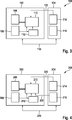
In einer ersten Ebene
Somit werden Ebene-1-Module von den Ebene-2-Modulen aus den beiden Steuergeräten
In
In den beteiligten Steuergeräten
Zwischen dem Mikrocontroller
In
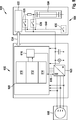
In
Bei der in
Eine Kombination dieser Variante mit der Variante aus
In dem Energiesystem
ZITATE ENTHALTEN IN DER BESCHREIBUNG QUOTES INCLUDE IN THE DESCRIPTION
Diese Liste der vom Anmelder aufgeführten Dokumente wurde automatisiert erzeugt und ist ausschließlich zur besseren Information des Lesers aufgenommen. Die Liste ist nicht Bestandteil der deutschen Patent- bzw. Gebrauchsmusteranmeldung. Das DPMA übernimmt keinerlei Haftung für etwaige Fehler oder Auslassungen.This list of the documents listed by the applicant has been generated automatically and is included solely for the better information of the reader. The list is not part of the German patent or utility model application. The DPMA assumes no liability for any errors or omissions.
Zitierte PatentliteraturCited patent literature
- DE 4438714 A1 [0005] DE 4438714 A1 [0005]
- DE 10331872 A1 [0006] DE 10331872 A1 [0006]
- DE 10152273 B4 [0012] DE 10152273 B4 [0012]
- DE 102006018053 A1 [0013] DE 102006018053 A1 [0013]
Claims (10)
Priority Applications (1)
| Application Number | Priority Date | Filing Date | Title |
|---|---|---|---|
| DE201210209144 DE102012209144A1 (en) | 2012-05-31 | 2012-05-31 | Method for transferring electrical drive system to safe state, involves switching off arrangement access to power supply over switching off path, where switching off path is formed such that path is tested in regular time spacings |
Applications Claiming Priority (1)
| Application Number | Priority Date | Filing Date | Title |
|---|---|---|---|
| DE201210209144 DE102012209144A1 (en) | 2012-05-31 | 2012-05-31 | Method for transferring electrical drive system to safe state, involves switching off arrangement access to power supply over switching off path, where switching off path is formed such that path is tested in regular time spacings |
Publications (1)
| Publication Number | Publication Date |
|---|---|
| DE102012209144A1 true DE102012209144A1 (en) | 2013-12-05 |
Family
ID=49579402
Family Applications (1)
| Application Number | Title | Priority Date | Filing Date |
|---|---|---|---|
| DE201210209144 Pending DE102012209144A1 (en) | 2012-05-31 | 2012-05-31 | Method for transferring electrical drive system to safe state, involves switching off arrangement access to power supply over switching off path, where switching off path is formed such that path is tested in regular time spacings |
Country Status (1)
| Country | Link |
|---|---|
| DE (1) | DE102012209144A1 (en) |
Cited By (3)
| Publication number | Priority date | Publication date | Assignee | Title |
|---|---|---|---|---|
| WO2019223995A1 (en) | 2018-05-22 | 2019-11-28 | Volkswagen Aktiengesellschaft | Electrical on-board network device for supplying at least two electrical consumers in a motor vehicle, and motor vehicle, switchover device, and method for operating an electrical on-board network device |
| CN111133389A (en) * | 2017-09-18 | 2020-05-08 | 罗伯特·博世工具公司 | Method for ensuring safety-critical functions of an electric machine |
| US11493896B2 (en) | 2018-04-25 | 2022-11-08 | Robert Bosch Gmbh | Turn-off device for components in safety-critical systems |
Citations (4)
| Publication number | Priority date | Publication date | Assignee | Title |
|---|---|---|---|---|
| DE4438714A1 (en) | 1994-10-29 | 1996-05-02 | Bosch Gmbh Robert | Method and device for controlling the drive unit of a vehicle |
| DE10331872A1 (en) | 2003-07-14 | 2005-02-10 | Robert Bosch Gmbh | Method for monitoring a technical system |
| DE10152273B4 (en) | 2001-10-20 | 2007-03-08 | Robert Bosch Gmbh | Method and device for monitoring a redundant shutdown path |
| DE102006018053A1 (en) | 2006-04-19 | 2007-10-31 | Daimlerchrysler Ag | Drive system for an electric machine |
-
2012
- 2012-05-31 DE DE201210209144 patent/DE102012209144A1/en active Pending
Patent Citations (4)
| Publication number | Priority date | Publication date | Assignee | Title |
|---|---|---|---|---|
| DE4438714A1 (en) | 1994-10-29 | 1996-05-02 | Bosch Gmbh Robert | Method and device for controlling the drive unit of a vehicle |
| DE10152273B4 (en) | 2001-10-20 | 2007-03-08 | Robert Bosch Gmbh | Method and device for monitoring a redundant shutdown path |
| DE10331872A1 (en) | 2003-07-14 | 2005-02-10 | Robert Bosch Gmbh | Method for monitoring a technical system |
| DE102006018053A1 (en) | 2006-04-19 | 2007-10-31 | Daimlerchrysler Ag | Drive system for an electric machine |
Cited By (4)
| Publication number | Priority date | Publication date | Assignee | Title |
|---|---|---|---|---|
| CN111133389A (en) * | 2017-09-18 | 2020-05-08 | 罗伯特·博世工具公司 | Method for ensuring safety-critical functions of an electric machine |
| US11493896B2 (en) | 2018-04-25 | 2022-11-08 | Robert Bosch Gmbh | Turn-off device for components in safety-critical systems |
| WO2019223995A1 (en) | 2018-05-22 | 2019-11-28 | Volkswagen Aktiengesellschaft | Electrical on-board network device for supplying at least two electrical consumers in a motor vehicle, and motor vehicle, switchover device, and method for operating an electrical on-board network device |
| US11345240B2 (en) | 2018-05-22 | 2022-05-31 | Volkswagen Aktiengesellschaft | Electrical on-board network device for supply of at least two electrical loads in a motor vehicle, and motor vehicle, switching device, and method for operating an on-board network device |
Similar Documents
| Publication | Publication Date | Title |
|---|---|---|
| DE102008022776B4 (en) | Simplified automatic unloading function for vehicles | |
| DE102018201119A1 (en) | Method for monitoring the power supply of a motor vehicle with automated driving function | |
| DE102013225020A1 (en) | On-board network for fault-tolerant and redundant supply | |
| DE102011008795A1 (en) | Method and apparatus for monitoring electrical ground isolation in a powertrain system | |
| DE102011055258A1 (en) | Control device for a motor vehicle | |
| DE112017004002B4 (en) | abnormality diagnosis device | |
| DE102018103196A1 (en) | CONTROLLING A REDUNDANT PERFORMANCE ARCHITECTURE FOR A VEHICLE | |
| DE102008000904A1 (en) | Method and device for controlling an electric machine of a hybrid drive with increased availability | |
| DE102019118804A1 (en) | Anomalitätsbestimmungssystem | |
| EP2720900B1 (en) | Method for the safe deactivation of a high voltage network of a motor vehicle | |
| DE102020210046A1 (en) | Method for operating a battery system | |
| DE102008009652A1 (en) | Monitoring device and monitoring method for a sensor, and sensor | |
| DE102011118172A1 (en) | Method for controlling electromotor in electric vehicle, involves determining target motor position angle of electric motor in emergency operation, in case of failure of position sensor by simulation unit | |
| DE102016221250A1 (en) | Method for operating a vehicle electrical system | |
| DE102012209144A1 (en) | Method for transferring electrical drive system to safe state, involves switching off arrangement access to power supply over switching off path, where switching off path is formed such that path is tested in regular time spacings | |
| DE102015200121A1 (en) | Method for monitoring a vehicle electrical system | |
| DE102012104322B4 (en) | Method for testing two processing units in battery management system of motor car, involves communicating a comparison result to battery control unit for carrying out decision-making process on continued operation of motor car device | |
| WO2017153318A1 (en) | Method and apparatus for supplying electric power to a device | |
| DE102009055044A1 (en) | Method and device for suppressing an unwanted acceleration of a vehicle | |
| DE102010017863A1 (en) | Method for detecting error in hybrid power train of electrically propelled vehicle, involves stopping energy supply to electromotor of vehicle when fault drive torque is identified at electromotor | |
| DE102015213831A1 (en) | Method for decommissioning an electrically controlled component of a vehicle in the event of a fault of a component unit controlling the component | |
| DE102010002468A1 (en) | Method for stopping functional unit operated by controller in motor vehicle, involves operating functional unit by internal output circuit of controller | |
| DE102020215648A1 (en) | Method for controlling a power supply system for a mild hybrid electric vehicle | |
| DE102013208700A1 (en) | Motor vehicle with at least two propulsion factors and increased reliability, operating methods and means for its implementation | |
| DE102017216460A1 (en) | Vehicle with electric drive device, in particular for autonomous driving, and method for driving drive and steering devices in such a vehicle |
Legal Events
| Date | Code | Title | Description |
|---|---|---|---|
| R012 | Request for examination validly filed |